
DualisHeat - Heating Klarstein - Free user manual and instructions
Find the device manual for free DualisHeat Klarstein in PDF.

| Brand | Klarstein |
| Model | DualisHeat |
| Product type | Infrared heating |
| Article number | 10047607 |
| Power supply | 220-240 V ~ / 50 Hz |
| Power | 2000 W |
| Power levels | 8 (1 to 8) |
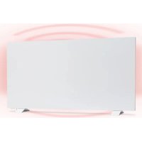
| Mounting type | Wall-mounted or freestanding |
| Control | Rotary knob and remote control |
| Timer | 1 to 8 hours |
| Use | Indoor and outdoor |
| Safety distance | 1 m from flammable materials, 1.8 m from floor, 0.5 m from ceiling |
| Maintenance | Regular cleaning of reflector and filament |
| Cleaning | With a soft cloth, no chemicals |
| Reflector replacement | Recommended every 2 years |
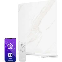
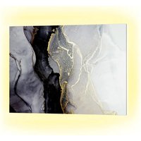
| Included accessories | Mounting brackets, screws, wall plugs, remote control, decorative covers |
| Manufacturer | Chal-Tec GmbH, Mühlenstraße 25, 10243 Berlin, Germany |
Frequently Asked Questions - DualisHeat Klarstein
User questions about DualisHeat Klarstein
0 question about this device. Answer the ones you know or ask your own.
Ask a new question about this device
Download the instructions for your Heating in PDF format for free! Find your manual DualisHeat - Klarstein and take your electronic device back in hand. On this page are published all the documents necessary for the use of your device. DualisHeat by Klarstein.
USER MANUAL DualisHeat Klarstein
bar
| Category | Value | |---|---| | Category 1 | 100 | | Category 2 | 100 | | Category 3 | 100 | | Category 4 | 100 | | Category 5 | 100 | | Category 6 | 100 | | Category 7 | 100 | | Category 8 | 100 | | Category 9 | 100 | | Category 10 | 100 | | Category 11 | 100 | | Category 12 | 100 | | Category 13 | 100 | | Category 14 | 100 | | Category 15 | 100 | | Category 16 | 100 | | Category 17 | 100 | | Category 18 | 100 | | Category 19 | 100 | | Category 20 | 100 | | Category 21 | 100 | | Category 22 | 100 | | Category 23 | 100 | | Category 24 | 100 | | Category 25 | 100 | | Category 26 | 100 | | Category 27 | 100 | | Category 28 | 100 | | Category 29 | 100 | | Category 30 | 100 | | Category 31 | 100 | | Category 32 | 100 | | Category 33 | 100 | | Category 34 | 100 | | Category 35 | 100 | | Category 36 | 100 | | Category 37 | 100 | | Category 38 | 100 | | Category 39 | 100 | | Category 40 | 100 | | Category 41 | 100 | | Category 42 | 100 | | Category 43 | 100 | | Category 44 | 100 | | Category 45 | 100 | | Category 46 | 100 | | Category 47 | 100 | | Category 48 | 100 | | Category 49 | 100 | | Category 50 | 100 | | Category 51 | 100 | | Category 52 | 100 | | Category 53 | 100 | | Category 54 | 100 | | Category 55 | 100 | | Category 56 | 100 | | Category 57 | 100 | | Category 58 | 100 | | Category 59 | 100 | | Category 60 | 100 | | Category 61 | 100 | | Category 62 | 100 | | Category 63 | 100 | | Category 64 | 100 | | Category 65 | 100 | | Category 66 | 100 | | Category 67 | 100 | | Category 68 | 100 | | Category 69 | 100 | | Category 70 | 100 | | Category 71 | 100 | | Category 72 | 100 | | Category 73 | 100 | | Category 74 | 100 | | Category 75 | 100 | | Category 76 | 100 | | Category 77 | 100 | | Category 78 | 100 | | Category 79 | 100 | | Category 80 | 100 | | Category 81 | 100 | | Category 82 | 100 | | Category 83 | 100 | | Category 84 | 100 | | Category 85 | 100 | | Category 86 | 100 | | Category 87 | 100 | | Category 88 | 100 | | Category 89 | 100 | | Category 90 | 100 | | Category 91 | 100 | | Category 92 | 100 | | Category 93 | 100 | | Category 94 | 100 | | Category 95 | 100 | | Category 96 | 100 | | Category 97 | 100 | | Category 98 | 100 | | Category 99 | 100 | | Total (Total) = [sum of bars] / [values] * (sum of bars + bars) * (sum of bars + bars) * (sum of bars + bars) * (sum of bars + bars) * (sum of bars + bars) * (sum of bars + bars) * (sum of bars + bars) * (sum of bars + bars) * (sum of bars + bars) * (sum of bars + bars) * (sum of bars + bars) * (sum of bars + bars) * (sum of bars + bars) * (sum in brackets) * (sum in brackets) * (sum in brackets) * (sum in brackets) * (sum in brackets) * (sum in brackets) * (sum in brackets) * (sum in brackets) * (sum in brackets) * (sum in brackets) * (sum in brackets) * (sum in brackets) * (sum in brackets) * (sum in brackets) * (sum in brackets) * (sum in brackets) * (sum in brackets) * (total).* (sum in brackets) * (sum in brackets) * (sum in brackets) * (sum in brackets) * (sum in brackets) * (sum in brackets) * (sum in brackets) * (sum in brackets) * (sum in brackets) * (sum in brackets) * (sum in brackets) * (sum in brackets) * (total).* (sum in brackets) * (sum in brackets) * (sum in brackets) * (sum in brackets)INHALT
Technische Daten 3
natural_image
Technical line drawing of a mechanical component with two downward arrows indicating force or movement (no text or symbols present)natural_image
Mechanical assembly diagram showing two components with bolts and a directional arrow (no text or labels)natural_image
Technical line drawing of a mechanical component with two blue arrows pointing to features (no text or symbols)natural_image
Technical line drawing of a mechanical component with two blue arrows pointing to features (no text or symbols)natural_image
Pure diagram of a mechanical or structural component with two vertical supports and a central circular feature, no text or symbols present.BEDIENUNGSANLEITUNG
natural_image
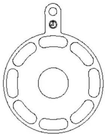
Technical line drawing of a circular mechanical component with six symmetrical slots and a central hole (no text or symbols)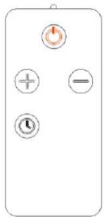
natural_image
Pure electrical control panel diagram without any text, numbers, or symbolsnatural_image
Symbol of a trash bin with crossed lines indicating no waste, and a solid black rectangle below (no text or labels)Congratulations on purchasing this equipment. Please read this manual carefully and take care of the following hints to avoid damages. Any failure caused by ignoring the items and cautions mentioned in the instruction manual are not covered by our warranty and any liability. Scan the QR code to get access to the latest user manual and other information about the product.

CONTENTS
Technical Specifications 15
Safety Instructions 16
Installation# 18
Operation INstruction 21
Maintenance and Cleaning 22
Disposal Considerations 23
Manufacturer & Importer (UK) 23
TECHNICAL SPECIFICATIONS
| Article number 10047607 | |
| Power supply 220-240 V~ / 50 Hz | |
| Power 2000 W | |
| Power levels 8 | |
| Mounting wall-mounted or free-standing | |
SAFETY INSTRUCTIONS
Please read all instructions before trying to operate this device. Keep the assembly instructions for future reference. Keep the assembly instructions for future reference. When storing the heater during a long period of non-use, please keep the original packaging for use.
- Do not leave this device unattended when using it.
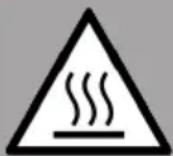
- This heater will get hot when in use. Do not touch hot surfaces.
- Do not move the device when using it. Before moving, please wait for the heater to cool completely, and check whether the heater has been unplugged from the power supply.
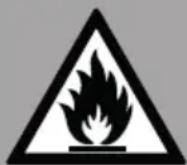
- Place the device at least 1m away from highly flammable materials such as furniture, trees, leaves, hay and bushes.
- The heater must be at least 1.8m (6ft) above the ground and at least 0.7m (2.5ft) above the building ceiling or hanging objects.
- The heater must not face up, towards the ceiling. The heater element must face the area to be heated.
- Keep children and pets at a safe distance away from equipment.
- Children aged 8 and above, as well as people with reduced physical, sensory or mental abilities or lack of experience and knowledge, can use this equipment, provided that they have received supervision or guidance on safe use of this equipment and know the dangers involved.
• Children are not allowed to play with the equipment. Without supervision, children are not allowed to carry out cleaning and user maintenance. - If there are any signs of damage or malfunction, do not operate the heater.
- Do not try to repair or adjust any electrical or mechanical functions on this device. The device does not contain any user-serviceable parts. Only qualified electricians can carry out maintenance or repair. Trying to repair the equipment yourself will void your warranty.
- If the power cable is damaged, it must be replaced by the manufacturer, its service agent or similar qualified personnel to avoid danger.
- Do not operate components with bare hands. If accidentally touched, use a soft cloth and methylated alcohol or alcohol to remove finger marks, otherwise these marks will burn into the components, resulting in premature failure of the heater.
- Do not replace or attempt to replace the components in this product.
- This product is suitable for outdoor use only. Do not use this heater near the bathroom, shower or swimming pool.
- Do not touch the plug with wet hands or wet hands.
- Do not run the power cord under the carpet. Do not cover the power cord with carpet, slide or similar covering. Place the power cord away from pedestrians and where you won't trip.
- Do not wrap the power cord around the equipment.
-
Do not insert or allow foreign objects into any ventilation or opening of the heater, as this may cause electric shock, fire or damage to the heater.
• To prevent possible fire, do not block the vent. -
There are heating and arc or spark parts inside the heater. Do not use it in areas where gasoline, paint, explosives and/or flammable liquids are used or stored. Keep the equipment away from heated surfaces and open flames.
- Avoid using extension cords as much as possible, as this may overheat and cause a fire. However, if you have to use the extension cable, please make sure that it is suitable for the purpose, has been tested for outdoor use, and it is best to have RCD equipment installed or connected.
- Always make sure that the heater is plugged into a suitable socket, which has been tested for outdoor use.
- To disconnect the heater, turn off the controller and unplug it from the socket. Do not unplug the plug by pulling the power cord.
- Before moving, cleaning or storing, always unplug the equipment to ensure that it is completely cooled.
- This heater is for domestic use only and should not be used for commercial contract purposes. Any alternative use not recommended by the manufacturer may cause fire, electric shock or personal injury.
- It is not recommended to use accessories on the heater.
- Before installing the heater, check the outer wall for damaged areas.
• Always use on dry, properly firm, stable, flat and horizontal surfaces. - Check the communication, cable and pipeline of the external wall. If there are any service lines nearby, please don't install the heater and find another place to install this product.
- Do not put it directly above or below the power outlet.
- Do not remove any warning labels or signs from the product.

CAUTION
Fire hazard
Never cover the heater. If you cover the device, there is a risk of overheating and fire. The heater must not be placed directly under a power socket.
CAUTION
Risk of burns
Some parts of this appliance can become very hot and cause burns. Special care should be taken when children and infirm persons are present.
CAUTION
Risk of personal injury
his heater is not equipped with a device to control the room temperature. Unless there is continuous supervision, don't use this heater in a small room occupied by people who can't leave the room by themselves..
INSTALLATION#
Included in the package:
| Part Qty Part Qty | |||
| M6*25 screws 2 Gaskets 4 | |||
| Decorative cover 1 M6 butterfly tail nuts 2 | |||
| Hanging brackets 4 Plastic expansion 4 | |||
| M6*16 butterfly tail screws 6 | ST4*35 | self-tapping screws 4 | |
Wall-mounted installation
These precautions need to be taken before installation
• The product should be put down gently;
- Do not install in acid and alkali environment;
• The product must be grounded.
- Check whether the nameplate mark on the product voltage conforms to the local voltage.
- Ensure that the cable socket has sufficient current carrying capacity.
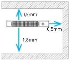
The installation position of the product should be placed 1.8 m from the ground, with a minimum distance of 0.5 m from the bottom of the ceiling, roof or other covering and a minimum distance of 0.5 m from the walls on both sides For the wall-mounted infrared heater installation step.
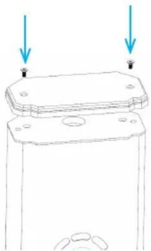
- Install the decorative cover of the wall hanging according to the figure. Secure the cover using two (M6*25) screws.
natural_image
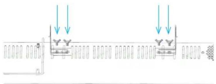
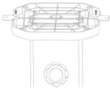
Technical line drawing of a mechanical component with two blue arrows pointing to features (no text or symbols)- Take out two hanging brackets, use 4 M6*16 butterfly tail screws to fix it, see figure as below:
- Fix the other two supports on the wall according to the distance of the support on the back of the heater, use a percussion drill to drill round holes with a diameter of 8 mm and a depth of about 40-50mm, insert four plastic wall anchors into the four holes, fix the supports with four ST4 * 35 self-tapping screws, and ensure that the installation point is firmly fixed.
Note: Wall distance parallel to the floor (at least 1.8 m from the floor and at least 0.5 m from the ceiling).

natural_image
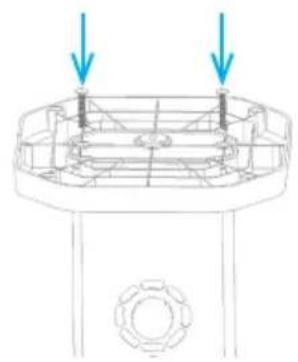
Mechanical assembly diagram showing two components with exploded view and mounting holes (no text or labels)- Use the rest 2 buterfully screw to fix the wall hanging bracket and heater hanging bracket, see pic as below.
Note: Please mind the heater direction before fixing it.
Free-standing heater
| Part Qty Part Qty | |||
| M6*25 screws 2 Plastic expansion 2 | |||
| ST4*35 screws 2 ST4*12 countersunk self-tapping screws | 2 | ||
| Solid plates 2 |
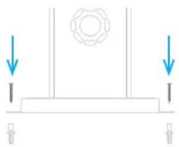
- Use the M6*25 Screw to fix the base.
natural_image
Technical line drawing of a mechanical component with two blue arrows pointing to features (no text or symbols)- Use the ST4*12 screw to fix the solid plate as below.

natural_image
Technical line drawing of a mechanical component with two blue arrows pointing to features (no text or symbols)- After driving the expansion tube into the ground, align the hole of the ground fixing sheet with the expansion tube, and drive the 4*35 tapping screws in the fitting bag into the expansion tube.
natural_image
Pure diagram of a mechanical or structural component with two downward arrows and a central circular feature (no text or symbols)Control panel Remote control
natural_image
Technical line drawing of a circular mechanical component with six symmetrical slots and a central hole (no text or symbols)
natural_image
Pure electrical control panel diagram without any text, numbers, or symbolsPower on and heat level setting
Plug in the heater. Eight red indicator lights will flash briefly.
Turn the knob to select the heat level from 1 to 8.
- Turn clockwise to increase the level.
- Turn counterclockwise to decrease the level.
Each red bar represents one power level. One bar lit = Level 1, and so on.
Timer Setting
Press the knob once. Eight green lights will start blinking. Turn the knob to set the timer from 1 to 8 hours.
• Each green bar represents one hour.
- The timer icon above will light up once a timer is set. After 5 seconds of no operation, the lights will switch back to red, showing the current power level.
Operation via remote control
Press the button to turn on the heater. Now the setting is power. Prese or to set the desired power level. Press the timer button, then press or to set the desired timer. After 5 seconds with no operation the timer setting will be closed.
MAINTENANCE AND CLEANING
Maintenance
- Caution! Careful and regular maintenance of the infrared heater is necessary to obtain a long and efficient operation of your appliance.
- Check the cleanliness of the reflector and IR filament at least once a month. If necessary, follow the cleaning and maintenance instructions.
- The number of checks may be increased depending on the amount of dust in the environment.
- During cleaning, visually inspect the reflector, wire and frame for deformation. In case of deformation, consult a qualified technician.
- Visually inspect the power cord and plug while cleaning the fixture. If there is any deformation, consult a qualified technician.
- It is recommended that the reflector be replaced every 2 years for more efficient operation.
Cleaning
- Caution! Regular and careful cleaning will help your heater to work efficiently for many years.
- For your safety, unplug the power cord before cleaning the appliance.
- Using a slotted screwdriver, remove the front grid wire through the inlets on the frame.
- The reflector and filament should be cleaned with a soft cloth, soft brush or cool or dry air. The cloth may be damp, but never too wet, and the cleaning agent must not contain any chemicals.
- Do not use cleaning products that could damage the reflector (detergents, etc.).
- Replace the grille using a flat screwdriver.
DISPOSAL CONSIDERATIONS
natural_image
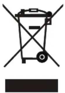
Symbol of a trash bin with crossed lines and a horizontal bar below (no text or labels)If there is a legal regulation for the disposal of electrical and electronic devices in your country, this symbol on the product or on the packaging indicates that this product must not be disposed of with household waste. Instead, it must be taken to a collection point for the recycling of electrical and electronic equipment. By disposing of it in accordance with the rules, you are protecting the environment and the health of your fellow human beings from negative consequences. For information about the recycling and disposal of this product, please contact your local authority or your household waste disposal service.
This product contains batteries. If there is a legal regulation for the disposal of batteries in your country, the batteries must not be disposed of with household waste. Find out about local regulations for disposing of batteries. By disposing of them in accordance with the rules, you are protecting the environment and the health of your fellow human beings from negative consequences.
MANUFACTURER & IMPORTER (UK)
Chal-Tec GmbH, Mühlenstrasse 25, 10243 Berlin, Germany. Contact: info@electronic-star.de
Chère cliente, cher client,
SOMMAIRE
Fiche technique 25
natural_image
Technical line drawing of a mechanical component with two arrows pointing to features (no text or symbols)natural_image
Mechanical assembly diagram showing two components with exploded view and mounting holes (no text or labels)natural_image
Technical line drawing of a mechanical component with two blue arrows pointing to features (no text or symbols)natural_image
Technical line drawing of a mechanical component with two blue arrows pointing to features (no text or symbols)natural_image
Pure diagram of a mechanical or structural component with two downward arrows and a central circular feature (no text or symbols)INSTRUCTIONS D'UTILISATION
natural_image
Technical line drawing of a circular mechanical component with six symmetrical slots and a central hole (no text or symbols)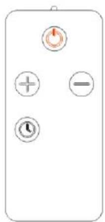
natural_image
Symbol of a trash bin with crossed lines and a horizontal bar below (no text or labels)INDICE
natural_image
Technical line drawing of a mechanical component with two blue arrows pointing to features (no text or symbols)natural_image
Mechanical assembly diagram showing two components with bolts and a central gear mechanism (no text or labels)natural_image
Technical line drawing of a mechanical component with no visible text or symbols

natural_image
Technical line drawing of a mechanical component with no visible text or symbols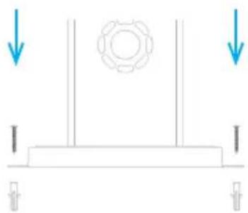
natural_image
Pure mechanical diagram showing a gear and support structure without any text, numbers, or symbolsISTRUZIONI PER L'USO
natural_image
Technical line drawing of a circular mechanical component with six symmetrical slots and a central hole (no text or symbols)
natural_image
Symbol of a trash bin with crossed lines indicating no waste or discharge, and a solid black rectangle below (no text or labels)ÍNDICE
Datos técnicos 45
natural_image
Technical line drawing of a mechanical component with two downward arrows indicating force or movement (no text or symbols)natural_image
Mechanical assembly diagram showing two components with bolts and shafts, no text or symbols presentnatural_image
Technical line drawing of a mechanical component with no visible text or symbols
natural_image
Technical line drawing of a mechanical component with no visible text or symbols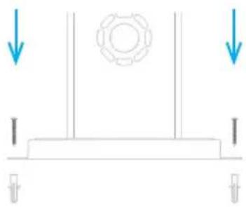
natural_image
Pure mechanical diagram showing a gear and support structure without any text, numbers, or symbolsINSTRUCCIONES DE USO
natural_image
Technical line drawing of a circular mechanical component with six symmetrical slots and a central hole (no text or symbols)
natural_image
Symbol of a trash bin with crossed lines indicating no waste or discharge, and a solid black rectangle below (no text or labels)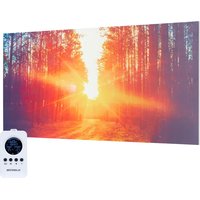

- INHALT
- BEDIENUNGSANLEITUNG
- CONTENTS
- SAFETY INSTRUCTIONS
- CAUTION
- Fire hazard
- Risk of burns
- Risk of personal injury
- INSTALLATION#
- Wall-mounted installation
- Free-standing heater
- Power on and heat level setting
- Timer Setting
- Operation via remote control
- MAINTENANCE AND CLEANING
- Maintenance
- Cleaning
- DISPOSAL CONSIDERATIONS
- MANUFACTURER & IMPORTER (UK)
- Chère cliente, cher client,
- SOMMAIRE
- INSTRUCTIONS D'UTILISATION
- INDICE
- ISTRUZIONI PER L'USO
- ÍNDICE
- INSTRUCCIONES DE USO
Brand : Klarstein
Model : DualisHeat
Category : Heating