
RS200i - Digital SLR Camera VirtuFit - Free user manual and instructions
Find the device manual for free RS200i VirtuFit in PDF.

| Product Type | Exercise Bike |
| Brand | VirtuFit |
| Model | RS200i |
| Dimensions (L × W × H) | 121 × 56 × 125 cm |
| Weight | 48 kg |
| Maximum User Weight | 150 kg |
| Power Supply | 2 AAA batteries (not included) |
| Display | LCD console with functions: Time, Speed, Distance, Calories, RPM, Heart Rate (BPM) |
| Console Functions | SCAN, target setting (time, distance, calories, heart rate), reset, alarm |
| Heart Rate Receiver | Wireless (Bluetooth) – compatible with external chest strap (not included) |
| Compatible Apps | Kinomap, iConsole+, Zwift (via Bluetooth) |
| Emergency Brake | Emergency brake button |
| Adjustments | Seat and handlebar adjustable in height and depth; leveling feet |
| Operating Temperature | 0 °C to 40 °C |
| Storage Temperature | -10 °C to 60 °C |
| Maintenance | Clean after each use; annual lubrication of moving parts with silicone spray |
| Safety | Use on flat, stable surface; clear space of 1 to 2 meters behind the equipment |
| Spare Parts | Available upon request (model number and serial number required) |
| Certifications | CE, EN ISO 20957, EMC (2014/30/EU), RoHS (2011/65/EU + 2015/863) |
| Warranty | Excludes damage due to improper use or non-compliance with maintenance |
Frequently Asked Questions - RS200i VirtuFit
User questions about RS200i VirtuFit
0 question about this device. Answer the ones you know or ask your own.
Ask a new question about this device
Download the instructions for your Digital SLR Camera in PDF format for free! Find your manual RS200i - VirtuFit and take your electronic device back in hand. On this page are published all the documents necessary for the use of your device. RS200i by VirtuFit.
USER MANUAL RS200i VirtuFit
natural_image
Technical illustration of a bolt with threaded fasteners and hexagonal bolts (no text or symbols)
D8x20 (4x)
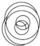

20×8.5×1.5 (4×)


25×10.5×2.0 (1×)
natural_image
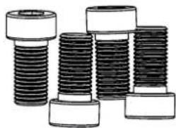
Illustration of multiple threaded fasteners or bolts (no text or symbols visible)
M8x12


∅8.5
natural_image
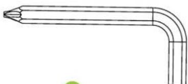
Line drawing of a bent tool or probe with pointed tip and curved handle (no text or symbols)
6mm (1x)

natural_image
Simple line drawing of a double-ended wrench (no text or symbols)
13-15 (1×)
STEP 1
STEP 2
STEP 3
STEP 4
STEP 5
STEP 6

FIG. A

INDEX
| Safety instructions | 11 | ||||
| Guarantee | 11 | ||||
| Assembly instructions 11 | |||||
| Adjusting | 11 | ||||
| Power supply | 12 | ||||
| Training with heart rate 12 | |||||
| Console overview | 13 | ||||
| Training with fitness applications 13 | |||||
| Maintenance | 14 | ||||
| Cleaning | 14 | ||||
| Troubleshooting | 14 | ||||
| Training guidelines | 14 | ||||
| Product specifications 15 | |||||
| Replacement parts | 15 | ||||
| Additional information 15 | |||||
| Declaration of the manufacturer 15 | |||||
SAFETY INSTRUCTIONS
WARNING!
Consult your doctor before you start exercising. This is particularly important for people with health problems. Please read all instructions before using the equipment. VirtuFit assumes no responsibility for injury or property damage resulting from the use of this equipment. Please read this manual carefully before assembling and/or using the equipment.
- Ensure the equipment is fully assembled and that all nuts and bolts are securely tightened before use.
- Lubricate all moving parts once a year using silicone spray.
- Avoid wearing loose clothing to prevent it from getting caught in moving parts.
- Place and use the equipment on a stable, level surface.
• Always wear clean sport shoes while using the equipment. - Keep children and pets at a safe distance during use.
- Maintain proper balance at all times while operating this equipment.
- Do not insert fingers or other objects into any moving parts.
- Consult your physician before beginning any exercise program to determine the appropriate frequency, duration, and intensity based on your age and physical condition. Discontinue use immediately if you experience nausea, dizziness, fainting, headache, chest pain, tightness, or any other discomfort.
- Do not move the equipment by holding it by the seat.
• The equipment is intended for use by one person at a time only.
- This equipment is designed for home use only and supports a maximum user weight of 150 kg.
- Allow 1–2 meters of clearance behind the equipment to prevent accidents.
- Place the equipment on a clean, flat surface. Do not use it on thick carpets, as this can obstruct proper ventilation. Avoid placing this equipment outdoors or near water.
- Keep the storage area clean, dry, and level to prevent damage to the equipment.
• Use this equipment exclusively for its intended purpose.
- Operate the equipment only in environments with an ambient temperature between 0°C and 40°C. Store the equipment in environments with a temperature between -10°C and 60°C.
GUARANTEE
Warranty claims are excluded if the cause of the defect is the result of:
- Maintenance and repair work not carried out by an official dealer.
- Improper use, negligence and/or poor maintenance.
- Failure to maintain the appliance in accordance with the manufacturer's instructions.
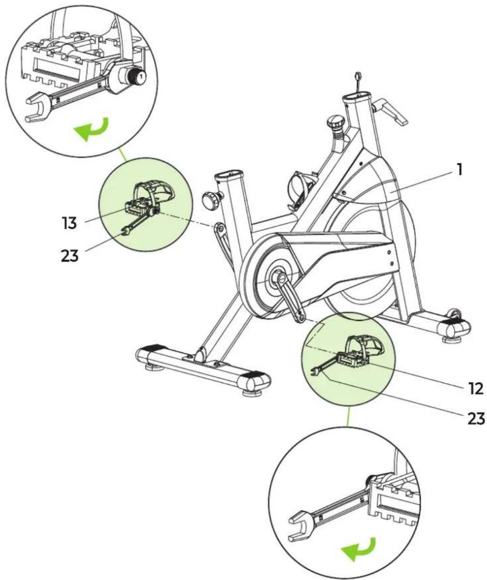
ASSEMBLY INSTRUCTIONS (STEP 1-6)
Missing parts: If any parts are missing from the packaging, carefully check the polystyrene foam and the appliance itself. Some parts (bolts, screws, etc.) are already attached to the unit.
Error message: Make sure that all cables are carefully attached. The brackets of the console are very sensitive and must be kept straight. If the console gives an error message after the equipment has been mounted, the brackets of the console may be bent. Straightening this aluminum part may make the error message disappear.
Hex head bolts: Make sure that the hex head spanner is pushed into the bolt before applying force. This will prevent the head of the socket bolt from turning.
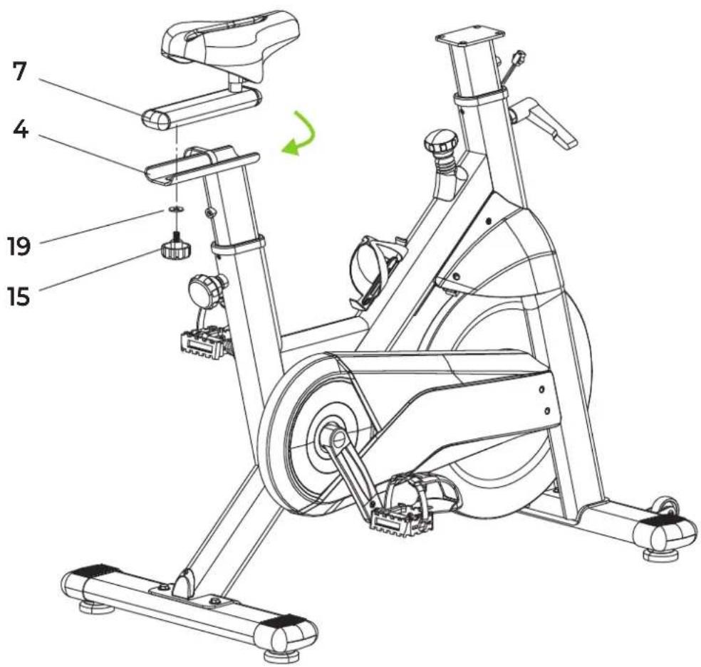
ADJUSTING
Adjusting the saddle (A)
To train effectively, it is advisable to adjust the saddle to the correct height. When pedalling, your knees should be slightly bent when the pedals are in their lowest position.
To adjust the saddle to the vertical position, follow the steps below:
- Loosen the seat post knob and pull the knob towards you.
- Slide the vertical seat post up or down until the saddle is at the desired seat height. Release the knob when the adjustment holes are aligned.
- Move the vertical seatpost slightly up or down to ensure the knob is in one of the adjustment holes.
• Tighten the seat post knob.
To adjust the saddle to the horizontal position, follow the steps below:
- Loosen the saddle knob a few turns.
- Slide the saddle forward or backward until it is in the desired position.
• Tighten the saddle knob.
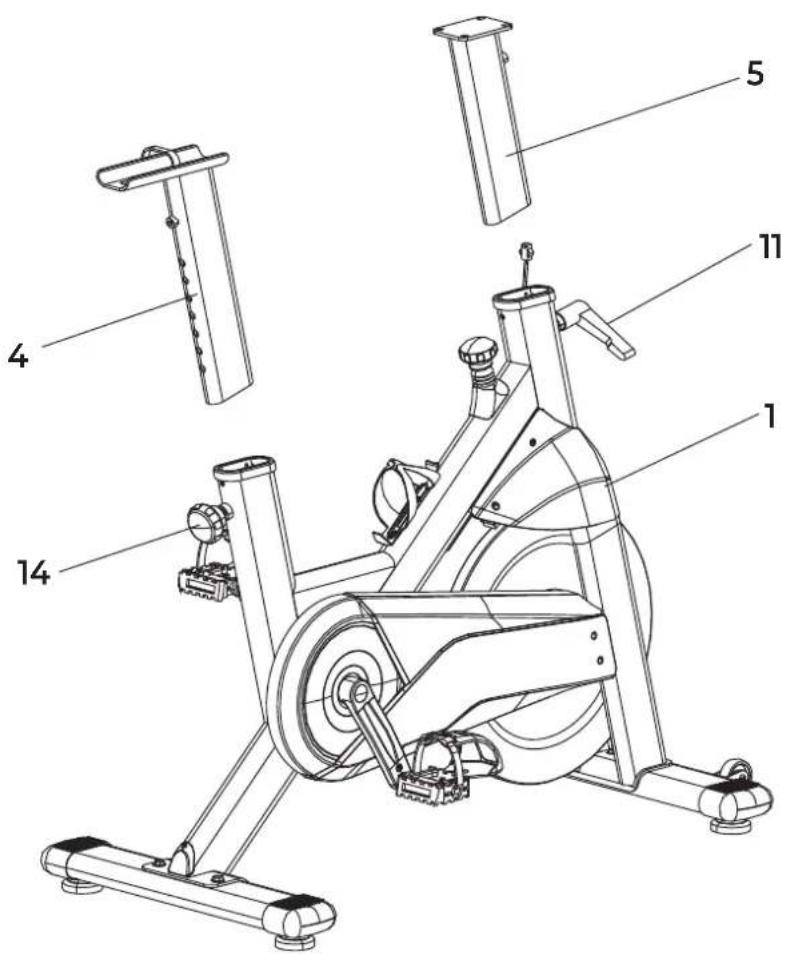
Adjusting the handlebars (B)
Follow the steps below to adjust handlebar height:
- Loosen the L-bolt.
- Move the handlebar post up or down within the main frame until the handlebar reaches the desired height. Ensure the adjustment holes are properly aligned before proceeding.
- Secure the handlebar in place by tightening the L-bolt.
Emergency brake (C)
The emergency brake is a safety feature designed to stop the spinbike immediately when required. Use the emergency brake whenever cycling must be halted without delay.
NOTE! To activate the emergency brake, press the emergency brake button (C) firmly.

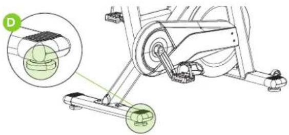
Leveling (D)
To ensure safe and stable use, always place the spin bike on a flat, solid surface. If necessary, a protective rubber mat may be placed underneath to improve grip and protect the floor.
If the surface is uneven, adjust the leveling feet located at the base of the spinbike. Turn the adjustable feet until the bike stands firmly and remains stable.
natural_image
Mechanical assembly diagram showing a rotating leg with two green circular components, one highlighted in an inset (no text or symbols present)POWER SUPPLY
AAA BATTERIES
The display uses AAA batteries, which are replaceable on the back of the display. The batteries must be inserted correctly.
If the screen is unreadable or only parts of the image work, proceed as follows:
- Remove the batteries and wait 15 seconds.
- Replace the batteries correctly.
Battery information
- Do not recharge, disassemble, or dispose batteries in a fire.
- Ensure correct polarity (+ and -) when inserting the batteries.
• Always replace all batteries at the same time; do not mix old and new batteries. - Use alkaline batteries for optimal performance and longer life.
- Replace the batteries when the display dims or becomes unresponsive.
Battery replacement
- If the display shows inaccurate readings, battery replacement is recommended.
- This device requires 2 × AAA batteries.
TRAINING WITH HEART RATE
Bluetooth
This VirtuFit fitness device is equipped with a wireless heart rate receiver. To measure your heart rate with a wireless heart rate monitor, use a heart rate monitor that works on Bluetooth. With a wireless heart rate monitor, it is important that the electrodes are slightly moist and the heart rate monitor fits well to your body. Refer to your heart rate monitor's user manual for proper instructions. Incorrect use of the heart rate monitor may result in abnormal readings.
NOTE! A wireless heart rate monitor is not included as standard. Contact your dealer to purchase a wireless heart rate monitor.
WARNING!
- If you have a pacemaker, we recommend that you consult your physician before using a wireless heart rate monitor.
- In rooms with multiple heart rate monitors, it is recommended that you keep enough distance to avoid interference between different devices.
· Always try to keep the wireless heart rate monitor within a range of 1 meter from the console for optimal reception.
· Always wear a wireless heart rate monitor directly on the body, under clothing.
CONSOLE OVERVIEW (FIG. A)

- SCAN: Automatic scan mode, cycles through all functions.
• TIME: Displays total exercise duration. - DISTANCE: Displays total training distance.
- CALORIES: Displays calories burned (estimate only).
- SPEED: Shows current training speed.
- ODO: Displays total accumulated distance.
• PULSE (BPM): Displays heart rate with signal input. - RPM: Displays pedal revolutions per minute.
- RESET: Resets all values to "0".
Console buttons
MODE
- Press to cycle through functions or lock one function. Each press is confirmed with a beep.
- Long press (2 seconds) resets all settings to "0".
SET
- Press to increase value.
- Hold to increase quickly.
• Time: 0:00–99:00 (1 min increments)
• Distance: 0.0–99.5 km (0.5 km increments)
• Calories: 0–9990 CAL (10 CAL increments) - Pulse: 30–230 BPM (1 BPM increments)
RESET
- Press once to clear the current value.
- Long press (2 seconds) resets all data to zero.
Functions
TIME
- When a target time is set, the console counts down.
- At 0:00, an alarm sounds 8 times, then the timer continues counting up.
- If no target is set, the timer will automatically count upward
SPEED Displays current speed automatically with signal input.
RPM Displays pedal revolutions per minute (RPM) automatically with signal input.
DISTANCE
- When a target distance is set (max. 99.5 km, increments of 0.5 km), the console counts down.
- At 0, an alarm sounds 8 times, then the distance continues counting up.
- If no target is set, the timer will automatically count upwards.
CALORIES
- When a target value is set (max. 9990 CAL, increments of 10), the console counts down.
- At 0, an alarm sounds 8 times, then calories continue counting up.
- If no target is set, the timer will automatically count upward
PULSE (BPM)
- Displays heart rate automatically with signal input.
- A target heart rate (30–230 BPM) can be set.
- If the heart rate exceeds the set value, an alarm will sound.
- Initial displayed value is 72 BPM until a signal is received.
TRAINING WITH FITNESS APPLICATIONS
VirtuFit does not provide service for third party fitness applications such as Kinomap, iConsole, FitShow etc. If you encounter problems with a third party fitness application, please contact the developer of the application in question.
Instruction
- Scan the QR code with an Android or iOS phone or tablet, to go directly to the App Store or Google Play Store page where the fitness app can be downloaded.
- Scan the QR code on the right to access the fitness app manual. The manual describes step by step how to connect the fitness app to the device, how the fitness app works and what its capabilities are.
iConsole+


APP STORE GOOGLE PLAY SUPPORT
Kinomap


APP STORE GOOGLE PLAY SUPPORT
Zwift


APP STORE GOOGLE PLAY SUPPORT
MAINTENANCE
Safe and effective use of this appliance is only possible when it is correctly installed and properly maintained. It is your responsibility to ensure the appliance is serviced regularly. Any worn or damaged parts must be replaced before resuming use. This equipment is intended for indoor use and storage only. Prolonged exposure to outdoor conditions or fluctuations in temperature and humidity may severely affect the electrical components and moving parts. Always disconnect the power cord before cleaning or performing any maintenance.
Daily maintenance
- Wipe down the unit after each use to remove sweat and moisture.
- Ensure the equipment is free from dust and dirt.
- Avoid using harsh cleaning agents and keep the equipment away from excessive moisture.
Semi-annual maintenance
- Inspect all bolts and nuts connected to moving parts. Tighten them if necessary.
- Check the movement of all mobile parts and components. Apply silicone spray if needed.
General cleaning recommendations
- Clean the unit after each training session.
- Use a dry cloth to clean the control panel.
- Use a soft, clean cloth with mild detergent to remove persistent stains and dirt.
- Store the equipment in a clean, dry environment, away from direct heat and water sources.
CAUTION! Repairs must be performed by a qualified technician, unless otherwise instructed by the supplier or manufacturer.
CLEANING
Regular cleaning significantly extends the lifespan of your equipment. Keep the appliance free from dust by cleaning it frequently.
Preventative maintenance not only prolongs the life of the equipment but also helps avoid potential injuries.
For more detailed information, visit: virtufit.com/faq
TROUBLESHOOTING
PROBLEM SOLUTION
| The display does not show any values | Check that all sensor and console cables are securely connected and undamaged. |
| If the problem persists, gently adjust the position of the sensor. | |
| Squeaking noise | Ensure that all bolts and nuts are properly tightened. |
| Lubricate moving parts if necessary. | |
| Ticking noise | This may be caused by incorrectly mounted pedals. |
| Firmly tighten the pedal(s). | |
| If the noise continues, remove and remount the pedals correctly:- The R (right) pedal must be mounted clockwise.- The L (left) pedal must be mounted counter-clockwise. | |
| If the problem persists, contact your supplier. | |
| Console is not responding | If no signal appears while pedaling, verify that the cable is correctly connected. |
TRAINING GUIDELINES
A successful training program includes a warm-up, the actual training and a cool-down. Perform the complete training program at least twice, but preferably three times a week and keep a rest day between training sessions. After a few months, the intensity of the training can be increased, for example to four or five times a week.
The warm-up
The purpose of a warm-up is to prepare the body for training and to reduce the risk of injury. Warm up your body for two to five minutes before starting a cardio or strength training session. Do exercises that increase the heart rate and warm up the working muscles. Examples of this type of activity are running, jogging, jumping jacks, skipping and running in place.
Stretching
Stretching while the muscles are warm is very important after a good warm-up and cool-down. It reduces the risk of injury. Stretching exercises should be held for 15-30 seconds.
Cooling down
The purpose of the cool-down is to return the body to its (near) normal resting position at the end of the workout. A good cool-down slowly reduces your heart rate and promotes recovery.
PRODUCT SPECIFICATIONS
Console specifications
| Time 00:00 - 99:59 | ||
| Speed 0.0 - 99.9 km/h | ||
| RPM 0 - 188 | ||
| Distance 0 - 99.99 km | ||
| Calories 0.0 - 9999 | ||
| BPM 30 - 230 | ||
| Battery type 2 x AAA | ||
| Operating temperature | 0^ C - 40^ C | |
| Storage temperature | - 10^ C - 60^ C | |
Technical data
| Length 121 cm | |
| Width 56 cm | |
| Height | 125 cm |
| Weight | 48 kg |
| Max. user weight | 150 kg |
REPLACEMENT PARTS
To request replacement parts for your VirtuFit equipment, please refer to the information on the front cover of this manual. In order to assist you efficiently, we kindly ask that you provide the following details when contacting our support team:
• The model number and serial number of the product
• The product name
- The part number and a clear description of the required part(s) (as listed in the parts list and shown in the exploded view section of this manual)
Providing accurate information will help us process your request quickly and effectively.
ADDITIONAL INFORMATION
Responsible disposal of packaging
At VirtuFit, we are committed to reducing environmental impact. We kindly ask that you recycle all packaging materials through designated recycling facilities, in line with national waste reduction initiatives.
Product disposal
Your VirtuFit equipment is built to deliver long-term performance and reliability. When the time eventually comes to retire the product, please ensure it is disposed of in accordance with the European WEEE Directive. This means taking the product to an authorized collection point for safe and environmentally responsible recycling.
DECLARATION OF THE MANUFACTURER
VirtuFit hereby declares that this product complies with the following standards and directives:
· EN ISO 20957
• EMC (2014/30/EU)
• RoHS (2011/65/EU + 2015/863)
As a result, the product is CE-certified.
VirtuFit
natural_image
Mechanical assembly diagram showing a rotating wheel and suspension mechanism, with no visible text or symbolsSTROOMVOORZIENING
AAA-batterijen
natural_image
Mechanical device diagram showing lever and shaft assembly with directional arrows (no text or symbols)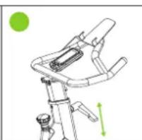
natural_image
Line drawing of a mechanical device with green arrows indicating motion or force direction (no text or symbols)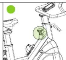
natural_image
Line drawing of a stationary bike with green circular markers highlighting the seat area (no text or symbols)Nivellierung (D)
natural_image
Mechanical assembly diagram showing a rotating vehicle with labeled components and a magnified inset view (no text or symbols present)STROMVERSORGUNG
AAA-BATTERIEN
natural_image
Mechanical assembly diagram showing a rotating leg with two green circular components, one highlighted in an inset view (no text or symbols present)ALIMENTATION ÉLECTRIQUE
PILES AAA
SPÉCIFICATIONS DU PRODUIT
natural_image
Mechanical assembly diagram showing a rotating leg with highlighted components (no text or symbols)natural_image
Mechanical assembly diagram showing a rotating leg with two green circular components, one enclosed in an inset view (no text or symbols)natural_image
Line drawing of a mechanical device with directional arrows indicating motion (no text or symbols)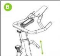
natural_image
Technical line drawing of a mechanical device with green directional arrows indicating motion (no text or symbols)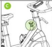
natural_image
Line drawing of a stationary bike with a green circular emblem on the seat (no text or symbols)Wyrównywanie (D)
natural_image
Mechanical assembly diagram showing a rotating wheel and base mount with green circular annotations highlighting specific components (no text or symbols present)ZASILACZ
BATERIE AAA
DODATKOWE INFORMACJE
natural_image
Mechanical assembly diagram showing a rotating leg mechanism with a close-up inset of the joint detail (no text or symbols present)NAPÁJENÍ
AAA baterie
natural_image
Mechanical diagram showing a stationary bike with two green circular components, one enclosed in an inset view (no text or symbols)ALIMENTARE CU ENERGIE ELECTRICĂ
BATERII AAA
natural_image
Diagram of a mechanical device with directional arrows indicating movement or force (no text or symbols)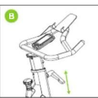
natural_image
Technical line drawing of a mechanical device with green directional arrows indicating motion (no text or symbols)
natural_image
Line drawing of a stationary bike with a green circular component highlighting the seat area (no text or symbols)Szintezés (D)
natural_image
Mechanical assembly diagram showing a rotating vehicle with labeled components and a magnified inset view (no text or symbols present)TÁPEGYSÉG
AAA ELEMEK
| # SKU DESCRIPTION QTY. | |||
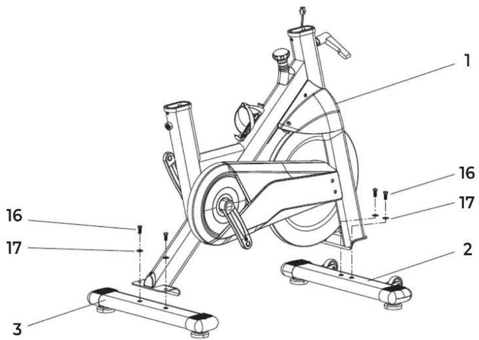
| 1 VFSP000917 | Main Body 1 | ||
| 2 VFSP000918 | Front Stabilizer 1 | ||
| 3 VFSP000919 | Rear Stabilizer 1 | ||
| 4 VFSP000920 | Saddle Post 1 | ||
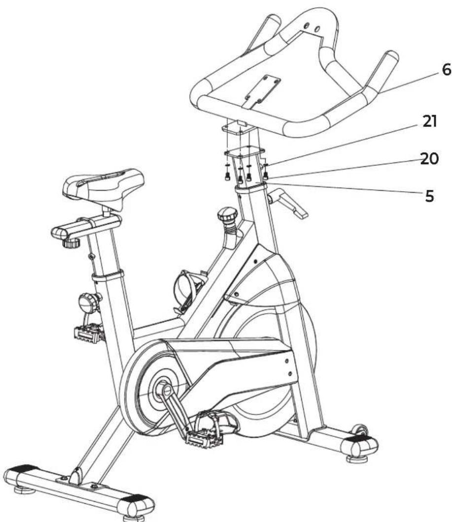
| 5 VFSP000921 | Handle Post | 1 | |
| 6 | VFSP000922 | Handle Frame | 1 |
| 7 | VFSP000923 | Saddle Adjustment Frame | 1 |
| 8 VFSP000924 | Saddle | 1 | |
| 9 | VFSP000925 | Monitor | 1 |
| 10 | VFSP000926 Phillips screw M5X10 | 2 | |
| 11 VFSP000927 | 7-shaped pull pin M16 | 1 | |
| 12 | VFSP000928 | Right pedal | 1 |
| 13 | VFSP000929 Left pedal | 1 | |
| 14 | VFSP000930 | Adjusting knob M16 | 1 |
| 15 VFSP000931 | Fixed knob M10 | 1 | |
| 16 | VFSP000932 | Hexagon socket screw M8X20 | 4 |
| 17 | VFSP000933 | Flat washer D8 | 4 |
| 18 | VFSP000934 | Signal Wire-A | 1 |
| 19 | VFSP000935 | Flat washer D10 | 1 |
| 20 | VFSP000936 | Hexagon socket screw M8X12 | 4 |
| 21 | VFSP000937 | Spring washer ∅8.5 | 4 |
| 22 | VFSP000938 | Signal Wire-B | 1 |
| 23 | VFSP000939 Open wrench 13-15 | 1 | |
| 24 | VFSP000940 | Inner hexagon spanner D5 | 1 |
| 25 | VFSP000941 Phone holder | 1 | |
| 26 | VFSP000942 Cap nut M8 2 | ||