
EP1100 - Electric planer SCHEPPACH - Free user manual and instructions
Find the device manual for free EP1100 SCHEPPACH in PDF.

| Product type | Electric planer |
| Brand | Scheppach |
| Model | EP1100 |
| Power supply | 220-230 V~ / 50/60 Hz |
| Power consumption | 1100 W |
| No-load speed | 16 000 min⁻¹ |
| Cutting depth | 0 to 3 mm (adjustable in 0.1 mm increments) |
| Groove depth | 0 to 18 mm |
| Planing width | 82 mm |
| Weight | 3.45 kg |
| Protection class | IP20 |
| Main functions | Surface planing, edge chamfering (45°), rebate planing with parallel stop |
| Included accessories | Chip bag, parallel stop, clamping key |
| Sound pressure level | 87 dB(A) |
| Sound power level | 98 dB(A) |
| Vibration emission value | 7.78 m/s² |
| Safety | Safety switch with lock, overload protection (automatic shutdown) |
| Maintenance | Cleaning after each use, replacement of reversible blades, replacement of drive belt |
| Wear parts | Carbon brushes, V-belt, planer blades |
| Warranty | Legal warranty on material or manufacturing defects (excluding labor) |
| Intended use | Planing wood (beams, boards) with workpiece held; chamfering; rebating |
Frequently Asked Questions - EP1100 SCHEPPACH
User questions about EP1100 SCHEPPACH
0 question about this device. Answer the ones you know or ask your own.
Ask a new question about this device
Download the instructions for your Electric planer in PDF format for free! Find your manual EP1100 - SCHEPPACH and take your electronic device back in hand. On this page are published all the documents necessary for the use of your device. EP1100 by SCHEPPACH.
USER MANUAL EP1100 SCHEPPACH
natural_image
Exterior view of a modern electric power tool (no visible text or symbols)EP1100
natural_image
Mechanical component diagram showing a piston-like structure with labeled part 'a' (no text or symbols beyond label)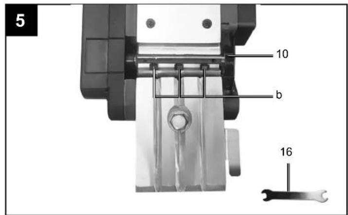
natural_image
Close-up of a mechanical power tool with labeled parts (fde), no readable text or symbols beyond the labelGünzburger Straße 69
D-89335 Ichenhausen
Verehrter Kunde
Explanation of the symbols on the device
Symbols are used in this manual to draw your attention to potential hazards. The safety symbols and the accompanying explanations must be fully understood. The warnings themselves will not rectify a hazard and cannot replace proper accident prevention measures.
 | Warning! Non-adherence poses a risk of death, danger of injury or the risk of damage to the tool! |
 | Before commissioning, read and observe the operating manual and safety instructions! |
 | Wear safety goggles! |
 | Wear hearing protection! |
 | If dust builds up, wear respiratory protection! |
 | Protection class IP20 |
Table of contents: Page:
- Introduction...... 18
- Device Description (Fig. 1)....18
- Scope of delivery.... 18
- Proper use....18
- Safety instructions....19
- Technical data 21
- Unpacking 21
- Assembly / Before commissioning 22
- Start up....22
- Electrical connection....23
- Cleaning and maintenance....23
- Storage....24
- Disposal and recycling 24
- Troubleshooting....25
1. Introduction
Manufacturer:
scheppach
Günzburger Straße 69
D-89335 Ichenhausen
Dear Customer
We hope your new tool brings you much enjoyment and success.
Note:
In accordance with the applicable product liability laws, the manufacturer of this device assumes no liability for damage to the device or caused by the device arising from:
- Improper handling
- Failure to comply with the operating instructions.
- Repairs carried out by third parties, unauthorised specialists
- Installing and replacing non-original spare parts,
- Improper use
- Failures of the electrical system in the event of the electrical regulations and VDE provisions 0100, DIN 57113 / VDE 0113 not being observed
Note:
Read the whole text of the operating manual before assembly and commissioning.
This operating manual should help you to familiarise yourself with your device and to use it for its intended purpose.
The operating manual includes important instructions for safe, proper and economic operation of the device, for avoiding danger, for minimising repair costs and downtimes, and for increasing the reliability and extending the service life of the device.
In addition to the safety instructions in this operating manual, you must also observe the regulations applicable to the operation of the device in your country.
Keep the operating manual at the device, in a plastic sleeve, protected from dirt and moisture. They must be read and carefully observed by all operating personnel before starting the work.
The device may only be used by personnel who have been trained to use it and who have been instructed with respect to the associated hazards. The required minimum age must be observed.
In addition to the safety instructions in this operating manual and the separate regulations of your country, the generally recognised technical rules relating to the operation of such machines must also be observed.
We accept no liability for accidents or damage that occur due to a failure to observe this manual and the safety instructions.
2. Device Description (Fig. 1)
- Adjustment knob for cutting depth
- On/off switch
- Switch lock
- Rear base plate
- Belt cover
- Front base plate
- Sawdust ejection port
- Knurled knob for step depth scale
- Step depth scale
- Planing shaft cover
- Dust bag
- Knurled screw, long
- Knurled screw, short
- Parallel stop mount
- Parallel stop
- Spanner
3. Scope of delivery
- Electric hand plane
- Dust bag (11)
- Wing screws
- Parallel stop (15)
- Spanner (16)
- Operating manual
4. Proper use
The device is suitable for planing wood in the form of beams or boards or the like if the workpiece is held securely in a fixed position. The device is also suitable for chamfering edges and for rebating. Any other use or modification to the device shall be considered as improper use and could give rise to considerable risk of accident. The manufacturer will not accept liability for loss or damage arising from improper use.
The machine may only be used in the intended manner. Any use beyond this is improper. The user/operator, not the manufacturer, is responsible for damages or injuries of any type resulting from this.
An element of the intended use is also the observance of the safety instructions, as well as the assembly instructions and operating information in the operating manual.
Persons who operate and maintain the machine must be familiar with it and must be informed about potential dangers.
In addition, the applicable accident prevention regulations must be strictly observed.
Other general occupational health and safety-related rules and regulations must be observed.
The liability of the manufacturer and resulting damages are excluded in the event of modifications of the machine.
The machine may only be operated with original parts and original accessories from the manufacturer. The safety, operating and maintenance specifications of the manufacturer, as well as the dimensions specified in the technical data, must be observed.
Please observe that our equipment was not designed with the intention of use for commercial or industrial purposes. We assume no guarantee if the equipment is used in commercial or industrial applications, or for equivalent work.
5. Safety instructions
General power tool safety warnings
⚠ WARNING!
Read all safety warnings, instructions, illustrations and specifications provided with this power tool.
Failure to follow all instructions listed below may result in electric shock, fire and/or serious injury.
Save all warnings and instructions for future reference.
The term "power tool" in the warnings refers to your mains-operated (corded) power tool or battery-operated (cordless) power tool.
1) Work area safety
a) Keep work area clean and well lit. Cluttered or dark areas invite accidents.
b) Do not operate power tools in explosive atmospheres, such as in the presence of flammable liquids, gases or dust. Power tools create sparks which may ignite the dust or fumes.
c) Keep children and bystanders away while operating a power tool. Distractions can cause you to lose control.
2) Electrical safety
a) Power tool plugs must match the outlet. Never modify the plug in any way. Do not use any adapter plugs with earthed (grounded) power tools. Unmodified plugs and matching outlets will reduce risk of electric shock.
b) Avoid body contact with earthed or grounded surfaces, such as pipes, radiators, ranges and refrigerators. There is an increased risk of electric shock if your body is earthed or grounded.
c) Do not expose power tools to rain or wet conditions. Water entering a power tool will increase the risk of electric shock.
d) Do not abuse the cord. Never use the cord for carrying, pulling or unplugging the power tool. Keep cord away from heat, oil, sharp edges or moving parts. Damaged or entangled cords increase the risk of electric shock.
e) When operating a power tool outdoors, use an extension cord suitable for outdoor use. Use of a cord suitable for outdoor use reduces the risk of electric shock.
f) If operating a power tool in a damp location is unavoidable, use a residual current device (RCD) protected supply. Use of an RCD reduces the risk of electric shock.
3) Personal safety
a) Stay alert, watch what you are doing and use common sense when operating a power tool. Do not use a power tool while you are tired or under the influence of drugs, alcohol or medication. A moment of inattention while operating power toolsmay result in serious personal injury.
b) Use personal protective equipment. Always wear eye protection. Protective equipment such as a dust mask, non-skid safety shoes, hard hat or hearing protection used for appropriate conditions will reduce personal injuries.
c) Prevent unintentional starting. Ensure the switch is in the off-position before connecting to power source and/or battery pack, picking up or carrying the tool. Carrying power tools with your finger on the switch or energising power tools that have the switch on invites accidents.
d) Remove any adjusting key or wrench before turning the power tool on. A wrench or a key left attached to a rotating part of the power tool may result in personal injury.
e) Do not overreach. Keep proper footing and balance at all times. This enables better control of the power tool in unexpected situations.
f) Dress properly. Do not wear loose clothing or jewellery. Keep your hair and clothing away from moving parts. Loose clothes, jewellery or long hair can be caught in moving parts.
g) If devices are provided for the connection of dust extraction and collection facilities, ensure these are connected and properly used. Use of dust collection can reduce dust-related hazards.
h) Do not let familiarity gained from frequent use of tools allow you to become complacent and ignore tool safety principles. A careless action can cause severe injury within a fraction of a second.
4) Power tool use and care
a) Do not force the power tool. Use the correct power tool for your application. The correct power tool will do the job better and safer at the rate for which it was designed.
b) Do not use the power tool if the switch does not turn it on and off. Any power tool that cannot be controlled with the switch is dangerous and must be repaired.
c) Disconnect the plug from the power source and/or remove the battery pack, if detachable, from the power tool before making any adjustments, changing accessories, or storing power tools. Such preventive safety measures reduce the risk of starting the power tool accidentally.
d) Store idle power tools out of the reach of children and do not allow persons unfamiliar with the power tool or these instructions to operate the power tool. Power tools are dangerous in the hands of untrained users.
e) Maintain power tools and accessories. Check for misalignment or binding of moving parts, breakage of parts and any other condition that may affect the power tool's operation. If damaged, have the power tool repaired before use. Many accidents are caused by poorly maintained power tools.
f) Keep cutting tools sharp and clean. Properly maintained cutting tools with sharp cutting edges are less likely to bind and are easier to control.
g) Use the power tool, accessories and tool bits etc. in accordance with these instructions, taking into account the working conditions and the work to be performed. Use of the power tool for operations different from those intended could result in a hazardous situation.
h) Keep handles and grasping surfaces dry, clean and free from oil and grease. Slippery handles and grasping surfaces do not allow for safe handling and control of the tool in unexpected situations.
5) Service
a) Have your power tool serviced by a qualified repair person using only identical replacement parts. This will ensure that the safety of the power tool is maintained.
Additional safety instructions
Safety instructions for planes
a) Wait for the knife shaft to stop before putting the electric tool down. An exposed rotating knife shaft can catch the surface and cause a loss of control and serious injuries.
b) Hold the electric tool by the insulated gripping surfaces, as the knife shaft can hit its own connection cable. Contact with a live power line can also electrify metal device parts and lead to an electric shock.
c) Fasten and secure the workpiece to a stable base using clamps or other means. If the workpiece is held only by hand or against the body, it remains unstable, which may result in a loss of control.
Safety advice relating specifically to power plan-ers
- Do not place your fingers in the planer debris removal port. Danger of injury from rotating parts.
- Always switch on the device before placing it against the workpiece. Otherwise you could be injured if the plane tilts.
- When working always keep the sole flat against the workpiece. Otherwise, you could be injured if the surface tips.
- Never plane over metal objects. Otherwise the planer blade / blade shaft could be damaged.
- Do not plane materials containing asbestos. Asbestos is a known carcinogen.
- The dust generated while planing could be hazardous to health, inflammable or explosive. Wear a dust mask and use a suitable dust / debris vacuum extraction device. Some dusts are known carcinogens.
- When planing wood for long periods and in particular when working on materials that give rise to dusts that are hazardous to health, the planer must be connected to a suitable external dust extraction device.
- Do not use the power planer if its mains lead is damaged. Damaged mains leads increase the risk of electric shock.
- Always arrange for the replacement of the plug or the power cord to be carried out by the manufacturer of the appliance or by his approved customer services. This ensures that safety of the electric tool is maintained.
- Never support yourself by placing your hands near or in front of the device or on the workpiece surface.
- If a dangerous situation arises, pull the mains plug immediately out of the mains socket.
- When taking a break from your work, before carrying out any tasks on the device itself (e.g. changing the plane blade) or when you are not using the device, always pull the mains plug out of the mains socket.
• Always work with the mains lead leading away from the rear of the device. - Use sharp planer blades only.
- Do not soak the materials or the surface you are about to work on with liquids containing solvents.
- Avoid contact with rotating parts.
- Never use the device for a purpose for which it was not intended or with non-original parts / accessories.
- Hold the device securely when working. Ensure that you are standing in a stable, well-balanced position.
• Always keep the device clean, dry and free from oil or grease.
Original accessories / attachments
- Use only the accessories and attachments detailed in the operating instructions. The use of attachments or accessories other than those recommended here could lead to you suffering an injury.
ATTENTION!
This electric tool generates an electromagnetic field during operation. This field can impair active or passive medical implants under certain conditions. In order to prevent the risk of serious or deadly injuries, we recommend that persons with medical implants consult with their physician and the manufacturer of the medical implant prior to operating the machine.
Residual risks
Even when this electric tool is operated properly, residual risks still remain. The following hazards may arise in connection with the design and construction of this electric tool:
- Lung damage if suitable dust protection mask is not worn.
- Hearing damage if suitable hearing protection is not worn.
- Damage to health resulting from hand/arm vibration if the device is used over an extended period of time or if it is not properly operated and maintained.
- Health hazard due to electrical power, with the use of improper electrical connection cables.
- Before performing setting or maintenance work, release the start button and pull out the power plug.
• Furthermore, despite all precautions having been met, some non-obvious residual risks may still remain. - Residual risks can be minimised if the “Safety Instructions” and the “Intended Use” together with the operating manual as a whole are observed.
- Avoid accidental starting of the machine: the operating button may not be pressed when inserting the plug in an outlet. Use the tool that is recommended in this operating manual. This is how to ensure that your machine provides optimum performance.
- Keep your hands away from the working area when the machine is in operation.
6. Technical data
Mains voltage 220-230 V\~ / 50/60 Hz
| Power input | 1100 W |
| Idling speed | 16000 min^ |
| Cutting depth | 3 mm |
| Rebate depth | 0 - 18 mm |
| Plane width | 82 mm |
| Protection class | IP20 |
| Weight | 3,45 kg |
Technical changes reserved!
Noise & vibration
⚠ Warning: Noise can have serious effects on your health. If the machine noise exceeds 85 dB (A), please wear suitable hearing protection.
Noise data
The total noise values determined in accordance with EN 62841.
Sound power level L_WA 98 dB(A)
Sound pressure level L_pA .....87 dB(A)
Uncertainty K_wa/pA 3 dB(A)
Wear hearing protection.
Excessive noise can result in a loss of hearing
Vibration parameters
Total vibration values (vector sum - three directions) determined in accordance with EN 62841.
Vibration emission value a_h 7,78 m/s ^2
Uncertainty K_h .....1,5 m/s ^2
The vibration emission value specified has been measured in accordance with a standardised test procedure and may change depending on the type and manner in which the electric tool is used and may be above the specified value in exceptional cases.
The specified vibration emission value can be used to compare one electric tool with other.
The specified vibration emission value can also be used for an initial assessment of the impairment.
7. Unpacking
- Open the packaging and carefully remove the device.
- Remove the packaging material, as well as the packaging and transport safety devices (if present).
- Check whether the scope of delivery is complete.
- Check the device and accessory parts for transport damage.
- If possible, keep the packaging until the expiry of the warranty period.
- Familiarise yourself with the product by means of the operating instructions before using for the first time.
- With accessories as well as wearing parts and replacement parts use only original parts. Replacement parts can be obtained from your dealer.
- When ordering please provide our article number as well as type and year of manufacture for your equipment.
ATTENTION!
The device and the packaging material are not children's toys! Do not let children play with plastic bags, films or small parts! There is a danger of choking or suffocating!
8. Assembly / Before commissioning
ATTENTION!
Always make sure the device is fully assembled before commissioning!
Before connecting the machine, make certain that the data on the type plate matches with the mains power data.
Warning!
Always pull out the mains plug before carrying out adjustments on the device.
8.1 Adjusting the cutting depth (Fig. 1)
The cutting depth can be adjusted in steps of 0.1 mm in a range of 0 - 3 mm by turning the cutting depth adjusting knob (1).
Turn the setting knob for the chip depth (1) in a clockwise direction to set a greater chip depth. Greater chip depth
Turn the setting knob for the chip depth (1) in a counter-clockwise direction to set a lower chip depth. Lower chip depth
After finishing work, set the chip depth so that the knives are lowered and thus protected from damage. Turn the setting knob for the chip depth to position "0" for this purpose.
8.2 Fitting the dust bag (Fig. 2)
Push the dust bag (11) onto the ejection port (7).
Note!
The dust bag (11) must always be fitted when using the device.
8.3 Parallel stop (Fig. 3)
Use the parallel stop (15) to plane parallel to the edge of the workpiece.
Fitting the parallel stop:
- Fasten the parallel stop mount (14) onto the left side of the device with the long knurled screw (12).
- Screw the parallel stop (15) to the parallel stop mount (14) with the short knurled screw (13).
9. Start up
ATTENTION!
Always make sure the device is fully assembled before commissioning!
9.1 ON/OFF switch (Fig. 1)
- The hand-held electric plane comes with a safety switch which is designed to prevent accidents.
- To switch on the tool, press the side safety lock-off (2) and press the button switch (3).
- Release the button switch (3) to switch off the electric plane. The button switch (3) jumps back into its starting position.
9.2 Practical tips
Warning!
Only ever bring the hand-held electric plane towards the workpiece while switched on.
9.2.1 Planing surfaces
- Now adjust the desired chip depth.
- Equip the front base plate and place the hand-held electric plane onto the piece of wood you whish to plane. Then switch on the plane.
- Push to electric plane over the surface with both hands and make sure that the both the front and the rear base plate lie flat on the workpiece.
- Used a low chip depth for finishing surfaces and complete several passes over the surface.
9.2.2 Chamfering edges (Fig. 4)
- There are three V-shaped grooves (a) in the front base plate that enable you to plane edges at an angle of 45^ for a smooth finish. You can choose from three different sizes of V-shaped grooves (a).
- Switch on the tool and wait until it reaches full speed. Place the required V-shaped groove (a) on the edge of the workpiece at an angle of 45^ .
- Now move the electric plane along the edge of the workpiece.
- To achieve a good quality result you should keep the feed speed and angle constant.
9.2.3 Planing steps (Fig. 1 / 3)
- The planing of steps is possible with the help of the parallel stop (15).
- Mount the parallel stop (15) on the left side of the tool.
- To mount the depth stop, fasten the step depth scale (9) to the front right side of the plane housing with the locking lever (8).
- Release the locking lever (8) and position the step depth scale (9) so that the required step depth is displayed. Pull the locking lever (8) tight again.
Width of step:
You can set the width of the step with the parallel stop (15).
Depth of step:
We recommend you to set a cutting depth of 2 mm and to keep planing the workpiece until the required depth of step is reached.
10. Electrical connection
The electrical motor installed is connected and ready for operation. The connection complies with the applicable VDE and DIN provisions.
The customer's mains connection as well as the extension cable used must also comply with these regulations.
Important information
In the event of overloading, the motor will switch itself off. After a cool-down period (time varies) the motor can be switched back on again.
Damaged electrical connection cable
The insulation on electrical connection cables is often damaged.
This may have the following causes:
- Pressure points, where connection cables are passed through windows or doors.
- Kinks where the connection cable has been improperly fastened or routed.
- Places where the connection cables have been cut due to being driven over.
- Insulation damage due to being ripped out of the wall outlet.
- Cracks due to the insulation ageing.
Such damaged electrical connection cables must not be used and are life-threatening due to the insulation damage.
Check the electrical connection cables for damage regularly. Ensure that the connection cables are disconnected from electrical power when checking for damage.
Electrical connection cables must comply with the applicable VDE and DIN provisions. Only use connection cables with the designation H05VV-F.
The printing of the type designation on the connection cable is mandatory.
AC motor
- The mains voltage must be 220-230 V\~.
- Extension cables up to 25 m long must have a cross-section of 1.5 mm ^2 .
Connections and repair work on the electrical equipment may only be carried out by electricians.
Please provide the following information in the event of any enquiries:
- Type of current for the motor
• Machine data - type plate - Machine data - type plate
11. Cleaning and maintenance
Attention!
Pull out the mains plug before performing any setting, maintenance or servicing work.
△ Have tasks that are not described in this operating manual performed by a specialist workshop. Use only original parts. Let the device cool down before all maintenance and cleaning tasks. There is a risk of burns!
Each time before using the device, check it for obvious defects such as loose, worn or damaged parts, or that screws or other parts are tight. Replace damaged parts.
11.1 Cleaning
We recommend that you clean the device directly after every use.
Wipe swarf and dust off the machine from time to time with a cloth.
Do not use cleaning agents or solvents. Chemical substances could damage the plastic parts of the device. Never clean the device under running water.
Clean the device at regular intervals using a damp cloth and a little soft soap. Make sure that no water can penetrate the device interior.
- Clean the device thoroughly after each use.
- Clean the ventilation holes and the surface of the device with a soft brush or cloth.
- Remove swarf, dust and dirt with a vacuum cleaner if necessary.
- Lubricate the moving parts regularly.
11.2 Servicing
11.2.1 Changing the planing knives (Fig. 5) Danger!
Always pull the plug out of the power socket before doing any work on the equipment.
The hand-held electric plane comes with two carbide metal reversible knives. Reversible knives have two cutting edges and can be reversed. The guide slot on the reversible knives ensures the same height setting after a change. Replace a worn, blunt or damaged knife.
- Loosen the three hex. screws (b) with the spanner (16) provided.
- Press the belt cover (10) downwards.
- Pull the complete blade holder out sideways.
- Slide the reversible blade sideways out of the blade holder with a block of wood.
Clean the knife seat before fi tting. Install the knives in reverse order. Check that the planing knife conforms with both ends of the planing shaft. Always replace both knives to ensure a uniform chip depth.
Danger!
Before using the hand-held electric plane make sure the knives are installed securely and in the right place.
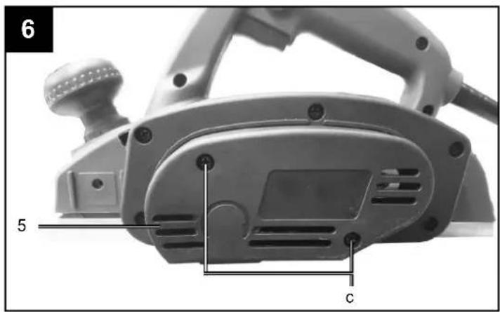
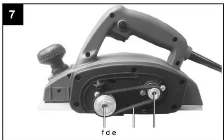
11.2.2 Replacing the drive belt (Fig. 6 / 7)
The belt should be replaced by a trained expert. The drive belt (d) must be replaced if it is worn.
- Undo the screws (c) and remove belt cover at the sides (5).
- Remove the worn belt drive (d) and clean the two belt pulleys (f/e).
- Place the new drive belt on the small belt pulley (e) and pull the belt onto the large belt pulley (f) whilst turning the planing shaft.
- Ensure that the longitudinal grooves on the drive belt are in the guide grooves on the drive wheels.
- Fit the belt cover (5) and secure it with the screws (c).
Service information
With this product, it is necessary to note that the following parts are subject to natural or usage-related wear, or that the following parts are required as consumables.
Wear parts*: Carbon brushes; V-belts, planing blades * may not be included in the scope of supply!
12. Storage
Store the device and its accessories in a dark, dry and frost-free place that is inaccessible to children. The optimum storage temperature lies between 5 and 30 °C.
Store the tool in its original packaging.
Cover the tool to protect it from dust or moisture. Store the operating manual with the tool.
13. Disposal and recycling
The device is supplied in packaging to avoid transport damages. This packaging is raw material and can thus be used again or can be reintegrated into the raw material cycle.
The device and its accessories are made of different materials, such as metals and plastics. Take defective components to special waste disposal sites. Check with your specialist dealer or municipal administration!
Do not throw old equipment away with household waste!

This symbol indicates that this product must not be disposed of in household waste as per Waste Electrical and Electronic Equipment directive (2012/19/EU) and national laws. This product must be handed over at the intended collection point. This can be done, for example, by returning it when purchasing a similar product or delivering it to an authorised collection point for the recycling of old electrical and electronic devices. Improper handling of old devices can have negative effects on the environment and on human health due to potential hazardous materials which are often contained in old electrical and electronic devices. By disposing of this product properly, you are also contributing to the effective use of natural resources. Information about collection points for old devices can be found at your municipal authority, the local disposal provider, an authorised location for the disposal of old electrical and electronic devices or your waste collection service.
14. Troubleshooting
The following table shows fault symptoms and describes remedial measures in the event of your machine failing to work properly. If you cannot localise and rectify the problem with this, please contact your service workshop.
| Fault Possible cause Remedy | ||
| Device does not start | No power supply Check the power connection and the socket. | |
| Triggered overload protection Allow the engine to cool down. | ||
| On/off switch defective Repair by an authorised service centre. | ||
| Motor defective Repair by an authorised service centre. | ||
| Motor stops during operation | Triggered overload protection Allow the engine to cool down. | |
| Motor defective Repair by an authorised service centre. | ||
| Unclean cut | Screws or parts of the electric tool are loose. | Tighten up all the screws. |
| The planing blades are not properly inserted. | Insert the planing blades correctly. | |
| The planing blades are worn. Check the planing blades. Turn the worn planing blades or replace them. | ||
Günzburger Straße 69
D-89335 Ichenhausen
Cher client,
Günzburger Straße 69
D-89335 Ichenhausen
Vážený zákazníku,
Günzburger Straße 69
D-89335 Ichenhausen
Vážený zákazník,
9.2.3 Hobl'ovanie stupňov (obr. 1/3)
Günzburger Straße 69
D-89335 Ichenhausen
Kedves Ügyfelünk!
Günzburger Straße 69
D-89335 Ichenhausen
Szanowny Kliencie,
CE - Declaration of Conformity
ELEKTRO-HANDHOBEL - EP1100
ELECTRIC
RABOTEUSE
5902801901
HAND PLANE
ÉLECTRIQUE
- EP1100 À MAIN
| 2014/29/EU | 2004/22/EC | 89/686/EC_96/58/EC | 2000/14/EC_2005/88/EC | ||||
| 2014/35/EU | 2014/68/EU | 90/396/EC | Annex V | ||||
| X | 2014/30/EU | X | 2011/65/EU* | Annex VINoise: measured L_WA = xx dB(A); guaranteed L_WA = xx dB(A)P = xx KW; L/∅ = cmNotified Body:Notified Body No.: | |||
| X 2006/42/EC | |||||||
| Annex IVNotified Body:Notified Body No.:Certificate No.: | 2010/26/EC | ||||||
| Emission. No: | |||||||
Standard references:
EN 62841-1:2015+AC:2015; EN 62841-2-14:2015; EN 55014-1; EN 55014-2; EN 61000-3-2; EN 61000-3-3
This declaration of conformity is issued under the sole responsibility of the manufacturer.
The object of the declaration described above fulfils the regulations of the directive 2011/65/EU of the European Parliament and Council from 8th June 2011, on the restriction of the use of certain hazardous substances in electrical and electronic equipment.
Apparent defects must be notified within 8 days from the receipt of the goods. Otherwise, the buyeris rights of claim due to such defects are invalidated. We guarantee for our machines in case of proper treatment for the time of the statutory warranty period from delivery in such a way that we replace any machine part free of charge which provably becomes unusable due to faulty material
or defects of fabrication within such period of time. With respect to parts not manufactured by us we only warrant insofar as we are entitled to warranty claims against the upstream suppliers. The costs for the installation of the new parts shall be borne by the buyer. The cancellation of sale or the reduction of purchase price as well as any other claims for damages shall be excluded.