
SS-21840 - Fan Sogo - Free user manual and instructions
Find the device manual for free SS-21840 Sogo in PDF.

| Brand | Sogo |
| Model | SS-21840 |
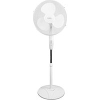
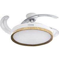
| Product Type | Ceiling fan with LED lighting |
| Supply Voltage | 220-240 V ~ 50/60 Hz |
| Power | 32 W |
| Number of Speeds | 6 |
| Reversible Function | Yes (summer/winter) |
| Integrated Lighting | Yes, LED CCT (3 colors) |
| Color Temperatures | Cool white, Daylight, Warm white |
| Color Memory | Yes |
| Remote Control | Yes, wireless |
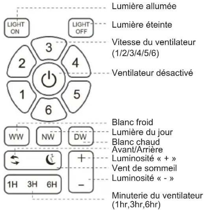
| Timer | Yes (1H, 3H, 6H) |
| Sleep Wind Mode | Yes |
| Minimum Mounting Height | 2.3 m |
| Minimum Distance to Walls | 76 cm |
| Anchor Point Load Capacity | Minimum 45 kg |
| Protection | Earthing mandatory |
| Use | Indoor only |
| Cleaning | Soft dry cloth, no water or detergent |
| Maintenance Frequency | At least once a year |
| Repairs | By certified electrician, original parts |
| Included Accessories | Balancing kit, remote control holder |
| Compliance | Low Voltage Directive 2014/35/EC, EMC, RoHS |
| After-Sales Service | www.sogosat.com / sogosat@sogosat.com |
Frequently Asked Questions - SS-21840 Sogo
User questions about SS-21840 Sogo
0 question about this device. Answer the ones you know or ask your own.
Ask a new question about this device
Download the instructions for your Fan in PDF format for free! Find your manual SS-21840 - Sogo and take your electronic device back in hand. On this page are published all the documents necessary for the use of your device. SS-21840 by Sogo.
USER MANUAL SS-21840 Sogo
ES Instructions for use
FR Mode d'emploi
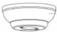
natural_image
Modern white and gray overhead air conditioner with a circular ceiling light (no text or symbols visible)
Descarga tu manual
Download your manual
- Important Note P. 16
- Safety instructions for the user P. 16
I. General precautions P. 16
II. Installation Instructions P. 18 - Technical specifications P. 22
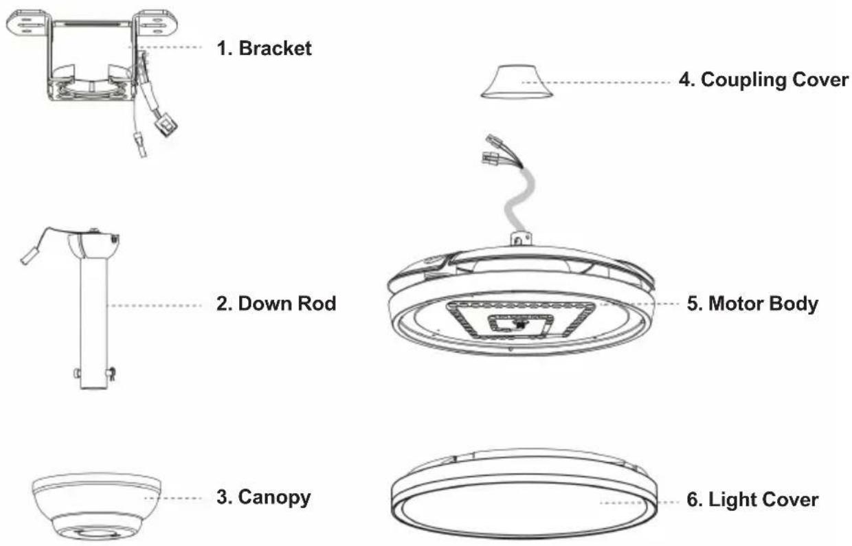
- Parts description P. 22
- Assembly instructions P. 23
- Instructions for use P. 26
- Cleaning and maintenance P. 28
ÍNDICE
natural_image
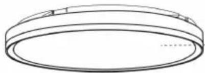
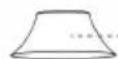
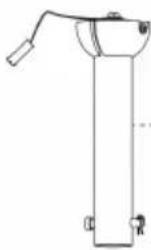
Technical line drawing of a mechanical assembly with no visible text or symbols- Soporte
natural_image
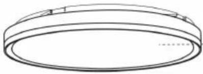
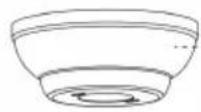
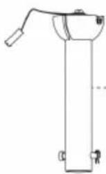
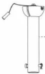
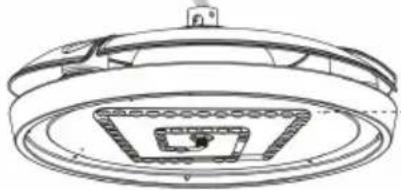
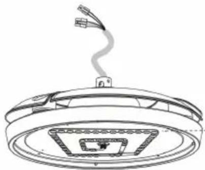
Technical line drawing of a circular device with internal components and a hanging cable (no text or symbols)- Cuerpo del motor
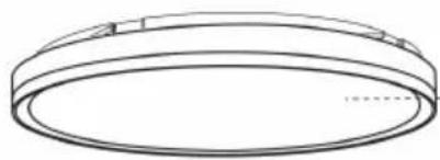
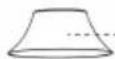
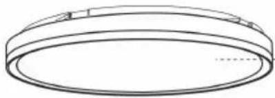
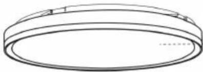
3. Toldo

natural_image
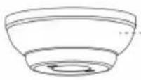
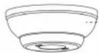
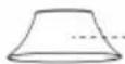
Simple line drawing of a circular object with a flat top and a horizontal seam, no text or symbols present.- Cubierta superior
natural_image
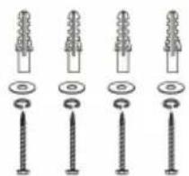
Five different types of screw and nut components shown in line drawings (no text or symbols)natural_image
Simple line drawing of an open book with a lowercase 'i' symbol on the right page (no text or labels)5. INSTRUCCIONES DE MONTAJE
natural_image
Diagram of a robotic arm and its internal components, showing motion from left to right (no text or labels)natural_image
Technical line drawing of a mechanical component with a curved pipe and two mounting holes (no text or symbols)natural_image
Technical line drawing of a mechanical device with a tool and base, no visible text or symbols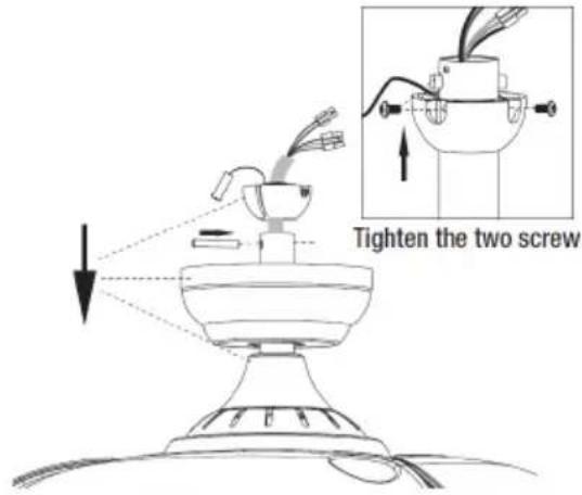
A. Techo de cemento

natural_image
Technical diagram showing screw installation components and a close-up of a mechanical assembly (no text or labels)natural_image
Technical diagram of a mechanical assembly with no visible text or symbols
natural_image
Line drawing of a hand connecting a mechanical component to a bracket (no text or symbols)3. Cableado
natural_image
Diagram of a funnel being inserted into a tube, with arrows indicating direction (no text or symbols)natural_image
Technical line drawing of a mechanical component with a top and bottom views (no text or symbols)IMPORTANT:
• Always read the instruction book carefully before using.
- This manual can be downloaded from our webpage www.sogo.es
- Keep these instructions for future reference.
SAFETY INSTRUCTIONS FOR THE USER General Precautions:
- Do not use the appliance for any other purpose than described in this manual.
- This product is intended for indoor, non-industrial, non-commercial and only for household use. Do not use the item outdoors or for any other purpose. Misuse or improper handling may cause problems in the appliance and cause injury to the user.
- Ensure that the voltage indicated on the nameplate matches the mains voltage before plugging in the appliance.
- Never use accessories that are not recommended by the manufacturer.
- The use of accessories not recommended or sold by the appliance manufacturer may result in fire, electric shock or injury to persons
- Do not use the appliance if the cable or plug is damaged. In case of the cord be damaged, it must be replaced only by the manufacturer, its service agent or similarly qualified persons in order to avoid Hazard.
• In case of appliance malfunction, or if it has
been damaged in any manner, return the appliance to the nearest authorized service facility for examination, repair or adjustment.
- In case of hardware problems, do not attempt to repair the product yourself. Repairs should only be carried out by qualified technicians.
- Turn the fan OFF when not in use and before disassembling or cleaning. Fully assemble the fan before switching on again.
- WARNING: To reduce the risk of personal injury, do not bend the blade brackets (also referred to as “flanges”) during assembly or after installation. Do not insert objects in the path of the blades.
- To avoid personal injury or damage to the fan and other items, be cautious when working around or cleaning the fan. Do not use water or detergent when cleaning the fan or fan blades. A dry dust cloth or lightly dampened cloth will be suitable for most cleaning.
- The appliance is not to be used by persons (including children) with reduced physical, sensory or mental capabilities, or lack of experience and knowledge, unless they have been given supervision or instruction.
- This appliance can be used by children aged from 8 years and above and persons with reduced physical, sensory or mental capabilities or lack of experience and knowledge if they have been given supervision or instruction concerning use of the appliance in a safe way and understand the hazards involved.
• Children should be supervised to ensure that they do not play with the appliance.
- Cleaning and user maintenance shall not be made by children.
- Keep the appliance and its cord out of reach of children less than 8 years.
- Do not allow the children to use the appliance without supervision.
Installation Instructions
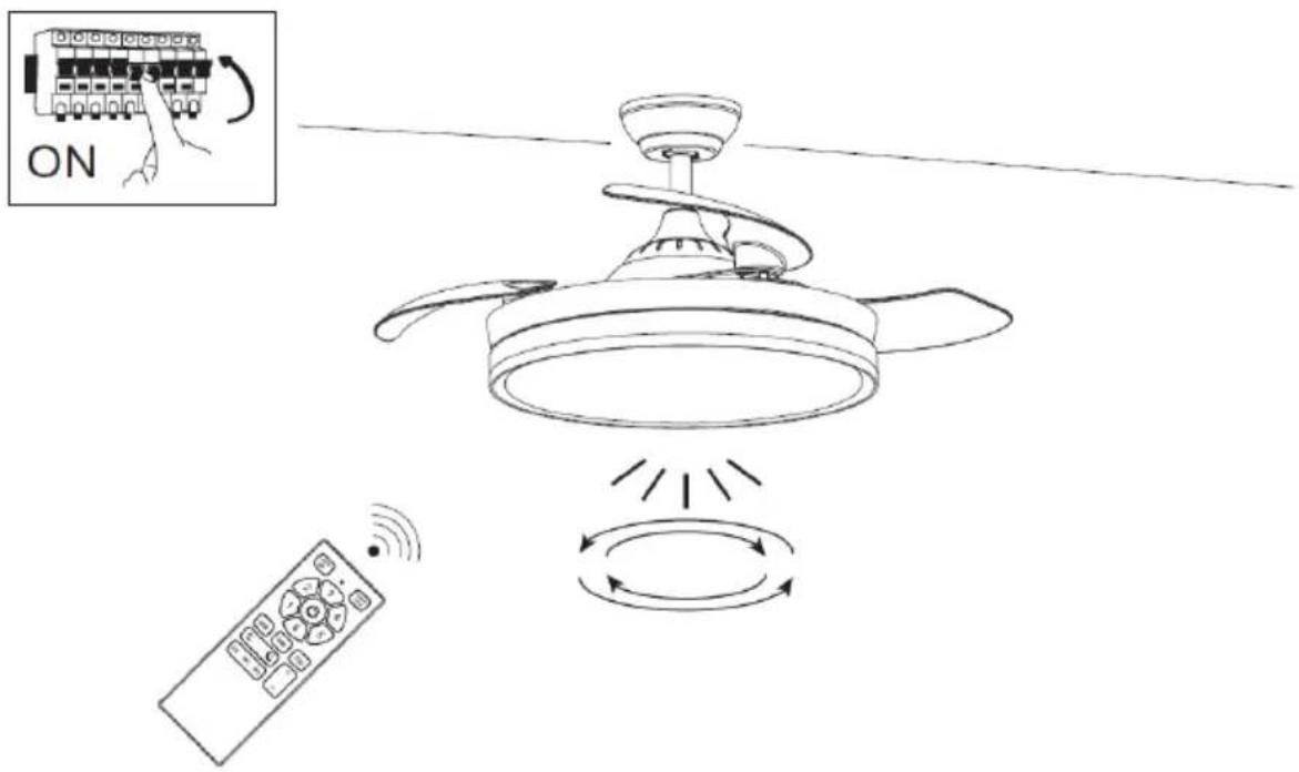
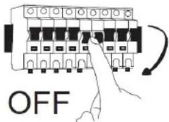
Please remove the fuse or turn off the circuit breaker to cut off the power before installing the fan. Ensure all electrical connections are in compliance with local laws, regulations and national electrical codes. If you are not familiar with electrical installation and wiring, please hire a qualified electrician or consult the wiring manual.
- For your safety, all electrical connections and disconnections should be performed by a qualified electrician.
- Any action performed for the electrical connection of the device must be carried out after ensuring that the general power supply is disconnected, by removing the corresponding fuse or disarming the protective switch in order to ensure total isolation of the power supply.
- When deciding where to mount the fan, be sure that there is at least 30 inches (76 cm) of space between the fan and any wall or other obstruction that the fan blades could
collide with. The greater this distance, the more effective the air flow produced. After the fan is mounted, be sure that the blades are no less than 7.8 ft (2.3 m) above the ground.
- The anchor point for the fan must be able to support a weight of at least 100 pounds (45 kg). If mounting on a ceiling junction box, be sure that the fan is adequately supported to prevent loosening or turning.
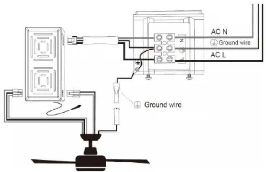
- The fan's electrical connection must be "grounded" (the fan's ground cable connected to the installation's grounding network) in order to avoid any branching that may be dangerous to people.
- Do not connect the fan's power supply to any dimmers, potentiometers, or light switches, as it will cause the fan to malfunction and/or will damage the motor. The fan must be directly connected to a properly protected installation circuit (magneto thermal differential switch with the adequate size for the fan's consumption and technical specifications). Only use the fan's control to turn it on or stop it.
- It is recommended to not use these types of fans along with gas installations simultaneously in the same room.
- The fan must not be moving at all and must have come to a complete stop before changing its direction of rotation. This will prevent damage to its motor and to the control unit, when applicable.
- Do not insert anything that could hit the
fan's blades into its pathway while it is moving, as this could cause damage to people, can damage the blades, and can offset the balance of the unit, causing vibrations and wobbling.
-
After installing the fan, ensure that all fastenings are secure and tightened in order to avoid any noise caused by loose elements.
-
Due to the fan's movement, certain fastenings may become loose. Check all fastenings twice per year at a minimum in order to ensure that they are sufficiently tight. If necessary, they must be retightened.
-
The motor housing can be cleaned with a soft brush or a lint-free cloth to avoid scratching the surface. Clean the blades with a lint-free cloth. Important: Turn off the main power supply before starting any maintenance. Do not clean the fans with water or a damp cloth.
-
WARNING: If unusual oscillating movement is observed, immediately stop using the ceiling fan and contact the manufacturer, its service agent or suitably qualified persons.
-
That the replacement of parts of the safety suspension system device shall be performed by the manufacturer, its service agent or suitably qualified persons.
-
Stationary appliances not fitted with means for disconnection from the supply mains having a contact separation in all
poles that provide full disconnection under overvoltage category III, the instructions state that means for disconnection must be incorporated in the fixed wiring in accordance with the wiring rules.
- The fixing means for attachment to the ceiling such as hooks or other devices shall be fixed with a sufficient strength to withstand 4 times the weight of the ceiling fan.
- That the mounting of the suspension system shall be performed by the manufacturer, its service agent or suitably qualified persons;
Note: The important warnings and instructions indicated in this manual are not guaranteed to cover all possible conditions and situations that may occur. It must be understood that common sense, precaution, and care are factors that cannot be included in all products. These factors can and must only be provided by the user who maintains and enjoys this fan.
3. TECHNICAL SPECIFICATIONS
| Voltage Power Frequency | |
| 220-240V 32W 50-60Hz |
4. PARTS DESCRIPTION
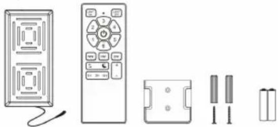
- Remote control unit (batteries not included)
- Blade balancing kit
natural_image
Illustration of various household appliances including a TV, remote control, battery pack, and two cylindrical batteries (no text or symbols)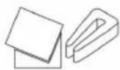
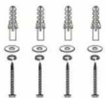
- Screw packaging 10. Installation Manual
natural_image
Five different types of screw and nut components shown in line drawings (no text or symbols)
natural_image
Simple line drawing of an open book with a lowercase 'i' symbol on the right page (no text or labels)5. ASSEMBLY INSTRUCTIONS
1. Basic Assembly of Fan
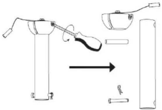
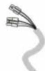
(1) Decompose Down rod
natural_image
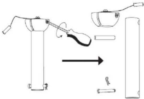
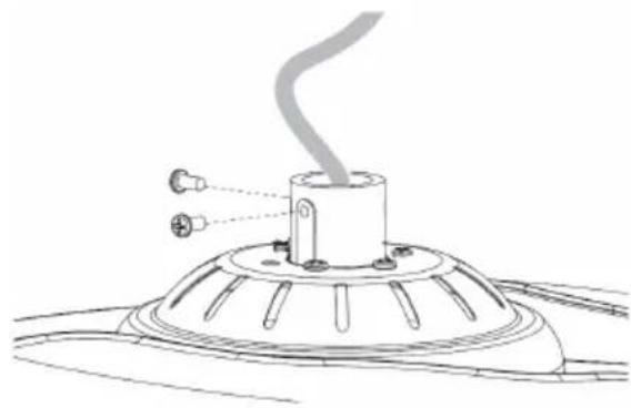
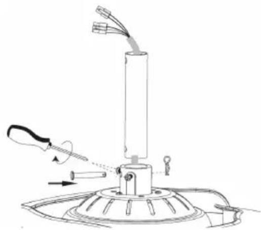
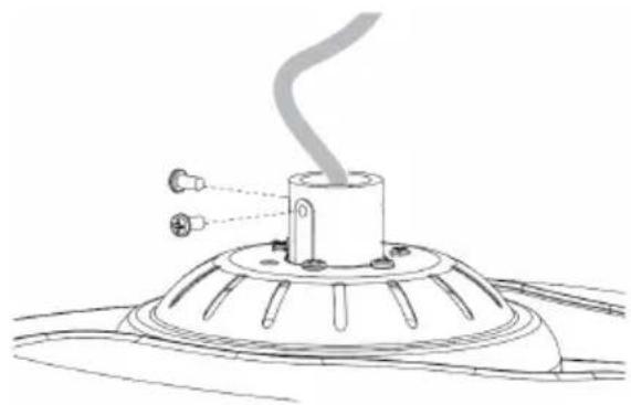
Diagram of a robotic arm and its internal components, showing motion from left to right (no text or labels)(3) Route all the wires through motor down rod. Fix the down rod to the coupling with the help of bolt and then insert the clevis pin. Tighten the 2 screws on coupling.
(2) Unscrews the 2 screws on coupling
natural_image
Technical line drawing of a mechanical component with a curved pipe and two mounting holes (no text or symbols)(4) Install the coupling cover and canopy, hanging ball. Insert the fixing pin, push the hanging ball up and fix it with screws.
natural_image
Technical line drawing of a mechanical device with a tool and base, no visible text or symbols
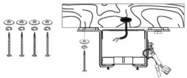
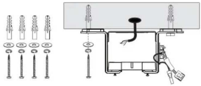
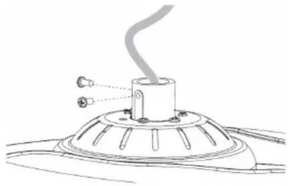
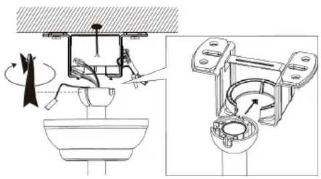
2. Bracket installing
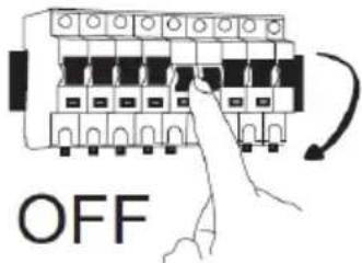
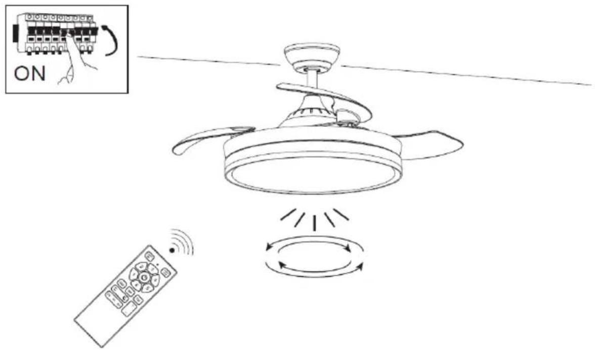
(1) Turn off the fan power supply at the circuit breaker box and wall switch.
Note: Failure to disconnect the power supply, prior to installation, might result in serious injury or death.
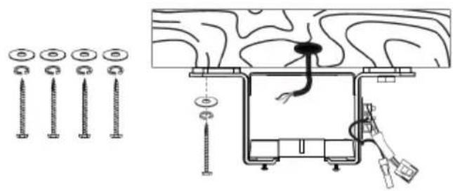
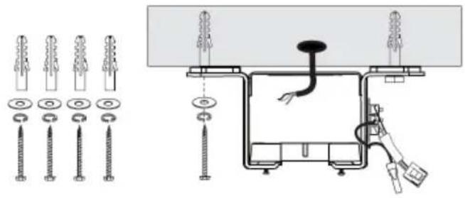
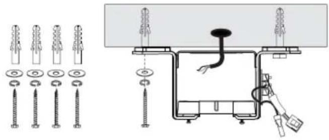
(2) If it is cement ceiling, please drill the installation hole at the installation location.
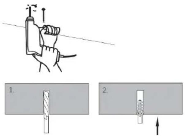
A. Cement ceiling
B. Solid wood ceiling
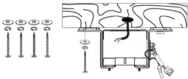
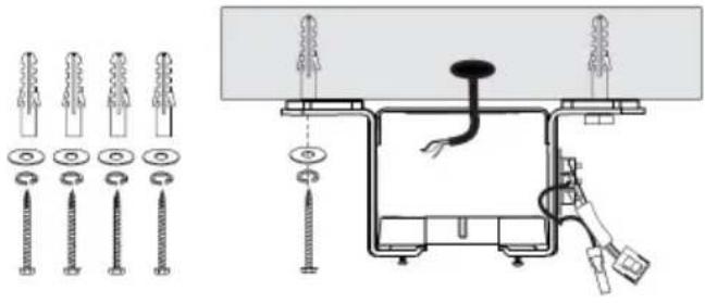
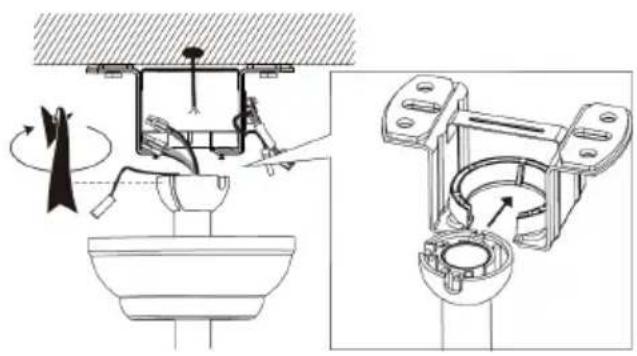
(3) Snap assembled fan into the installed bracket
(4) Put the receiver into the bracket and arrange the wires.
natural_image
Technical diagram of a bathroom fixture with mechanical components and directional arrows (no text or labels)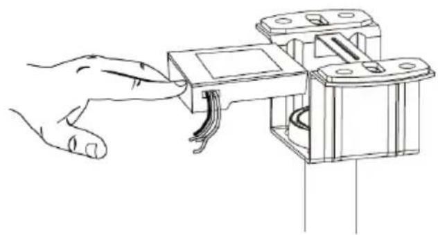
natural_image
Line drawing of a hand inserting a component into a mechanical housing (no text or symbols)3. Wiring
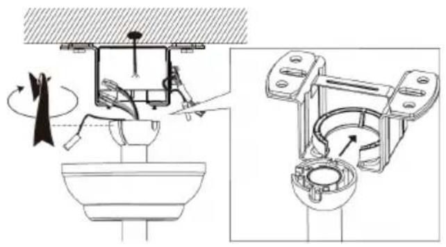
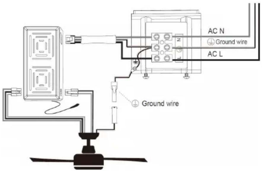
(1) Make the wire connection according to wiring diagram provided.
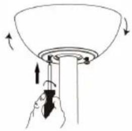
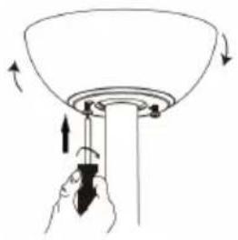
(2) Rotate the canopy clockwise until screw heads engage the key slots fully. Tighten the screws. Be careful not to damage or cut the wiring. Insert the decorative ring into canopy.
natural_image
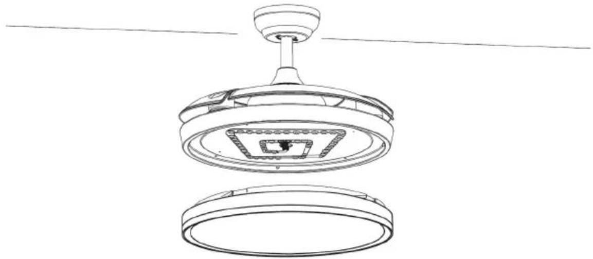
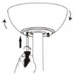
Diagram of a funnel with arrows indicating rotation and force application (no text or symbols)4. Installation of light kit
(1) Insert light cover..
natural_image
Technical line drawing of a ceiling-mounted device with a top and bottom views (no text or symbols)- Trial of fan switch working and remote-control functioning.
Note: this fan doesn't work without mounting all the blades. If the fan is turned on without installing the blades, the receiver will detect that the fan speed is too fast and fan will stop automatically.
6. INSTRUCTIONS FOR USE
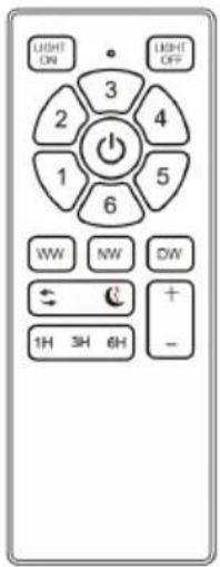
REMOTE CONTROL OPERATIONS
Remote control and receiver connection process:
- Insert the batteries into the remote control.
- Turn on the power supply of fan. Withing next 10 sec. press and keep pressed "1" and "2" button for about 3 seconds.
Note: This process is necessary to complete the connection process between remote control and receiver. - Once the receiver detects the remote-control frequency, receiver will beep twice and connection process is completed and fan is ready to use.
Note: Remote control has already been matched with receiver at the time of production, but still if you find that fan is not responding to the remote-control device, then keep repeating connection process.
REMOTE CONTROL HOLDER
INSTALLATION

REMOTE CONTROL FUNCTION
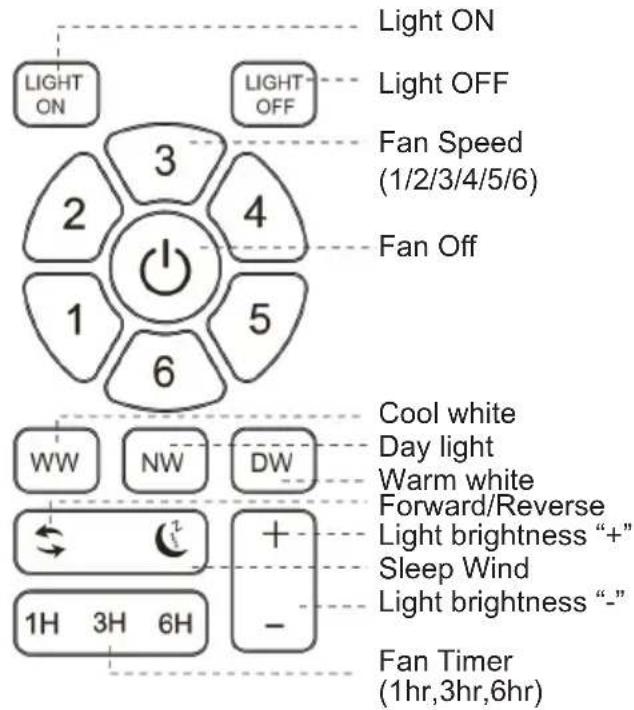
LIGHT FUNCTION
This unit works with CCT light function system, which allows us to choose light type as per our need. There are 3 colours of light type in this function.
- WW: Cool white light
- NW: Day light or normal light
- DW: Warm white light
In order to choose the type of light press the corresponding button and select the light as per need and desire.
LIGHT MEMORY FUNCTION
This fan has light colour memory function and, in this function, fan function with same light colour after turning on the fan again. In order to memorise the light colour, need to turn on the light and keep it for 3-5 seconds, turn off the fan and wait at least 10 seconds before turning on the fan again.
FAN WORKING MODES
This fan works with 2 working modes:
Normal Wind mode: In this normal wind mode fan operate normally and with 6 speeds.
Sleep wind mode: In this mode fan operate at a lower speed compared to its regular settings. This reduced speed generates less noise and making it suitable for use during sleep or quiet hours.
REVERSIBLE FUNCTION
Reversible fan is a type of fan that has the capability to change the direction of airflow. This means it can either push air forward or pull air backward, depending on the desired mode of operation. Below has been explained mechanism of reverse function.
- Forward mode: In this mode, the fan operates like a traditional fan, pushing air forward. This is the mode that we use during hot weather to circulate air and create a cooling effect. The blades of the fan rotate in a specific direction, usually anticlockwise, to push air forward.
- Reverse mode: In reverse mode, the fan reverses the direction of airflow, pulling air backward. This mode is often used during colder weather to help distribute warm air more evenly throughout a room. The blades of the fan rotate in the opposite direction, usually clockwise, to pull air backward.
The ability to switch between forward and reverse modes makes reversible fans versatile and suitable for use in various seasons and weather conditions. It allows for better control over airflow and temperature regulation within a space. These fans are commonly found in ceiling fans, window fans, and some portable fans, offering flexibility and convenience to users
DYNAMIC BLADE BALANCING KIT
How to rectify such problems:
- Ensure that all blades are firmly secured to the blade brackets.
- Ensure that all blades are firmly secured to the fan body and that the pitch of the blades are all same.
- From bottom of the fan, inspect the blades visually and ensure None of them are bent or out of line. If you notice a blade is not in the right position or pitch, gently bend the blade holder to the correct position.
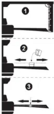
- If the fan is still unstable, the tracking of the blades must be checked using a measurement tape, measure the distance from the leading edge of the blade to the ceiling. Ensure this is the same for all blades and if necessary, make small adjustments by gently bending the blade.
If by following all the above steps your fan is still unstable, then the dynamic blade balancing kit must be used.
- Turn the fan on and adjust to the highest speed setting
- Turn the fan off, select a blade and place the balancing clip on to it, halfway between the tip of the blade and the end of the blade.
- Turn the fan on and observe if the wobble has improved.
- Repeat this step on all of the blades and make a note which blade boasted the greatest improvement.
- Place the clip back onto this blade & move up and down on to the length of the blade until you have found a spot that reduces the wobble.
• Install a balancing weight in this spot, ensuring you place the weight on the top face of the blade along the centre line. You may need to use a sharp knife to separate the weights. - Turn the fan on and check that it is now stable & operates fine.
CAUTTON: Stay away of moving blades. If the clip is not fixed properly on the blade for any reason, turn the fan off immediately. This might result in injury.
7. CLEANING AND MAINTENANCE
Cleaning:
- Before cleaning, turn the unit off, cut off the power supply from electrical outlet and wait for the unit to cool down.
- To clean the unit, use a soft cloth to wipe off any dust.
- Do not try to open the unit without a licensed electrician. Improperly installed the unit can be dangerous.
- Clean the unit at least once a year.
Maintenance:
- Have your product repaired by a licensed electrician
- This electric product is in accordance with the relevant safety requirements. Repairs should only be carried out by licensed electricians using original spare parts, otherwise this may result in considerable danger to the user.
- Please contact the store which you bought the product for after sale services if any.
TROUBLESHOOTING
| Fan does not work 1. Check all fuses or circuit breakers, if something disrupting the power supply to the fan.2. Turn off electrical power and check all wire connections to fan and in switch housing. It must be carried out by a electrician. | |
| Fan turns but airflow is inadequate | 1.The fan may be running in reverse, so air is going upward.2.The room may contain items that obstruct the air flow.3.The fan may be too small for size of the room. |
| Fan is noisy | 1. Make sure that the screws fastening blade arm to motor are tight and the lock washers provided for that purpose have been used.2. Lower the upper canopy to ensure a separation from the ceiling of no less than 3mm to reduce Noise.3. Check to see if any of the blades are cracked. If yes, replace all of the blades.4. If this is the first use, leave the fan on for at least 8 hours. If the mechanical noise continues after this period, contact certified electrician. |
Balancing – Wobbling problems during fan operation
If the fan body wobbles during its operation, this is not a sign of malfunctioning (even if it wobbles a few centimetres). To reduce wobbling, you can turn off the fan, and:
- Check that all blades are properly fastened by tightening their screws.
- Check the distance between each blade and the ceiling. Measurements to the ceiling can be carried out as shown in the following diagram. If variations exist and you have already correctly tightened the screws, check that all blades have the same shape. If any of them have a shape that is visibly different, this may be causing an imbalance during fan operation. If you have completed the previous steps and the wobbling has not resolved, you should apply dynamic balancing with the kit provided, as explained below:
- Turn the fan to the highest speed to generate the maximum amount of oscillation.
- Turn off the fan. Choose a random position of the leaf shelf plate (see picture) and put down the balance weight.
- Turn on the fan and check whether the swing has improved or worsened. Close it again, if the swing does not improve, please adjust the position of the balance weight. Repeat this process and determine the best position to reduce swing.
- Tear off the double-sided tape of the weighing block and stick it to the final position.
IMPORTANT:
natural_image
Technical line drawing of a mechanical device with mounting brackets and a cable (no text or symbols)- Support
natural_image
Line drawing of a ceiling-mounted appliance with a coiled cable and ventilation slots (no text or symbols)- Corps du moteur
3. Auvent
natural_image
Simple line drawing of a circular object with a flat top and a flat bottom, no text or symbols present.natural_image
Five different types of screw fasteners shown in line drawings, no text or symbols presentnatural_image
Simple line drawing of an open book with a lowercase 'i' symbol on the right page (no text or labels)5. INSTRUCTIONS DE MONTAGE
natural_image
Diagram showing a device with a lever and handle, moving through a cylindrical container (no text or symbols)natural_image
Technical line drawing of a mechanical component with a curved pipe and two mounting holes (no text or symbols)natural_image
Technical line drawing of a mechanical device with a tool and base, no visible text or symbols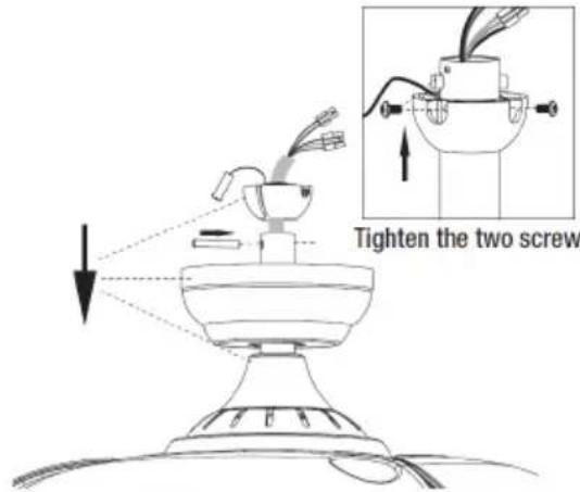
2. Installation du support
natural_image
Technical diagram showing screw installation components and a close-up of a mechanical assembly (no text or labels)natural_image
Technical diagram of a mechanical assembly with exploded and assembled views (no text or labels)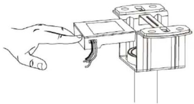
natural_image
Line drawing of a hand connecting a mechanical component to a bracket (no text or symbols)3. Câblage
natural_image
Diagram of a funnel being inserted into a cylindrical tube, with arrows indicating direction (no text or symbols)natural_image
Technical line drawing of a mechanical component with a top and bottom views (no text or symbols)FONCTION DE LA TÉLÉCOMMANDE
IMPORTANTE:
natural_image
Technical line drawing of a mechanical assembly with mounting brackets and a connector (no text or symbols)- Suporte
natural_image
Technical line drawing of a circular device with a suspended cable or cable connector (no text or symbols)- Corpo do motor
3. Dossel
natural_image
Simple line drawing of a circular object with a small protrusion, no text or symbols present.natural_image
Illustration of various household appliances including a TV, remote control, battery pack, and two batteries (no text or symbols)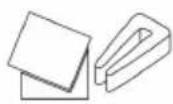
natural_image
Five different types of screw fasteners shown in line drawings, no text or symbols present
natural_image
Simple line drawing of an open book with a lowercase 'i' symbol on the right page (no text or labels)5. INSTRUÇÕES DE MONTAGEM
natural_image
Diagram showing a device being processed from a tool, with no visible text or symbolsnatural_image
Technical line drawing of a mechanical component with a curved pipe and two mounting holes (no text or symbols)natural_image
Technical line drawing of a soldering iron with a base, showing tool path and component placement (no text or symbols)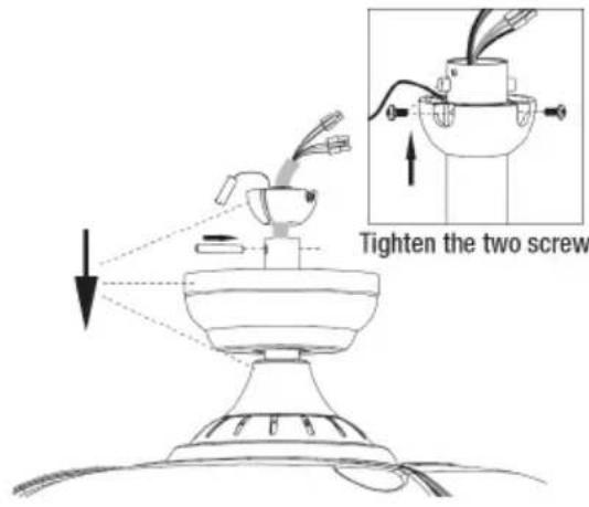
A. Teto de cimento

B. Teto de madeira maciça
(3) Encaixe a ventoinha montada no suporte instalado
natural_image
Technical diagram of a mechanical assembly with exploded and assembled views (no text or labels)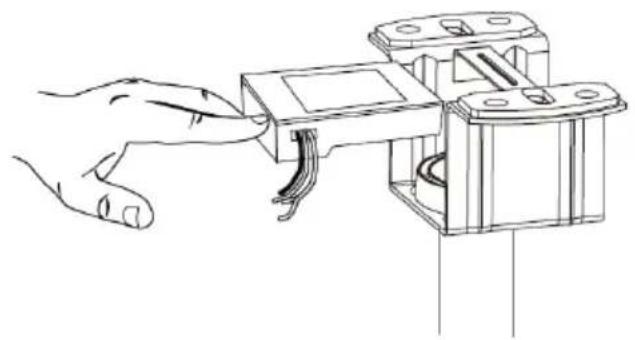
natural_image
Line drawing of a hand inserting a component into a mechanical housing (no text or symbols)3. Cablagem
natural_image
Diagram of a hand holding a tool interacting with a ceiling fan, showing airflow direction (no text or symbols)natural_image
Technical line drawing of a ceiling-mounted fan assembly with a top and bottom views (no text or symbols)WICHTIG:
natural_image
Illustration of various household appliances including a TV, remote control, battery pack, and two cylindrical batteries (no text or symbols)
natural_image
Five different types of screw fasteners shown in line drawings, no text or symbols present
natural_image
Simple line drawing of an open book with a lowercase 'i' symbol on the right page (no text or labels)5. MONTAGEANLEITUNG
natural_image
Diagram of a handheld device with lever mechanism and component layout (no text or symbols)natural_image
Technical line drawing of a mechanical component with a curved pipe and two protruding ports (no text or symbols)natural_image
Technical line drawing of a mechanical device with a tool and base, no visible text or symbols
A. Zementdecke

B. Massivholzdecke
natural_image
Technical diagram of a mechanical assembly with exploded and assembled views (no text or labels)
natural_image
Line drawing of a hand inserting a component into a mechanical housing (no text or symbols)3. Verkabelung
natural_image
Diagram of a funnel being inserted into a tube, with arrows indicating direction (no text or symbols)natural_image
Technical line drawing of a mechanical component with a top and bottom views (no text or symbols)IMPORTANTE:
natural_image
Illustration of various household appliances including a TV, remote control, battery pack, and two cylindrical batteries (no text or symbols)natural_image
Five different types of screw fasteners shown in line drawings, no text or symbols present
natural_image
Simple line drawing of an open book with a lowercase 'i' symbol on the right page (no text or labels)natural_image
Diagram of a robotic arm and its internal components, showing motion and assembly (no text or labels)natural_image
Technical line drawing of a mechanical component with a curved pipe and two mounting holes (no text or symbols)natural_image
Technical line drawing of a mechanical device with a tool and base, no visible text or symbols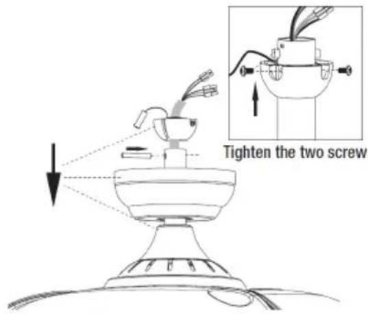
natural_image
Technical diagram showing screw installation components and a close-up of a mechanical assembly (no text or labels)natural_image
Technical diagram of a mechanical assembly with exploded and assembled views (no text or labels)
natural_image
Line drawing of a hand connecting a mechanical component to a bracket (no text or symbols)3. Cablaggio
natural_image
Diagram of a funnel being inserted into a tube, with arrows indicating direction (no text or symbols)natural_image
Technical line drawing of a mechanical component with a top and bottom views (no text or symbols)DŮLEŽITÉ
natural_image
Technical line drawing of a mechanical assembly with no visible text or symbols- Držák
4. Kryt spojky
- Dolní tyč

natural_image
Technical line drawing of a circular device with a suspended cable or cable outlet (no text or symbols)- Těleso motoru
3. Stříška
natural_image
Simple line drawing of a circular ring or washer (no text or symbols)natural_image
Five different types of screw fasteners shown in line drawings, no text or symbols present
natural_image
Simple line drawing of an open book with a lowercase 'i' symbol on the right page (no text or labels)5. MONTÁŽNÍ NÁVOD
natural_image
Diagram of a robotic arm and mechanical device with directional arrows indicating motion (no text or symbols)natural_image
Technical line drawing of a mechanical component with a curved pipe and two protruding pins (no text or symbols)natural_image
Technical line drawing of a mechanical device with a tool and base, no visible text or symbols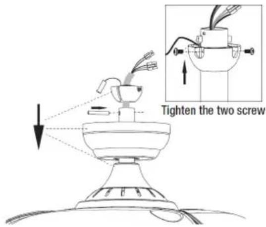
2. Instalace držáku
A. Cementový strop
natural_image
Technical diagram showing screw installation components and a close-up of a mechanical assembly (no text or labels)natural_image
Technical diagram of a mechanical assembly with exploded and assembled views (no text or labels)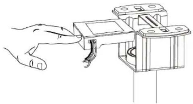
natural_image
Line drawing of a hand inserting a component into a mechanical housing (no text or symbols)3. Zapojení
natural_image
Diagram of a funnel being inserted into a handle, showing motion arrows (no text or symbols)natural_image
Technical line drawing of a ceiling-mounted device with a top and bottom views (no text or symbols)VIGTIGT:
natural_image
Illustration of various household appliances including a TV, remote control, battery pack, and two cylindrical batteries (no text or symbols)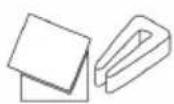
natural_image
Five different types of screw fasteners shown in line drawings, including threaded and flat screw designs (no text or labels)
natural_image
Simple line drawing of an open book with a lowercase 'i' symbol on the right page (no text or labels)5. MONTERINGSVEJLEDNING
natural_image
Diagram of a robotic arm and a cylindrical device with labeled parts, showing motion from left to right (no text or symbols)(2) Skru de 2 skruer på koblingen af.

natural_image
Technical line drawing of a mechanical component with a curved pipe and two mounting holes (no text or symbols)natural_image
Technical line drawing of a mechanical device with a tool and base, no visible text or symbols
A. Cementloft
natural_image
Technical diagram showing screw installation components and a close-up of a mechanical assembly (no text or labels)(3) Klik den samlede ventilator fast i det montere-de beslag.
natural_image
Technical diagram of a mechanical assembly with exploded and assembled views (no text or labels)
natural_image
Line drawing of a hand connecting a mechanical component to a bracket (no text or symbols)3. Ledningsføring
natural_image
Diagram of a funnel being inserted into a tube, with arrows indicating direction (no text or symbols)4. Installation af lyskit
natural_image
Technical line drawing of a mechanical component with a top and bottom views (no text or symbols)POMEMBNO:
natural_image
Illustration of various household appliances including a TV, remote control, battery pack, and two cylindrical batteries (no text or symbols)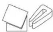
natural_image
Illustration of four different screw fasteners with different mounting holes (no text or symbols)
natural_image
Simple line drawing of an open book with a lowercase 'i' symbol on the right page (no text or labels)5. NAVODILA ZA MONTAŽO
1. Osnovna sestava ventilatorja
(1) Razgradite palico navzdol

natural_image
Diagram of a robotic arm and mechanical device with a curved tool, showing motion from left to right (no text or symbols)(3) Vse žice speljite skozi motorno palico navzdol. S pomočjo vijaka pritrdite spodnjo palico na sklopko in nato vstavite zatič. Privijte 2 vijaka na spojki.
(2) Odvijte 2 vijaka na spojki
natural_image
Technical line drawing of a mechanical component with a curved pipe and two protruding ports (no text or symbols)natural_image
Diagram of a soldering iron with a probe inserted into a base, showing mechanical components and motion direction (no text or labels)
A. Cementni strop
(3) Sestavljeni ventilator zataknite v nameščeni nosilec
(4) Vstavite sprejemnik v nosilec in uredite žice.
natural_image
Technical diagram of a mechanical assembly with exploded and assembled views (no text or labels)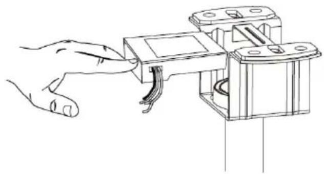
natural_image
Line drawing of a hand connecting a mechanical component to a bracket (no text or symbols)3. Ožičenje
(2) Zavrtite krošnjo v smeri urinega kazalca, dokler se glave vijakov v celoti ne zataknejo v reže za ključe. Zategnite vijake. Pri tem pazite, da ne poškodujete ali prerežete ožičenja. Okrasni obroč vstavite v krošnjo.
natural_image
Hand holding a tool interacting with a funnel-shaped object, no text or symbols visiblenatural_image
Technical line drawing of a mechanical component with a top and bottom views (no text or symbols)VAŽNO:
- Prije uporabe uvijek pažljivo pročitajte knjižicu s uputama.
- Ovaj priručnik možete preuzeti s naše web stranice www.sogo.es
- Čuvajte ove upute za buduću upotrebu.
SIGURNOSNE UPUTE ZA KORISNIKA
Opće mjere opreza:
natural_image
Illustration of various household appliances including a remote control, battery pack, and two cylindrical batteries (no text or symbols)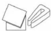
- Pakiranje vijaka 10. Priručnik za instalaciju
natural_image
Illustration of four different screw fasteners with different mounting holes (no text or symbols)
natural_image
Simple line drawing of an open book with a lowercase 'i' symbol on the right page (no text or labels)5. UPUTE ZA SASTAVLJANJE
1. Osnovni sklop ventilatora
(1) Rastaviti donju šipku
natural_image
Diagram of a robotic arm and its internal components, showing motion from left to right (no text or labels)(2) Odvrnite 2 vijka na spojnici
natural_image
Technical line drawing of a mechanical component with a curved pipe and two mounting holes (no text or symbols)(4) Ugradite poklopac spojnice i nadstrešnicu, viseću kuglu. Umetnite klin za pričvršćivanje, gurnite viseću kuglu prema gore i pričvrstite je vijcima.
(3) Provucite sve žice kroz motku motora. Pričvrstite donju šipku na spojnicu uz pomoć vijka, a zatim umetnite klin. Zategnite 2 vijka na spojnici.

natural_image
Technical line drawing of a mechanical device with a base, handle, and tool (no text or symbols)
2. Ugradnja nosača
(1) Isključite napajanje ventilatora na kutiji prekidača i zidnom prekidaču.
Napomena: Ako ne odspojite napajanje prije instalacije, to može dovesti do ozbiljnih ozljeda ili smrti.
A. Cementni strop

(3) Ugurajte sklopljeni ventilator u instalirani nosač
(4) Stavite prijemnik u nosač i rasporedite žice.
natural_image
Technical diagram of a mechanical assembly with exploded and assembled views (no text or labels)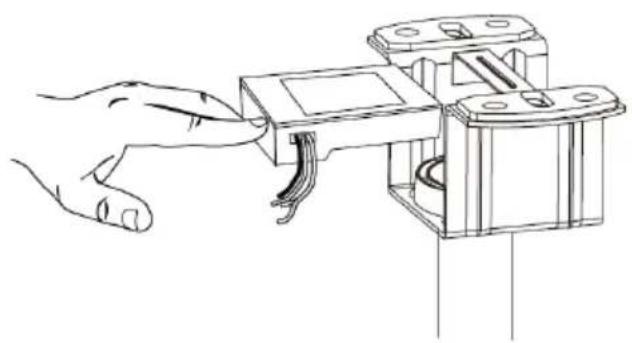
natural_image
Line drawing of a hand connecting a mechanical component to a bracket (no text or symbols)3. Ožičenje
(1) Spojite žicu prema priloženom dijagramu ožičenja.
(2) Okrećite nadstrešnicu u smjeru kazaljke na satu dok glave vijaka potpuno ne uđu u utore za ključeve. Zategnite vijke. Pazite da ne oštetite ili prerežete ožičenje. Umetnite ukrasni prsten u nadstrešnicu.
natural_image
Diagram of a funnel being inserted into a tube with arrows indicating direction (no text or symbols)natural_image
Technical line drawing of a mechanical component with a top and bottom views (no text or symbols)- Proba rada prekidača ventilatora i rada daljinskog upravljanja.
Napomena: ovaj ventilator ne radi bez montiranja svih lopatica. Ako se ventilator uključi bez instaliranja lopatica, prijemnik će detektirati da je brzina ventilatora prevelika i ventilator će se automatski zaustaviti.
6. UPUTE ZA KORIŠTENJE
OPERACIJE NA DALJINSKO UPRAVLJANJE
WAŻNE:
natural_image
Technical line drawing of a mechanical assembly with no visible text or symbols- Wspornik
4. Pokrywa sprzęgła
2. Pręt w dół
- Korpus silnika
natural_image
Technical line drawing of a circular mechanical component with a central recessed feature (no text or symbols)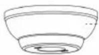
3. Daszek
natural_image
Simple line drawing of a circular object with a rectangular cutout and a dashed line indicating a dimension (no text or symbols)natural_image
Illustration of four different screw fasteners with different mounting holes (no text or symbols)natural_image
Simple line drawing of an open book with a lowercase 'i' symbol on the right page (no text or labels)5. INSTRUKCJA MONTAŻU
natural_image
Diagram of a mechanical device with labeled parts, showing a lever mechanism and assembly process (no text or symbols)natural_image
Technical line drawing of a mechanical component with a curved pipe and two mounting holes (no text or symbols)natural_image
Technical line drawing of a mechanical device with a base and tool, no visible text or symbols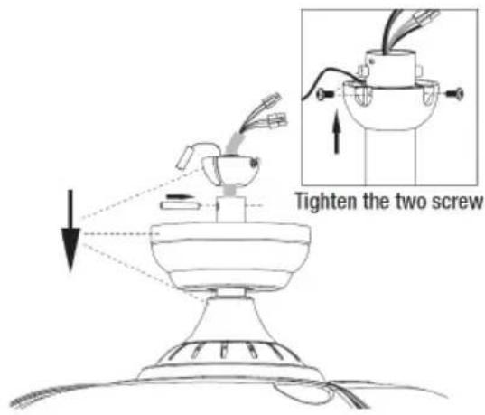
2. Montaż wspornika
A. Sufit cementowy

natural_image
Technical diagram showing screw installation components and a close-up of a mechanical assembly (no text or labels)natural_image
Technical diagram of a mechanical assembly with exploded and assembled views (no text or labels)
natural_image
Line drawing of a hand inserting a component into a mechanical housing (no text or symbols)3. Okablowanie
natural_image
Diagram of a funnel being inserted into a tube with arrows indicating direction (no text or symbols)natural_image
Technical line drawing of a ceiling-mounted device with a top and bottom views (no text or symbols)TRYBY PRACY WENTYLATORA
IMPORTANT
natural_image
Technical line drawing of a mechanical device with no visible text or symbols- Suport
4. Capacul de cuplare
- Tijă de
coborâre
natural_image
Technical line drawing of a circular device with internal components and a hanging cable (no text or symbols)- Corpul motorului

3. Baldachin
natural_image
Simple line drawing of a circular ring or washer (no text or symbols)natural_image
Five different types of screw fasteners shown in line drawings, no text or symbols present- Kit de echilibrare a lamei

natural_image
Simple line drawing of an open book with a lowercase 'i' symbol on the right page (no text or labels)5. INSTRUCTIUNI DE ASAMBLARE
natural_image
Diagram showing a mechanical device with a lever and component, illustrating a process from top to bottom (no text or symbols present)natural_image
Technical line drawing of a mechanical component with a curved pipe and two mounting holes (no text or symbols)natural_image
Technical line drawing of a mechanical device with a tool and base, no visible text or symbols
A. Tavan de ciment

natural_image
Technical diagram showing screw installation components and a close-up of a mechanical assembly (no text or labels)natural_image
Technical diagram of a mechanical assembly with exploded and assembled views (no text or labels)
natural_image
Line drawing of a hand connecting a mechanical component to a bracket (no text or symbols)3. Cablarea
natural_image
Diagram of a funnel being inserted into a tube, with arrows indicating direction (no text or symbols)natural_image
Technical line drawing of a mechanical component with a top and bottom views (no text or symbols)EN/ES/FR
Directive 2009/125/EC
| Description Symbol Value Unit | |||
| Power Supply / Fuente de alimentacion / Alimentation 220-240V~ 50-60Hz | |||
| Power / Potencia / Puissance 32W | |||
| Class / Clase / Classe I | |||
| Maximum fan ow rate / Velocidad máxima de ujo del ventilador / Débit du ventilateur | F m3/min | ||
| Fan power input / Entrada de energía del ventilador / Puissance d'entrée du ventilateur | P | W | |
| Service value / Valor del servicio / Valeur du service SV (m3/min)*W | |||
| Standby power consumption / Consumo de energía en espera / Consommation électrique en veille | P_in | W | |
| O power consumption / Consumo de energía apagado / Hurs consommation d'énergie | P_s | W | |
| Fan sound power level / Nivel de potencia del sonido del ventilador / Niveau de puissance acoustique du ventilateur | L WA dB(A) | ||
| Maximum air velocity / Velocidad máxima del aire / Vitesse de l'air c meters/sec | |||
| Seasonal electricity consumption / Consumo de electricidad en uso / Consommation d'électricité utilisée | Q kWh/a | ||
| Measurement standard for service value / Estándar de medición para volar del servicio / Norme de mesure pour voler du service | IEC 60879:1986 /corr.1992) | ||
PT / IT / DE
Directive 2009/125/EC
| Description Symbol Value Unit | |||
| Fonte de energia / Alimentazioni / Stromversorgung | 220-240V~ 50-60Hz | ||
| Potência / Potere / Potenz | 32 W | ||
| Class / Clase / Klasse | I | ||
| Caudal do ventilador / Potenta del ventilatore / Lüfterlurch uss F | m3/min | ||
| Entrada de energia do ventilador / Potenza assorbita dal ventilatore / Lüfterleistungseingung | P | W | |
| Valor do service / Valore del service / Servicevert SV | (m3/min)W | ||
| Consumo de energia em espera / Consumo energetico in standby / Standby - Stromverbrauch | P_st | W | |
| Consumo de energia desligada / Consumo energetico spento / Stromverbrauch ausschalten | P_s | W | |
| Nivel de potência sonora do ventilador / Livello di potenza sonora | L WA dR(%) | ||
Directive 2009/125/EC
Directive 2009/125/EC
| Description | Symbol | Value Unit | |
| Napajanje / Zasilacz / Sursă de alimentare | 220-240V~ 50-60Hz | ||
| Vlast / Moc / Putere | 32W | ||
| Klasa / Klasa / Clasa | I | ||
| Maksimalni protok ventilatora / Maksymalne natężenie przepływu wentylatora / Debit maxim al ventilatorului | F m3/min | ||
| Ulazna snaga ventilat ora / Moc wejściowa wentylatora / Puterea de intrare a ventilatorului | P | W | |
| Vrijednost usluge / Wartość serwisowa / Valoarea de service | SV (m3/min)/W | ||
| Potrošnja energije u stanju mirovanja / Pobór mocy w trybie gotowości / Consumul de energie în standby | P_SB | W | |
| Isključena potrošnja energije / Pobór mocy w trybie wyłączenia / Consumul de energie în stare de repaus | P_off | W | |
| Razina zvučne snage ventilatora / Poziom mocy akustycznej wentylatora / Nivelul de putere acustică a ventilatorului | L WA dB(A) | ||
| Maksimalna brzina zraka / Maksymalna prędkość powietrza / Viteza maximă a aerului | c meters/sec | ||
| Sezonska potrošnja električne energije / Sezonowe zużycie energii elektrycznej / Consumul sezonier de energie electrică | Q kWh/a | ||
| Mjerni standard za vrijednost usluge / Standard pomiaru wartości użytkowej / Standard de măsurare pentru valoarea de serviciu | IEC 60879:1986 /corr.1992) | ||
DÉCLARATION DE CONFORMITÉ
DECLARATION OF CONFORMITY
This device complies with EU Low Voltage Directive 2014/35/EC.
Electromagnetic Compatibility Directive 2014/30/EU. Directive 2015/863/EU on the restriction of the use of certain hazardous substances in electrical.
Directive 2009/125/EC on the eco-design requirements applicable to energy-related products.

This symbol on the product or on the packaging indicates that this product can't be disposed as normal rubbish or household waste. All the electrical, electronic equipment's and battery-operated units must recycle in proper manner and according to the local municipal laws. You can recycle them by taking them to government authorized disposal centres or specialized bins which you can find in any nearby big super markets, electronics or electro domestics products stores or malls who have these types of facilities available.
Designed by: SOGO based on European quality standards
Imported by: Sanysan Appliances S.L, NIF: B98753056, C/ Barcas 2, 2, 46002 Valencia, Spain
Product manufactured in CHINA. After-sales service: www.sogosat.com sogosat@sogosat.com / 0034 902 222 161

- ÍNDICE
- INSTRUCCIONES DE MONTAJE
- Cableado
- IMPORTANT:
- SAFETY INSTRUCTIONS FOR THE USER General Precautions:
- Installation Instructions
- TECHNICAL SPECIFICATIONS
- PARTS DESCRIPTION
- ASSEMBLY INSTRUCTIONS
- Basic Assembly of Fan
- Bracket installing
- Wiring
- Installation of light kit
- INSTRUCTIONS FOR USE
- REMOTE CONTROL OPERATIONS
- Remote control and receiver connection process:
- LIGHT FUNCTION
- LIGHT MEMORY FUNCTION
- FAN WORKING MODES
- REVERSIBLE FUNCTION
- DYNAMIC BLADE BALANCING KIT
- CLEANING AND MAINTENANCE
- Cleaning:
- Maintenance:
- Balancing – Wobbling problems during fan operation
- INSTRUCTIONS DE MONTAGE
- Installation du support
- Câblage
- IMPORTANTE:
- INSTRUÇÕES DE MONTAGEM
- Cablagem
- WICHTIG:
- MONTAGEANLEITUNG
- Verkabelung
- Cablaggio
- DŮLEŽITÉ
- MONTÁŽNÍ NÁVOD
- Instalace držáku
- Zapojení
- VIGTIGT:
- MONTERINGSVEJLEDNING
- Ledningsføring
- Installation af lyskit
- POMEMBNO:
- NAVODILA ZA MONTAŽO
- Osnovna sestava ventilatorja
- Ožičenje
- VAŽNO:
- SIGURNOSNE UPUTE ZA KORISNIKA
- Opće mjere opreza:
- UPUTE ZA SASTAVLJANJE
- Osnovni sklop ventilatora
- Ugradnja nosača
- UPUTE ZA KORIŠTENJE
- OPERACIJE NA DALJINSKO UPRAVLJANJE
- WAŻNE:
- INSTRUKCJA MONTAŻU
- Montaż wspornika
- Okablowanie
- TRYBY PRACY WENTYLATORA
- IMPORTANT
- INSTRUCTIUNI DE ASAMBLARE
- Cablarea
- EN/ES/FR
- PT / IT / DE
- DÉCLARATION DE CONFORMITÉ
- DECLARATION OF CONFORMITY
Brand : Sogo
Model : SS-21840
Category : Fan