AHZ-080HCDS1 - Heat pump HISENSE - Free user manual and instructions
Find the device manual for free AHZ-080HCDS1 HISENSE in PDF.

User questions about AHZ-080HCDS1 HISENSE
0 question about this device. Answer the ones you know or ask your own.
Ask a new question about this device
Download the instructions for your Heat pump in PDF format for free! Find your manual AHZ-080HCDS1 - HISENSE and take your electronic device back in hand. On this page are published all the documents necessary for the use of your device. AHZ-080HCDS1 by HISENSE.
USER MANUAL AHZ-080HCDS1 HISENSE
READ AND UNDERSTAND THIS MANUAL BEFORE USING THIS HEAT-PUMP AIR CONDITIONER. KEEP THIS MANUAL FOR FUTURE REFERENCE.
natural_image
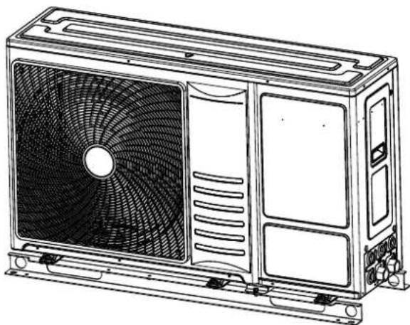
Line drawing of a front-end air conditioner unit with fan blades and cooling fins (no text or symbols)2251081
ORIGINAL INSTRUCTIONS

5410
Declaration of Conformity (Manufacturer's Declaration)
F
01 * and judged positively by:
01 * Manufacturing number and manufacturing year: refer to model Nameplate.
Note: This declaration becomes invalid, if technical or operational modifications are introduced without the manufacturer's consent.
01 is authorised to Compile the Technical Construction File.
Position/Title: Director
Date: October 25, 2021
English
Specifications in this manual are subject to change without notice in order that Hisense may bring the latest innovations to their customers.
The English version is the original one; other languages are translated from English. Should any discrepancy occur between the English and the translated versions, the English version shall prevail.
Français
This product shall not be mixed with general house waste at the end of its life and it shall be retired according to the appropriated local or national regulations in an environmentally correct way. Due to the refrigerant, oil and other components contained in heat pump, its dismantling must be done by a professional installer according to the applicable regulations. Contact to the corresponding authorities for more information.

ADVERTISSEMENT
Following Regulation EU No. 517/2014 on Certain Fluorinated Greenhouse gases, it is mandatory to fill in the label attached to the unit with the total amount of refrigerant charged on the installation. Do not vent R32 into the atmosphere: R32 are fluorinated greenhouse gases covered by the Kyoto protocol global warming potential (GWP)R32 = 675. Tn of CO₂ equivalent of fluorinated greenhouse gases contained is calculated by indicated GWP * Total Charge (in kg)indicated in the product label and divided by 1000.
Français
English (Only when using R32)

WARNING
BURST HAZARD
Do not allow air or any gas mixture containing oxygen into refrigerant cycle (i.e. piping)
RISK OF EXPLOSION
The compressor must be stopped before removing the refrigerant pipes.
All service valves must be fully closed after pumping down operation.

WARNING
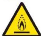
This symbol displayed on the unit indicates that this appliance is filled with R32, an odourless flammable refrigerant gas with low burning velocity (A2L class pursuant to ISO 817). If the refrigerant is leaked, there is a possibility of ignition if it enters in contact with an external ignition source.

CAUTION
This symbol displayed on the unit indicates that this appliance shall be handled by authorized service personnel only, referring to the Installation Manual.

CAUTION
This symbol displayed on the unit indicates that there is relevant information included in the Operation Manual and/or Installation Manual.
1.1 GENERAL NOTES....1
1.2 GENERAL SAFETY....1
- SAFETY 4
2.1 APPLIED SYMBOLS....4
2.2 ADDITIONAL INFORMATION ABOUT SAFETY 4
- IMPORTANT NOTICE 5
3.1 INFORMATION......5
3.2 MINIMUM FLOOR AREA REQUIREMENTS 6
3.3 CAUTION OF THE PRESSURE BYCHECK JOINT....7
- TRANSPORTATION AND HANDLING....7
4.1 TRANSPORTATION 7
4.2 HANDLING 7
- BEFORE OPERATION 8
- GENERAL DIMENSIONS 8
- UNIT INSTALLATION 9
7.1 INSTALLATION SPACE 9
7.2 INSTALLATION PLACE PROVISION 11
7.3 DRAIN PIPING....11
7.4 WATER PIPING 12
- REFRIGERANT CIRCUIT....13
8.1 REFRIGERANT CHARGE 13
8.2 PRECAUTIONS IN THE EVENT OFREFRIGERANT LEAKS.... 13
- This manual gives a common description and information for this heat pump air conditioner which you operate as well for other models.
- This manual should be considered as a permanent part of the heat pump air conditioning equipment and should remain with the air conditioning equipment.
- No part of this publication may be reproduced, copied, filed or transmitted in any shape or form without the permission of Hisense.
- Within the policy of continuous improvement of its products, Hisense reserves the right to make changes at any time without prior notification and without being compelled to introducing them into products previously sold. This document may therefore have been subject to amendments during the life of the product.
- As a result, some of the images or data used to illustrate this document may not refer to specific models. No claims will be accepted based on the data, illustrations and descriptions included in this manual.
- This heat pump air conditioner has been designed for the following ambient temperatures. Please operate the air conditioner within the ranges.
Temperature
| Min. Max. | |||
| Outdoor ambient | Space heating -25°C DB 35°C DB | ||
| Domestic hot water (DHW) -25°C DB 40°C DB | |||
| Space cooling | 5°C DB | 46°C DB | |
| Water outlet | Space heating 15°C 60°C | ||
| Space cooling 5°C 22°C | |||
| Domestic hot water (DHW) 30°C 55°C (75°C*) | |||
| Water pressure | 1 bar | 3 bar | |
DB: Dry Bulb
*: When there is an electric heater mounted in the DHW tank, the setting temperature can reach 75 °C.
- Upon receiving this product, inspect it for any shipping damage. Claims for damage, either apparent or concealed, in a written form, should be filed immediately with the shipping company.
- Check the model number, electrical characteristics (power supply, voltage and frequency) and accessories to determine if they are correct.
- The standard utilization of the unit shall be explained in these instructions. Therefore, the utilization of the unit other than those indicated in these instructions is not recommended. Please contact your local agent, as the occasion arises.
- If you have any questions, please contact your dealer or designated service center of Hisense.
1.2 GENERAL SAFETY
- Notice: Servicing shall be performed only as recommended by the manufacturer.
• Qualification of workers
Warning: Every working procedure that affects safety means shall only be carried out by competent persons.
Examples for such working procedures are:
- breaking into the refrigerating circuit.
- opening of sealed components.
- opening of ventilated enclosures.
• Information on servicing
- Prior to beginning work on systems, safety checks are necessary to ensure that the risk of ignition is minimized. - Work shall be undertaken under a controlled procedure so as to minimized the risk of flammable gas or vapor being present while the work is being performed.
- Work in confined spaces shall be avoided. The area around the workspace shall be sectioned off. Ensure that the conditions within the area have been made safe by control of flammable material.
• Checking for presence of refrigerant
- The area shall be checked with an appropriate refrigerant detector prior to and during work. The leak detection equipment should be suitable for use with all applicable refrigerants, i.e. non-sparking, adequately sealed or intrinsically safe.
• Presence of fire extinguisher
- If any hot work is to be conducted, appropriate fire extinguishing equipment shall be available to hand. Have a dry powder or CO_2 fire extinguisher adjacent to the charging area.
- No ignition sources
- All possible ignition sources, including cigarette smoking, should be kept sufficiently far away from the site of installation, repairing, removing and disposal. Prior to work taking place, the area around the equipment is to be surveyed to make sure that there are no flammable hazards or ignition risks. "No Smoking" signs shall be displayed.
• Ventilated area
- Ensure that the area is in the open or that it is adequately ventilated before breaking into the system or conducting any hot work. A degree of ventilation shall continue during the period that the work is carried out. The ventilation should safely disperse any released refrigerant and preferably expel it externally into the atmosphere.
• Checks to the refrigeration equipment
- where electrical components are being changed, they shall be fit for the purpose and to the correct specification. At all times the manufacturer's maintenance and service guidelines shall be followed. If in doubt, consult the manufacturer's technical department for assistance. The following checks shall be applied to installations
- The charge size is in accordance with the room size within which the refrigerant containing parts are installed.
- The ventilation machinery and outlets are operating adequately and are not obstructed.
- If an indirect refrigerating circuit is being used, the secondary circuit shall be checked for the presence of refrigerant.
- Marking to the equipment continues to be visible and legible. Markings and signs that are illegible shall be corrected.
- Refrigeration pipe or components are installed in a position where they are unlikely to be exposed to any substance which may corrode refrigerant containing components, unless the components are constructed of materials which are inherently resistant to being corroded or are suitably protected against being so corroded.
• Checks to electrical devices
- Repair and maintenance to electrical components shall include initial safety checks and component inspection procedures. If a fault exists that could compromise safety, then no electrical supply shall be connected to the circuit until it is satisfactorily dealt with. If the fault cannot be corrected immediately but it is necessary to continue operation, an adequate temporary solution shall be used. This shall be reported to the owner of the equipment, so that all parties are advised.
- Initial safety checks shall include:
(1) that capacitors are discharged: this shall be done in a safe manner to avoid possibility of sparking;
(2) that no live electrical components and wiring are exposed while charging, recovering or purging the system;
(3) that there is continuity of earth bonding.
• Repairs to sealed components
- During repairs to sealed components, all electrical supplies shall be disconnected prior to any removal of sealed covers, etc. If it is absolutely necessary to have an electrical supply to equipment during servicing, then a permanently operating form of leak detection shall be located at the most critical point to warn of a potentially hazardous situation.
- Ensure that by working on electrical components, the casing is not altered in such a way that the level of protection is affected, including damage to cables, excessive number of connections, terminals not made to original specification, damage to seals, incorrect fitting of glands, etc.
- Ensure that the apparatus is mounted securely.
- Ensure that seals or sealing materials have not degraded to the point that they no longer serve the purpose of preventing the ingress of flammable atmospheres. Replacement parts shall be in accordance with the manufacturer's specifications.
• Repair to intrinsically safe components
- Do not apply any permanent inductive or capacitance loads to the circuit without ensuring that this will not exceed the permissible voltage and current permitted for the equipment in use.
- Intrinsically safe components are the only types that can be worked on while live in the presence of a flammable atmosphere.
- Replace components only with parts specified by the manufacturer. Other parts may result in the ignition of refrigerant in the atmosphere from a leak.
. Cabling
- Check that cabling will not be subject to wear, corrosion, excessive pressure, vibration, sharp edges or any other adverse environmental effects. The check shall also take into account the effects of aging or continual vibration from sources such as compressors or fans.
• Detection of flammable refrigerants
- Under no circumstances shall potential sources of ignition be used in the searching for or detection of refrigerant leaks. A halide torch (or any other detector using a naked flame) shall not be used.
- Leak detection methods
- Electronic leak detectors may be used to detect refrigerant leaks but the sensitivity may not be adequate, or may need re-calibration for the flammable refrigerants.
- Ensure that the detector is not a potential source of ignition and is suitable for the refrigerant used. Leak detection equipment shall be set at a percentage of the LFL of the refrigerant and shall be calibrated to the refrigerant employed, and the appropriate percentage of gas (25 % maximum) is confirmed.
- The use of detergents containing chlorine shall be avoided.
- If a leak is suspected, all naked flames shall be removed/extinguished.
- If a leakage of refrigerant is found which requires brazing, all of the refrigerant shall be recovered from the system, or isolated (by means of shut off valves) in a part of the system remote from the leak. Oxygen free nitrogen (OFN) shall then be purged through the system both before and during the brazing process.
• Removal and evacuation
- The refrigerant charge shall be recovered into the correct recovery cylinders and the system shall be "flushed" with OFN to render the unit safe. This process may need to be repeated several times.
- Compressed air or oxygen shall not be used for purging refrigerant systems.
- Flushing shall be achieved by breaking the vacuum in the system with OFN and continuing to fill until the working pressure is achieved, then venting to atmosphere, and finally pulling down to a vacuum. This process shall be repeated until no refrigerant is within the system. When the final OFN charge is used, the system shall be vented down to atmospheric pressure to enable work to take place. This operation is absolutely vital if brazing operations on the pipework are to take place.
- The outlet for the vacuum pump is not close to any ignition sources and that ventilation is available.
- Charging procedures
- Ensure that contamination of different refrigerants does not occur when using charging equipment. Hoses or lines shall be as short as possible to minimise the amount of refrigerant contained in them.
- Cylinders shall be kept upright.
- Ensure that the refrigeration system is earthed prior to charging the system with refrigerant.
- Label the system when charging is complete (if not already).
- Extreme care shall be taken not to overfill the refrigeration system.
- Prior to recharging the system, it shall be pressure-tested with the appropriate purging gas. The system shall be leak-tested on completion of charging but prior to commissioning. A follow up leak test shall be carried out prior to leaving the site.
- Decommissioning
- Before carrying out this procedure, it is essential that the technician is completely familiar with the equipment and all its detail.
- Prior to the task being carried out, an oil and refrigerant sample shall be taken in case analysis is required prior to re-use of reclaimed refrigerant.
- Electrical power must be available before the task is commenced.
- Become familiar with the equipment and its operation.
- Isolate system electrically.
- Before attempting the procedure, ensure that:
(1) mechanical handling equipment is available, if required, for handling refrigerant cylinders;
(2) all personal protective equipment is available and being used correctly;
(3) the recovery process is supervised at all times by a competent person;
(4) recovery equipment and cylinders conform to the appropriate standards.
- Pump down refrigerant system, if possible.
- If a vacuum is not possible, make a manifold so that refrigerant can be removed from various parts of the system.
- Make sure that cylinder is situated on the scales before recovery takes place.
- Start the recovery machine and operate in accordance with manufacturer's instructions.
- Do not overfill cylinders. (No more than 80 % volume liquid charge).
- Do not exceed the maximum working pressure of the cylinder, even temporarily.
- When the cylinders have been filled correctly and the process completed, make sure that the cylinders and the equipment are removed from site promptly and all isolation valves on the equipment are closed off.
- Recovered refrigerant shall not be charged into another refrigeration system unless it has been cleaned and checked.
- Labelling
- Equipment shall be labelled stating that it has been decommissioned and emptied of refrigerant. The label shall be dated and signed.
- Ensure that there are labels on the equipment stating the equipment contains flammable refrigerant.
- Recovery
- When transferring refrigerant into cylinders, ensure that only appropriate refrigerant recovery cylinders are employed.
- Ensure that the correct number of cylinders for holding the total system charge are available. All cylinders to be used are designated for the recovered refrigerant and labelled for that refrigerant (i.e. special cylinders for the recovery of refrigerant).
- Cylinders shall be complete with pressure-relief valve and associated shut-off valves in good working order. Empty recovery cylinders are evacuated and, if possible, cooled before recovery occurs.
- The recovery equipment shall be in good working order with a set of instructions concerning the equipment that is at hand and shall be suitable for the recovery of all appropriate refrigerants.
- A set of calibrated weighing scales shall be available and in good working order. Hoses shall be complete with leak-free disconnect couplings and in good condition. Before using the recovery machine, check that it is in satisfactory working order, has been properly maintained and that any associated electrical components are sealed to prevent ignition in the event of a refrigerant release.
- The recovered refrigerant shall be returned to the refrigerant supplier in the correct recovery cylinder, and the relevant waste transfer note arranged.
- Do not mix refrigerants in recovery units and especially not in cylinders.
- If compressors or compressor oils are to be removed, ensure that they have been evacuated to an acceptable level to make certain that flammable refrigerant does not remain within the lubricant.
- The evacuation process shall be carried out prior to returning the compressor to the suppliers.
- Only electric heating to the compressor body shall be employed to accelerate this process.
- When oil is drained from a system, it shall be carried out safely.
2 SAFETY
2.1 APPLIED SYMBOLS
- During normal heat pump system design work or unit installation, greater attention must be paid in certain situations requiring particular care in order to avoid damage to the unit, the installation or the building or property.
- Situations that pose a risk to the safety of those in the surrounding area or to the unit itself are clearly indicated in this manual.
- Signal words (DANGER, CAUTION and NOTE) are used to identify levels of hazard seriousness. Pay close attention to these symbols and to the messages following them, as your safety and that of others depends on it.

DANGER
• The text following this symbol contains information and instructions relating directly to your safety.
• Not taking these instructions into account could lead to serious, very serious or even fatal injuries to you and others.

CAUTION
- The text following this symbol contains information and instructions relating directly to your safety.
• Not taking these instructions into account could lead to minor injuries to you and others. - Not taking these instructions into account could lead to unit damage.

NOTE
- The text following this symbol contains information and instructions that may be use or that require a more thorough explanation.
- Instructions regarding inspections to be made on unit parts or systems may also be included.

DANGER

This appliance is filled with R32, an odourless low burning velocity refrigerant. If the refrigerant is leaked, there is a possibility of ignition if it enters in contact with an external ignitions source.
RISK OF EXPLOSION
The compressor must be stopped before removing the refrigerant pipes. All service valves must be fully closed after pumping down operation.
| Symbol Explanation | |
| Before installation, read the installation and operation manual, and the wiring instruction sheet. | |
| Before performing maintenance and service tasks, read the service manual. | |
| For more information, see the Technical, Installation and Service Handbook. | |
2.2 ADDITIONAL INFORMATION ABOUT SAFETY

DANGER
- DO NOT CONNECT THE POWER SUPPLY TO THE UNIT PRIOR TO FILLING THE SPACE HEATING CIRCUIT (AND DHW CIRCUIT IF IT WERE THE CASE) WITH WATER AND CHECKING WATER PRESSURE AND THE TOTAL ABSENCE OF ANY WATER LEAKAGE.
- Do not pour water into the unit. These products are equipped with electrical parts. If the electrical components are in contact with water, a serious electrical shock will take place.
• Do not touch or adjust safety devices inside the unit. If these devices are touched or adjusted, a serious accident can take place. - Do not open the service cover or access inside the unit without disconnecting the main power supply.
- In case of fire, Turn OFF the main switch, put out the fire at once and contact your service contractor.
- Disconnect the appliance from its power source during service and when replacing parts.
- It must be ensured that the heat pump cannot operate accidentally without water neither with air inside hydraulic system.
- Check that the earth wire is securely connected. If the unit is not properly earthed, it may lead to electric shock.
- Do not connect the earth wire to gas piping, water piping, lighting conductor or earth wire of a telephone.
• Fix the cables securely. External forces on the terminals could lead to a fire. - Use an ELB (earth leakage breaker, with an actuation time of 0.1s or less). In the event of a fault, there is danger of an electric shock or a fire if it is not used.
• Do not charge oxygen, acetylene or other flammable and poisonous gases into the refrigerant cycle when performing a leakage test or an air-tightness test. These types of gases are extremely dangerous and can cause an explosion. - Do not install the unit in the following places, otherwise, it may lead to a fire, deformation, corrosion or failure.
- Places where oil (including machinery oil) splashes.
- Places where flammable gas may generate or flow.
- Places where there is splashing water.
- Places where sulfide gas drifts such as in hot spring.
- Places where strong wind with high salinity blows such as coast regions, or places with an atmosphere of acidity or alkalinity.
- Do not install the unit in the place where silicon gas drifts. If the silicon gas attaches to the surface of heat exchanger, the fin surface repels water. As a result, drain water splashes outside of the drain pan and splashed water runs inside of electrical box. In the end, water leakage or electrical devices failure may occur.
- Means for disconnection from the supply mains, which have a contact separation in all poles that provide full disconnection under overvoltage category III conditions, must be incorporated in the fixed wiring in accordance with the wiring rules.
- The appliance shall be installed in accordance with national wiring regulations.
- The installation and service of this product shall be carried out by professional personnel, who have been trained and certified by national training organizations that are accredited to teach the relevant national competency standards that may be set in legislation.

CAUTION
- Do not use any sprays such as insecticide, lacquer, hair spray or other flammable gases within approximately 1 meter from the system.
- If circuit breaker or fuse is often activated, stop the system and contact your service contractor.
- Do not put any foreign material (sticks, etc...) inside the units. These units have high speed rotating fans and it is dangerous when any object touches them.
- Do not let any foreign body into the water inlet and outlet unit.
• Refrigerant leakage can cause difficulty with breathing due to insufficient air. - Installation and service engineering must comply with local standards, laws and regulations. The standards (British Standard, BS4434) may be applicable if local regulations are not available.
- This air to water heat pump has been designed for standard water heating for human beings only. Do not use this for other functions that are not included in the controller.
- Do not install the unit in the place where the breeze directly catches the animals and plants. It could adversely affect the animals and plants.
- Pay attention to the following points when the unit is installed in hospital or other facilities where there are strong electromagnetic waves from medical equipment.
- Do not install the unit where the electromagnetic wave is directly radiated to the electrical box, wiring, controller and adapter.
- At least 3 meters from strong electromagnetic wave radiators, such as radio equipment.
• If the supply cord is damaged, it must be replaced by the manufacturer, its service agent or similarly qualified persons in order to avoid a hazard.
- Without reading the installation manual, do not carry out water piping connection and wiring connection.
- Check whether the earth wire connection is correct and firm.
- Connect to the fuse of specified capacity.
- The appliance is not to be used by children or person with reduced physical, sensory or mental capabilities, or lack of experience and knowledge, unless they have been given supervision or instruction concerning use of the appliance by a person responsible for their safety.
- This appliance can be used by children aged from 8 years and above and persons with reduced physical, sensory or mental capabilities or lack of experience and knowledge if they have been given supervision or instruction concerning use of the appliance in a safe way and understand the hazards involved. Children shall not play with the appliance. Cleaning and user maintenance shall not be made by children without supervision.

NOTE
It is recommended to ventilate the room every 3 or 4 hours.
The air conditioner may not work properly in the following cases.
- The power supplied by the power transformer is less than or equal to the electric power of the air conditioner.
- The large power-consuming equipment is too close to the power supply wiring of the air conditioner, large surge voltage may be inducted in the power supply wiring of the air conditioner.
3 IMPORTANT NOTICE
3.1 INFORMATION
- PLEASE READ THE MANUAL CAREFULLY BEFORE STARTING WORK ON THE INSTALLATION OF THE SYSTEM. Failure to observe the instructions for installation, use and operation described in this documentation may result in operating failure including potentially serious faults, or even the destruction of the system.
- Verify, in accordance with the manuals which appear in the unit, that all the information required for the correct installation of the system is included. If this is not the case, contact your distributor.
- HISENSE cannot anticipate every possible circumstance that might involve a potential hazard.
- The operation modes of these units are controlled by the master controller.
- This unit has not been designed for industrial processes, and is used as heat pump limited to the scope of the controller. For use in other applications, please contact your HISENSE dealer or service contractor.
- Keep the water temperature of the system above the freezing temperature.
- Check and make sure that the explanations of each part of this manual correspond to your air to water heat pump model.
• Refer to the models codification to confirm the main characteristics of your system.

DANGER
Pressure Vessel and Safety Device: This heat pump is equipped with a high pressure vessel under PED (Pressure Equipment Directive). The pressure vessel has been designed and tested before shipment according to PED. Also, in order to prevent the system from an abnormal pressure, a high pressure switch, which needs no field adjustment, is utilized in the refrigeration system. Therefore, this heat pump is protected from abnormal pressures. However, if abnormally high pressure is applied to the refrigeration cycle including the high pressure vessel(s), it will result in serious injury or death due to explosion of the pressure vessel. Do not apply a pressure higher than the following pressure to the system, by modifying or changing the high pressure switch.

DANGER
Do not use means to accelerate the defrosting process or to clean, other than those recommended by the manufacturer.
- The appliance shall be stored in a room without continuously operating ignition sources (for example: open flames, an operating gas appliance or an operating electric heater.
• Do not pierce or burn. - Be aware that the R32 refrigerants does not contain an odour.
Start-up and Operation: Check to ensure that all the stop valves are fully opened and no obstacle exists at the inlet/outlet sides before start-up and during the operation.
Maintenance: Periodically check the high pressure side pressure. If the pressure is higher than the maximum allowable pressure, stop the system and clean the heat exchanger or remove the cause.
Maximum allowable pressure : refer to nameplate.
3.2 MINIMUM FLOOR AREA REQUIREMENTS
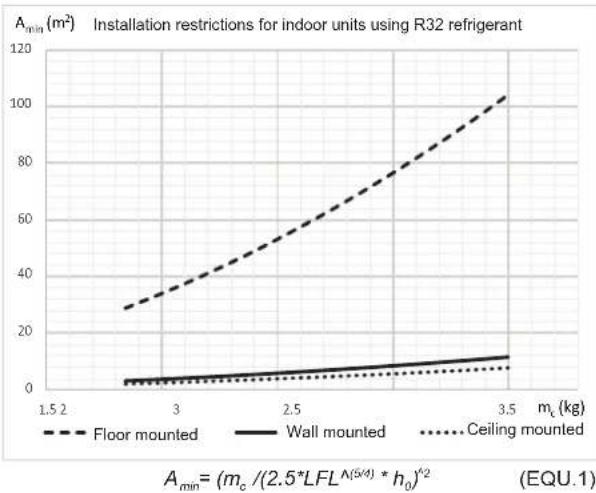
- The following chart and table shows the minimum floor area ( A_min ) required for the installation of an indoor unit from a refrigerant system containing a certain refrigerant charge ( m_c ) of R32 (A2L refrigerant), and supposing a total room height not lower than 2.2 m. (According to IEC 60335-2-40:2018 and EN 378-1:2016).
- For m_c < 1.84 kg, IEC 60335-2-40:2018 and EN 378-1:2016 do not establish any minimum floor area restriction. In that case check local regulations to ensure that no hard restrictions may apply.
line
| m_c (kg) | Floor mounted (m²) | Wall mounted (m²) | Ceiling mounted (m²) | | -------- | ------------------- | ------------------ | --------------------- | | 1.5 | 28 | 2 | 1 | | 3 | 40 | 3 | 2 | | 2.5 | 60 | 5 | 3 | | 3.5 | 100 | 10 | 5 |- A_ : Minimum installation area of an Indoor unit for a given refrigerant charge m_c (kg) and considering the installation height h_0 ( m^2 )
- h_0 : Installation height of the bottom side of the indoor unit + distance from the indoor unit bottom side to the lowest part for which a refrigerant leak may release to the indoor area.
- m_c : total system refrigerant charge that could be released to the indoor area in case of undetected refrigerant leak.
• LFL: Lower Flammability Limit for R32, 0.307 kg/m ^3 as established by EN 378-1:2016 and ISO 817. -
The A_ in the table above is calculated according to the formula (EQU.1) under the following conditions:
-
Floor mounted: h_0 = 0.6 m
- Wall mounted: h_0 = 1.8 m
- Ceiling mounted: h0 = 2.2 m
- For safety, the A min must be calculated according to the actual installation by professionals.
| Minimum floor area for equipment installed inside | |||
| m_c( kg) | A_ ( m^2) | A_ ( m^2) | A_ ( m^2) |
| Floor mounted | Wall mounted | Ceiling mounted | |
| 1.84 | 28.81 | 3.20 | 2.14 |
| 1.9 | 30.72 | 3.41 | 2.29 |
| 2.0 | 34.04 | 3.78 | 2.53 |
| 2.1 | 37.53 | 4.17 | 2.79 |
| 2.2 | 41.19 | 4.58 | 3.06 |
| 2.3 | 45.02 | 5.00 | 3.35 |
| 2.4 | 49.02 | 5.45 | 3.65 |
| 2.5 | 53.19 | 5.91 | 3.96 |
| 2.6 | 57.53 | 6.39 | 4.28 |
| 2.7 | 62.04 | 6.89 | 4.61 |
| 2.8 | 66.72 | 7.41 | 4.96 |
| 2.9 | 71.58 | 7.95 | 5.32 |
| 3.0 | 76.6 | 8.51 | 5.70 |
| 3.1 | 81.79 | 9.09 | 6.08 |
| 3.2 | 87.15 | 9.68 | 6.48 |
| 3.3 | 92.68 | 10.30 | 6.89 |
| 3.4 | 98.39 | 10.93 | 7.32 |
| 3.5 | 104.26 | 11.58 | 7.75 |
CAUTION
- Do not charge OXYGEN, ACETYLENE, or other flammable and poisonous gases into the refrigerant because an explosion can occur. It is recommended that oxygen free nitrogen be charged for these types of tests cycle when performing a leakage test or an air-tightness test. These types of gases are extremely dangerous.
- Check for refrigerant leakage in detail. If a large refrigerant leakage occurred, it would cause difficulty with breathing or harmful gases would occur if a fire were being used in the room.
i NOTE
- Fill in the label attached to the unit with the amount of refrigerant charged and Tonnes of CO_2 equivalent of fluorinated greenhouse gases contained on the installation.
NOTE
● This equipment Contains fluorinated greenhouse gases.
● Refrigerant: R32, global warming potential (GWP) value :675.
● Weight (kg) of Refrigerant charged before shipment: Reference to the nameplate ____ ① kg.
● Weight (kg) of Refrigerant charged additionally on site: Reference to the manual ② kg.
● Weight (kg) of Refrigerant charged totally:
③=(①+②), ____ kg.
- Tonnes of CO2 equivalent of fluorinated greenhouse gases contained:③×675/1000, tCO 2 eq.
! DANGER
- Only use R32 as refrigerant. Other substances may cause explosions and accidents.
- R32 is fluorinated greenhouse gases. Its global warming potential (GWP) value is 675. Do NOT vent these gases into the atmosphere.
- Tonnes of CO_2 equivalent of fluorinated greenhouse gases contained is calculated by GWP value of the refrigerant × Total refrigerant charge [kg] / 1000 in the label.
• Mass of charged refrigerant: refer to chapter 8.1.
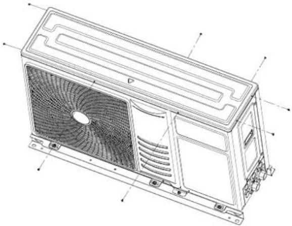
3.3 CAUTION OF THE PRESSURE BY CHECK JOINT
When the pressure is measured, use the check joint inside the unit, as shown below.
Step1: Remove the screws (8 pc) around the top cover.
natural_image
Technical line drawing of a computer HVAC unit with fan and ventilation slots (no text or labels)Step2: Remove the top cover.
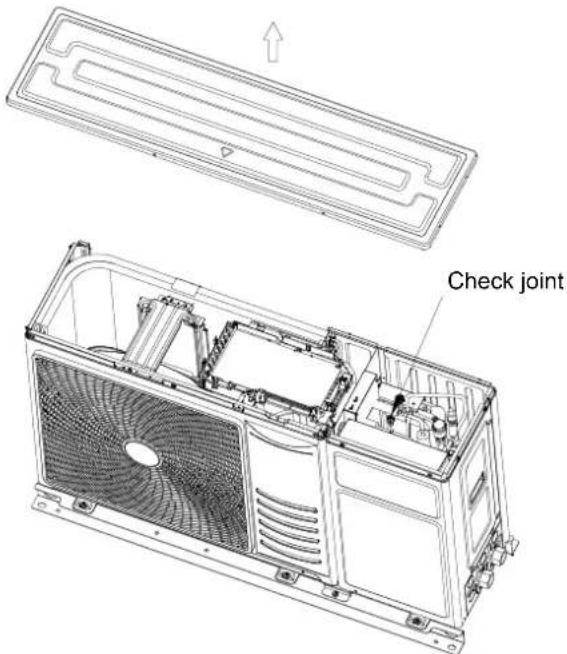
Step3: Connect the pressure gauge to the check joint according to the following table because of high pressure side and low pressure side changes by operation mode.
Check joint:
| Cooling operation | Heating operation |
| Low pressure | High pressure |

NOTE
Be careful that refrigerant and oil do not splash to the electrical parts at removing the charge hoses.
4 TRANSPORTATION AND HANDLING
4.1 TRANSPORTATION
Transport the product as close to the installation location as possible before unpacking.

CAUTION
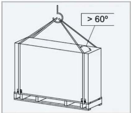
- Do not step on or put any materials on the product.
• Apply two lifting wires onto the unit when lifting it by crane.
4.2 HANDLING

CAUTION
- Do not step on or put any materials on the product.
- Do not put any foreign material into the unit and check to ensure that none exists in the unit before the installation and test run. Otherwise, a fire or failure, etc. may occur.
- When hanging the unit, ensure a balance of the unit, check safety and lift it up smoothly.
- Do not remove any packing materials.
- Hang the unit under packing condition with two ropes.
- For safety reasons ensure that the unit is lifted smoothly and does not lean.
• Two or more personnel should be used to move the unit.
5 BEFORE OPERATION

CAUTION
- When the system is started after a shut-off longer that approximately 3 months, it is recommended to check the system by your service contractor.
- Turn OFF the main switch when the system is to be stopped for a long period of time: If the main switch is not turned OFF, electricity will be used, because the oil heater is always energised during compressor stopping.
- Make sure that the unit is not covered with snow or ice. If covered, remove it by using hot water (approximately 50°C). If the water temperature is higher than 50°C, it will cause damage to plastic parts.

NOTE
• The accessories shown in the table are supplied inside the unit.
• If any of these accessories are not packed with the unit or any damage to the unit is detected, please contact your dealer.
| Accessory | Image | Qty. | Remarks |
| Instruction manual |  | 1 | Basic instructions for the installation of the device. |
| Rubber ring |  | 4 | For electrical wiring connection. |
| Shut-off valve (G1") | 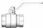 | 1 | Connect at the water outlet, for connecting/ disconnecting water pipe. |
| Shut-off valve with filter (G1") |  | 1 | Connect at the water inlet, for connecting/ disconnecting water pipe, and filtering impurities in water. |
| Drain nozzle | [YXY] | 2 | For water discharge when necessary. |
| Gasket |  | 6 | Six gaskets for each connections between the unit and shut-off valves (inlet/outlet) |
| Controller |  | 1 | Used for device operation. |
6 GENERAL DIMENSIONS
(Units: mm)
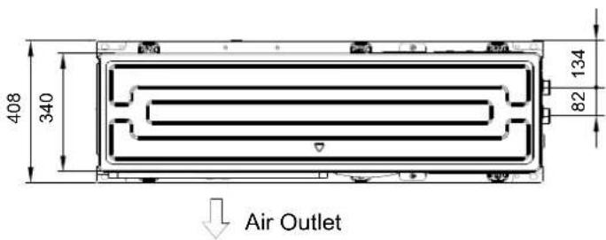
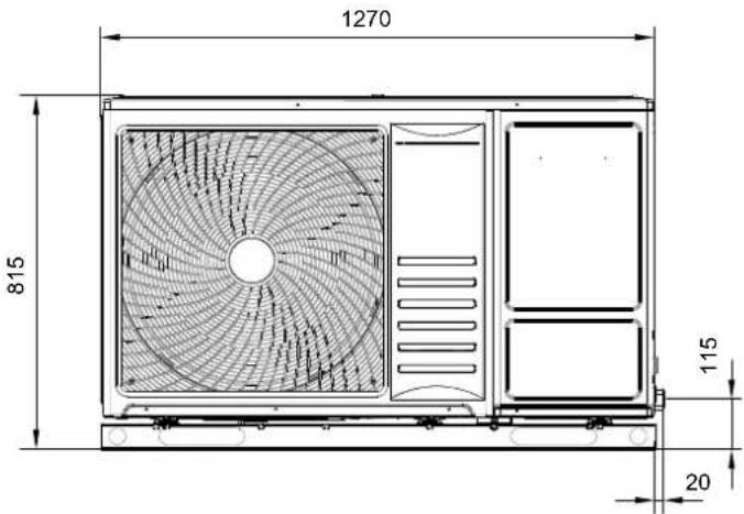
natural_image
Technical line drawing of a vertical electronic device with internal components and a 68mm dimension label (no text or symbols beyond the dimension)7 UNIT INSTALLATION

CAUTION
- Transport the products as close to the installation location as possible before unpacking.
• Do not put any material on the products. - When installing more than one units together, keep clearance between the units of more than 500 mm, and avoid obstacles that should hamper air intake.
• Install the unit in the shade or not exposed to direct sunshine or direct radiation from high temperature heat source.
• Make sure that the foundation is flat and sufficiently strong. - This unit has aluminum fin with sharp edges. Pay attention to the fin to avoid injury. Install the unit in a restricted area not accessible by the general public
- When installing the unit in snow-covered areas, mount the field-supplied hoods at the discharge side of the unit and the inlet side of the heat exchanger.
- Do not install the unit in a space where a seasonal wind directly blows to the heat exchanger or a wind from a building space directly blows to the fan.

DANGER
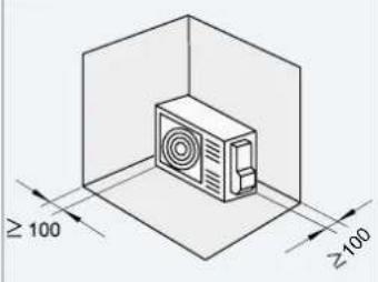
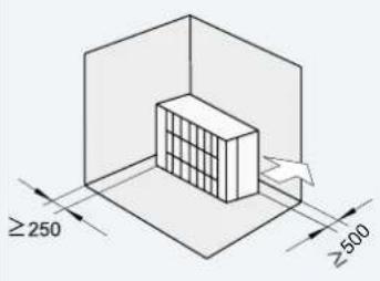
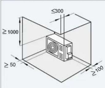
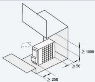
• Install the unit with sufficient clearance around it for operation and maintenance as shown in the next figures. Install the unit where good ventilation is available.
- Do not install the unit where there is a high level of oil mist, salty air or sulphurous atmosphere.
• Install the unit as far as possible (being at least 3 meters) from electromagnetic wave radiator (such as medical equipment).
- For cleaning, use noninflammable and nontoxic cleaning liquid. Use of inflammable agent should cause explosion or fire.
- Work with sufficient ventilation, for working in an enclosed space should cause oxygen deficiency. Toxic gas should be produced when cleaning agent is heated to high temperature by e.g., being exposed to fire.
• Install the unit in a location where noise emitted by the unit does not disturb neighbours.
- Cleaning liquid shall be collected after cleaning.
- Pay attention not to clamp cables when attaching the service cover to avoid electric shock or fire
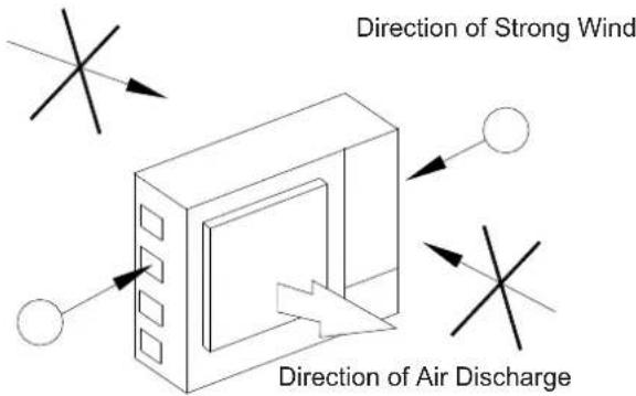
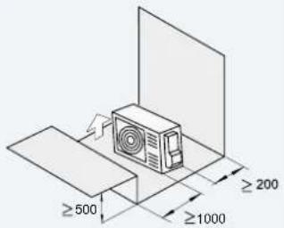
- In case of installation in the open spaces unavoidably where there is no buildings or surrounding structures, install near the wall to avoid facing the wind directly. Ensure that the service space should be secured.
A Wall to Guard Against Wind
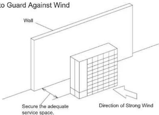
NOTE:
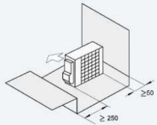
If the extreme strong wind blows directly against the air discharge portion, the fan may rotate reversely and be damaged.
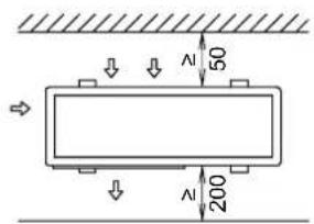
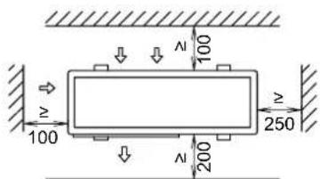
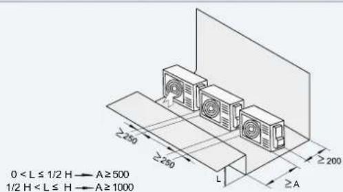
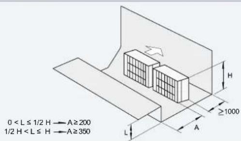
7.1 INSTALLATION SPACE
(Units: mm)
a) In case of front side and either of the sides are open (single unit)
b) In case that surrounding wall exist (single unit)
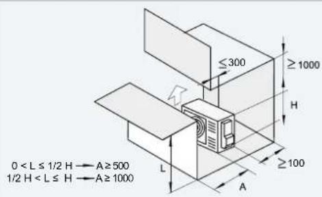
c) In case that upper side obstacles exist (single unit)
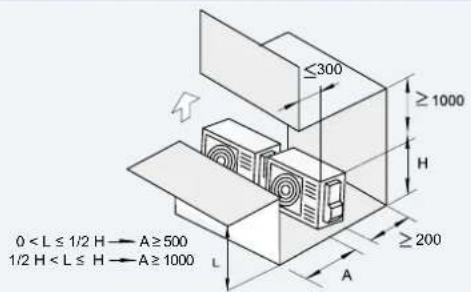
e) In case of front side and either of the sides are open (serial units)
d) In case that upper side obstacles exist (serial units)

f) In case that surrounding wall exist (serial units)
g) Horizontal (multiple units) h) Vertical (multiple units)
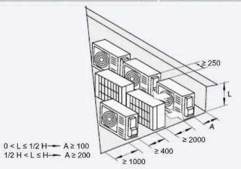
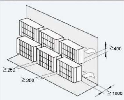
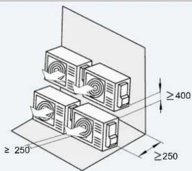
Do not stack more than two units in height. - Close gap (*) to avoid recirculating discharge air flow.

NOTE
• If L is greater than H, install the outdoor unit on the foundation, so that H is greater than or equal to L.
H: Outdoor unit height + foundation height
• Do not stack more than two units in height.
• In all cases, short circuit of air flow is not allowed.
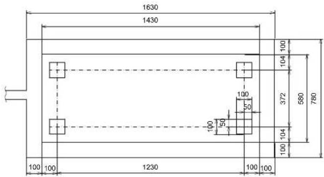
7.2 INSTALLATION PLACE PROVISION
◆ Concrete foundation
- Foundation shall be on a level surface and it is recommended to be 100-300 mm higher than ground level.
- Use M12 anchor bolts to fix the unit to the foundation (Foundation bolts, nuts and washers are not included, and must be field supplied)
- Drain water might turn into ice on cold weather areas. Therefore, when installing the unit on a roof or a veranda, avoid the draining on a public area since it may become slippery.
(Units: mm)

- The unit is low-vibration model, but consider using some floor reinforcement or anti-vibration mat/rubber when vibration should occur due to weakness of attached surface.
- The foundation shall be unified with the floor slab in order to ensure strength against a fall or for when the unit has to be moved.
- Drain water and rainwater are discharged from the bottom of the unit when in operation as well as when stopped.
- Choose a location with good drainage or place a water drain as shown in the drawing.
- Make the foundation flat and waterproof, as a water leakage may appear in case of, for instance, rain.
CAUTION
Pay attention to the following for installation:
- Installation shall ensure that unit will not incline, vibrate, make noise or fall down by a blast of wind or in an earthquake. Calculate quakeresistance strength to ensure that installation is strong enough against falling. Fix the unit with wires (field-supplied) when installing in a location without walls or windbreak and likely exposed to a blast of wind.
• Apply vibration-proof material where necessary.
7.3 DRAIN PIPING
When the base of the unit is temporarily utilized as a drain receiver and the drain water in it is discharged, two drain nozzles are needed to install on the bottom of the machine refer to the figure below. If necessary, link a separate drain pipe for each drain nozzle.
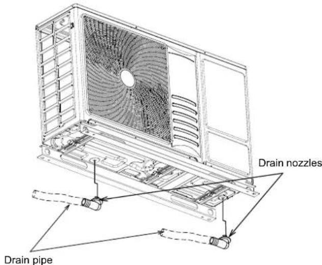
i NOTE
• The drain nozzles are factory-supplied.
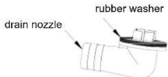
• The drain pipes (inner diameter:15mm) should be field-supplied.
- Do not use this drain nozzle set in a cold area, because the drain water may freeze.
- This drain boss is not sufficient to collect all the drain water. If collecting drain water is completely required, provide a drain-panel that is bigger than the unit base and install it under the unit with drainage.
7.4 WATER PIPING
7.4.1 GENERAL NOTES BEFORE PERFORMING PIPING WORK
- It is advisable to insulate the water pipes, joints and connections in order to avoid heat loss and dew condensation on the surface of the pipes or accidental injuries due to excessive heat on piping surfaces.
- It is recommended to use flexible joints for the water piping inlet and outlet in order to avoid vibration transmission.
• Water circuit must be performed and inspected by a licensed technician and must comply with all relevant European and national regulations. - Proper water pipe inspection should be performed after piping work to assure there is no water leakage in the space heating circuit.
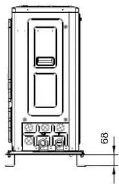
7.4.2 WATER PIPING CONNECTION
(1) Piping location and connection size
The unit is factory supplied with two unions to be connected to the water inlet/outlet pipe. Refer to the figure detailing the location of the water pipes location and connection sizes.
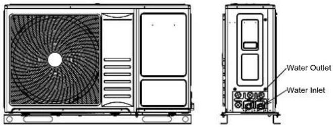
| Description Connection size | |
| Water Inlet | G1" (female) |
| Water Outlet | G1" (female) |
(2) Install shut-off valves
A shut-off valve and a shut-off valve with filter are provided with the unit. For convenience of repair and maintenance, install the shut-off valve with filter on water inlet pipe and the shut-off valve on water outlet pipe of the unit as follow.
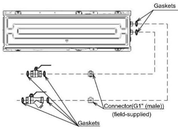

NOTE
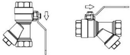
The shut-off valve with filter must be installed at water inlet of the unit, and water flow direction and installation direction must be confirmed as follow. The gasket in accessories can be installed at the two connections of shut-off valve and shut-off valve with filter.
natural_image
Technical line drawing of two mechanical valve assemblies with no visible text or symbols
CAUTION
- Rubber gasket must be mounted (accompanied with the unit), otherwise water leakage may be caused.
• Note the location of ball valve, and the direction of ball valve and drain valve, which are essential to maintenance. - Do NOT use excessive force when connecting the field piping and make sure the piping is aligned properly.
• Deformation of the piping can cause malfunctioning of the unit. - Screw up ball valves and other pipeline connections by using two wrenches.
(3) Additional water strainer

CAUTION
- Provide a 50 mesh or more water strainer at the water inlet side of water piping. Otherwise, damage to the plate heat exchanger may occur. In the plate heat exchanger, water flows through a narrow space between the plates. Therefore, there is a possibility that freezing or corrosion may occur if foreign particles or dust clog the flow of water between the plates.
• This is not required when cooling mode is not used.
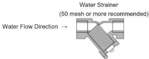
- The water piping connection needs to be completed after flushing the water system
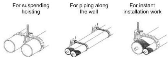
7.4.3 SUSPENSION OF WATER PIPING
Suspend the water piping at certain points and prevent the water piping from being in direct contact with the building: walls, ceilings, etc...
If there is direct contact between pipes, abnormal sound may occur due to the vibration of the piping. Pay special attention in cases of short piping lengths.
Do not fix the water pipes directly with the metal fittings (piping may expand and contract).
Some examples for suspension method are shown below.
8 REFRIGERANT CIRCUIT
8.1 REFRIGERANT CHARGE
This appliance is filled with R32, an odourless flammable refrigerant gas with low burning velocity (A2L class pursuant to ISO 817), and is factory charged in the unit.
Refrigerant charge before shipment ( W0 (kg) )
| Model | W0 (kg) |
| 044(2.0HP) | 1.17 |
| 080(3.0HP) | 1.21 |
8.2 PRECAUTIONS IN THE EVENT OF REFRIGERANT LEAKS
If the refrigerant is leaked, there is a possibility of ignition if it is in contact with an external ignition source.
Make sure that unit installation comply with applicable legislation in each country.
The installers and those responsible for drafting the specifications are obliged to comply with local safety codes and regulations in the case of refrigerant leakage.

CAUTION
- Do not charge OXYGEN, ACETYLENE, or other flammable and poisonous gases into the refrigerant because an explosion can occur. It is recommended that oxygen free nitrogen be charged for these types of tests cycle when performing a leakage test or an airtightness test. These types of gases are extremely dangerous.
• Insulate the unions and flare-nuts at the piping connection part completely
• Insulate the piping completely, if not, it will cause a decrease of performance or sweating on the surface of the pipe. - Charge refrigerant correctly. Overcharging or insufficient charging could cause a compressor failure.
- Check for refrigerant leakage in detail. If a large refrigerant leakage occurred, it would cause difficulty with breathing or harmful gases would occur if a fire was being used in the room.
Do not connect the power supply to the unit prior to filling the space heating circuit (and DHW circuit if it were the case) with water and checking water pressure and the total absence of any water leakage.
flowchart
graph TD
    A["Unit"] --> B["1"]
    B --> C["2"]
    C --> D["7"]
    D --> E["8"]
    E --> F["9a"]
    F --> G["9b"]
    G --> H["Radiator"]
    H --> I["Cooling fan coil"]
    I --> J["15"]
    J --> K["16"]
    K --> L["3WV"]
    L --> M["4"]
    M --> N["5"]
    N --> O["6"]
    O --> P["10"]
    P --> Q["17"]
    Q --> R["Floor heating"]
    R --> S["11"]
    S --> T["12"]
    T --> U["13"]
    U --> V["14"]
    V --> W["9cT"]
    W --> X["9b"]
    X --> Y["3WV"]
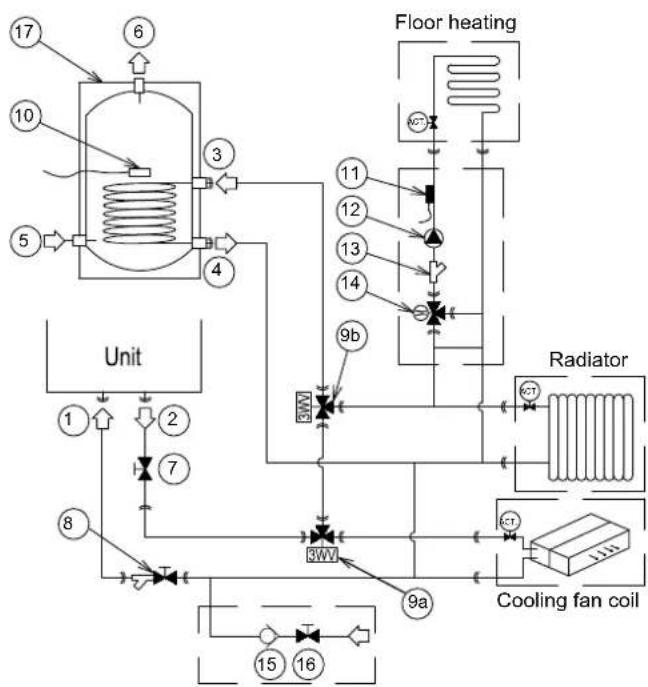
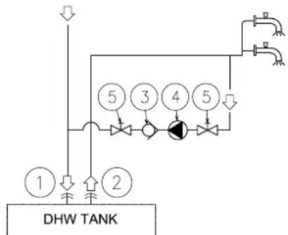
| Nature No. | Part name | |||
| Piping connections | 1 | Water inlet of the unit | ||
| 2 | Water outlet of the unit | |||
| 3 | DHW tank inner coil inlet | |||
| 4 | DHW tank inner coil outlet | |||
| 5 | Water inlet (DHW) | |||
| 6 | Water outlet (DHW) | |||
| Factory supplied | 7 | Shut-off valve | ||
| 8 | Shut-off valve with filter | |||
| Optional accessories | 9 | 3-way valve | 9a | 3WV Cooling |
| 9b | 3WV DHW | |||
| 10 | Thermistor ( for DHW) | |||
| 11 | Thermistor ( for Space heating) | |||
| Field supplied | 12 | Water pump | ||
| 13 | Filter | |||
| 14 | Mixing valve | |||
| 15 | Check valve | |||
| 16 | Shut-off valve | |||
| 17 | Domestic hot water tank | |||
As an installation example of space heating / cooling and Domestic hot water (DHW), the following hydraulic elements are necessary to correctly perform the space heating / cooling and DHW water circuit:
- The factory supplied shut-off valve (7) need to be installed at water outlet of the unit, and shut-off valve with filter (8) need to be installed horizontally at water inlet of the unit.
- A water check valve (15) with a shut-off valve (16) must be connected to the water filling point when filling the water circuit. The check valve acts as a safety device to protect the installation.
- A domestic hot water tank (17) has to be installed in combination with the space heating / cooling.
- 3-way valves (9) must be connected at one point of the water outlet pipe of the installation, used to divert the water circulation for specific functions. As shown in example, connect straight through of 3-way valve to DHW tank inner coil.
- DHW thermistor (10) must be installed to reach the inner wall of the DHW tank and keep in good contact with it. Space heating thermistor (10) must be installed on the metal tube close to space heating, and keep in good contact with it.
- Mixing valve (14) is recommended to use ESBE ARA661, which operation mode is 3-point SPDT. If mixing valve of other brands or models are used, the operation mode must be 3-point SPDT, and power supply must be 220-240V \~ 50Hz. The rotation time can be set in the master controller.
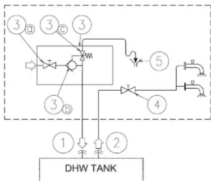
Additionally, the following elements are required for the DHW circuit:
flowchart
graph TD
    A["①"] --> B["②"]
    B --> C["③"]
    C --> D["④"]
    D --> E["⑤"]
    E --> F["⑥"]
    F --> G["⑦"]
    G --> H["⑧"]
    H --> I["⑨"]
    I --> J["⑩"]
    J --> K["⑪"]
    K --> L["⑫"]
    L --> M["⑬"]
    M --> N["⑭"]
    N --> O["⑮"]
    O --> P["⑯"]
    P --> Q["⑰"]
    Q --> R["⑱"]
    R --> S["⑲"]
    S --> T["⑳"]
    T --> U["㉑"]
    U --> V["㉒"]
    V --> W["㉓"]
    W --> X["㉔"]
    X --> Y["㉕"]
    Y --> Z["㉖"]
| Nature No. | Part name | ||
| Piping connections | 1 | Supplementary water inlet of DHW tank | |
| 2 | DHW tank outlet | ||
| Field supplied | 3 | Pressure and temperature relief valve | |
| 3a | Shut-off valve | ||
| 3b | Water check valve | ||
| 3c | Safety valve | ||
| 4 | Shut-off valve | ||
| 5 | Draining | ||
• A Shut-off valve (field supplied):
The shut-off valve (4) must be connected after the DHW tank outlet (2) in order to make easier any maintenance work.
• A Security water valve (Field-supplied):
This accessory (3) is a pressure and temperature relief valve that must be installed as near as possible to the Supplementary water inlet of DHW tank (1). It should ensure a correct draining (5) for the discharge valve of this valve. This security water valve should provide the following:
- Pressure protection
- Non-return function
- Shut-off valve
- Filling
- Draining

NOTE
The discharge pipe should always be open to the atmosphere, free of frost and in continuous slope to the down side in case that water leakage exists.
In case of a recirculation circuit for the DHW circuit, the following elements are required:
flowchart
graph TD
    A["1"] --> B["2"]
    B --> C["3"]
    C --> D["4"]
    D --> E["5"]
    E --> F["5"]
    F --> G["5"]
    G --> H["5"]
    H --> I["5"]
    I --> J["5"]
    J --> K["5"]
    K --> L["5"]
    L --> M["5"]
    M --> N["5"]
    N --> O["5"]
    O --> P["5"]
    P --> Q["5"]
    Q --> R["5"]
    R --> S["5"]
    S --> T["5"]
    T --> U["5"]
    U --> V["5"]
    V --> W["5"]
    W --> X["5"]
    X --> Y["5"]
    Y --> Z["5"]
    Z --> AA["5"]
    AA --> AB["5"]
    AB --> AC["5"]
    AC --> AD["5"]
    AD --> AE["5"]
    AE --> AF["5"]
    AF --> AG["5"]
    AG --> AH["5"]
    AH --> AI["5"]
    AI --> AJ["5"]
    AJ --> AK["5"]
    AK --> AL["5"]
    AL --> AM["5"]
    AM --> AN["5"]
    AN --> AO["5"]
    AO --> AP["5"]
    AP --> AQ["5"]
    AQ --> AR["5"]
    AR --> AS["5"]
    AS --> AT["5"]
    AT --> AU["5"]
    AU --> AV["5"]
    AV --> AW["5"]
    AW --> AX["5"]
    AX --> AY["5"]
| Nature No. | ||
| Piping connections | 1 | Supplementary water inlet of DHW tank |
| 2 | DHW tank outlet | |
| Field supplied | 3 | Water check valve |
| 4 | Water pump | |
| 5 | Shut-off valve |
- A Recirculation water pump (field supplied): This water pump (3) will help to correctly recirculate the hot water to the DHW inlet.
- A Water check valve (field supplied): This accessory (3) is connected after the recirculation water pump (4) in order to ensure the nonreturn of water.
- Two Shut-off valves (field supplied) (5): One before the recirculation water pump (4) and other after the water check valve accessory (3).

CAUTION
The water check valve shall be confirmed installed in the correct direction. Otherwise, serious damages may occur in the DHW tank.
9.2 REQUIREMENTS AND RECOMMENDATIONS FOR HYDRAULIC CIRCUIT
9.2.1 REQUIREMENTS FOR ANTI-FREEZING
- When the unit is stopped during shut-off periods and the ambient temperature is very low, the water inside the pipes and the circulating pump may freeze, thus damaging the pipes and the water pump. In these cases, the installer shall ensure that the water temperature inside the pipes does not fall below the freezing point. In order to prevent this, the unit has a self-protection mechanism which should be activated (refer to "10.6.1 DIP Switch Setting of PCB1").
- Even if the unit is stopped, the water pump may run under some circumstances, i.e., when the anti-freezing function is triggered.
- Keep the unit power on and water system unblocked to prevent water freezing, otherwise an alarm may occur.
- If the water system is blocked, an alarm of water flow will occur to stop the whole system.
- If machine is stopped for a long period of time in winter, drain out water in circuit and water pipes to prevent freezing.
- The anti-freezing protection is effective better with Auxiliary electric heater connected. It is advisable to install the Auxiliary electric heater for those models in which these are not supplied but optional.
• However, in case of a power failure or unit failure, these functions cannot guarantee protection.
Do one of the following to protect the water circuit against freezing:
- Add glycol to the water.
Glycol lowers the freezing point of the water.
- Install freeze protection valves.
Freeze protection valves drain the water from the system before it can freeze.
1 ) UHH] H□SURWHFWLRQ□E\ □J0\ FRO
About freeze protection by glycol
Adding glycol to the water lowers the freezing point of water.
![HISENSE AHZ-080HCDS1 - ) UHH] H□SURWHFWLRQ□E\ □J0\ FRO - 1](/content/2026/05/752007/images/6149a092a8e733665d95c63d7df15ed1c3259c11c3943677cd59a3106f0666fb.jpg)
CAUTION
• Ethylene glycol is toxic.
- Due to the presence of glycol, corrosion of the system is possible. Uninhibited glycol will turn acidic under the influence of oxygen. This process is accelerated by the presence of copper and high temperatures. The acidic uninhibited glycol attacks metal surfaces and forms galvanic corrosion cells that cause severe damage to the system. Therefore it is important that:
- The water treatment is correctly executed by a qualified water specialist.
- A glycol with corrosion inhibitors is selected to counteract acids formed by the oxidation of glycols,
- No automotive glycol is used because their corrosion inhibitors have a limited lifetime and contain silicates which can foul or plug the system.
- Galvanized pipes are NOT used in glycol systems since the presence may lead to the precipitation of certain components in the glycol's corrosion inhibitor.

NOTE
Glycol absorbs water from its environment. Therefore do NOT add glycol that has been exposed to air. Leaving the cap off the glycol container causes the concentration of water to increase. The glycol concentration is then lower than assumed. As a result, the hydraulic components might freeze up after all. Take preventive actions to ensure a minimal exposure of the glycol to air.
- Types of glycol
The types of glycol that can be used depend on whether the system contains a domestic hot water tank:
| If... Then... | |
| The system contains a domestic hot water tank | Only use propylene glycol ^(a) |
| The system does NOT contain a domestic hot water tank | You can use either propylene glycol ^(a) or ethylene glycol |
(a) Propylene glycol, including the necessary inhibitors, classified as Category III according to EN1717.
• Required concentration of glycol
The required concentration of glycol depends on the lowest expected outdoor temperature, and on whether you want to protect the system from bursting or from freezing. To prevent the system from freezing, more glycol is required.
Add glycol according to the table below.
| Lowest expected outdoor temperature | Prevent from bursting | Prevent from freezing |
| -5°C 10% 15% | ||
| -10°C 15% 25% | ||
| 15°C– 20% 35% | ||
| 20°C– 25% — | ||
| -25°C 30% — | ||
| 30°C– 35% — |
1) Protection against bursting: the glycol will prevent the piping from bursting, but NOT the liquid inside the piping from freezing.
2) Protection against freezing: the glycol will prevent the liquid inside the piping from freezing.

NOTE
- The required concentration might differ depending on the type of glycol. ALWAYS compare the requirements from the table above with the specifications provided by the glycol manufacturer. If necessary, meet the requirements set by the glycol manufacturer.
- The added concentration of glycol should NEVER exceed 35%. It is advisable to use a mixture with antifreeze glycol (ethylene or propylene at a concentration between 10% and 30%).
- If glycol is added to the water, do NOT install freeze protection valves. Possible consequence: Glycol leaking out of the freeze protection valves.
- If the concentration ratio of glycol can ensure the normal operation of the unit (the solution freezing temperature is lower than the ambient temperature -5°C), cancel Anti-freezing function(refer to "10.6.1 DIP Switch Setting of PCB1") to reduce the energy consumption.
- Unit performance may be reduced when operating with glycol, depending on the percentage of glycol used, since glycol is denser than water.
2 Freeze protection by freeze protection valves
About freeze protection valves
When no glycol is added to the water, you can use freeze protection valves to drain the water from the system before it can freeze.
- Install freeze protection valves (field supply) at all lowest points of the field piping.
- Normally closed valves (located indoors near the piping entry/exit points) can prevent that all water from indoor piping is drained when the freeze protection valves open.

NOTE
When freeze protection valves are installed, set the minimum cooling setpoint (default=7°C) at least 3°C higher than the maximum opening temperature of the freeze protection valve. If lower, freeze protection valves can open during cooling operation.
9.2.2 MINIMUM REQUIRED WATER VOLUME
The following part shows the minimum water volume in the system for product protection (anti-hunting) and temperature drop at defrosting.
- Minimum required water volume in each single water circuit of DHW / SWP for product protection (anti-hunting).
Water volume in each single water circuit of DHW / SWP need be greater than 20L. - Minimum required water volume in single water circuit of space cooling for product protection (anti-hunting).
The following table shows the minimum water volume needed in single water circuit of space cooling.
| Model 044(2.0HP) 080(3.0HP) | ||
| Minimum required water volume | 30L 45L | |
• Minimum required water volume during defrosting.
The following table shows the minimum water volume needed in single water circuit of space heating in case of safe defrosting.
| Lowest possible operation water temperature in single water circuit of space heating | 044(2.0HP) | 80(3.0HP) |
| ≥25°C | 61 L 61 L | |
| 20-25°C | 99 L 99 L | |
| 15-20°C | 158 L 158 | L |
| 10-15°C | 198 L 198 | L |

NOTE
- The values shown on the table are based on theoretical installation conditions. And the value can be different depending on each specific installation.
- To calculate minimum water volume the internal water volume of the unit is NOT included.
- Consult with local technical engineer under the special occasions where operation water temperature in single water circuit of space heating is lower than 20^ .
9.2.3 MINIMUM REQUIRED WATER FLOW
Check that the water pump of the water circuit works within the pump operating range and that the water flow is over the unit minimum value.
| Model | min. water flow(L/min) |
| 044(2.0HP) | 8.3 |
| 080(3.0HP) | 10.0 |
9.2.4 REQUIREMENTS AND RECOMMENDATIONS FOR HYDRAULIC CIRCUIT
- An additional special water filter is highly recommended to be installed on the space heating (field installation), in order to remove possible particles remaining from brazing which cannot be removed by the field supplied shut-off valve with filter.
- Put insulation on the pipes in order to avoid heat losses.
- Whenever possible, sluice valves should be installed for water piping, in order to minimize flow resistance and to maintain sufficient water flow.
- Ensure that the installation complies with applicable legislation in terms of piping connection and materials, hygienic measures, testing and the possible required use of some specific components like thermostatic mixing valves.
- The maximum water pressure is 3 bar (nominal opening pressure of the safety valve). Provide adequate reduction pressure device in the water circuit to ensure that the maximum pressure is NOT exceeded.
- The water pressure can be read on master controller, detected by the water pressure sensor located at inlet of plate heat exchanger. If water pressure exceeded 3 bar, the water pressure displayed on master controller would flash.
- Ensure that the drain pipes connected to the safety valve and to the air purge valve are properly driven to avoid water being in contact with unit components.
- Make sure that all field supplied components installed in the piping circuit can withstand the water pressure and the water temperature range in which the unit can operate. The units are conceived for exclusive use in a closed water circulation.
- The internal air pressure of the expansion vessel will be adapted to the water volume of the final installation (factory supplied with 1 bar of internal air pressure).
- Drain taps must be provided at all low points of the installation to permit complete drainage of the circuit during servicing.
- The maximum piping length depends on the maximum pressure availability in the water outlet pipe. Please check the pump curves.
- The unit is equipped with an air purge valve (factory supplied) at the highest location of the unit. If this location is not the highest of the water installation, air might be trapped inside the water pipes, which could cause system malfunction. In that case additional air purge valves (field supplied) should be installed to ensure no air enters the water circuit.
- For heating floor system, the air should be purged by mean of an external pump and an open circuit to avoid air bags.
9.3 WATER FILLING
1) Check that a water check valve (field supplied) with a shut-off valve (field supplied) is connected to the water filling point (water inlet connection) for filling the hydraulic circuit (see "9.1 Additional hydraulic necessary elements").
2) Make sure all the valves are open (water inlet/outlet shut-off valves and the rest of valves of the water circuit installation components).
3) Ensure that the air purge valve of the unit is open when installation (turn the screw cap of air purge valve twice at least).
4) Check that the drain pipes connected to the safety valve (keep the outlet of drain pipes located in the drain pan) are correctly connected to the general draining system. The safety valve is later used as an air purging device during the water filling procedure.
5) Fill the water circuit with water until the pressure displayed on the controller reaches 2.0 ± 0.2 bar. During all the operation conditions, the normal pressure range of water circuit is 1 \~ 2.5 bar.

NOTE
While the system is being filled with water, it is highly recommended to operate the safety valve manually so as to help with the air purging procedure.
6) Remove as much air from inside the water circuit as possible through the air purge valve and other air vents in the installation (fan coils, radiators...).
7) There are two methods to start the air purge procedure:
6) Remove as much air from inside the water circuit as possible through the air purge valve and other air vents in the installation (fan coils, radiators...). 7) There are two methods to start the air purge procedure:
a. Using the master controller to start air purge. (Refer to the master controller manual)
b. Using DSW4-1 of the PCB1: DSW4-1 ON: Start air purge DSW4-1 OFF: Stop air purge
8) If a little quantity of air is still remaining in the water circuit, it will be removed by the automatic air purge valve of the unit during the first hours of operation. Once the air in the installation has been removed, a reduction of water pressure in the circuit is very likely to occur. Therefore, additional water should be filled by booster pump until water pressure returns to approximate 2.0 bar.

NOTE
- The unit is equipped with an automatic air purge valve (factory supplied) at the highest location of the unit. Anyway, if there are higher points in the water installation, air might be trapped inside water pipes, which could cause system malfunction. In that case, additional air purge valves (field supplied) should be installed to ensure no air enters into the water circuit. The air purge valve should be located at points which are easily accessible for servicing.
- The water pressure indicated on the master controller may vary depending on the water temperature (the higher temperature, the higher pressure). Nevertheless, it must remain above 1 bar in order to prevent air from entering the circuit.
- Fill in the circuit with tap water. The water in the heating installation must comply with EN directive 98/83 EC. Non-sanitary controlled water is not recommended (for example, water from wells, rivers, lakes, etc.).
- The maximum water pressure is 3 bar (nominal opening pressure of the safety valve). Provide adequate reduction pressure device in the water circuit to ensure that the maximum pressure is NOT exceeded.
- For heating floor system, air should be purged by means of an external pump and an open circuit to prevent the formation of air pockets.
- Check carefully for leaks in the water circuit, connections and circuit elements.
- During water filling, it is necessary to ensure that water enters the unit from the water inlet to ensure that all water passes through the shut-off valve with filter to filter impurities, otherwise it may block the components inside the unit.
bar
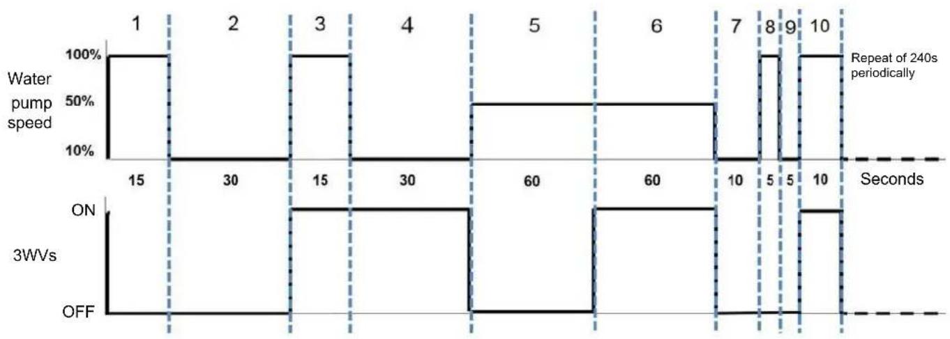
| Time (s) | Water pump speed (%) | 3WVs | OFF | |---|---|---|---| | 1 | 100 | ON | | | 2 | 100 | ON | | | 3 | 100 | ON | | | 4 | 100 | ON | | | 5 | 50 | ON | | | 6 | 50 | ON | | | 7 | 50 | ON | | | 8 | 100 | ON | | | 9 | 100 | ON | | | 10 | 100 | ON | | | Repeated 240s periodically, Seconds. The chart displays two horizontal segments: one labeled 'Repeat of 240s periodically' and another labeled 'Seconds'.
NOTE
- The unit will stop for at least 6 min before starting next air purge cycle.
9) Check Water Volume:
- The unit has a built-in 8L expansion vessel, and default initial pressure is 1 bar. To ensure the unit works normally, the initial pressure of expansion vessel should be adjusted according to the circulated water volume.
- Use water volume checklist below to decide whether initial pressure of expansion vessel needs to be adjusted.
- Use water volume checklist to confirm the total volume of water in installation system is below the allowed maximum water volume.
- Installation height difference: height difference between highest point of water circulation and the unit. If the unit is mounted at the highest point, above all water pipes, the installation height is deemed to be 0 m.
-
Calculate initial pressure of expansion vessel. Decide initial pressure (Pg) according to the maximum installation height difference (H), seen below:
-
The process of calculating allowed maximum water volume in whole circulation is:
- Calculate maximum water volume corresponding to initial pressure Pg by using maximum water volume curve as shown below.
- Confirm the total maximum water volume in water circulation is smaller than above value. Otherwise, the expansion vessel in the unit is smaller for system.
?N OTE
- 0.3 bar is the minimum initial pressure and 1.5 bar is the maximum initial pressure of expansion vessel set outside the factory.
- When initial pressure in expansion vessel is set as 0.3 bar at minimum, the water quantity required by system is higher than the limit value, it may be considered replacing expansion vessel with bigger volume.
Pg=H/10+0.3
Unit: H (m), Pg (bar)
Water Volume Checklist
| Safety V alve(3 bar) | Installation height difference (a) | Water Volume | |
| ≤220L > | 220L | ||
| ≤7m | No need to adjust initial pressure of expansion vessel | Things need to do:Must reduce initial pressure.Calculate it based on the section “Check water volume”. Ensure water volume is lower than allowed maximum water volume (using the figures below). | |
| >7m | Things need to do:Must increase initial pressure.Calculate it based on the section “Check water volume”. Ensure water volume is lower than allowed maximum water volume (using the figures below). | The expansion vessel is too small to install.(It needs proper expansion vessel or use safety valve with high activated pressure that is supplied from local place) | |
Maximum Water Volume Curve Graph
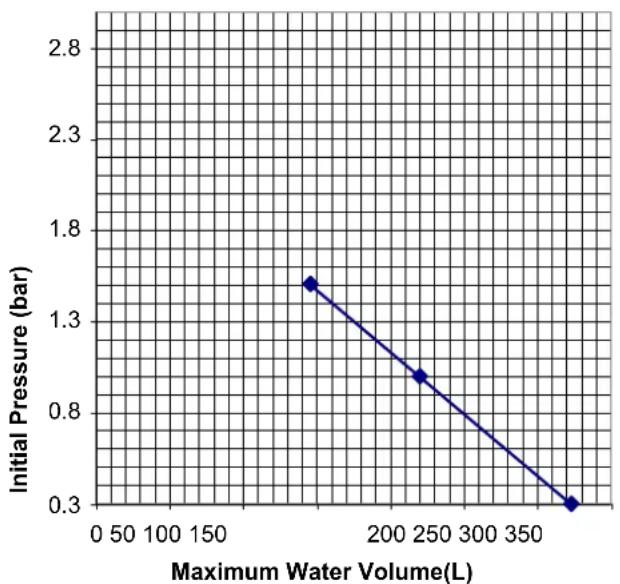
line
| Maximum Water Volume (L) | Initial Pressure (bar) | | :--- | :--- | | 175 | 1.4 | | 250 | 0.9 | | 375 | 0.3 |- This DHW tank is designed for heat pump type heating system. DHW shall be selected according to the requirements in this instruction and on-site use requirements.
- If the selection, installation and wiring are not carried out according to the requirements in this instruction, we would not be responsible for the problems caused by the DHW tank.
- Hot water may cause serious burns. Test water temperature with hands. Use after the water is mixed till proper temperature.
- Connecting of water pipe with tap water pipe should be operated by qualified staff using proper piping material according to local regulations and standards.
- When the high domestic hot water temperature can be a potential risk for human injuries, a mixing valve (field supplied) shall be installed at the hot water outlet connection of the DHW tank. This mixing valve shall secure that the hot water temperature at the hot water tap never rise above a set maximum value. This maximum allowable hot water temperature shall be selected according to the applicable legislation.
When selecting a tank for DHW operation, take into consideration the following points:
- The volume of the tank has to meet with the daily consumption in order to avoid stagnation of water.
- Fresh water must circulate inside the DHW tank water circuit in order to avoid stagnation of water.
- Fresh water must circulate inside the DHW tank water circuit at least one time per day during the first days after the installation has been performed. Additionally, flush the system with fresh water when there is no consumption of DHW during long periods of time.
- Try to avoid long runs of water piping between the tank and the DHW installation in order to decrease possible temperature losses.
- If the domestic cold water entry pressure is higher than the equipment's design pressure, a adequate pressure reducer must be installed to ensure that the maximum pressure is NOT exceeded.
1 Storage capacity
The storage capacity of the DHW tank depends on the daily water demand and the combination method. The daily water demand is estimated with the following calculation formula for consumption:
$$ D _ {i} (T) = D _ {i} \left(6 0 ^ {\circ} C\right) \times \left(6 0 - T _ {i} / T - T _ {i}\right) $$
Where:
D_i(T) : Water demand at T temperature
D_i(60^) : Domestic hot water demand at 60^
T: Temperature of the DHW tank
T_i : Temperature of the inlet cold water
- Calculation of D_i(60^) :
The standard consumption, expressed in daily litres per person and determined by technical installation regulations of each country, is used to calculate the domestic hot water demand at 60 °C, D _i (60 °C). This quantity is then multiplied by
the expected number of users of the installation. In the following example, the domestic hot water demand at 60 °C has been considered as 30 litres per person, in a detached house with 4 residents.
- Calculation of T:
The temperature of the DHW tank refers to the temperature of the accumulated water inside the tank, prior to operation. This temperature is usually between 45 °C and 65 °C. It has been considered as 45 °C in this example.
- Calculation of Ti:
The temperature of the inlet cold water refers to the temperature of the water being supplied to the tank. Since this temperature is usually between 10 °C and 15 °C, it has been considered as 12 °C in this example.
- Example:
$$ D _ {i} (T) = 3 0 \times 4 \times (6 0 - 1 2 / 4 5 - 1 2) = 1 7 4. 5 \text { litres / day } $$
174.5 x 2(*) = 349 litres/day approximate demand of hot water

NOTE
(*) It is recommended to multiply the calculated consumption by two, in case that the installation is in a detached house. This is done to ensure a steady supply of hot water. In the case of a multifamily installation, it is not necessary to increase the forecast of hot water demand, given the lower simultaneity factor.
2 Coil Face Area
The coil face area is a key parameter for DHW tank. To improve the heating efficiency, the coil face area should be adjusted according to the capacity.
The coil face area should be no less than the values listed in the table below.
| Storage Capacity(L) | 100 | 150 | 200 | 250 | 300 |
| Coil Face Area( m^2 ) | 1.5 | 1.5 | 1.8 | 1.8 | 2.0 |

NOTE
Smaller coil face area will lead to worse heating efficiency. In that condition, the heat pump will start and stop frequently which causes more time and more power consumption to heat up the DHW tank.
3 Structural Drawings
The typical structure of the DHW tank is shown as below (only for example):
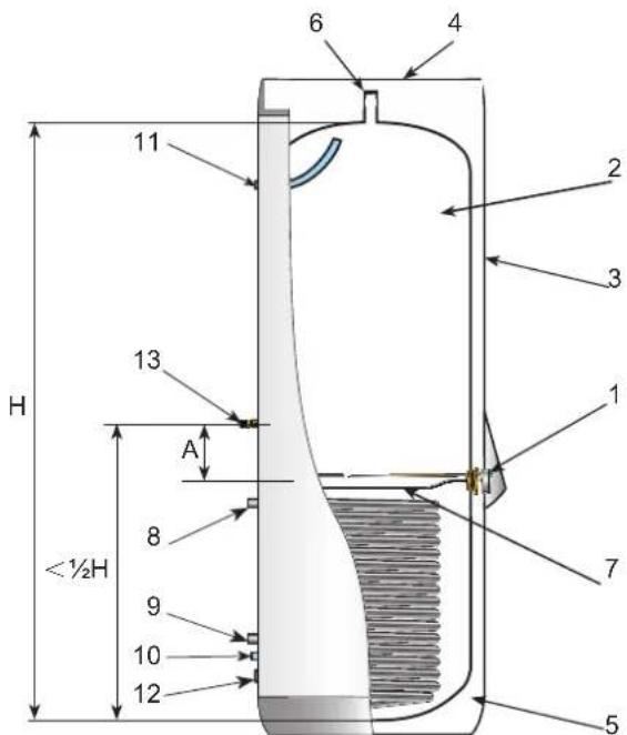
| Ref. | Name |
| 1 | Control panel |
| 2 | Storage tank |
| 3 | External covering |
| 4 | Top covering |
| 5 | Thermal insulation |
| 6 | Temperature pressure valve connection port |
| 7 | DHW electric heater |
| 8 | DHW tank inner coil inlet |
| 9 | DHW tank inner coil outlet |
| 10 | DHW tank water inlet |
| 11 | DHW tank water outlet |
| 12 | Drainage outlet |
| 13 | Thermistor for DHW |
For different storage capacity, the structural design of the DHW tank may be different. The parameters of the typical structure shown in the left are recommended as follows:
| Ref. | Recommended value(mm)* |
| A | Min.150 |
* Please check and adjust according to the actual situation.

NOTE
① The DHW tank including the thermistor, the DHW electric heater and the DHW tank inner coil must be designed and installed in accordance with the local regulation.
② The position of the thermistor is very important. The reasonable position will help to ensure the detection accuracy of the DHW temperature. It is related to the operation of the heat pump.
① The electric heater is necessary to heat up the DHW tank in the following conditions:
- Supplement the heat pump to heat up the DHW tank when the heating capacity of the heat pump is insufficient in low ambient temperature.
- Heat up the DHW tank when the operating conditions exceed the limitation, see details in Section 1 "GENERAL INFORMATION".
② The capacity of the DHW electric heater is related to the storage capacity of the DHW tank, and should be selected according to the following demand.
- Larger capacity of the DHW electric heater is beneficial to heat up the DHW tank, but will consume more power, while smaller capacity of the electric heater will cost more time to heat up the DHW tank.

CAUTION
- The temperature pressure valve and the temperature protection device (covered by the control panel) must be installed according to local regulation and performed by qualified professionals referring to Section "9.4.2 Safety device".
9.4.2 SAFETY DEVICE
1 Temperature pressure valve
A temperature pressure valve which fit with local national requirements should be installed together with DHW tank to avoid the excessive higher temperature and pressure.
- Temperature pressure valve must be tightly connected with drainage pipe. Drainage pipe must be connected as shown below and introduced to building down corner (The water temperature in drainage pipe may be high, note burns).
- Temperature pressure valve in DHW tank can not be connected for other purposes.
- Check temperature pressure valve once half a year. When checking, open temperature pressure valve handle (seen below), temperature pressure valve will smoothly drain water out. The water temperature may be high, note burns. Reset after it is errorless. If drainage fails, contact local dealer for repair.
- Temperature pressure valve and its drainage pipe must keep smooth and not blocked.
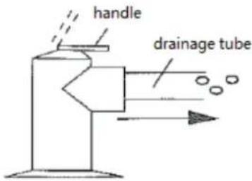
temperature
pressure valve

CAUTION
- If DHW tank is not used for more than 2 weeks, a certain amount of hydrogen will gather in DHW tank. It is recommended to open temperature pressure valve handle or water outlet faucet for several minutes to release hydrogen. However, do not open hot water faucet in dishcleaning machine and washing machine, etc. When hydrogen is released, do not make open flame or operate other electrical apparatus. When gas is released, releasing sound will be heard.
- Temperature pressure valve is used to prevent too high temperature in DHW tank (higher than 94°C, recommended) and water pressure (higher than 0.85MPa, recommended).
2 Temperature protection switch
- When using the DHW electric heater, an Auto Restore Temperature Protection Switch (THe2) has to be installed to prevent the DHW temperature from being heated uncontrollable. When DHW temperature exceeds the protection value, the temperature protection switch opens, and auto restores when DHW temperature reduces below the protection value. The protection value can be selected according to temperature requirement of DHW. The recommended protection value is 80°C.
- Temperature Protection Switch / Temperature fuse (THe1) is connected in the DHW electric heater power supply circuit, which can directly cut off the power supply of DHW electric heater when DHW temperature exceeds the protection value. The recommended protection value is 90 °C.
- The detail wiring diagram of DHW tank is shown in section "10.3.3 Wiring of DHW electric heater".

CAUTION
- Do not install DHW electric heater without temperature protection device.
• Electrical box cover must be opened by qualified electrician.
• Power off before open electrical box cover.
- Recommend installing this equipment to balcony or outdoor at temperature from 0 °C to 43 °C.
- DHW tank is mounted near floor drain to connect temperature pressure valve drainage pipe.
- Do not install DHW tank in place with corrosive gas.
• Installation location is free from frosting.
• Installation location must bear weight of DHW tank containing water. - Ensure dimension of water pipe is above 1 inch (recommend DN40 water pipe), provide enough volume to pipeline and reduced resistance in pipeline system.
- DHW tank is located in a place that is convenient for repair and ensure electrical box is open.
• No accumulated water around installation location. - Arrange filter at water inlet pipe, preventing domestic water contaminated by impurities.
- Ensure DHW tank is full of water before energizing.
Install DHW tank
1) Check DHW tank for complete accessories.
2) When mounted on ground, ensure the bottom of DHW tank is flat and vertically. If mounted in bath room where water exists, recommend installing on a foundation higher than ground, preventing the bottom being soaked by water.
3) To ensure the measurement accuracy, the DHW tank thermistor should be coated with thermal grease. The water proof cable gland (field supplied) is recommended to secure the sensor firmly. The DHW tank sensor must be installed to reach the inner wall of the DHW tank and keep in good contact with it.
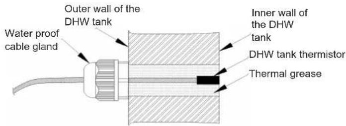

CAUTION
- DHW tank supplies hot water from tap water. Domestic hot water is only used when tap water is connected.
- For safety, do not add ethylene glycol into water circulation. If added, water will be contaminated when heat exchanger coil leaks.
- When water hardness is more than 250-300 ppm, recommend using softened water to reduce DHW tank scale.
- Immediately flush DHW tank with fresh water after installation. Flush once every day in first five days of installation.
- Try to avoid long runs of water piping between the tank and the DHW installation in order to decrease possible temperature losses. If the domestic cold water entry pressure is higher than the DHW tank's design pressure, a pressure reducer must be fitted.
• After used for a while (depend on local water quality and use frequency), clean DHW tank and remove scales.
a. Power off and close water inlet valve.
b. Open water outlet valve and drainage valve to empty DHW tank.

CAUTION
When scales are removed, temperature in DHW tank may be a little high, it should prevent burns or drainage equipment damaged.
c. Close drainage valve after cleaning several minutes with water inlet valve opened. Ensure effluent water is closed after DHW tank is full of water. Power on and get back to work.
• Always check DHW tank and its surroundings has accumulated water or not. If leak, contact local dealer.
9.5 WATER CONTROL
It is necessary to analyse the quality of water by checking pH, electrical conductivity, ammonia ion content, sulphur content, and others. The following is the recommended standard water quality.
| Item | Chilled water system Tendency (1) | |||
| Circulating water (20°C less than) | Supply water | Corrosion | Deposits of scales | |
| Standard Quality pH (25 °C) | 6.8 ~ 8.0 6.8 | ~ 8.0 | ||
| Electrical Conductivity (mS/m) (25 °C) {μS/cm} (25 °C) (2) | Less than 40 Less than 400 | Less than 30 Less than 300 | ||
| Chlorine Ion (mg Cl- /l) | Less than 50 | Less than 50 | ||
| Sulphur Acid Ion (mg H2SO4- /l) | Less than 50 | Less than 50 | ||
| The amount of Acid consumption (pH 4.8) (mg CaCO3/ l) | Less than 50 | Less than 50 | ||
| Total Hardness (mg CaCO3/ l) | Less than 70 | Less than 70 | ||
| Calcium Hardness (mg CaCO3/ l) | Less than 50 | Less than 50 | ||
| Silica L (mg SiO2/ l) Less than 30 | Less than 30 | |||
| Reference Quality Total Iron (mg Fe/l) | Less than 1.0 | Less than 0.3 | ||
| Total Copper (mg Cu/l) | Less than 1.0 | Less than 0.1 | ||
| Sulphur Ion (mg S2- /l) It shall not be detected | ||||
| Ammonium Ion (mg NH4+ /l) | Less than 1.0 | Less than 0.1 | ||
| Remaining Chlorine (mg Cl/l) | Less than 0.3 | Less than 0.3 | ||
| Floating Carbonic Acid (mg CO2/ l) | Less than 4.0 | Less than 4.0 | ||
| Index of Stability 6.8 ~ 8.0 - | ||||

NOTE
- The mark “●” in the table means the factor concerned with the tendency of corrosion or deposits of scales.
- The value showed in “{}” are for reference only according to the former unit.
10 ELECTRICAL AND CONTROL SETTINGS
10.1 GENERAL CHECK
(1) Ensure all electrical apparatus used on site (power switch, circuit breaker, lead, conduit and terminal board) are selected according to technical manual and national electrician standard. Wiring must be made according to national specification.
(2) Check voltage is within rated voltage ± 10%. In case of low voltage, system will not start. In case of high voltage, electrical parts will be burnt out.
(3) Confirm earth wire is connected.
Use wires which are not lighter than the polychloroprene sheathed flexible cord (code designation 60245 IEC 57).
Power supply for unit (TB1 terminal)
| Model | Power supply | Operation mode | Power supply cables EN60335-1 | Transmitting cables EN60335-1 | CB (A) | ELB (n° of poles/A/mA) |
| AHZ-044HCDS1 | 220-240V ~50Hz | — 3 x 2.5 mm | ^2 | 2 x 0.75 mm ^2 | 16 2 | /16/30 |
| With DHW tank heater 3 x | 4.0 mm ^2 | 32 2 | /32/30 | |||
| AHZ-080HCDS1 | — 3 x 4.0 mm | ^2 | 20 2 | /20/30 | ||
| With DHW tank heater 3 x | 6.0 mm ^2 | 40 2 | /40/30 |
Power supply for auxiliary electric heater (TB5 terminal)
| Model | Power supply | Operation mode | Power supply cables EN60335-1 | Transmitting cables EN60335-1 | CB (A) | ELB (n° of poles/A/mA) |
| AHZ-044HCDS1 | 220-240V ~50Hz | With auxiliary electric heater 3 | x 2.5 mm ^2 | 2 x 0.75 mm ^2 | 20 | 2/20/30 |
| AHZ-080HCDS1 | With auxiliary electric heater 3 | x 2.5 mm ^2 | 20 |
CB: Air circuit breaker; ELB: Earth leakage breaker.

CAUTION
- Turn OFF the main power switch of the unit and wait for more than 10 minutes before electrical wiring work or a periodical check is performed.
- The data corresponding to DHW electric heater is calculated in combination with the domestic hot water tank with 3kW DHW electric heater. The DHW electric heater whose power is equal or lower than 3kW, can be driven directly by indoor unit. As for the DHW electric heater which power is over 3kW, the unit can only provide control signal.
• The data corresponding to auxiliary electric heater is calculated as 3kW power.

NOTE
(1) Field wiring shall be in conformity to local laws and regulations, and all wiring operations must be performed by qualified professionals.
(2) Refer to relevant standards for Above-noted power supply cables size.
(3) Where power supply cable is connected through junction box in series, be sure to determine the total current and choose wires based on the table below. Selection according to EN 60335-1.
| Current i (A) | Wire size (mm2) |
| i ≤ 6 | 2.5 |
| 6 < i ≤ 10 | 2.5 |
| 10 < i ≤ 16 | 2.5 |
| 16 < i ≤ 25 | 4 |
| 25 < i ≤ 32 | 6 |
| 32 < i ≤ 40 | 10 |
| 40 < i ≤ 63 | 16 |
| 63 < i | ※1 |
※1: In the case that current exceeds 60A, do not connect cables in series.
(4) As a minimum, the chosen wires shall not be lighter than the polychloroprene sheathed flexible cord (code designation 60245 IEC 57).
(5) The wiring specifications for weak current transmission circuit shall not be lower than that for RVV(S)P shielded wires or equivalent, and the shielding layer shall be grounded.
(6) A switch that can ensure all-pole disconnection shall be installed between power supply and air conditioning unit in such a manner that the contact spacing shall not be less than 3 mm.
(7) Once the power cord is damaged, the dealer or the professionals from designated maintenance department must be contacted in a timely manner for repair and replacement.
(8) For the installation of power cord, the earth wire must be longer than the current-carrying conductor.
10.2 ELECTRICAL WIRING CONNECTION FOR OUTDOOR UNITS
The electrical wiring connection for the unit is shown as follow.
Step1: Remove the screws (9pc) around the service cover.
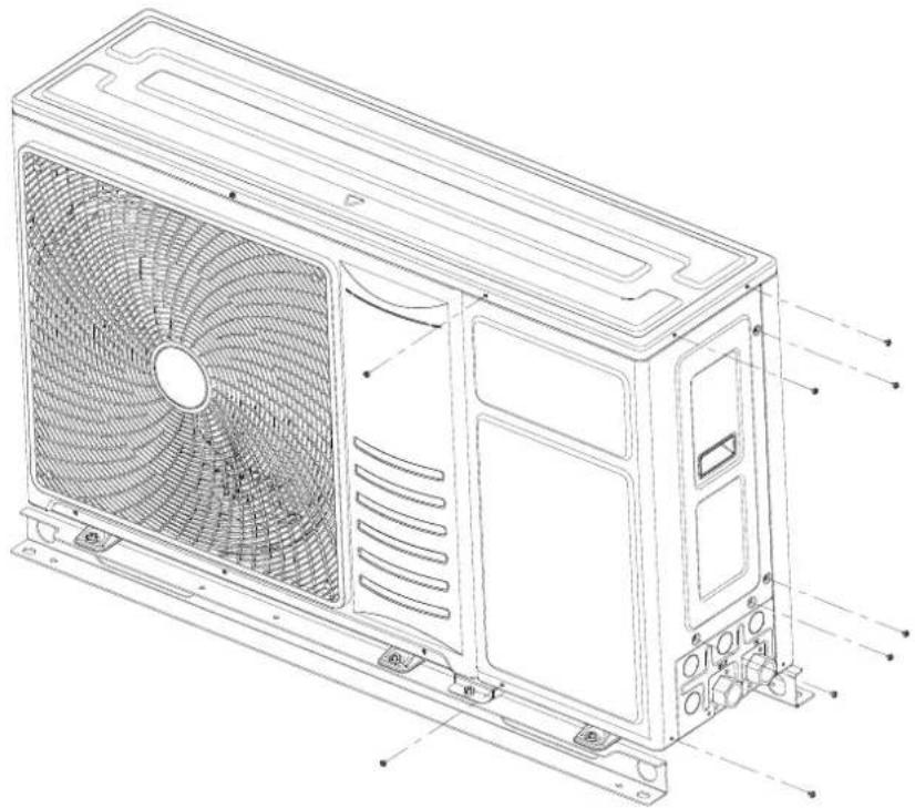
natural_image
Technical line drawing of a multi-chamber HVAC unit with fan blades and mounting brackets (no text or symbols)Step2: Remove the service cover.
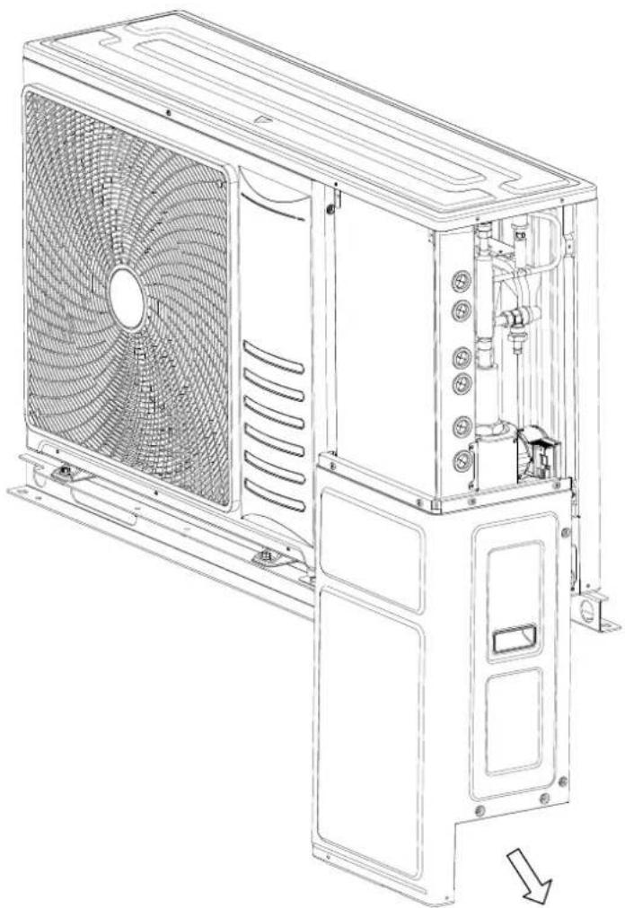
natural_image
Technical line drawing of a multi-chamber HVAC unit with fan blades and internal components (no text or symbols)Step3: Remove the screws (4pc) around the electrical box cover.
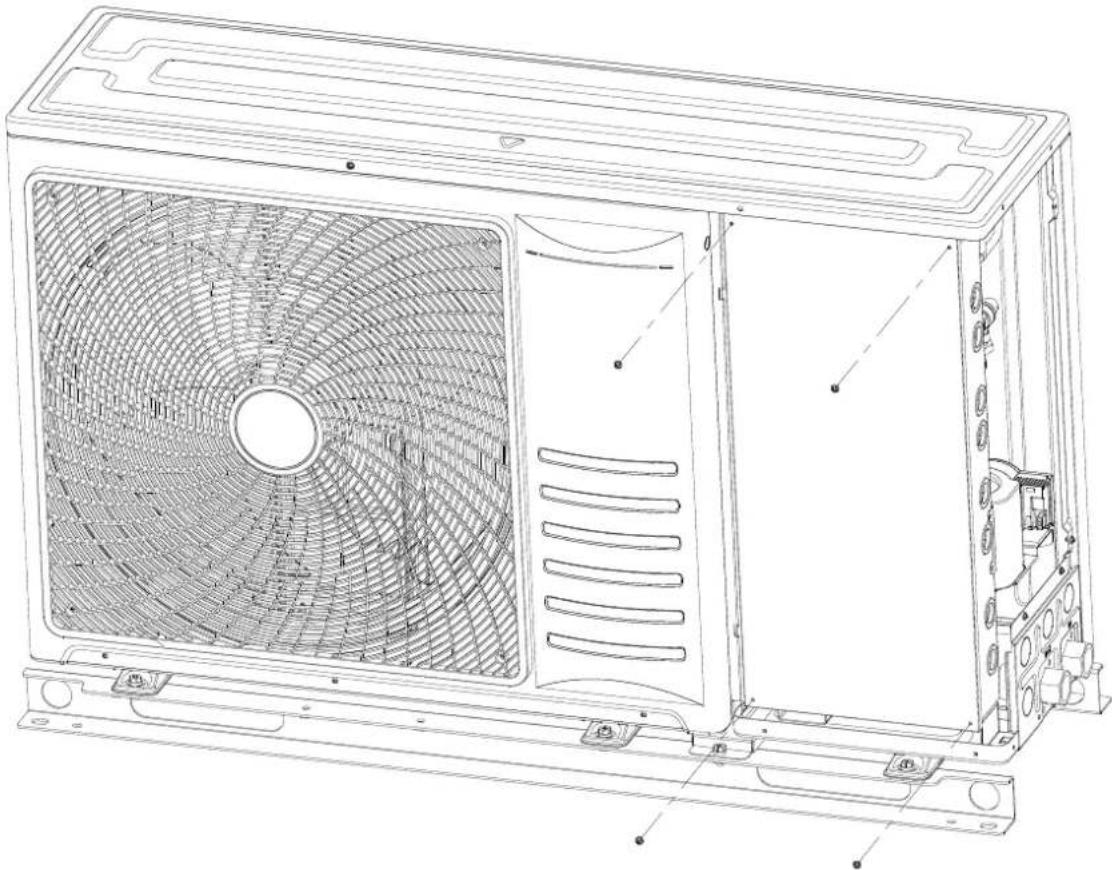
natural_image
Technical line drawing of a large air conditioning unit with fan blades and internal structure (no text or symbols)Step4: Remove the electrical box cover.
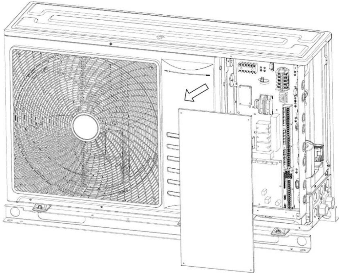
natural_image
Technical line drawing of an air conditioning unit with fan blades and internal components (no text or symbols)Step5: Carry out wiring work as required.
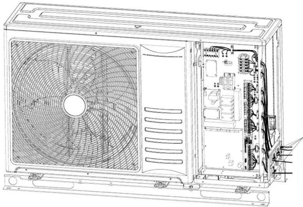
natural_image
Technical line drawing of an internal air conditioning unit with fan blades and internal circuitry (no text or labels)
NOTE
Knock out the holes on the sheet metal as required and put on the rubber rings provided by the factory before wiring connection.
The more detailed wiring connection is shown in the figure below:
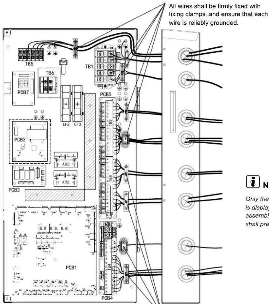

NOTE
Only the structural layout is displayed, the actual assembly of the unit shall prevail.
All wires shall be firmly fixed with fixing clamps, and ensure that each wire is reliably grounded.
10.3 TERMINAL BOARD CONNECTIONS
10.3.1 WIRING OF UNIT AND CONTROLLER
- The transmission is wired to terminals A-B.
- The H-NET wiring system requires only two transmission cables that connect the unit and the controller.
• The shielding layer shall be grounded.
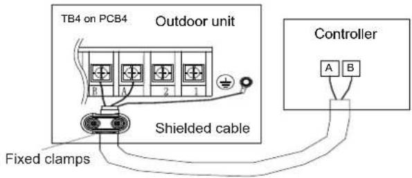
- Use twisted pair cables (0.75 mm ^2 ) for transmission wiring between the unit and controller. The wiring must consist of 2-core wires (Do not use wire with more than 3 cores).
- Use shielded wires for transmission wiring to protect the units from noise interference, with a length of less than 300 m and a size in compliance with local codes. Connect the shielding layer to ground.
- In the event that a conduit tube for field-wiring is not used, fix rubber bushes to the panel with adhesive.
CAUTION
Ensure that the transmission wiring is not wrongly connected to any live part that could damage the PCB.
10.3.2 WIRING OF MAIN POWER SUPPLY
The main power supply connection is wired to the terminal board (TB1) as follows:
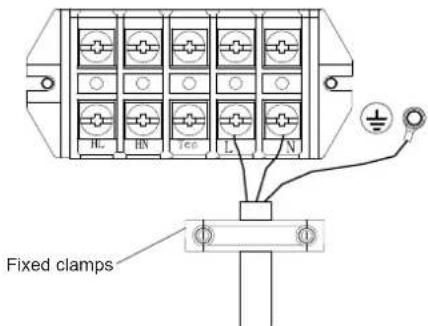
TB: Terminal board CB: Air circuit breaker ELB: Earth leakage breaker
— Power supply cables — Transmission cables ☆ : Field supplied, not contained in the unit
CAUTION
- Connect power line and earth wire to the harness.
- Check and ensure live line and null line of terminal boards in power supply are correctly linked.
If connected inversely, some parts may be damaged.
10.3.3 WIRING OF DHW ELECTRIC HEATER
CAUTION
The electric heater of the DHW tank needs to meet the relevant requirements of local laws and regulations. It is necessary to protect it through a temperature fuse and a temperature protection switch.
1 Electric heater power ≤ 3 kW.
Power line connection should give concern to live line and null line, and be grounded strictly.

2 Electric heater power >3 kW.
When the capacity of the electric heater is greater than 3 kW, the terminal HL/HN only provides control signals to control the ON/OFF of the AC contactor.
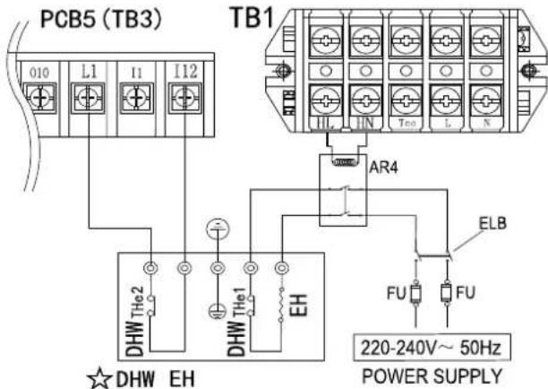
| Codes | Indications | Recommended parameters |
| DHW EH | DHW electric heater assembly | |
| EH | Electric heater | |
| THe1 | Temperature protection switch / Temperature fuseConnected in the DHW electric heater power supply circuit, directly cut off the power supply of DHW electric heater when DHW temperature exceeds the protection value. | Protection value90 °C |
| THe2 | Temperature protection switch (Auto restore)When DHW temperature exceeds the protection value, the temperature protection switch open, and auto restore when DHW temperature reduce below the protection value.The unit can detect this temperature protection switch is open and cuts off the power supply DHW electric heater. | Protection value80 °C |
| AR4 | AC contactor (repeater) | Selection according to EH (DHW) specifications |
| FU | Fuse |

CAUTION
Electrical wiring must be performed by professional technician according to national regulations.
- Correctly mount cable water proof head and electrical box cover, preventing short circuit caused by water intruding into electrical box.
- Thermistor of DHW tank is weak current signal, preventing mixed with strong current signal.
- The DHW tank must have temperature protection devices recommended in this section to ensure the power supply of DHW electric heater can be cut off in time when the DHW temperature is too high.
10.3.4 WIRING OF AUXILIARY ELECTRIC HEATER

CAUTION
The auxiliary electric heater needs to meet the relevant requirements of local laws and regulations. It is necessary to protect it through a temperature fuse and a temperature protection switch.
1 Electric heater power ≤ 3 kW.
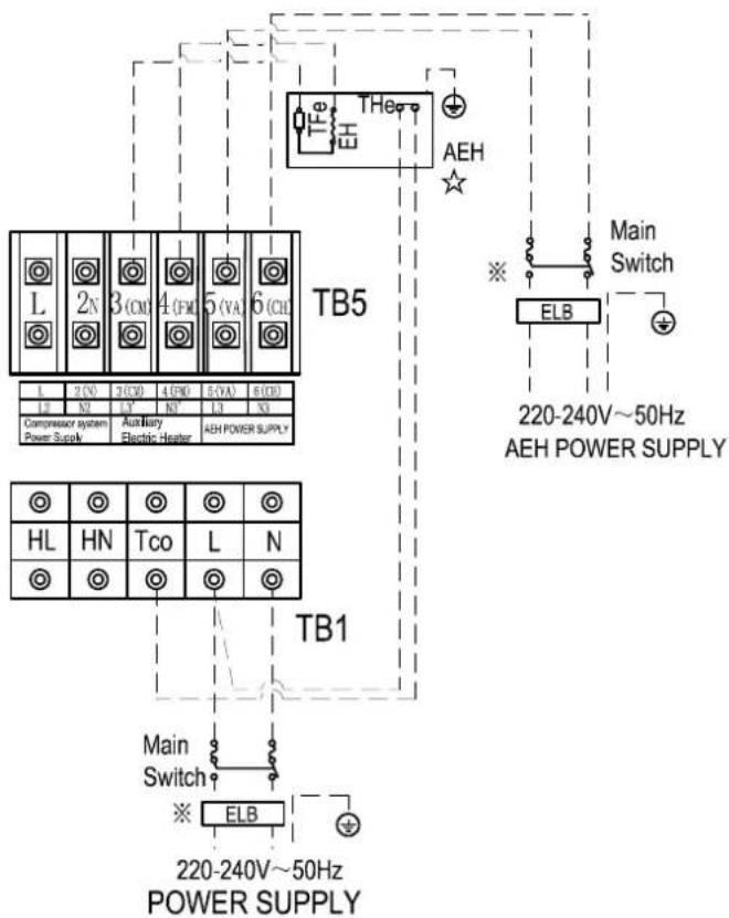
2 Electric heater power >3 kW.
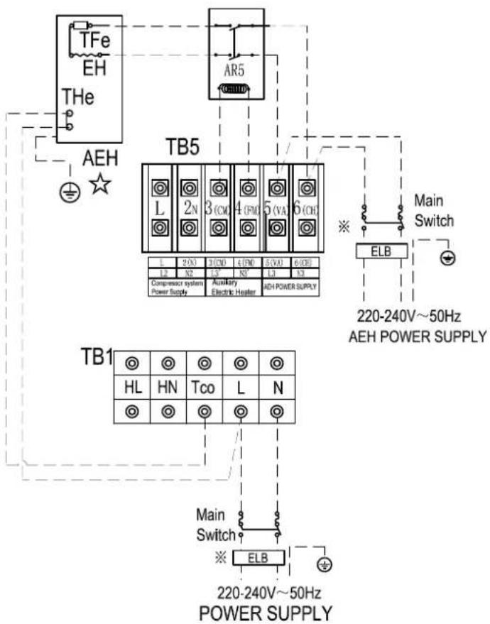

CAUTION
When the power of the electric heater is greater than 3kW, the terminal 3(CM)/4(FM) only provides control signals to control the on and off of the AC contactor.
| Codes | Indications | Recommended parameters |
| AEH | Auxiliary electric heater assembly | |
| EH | Auxiliary electric heater | |
| TFe | Temperature fuse or Temperature control switch | Protection value 90 °C |
| THe | Temperature control switch | Protection value 75 °C |
| AR5 | AC contactor (repeater) | Selection according to EH specifications |
| FU | Fuse |

CAUTION
Electrical wiring must be performed by professional technician according to national regulations.
- Correctly mount cable water proof head and electrical box cover, preventing short circuit caused by water intruding into electrical box.
- The auxiliary electric heater must have temperature protection devices recommended in this section to ensure the power supply of auxiliary electric heater can be cut off in time when the auxiliary electric heater temperature is too high.

CAUTION
Remove the factory-delivered sensor of Tow from original position and fix the sensor just after auxiliary electric heater if the heater is installed on site, as shown in the figure below.
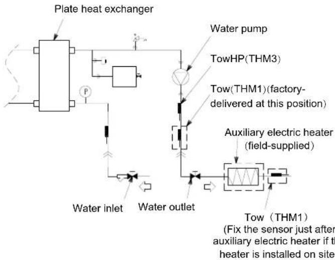
flowchart
graph TD
    A["Plate heat exchanger"] --> B["Water inlet"]
    B --> C["Water outlet"]
    C --> D["Tow (THM1)"]
    D --> E["Auxiliary electric heater (field-supplied)"]
    E --> F["Tow (THM3)"]
    F --> G["Tow(THM1)(factory-delivered at this position)"]
    G --> H["Water pump"]
    H --> I["Water outlet"]
    I --> J["Water inlet"]
    style A fill:#f9f,stroke:#333
    style B fill:#ccf,stroke:#333
    style C fill:#cfc,stroke:#333
    style D fill:#fcc,stroke:#333
    style E fill:#cff,stroke:#333
    style F fill:#ffc,stroke:#333
    style G fill:#cfc,stroke:#333
    style H fill:#fcc,stroke:#333
    style I fill:#cfc,stroke:#333
- Insulate the sensor with the insulation sheet (field-supplied).
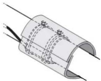
natural_image
Diagram of a flexible cable or wire with dashed internal lines and connectors, no text or symbols present
NOTE
In case that the sensor supplied with unit is not long enough, please make sure that the length extension is properly done avoiding the sensing distortion and that the joint is properly insulated and waterproof to avoid any electrical failure.
Fixing the sensor
- Fix the sensor with insulating aluminum tape (field-supplied) in order to ensure a good heat transference. Make good contact between sensor and pipe.
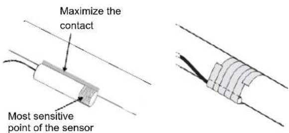
- Put the insulating tape (field-supplied) around the sensor in order to avoid loosening of the sensor after some years.
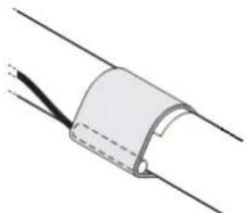
natural_image
Diagram of a curved pipe or tube with dashed lines indicating internal flow or movement (no text or symbols)- Fasten the sensor with 2 cord clamps (field-supplied).
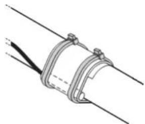
natural_image
Technical line drawing of a mechanical clamp or bracket assembly (no text or symbols)10.4 OPTIONAL INDOOR UNIT WIRING (ACCESSORIES)
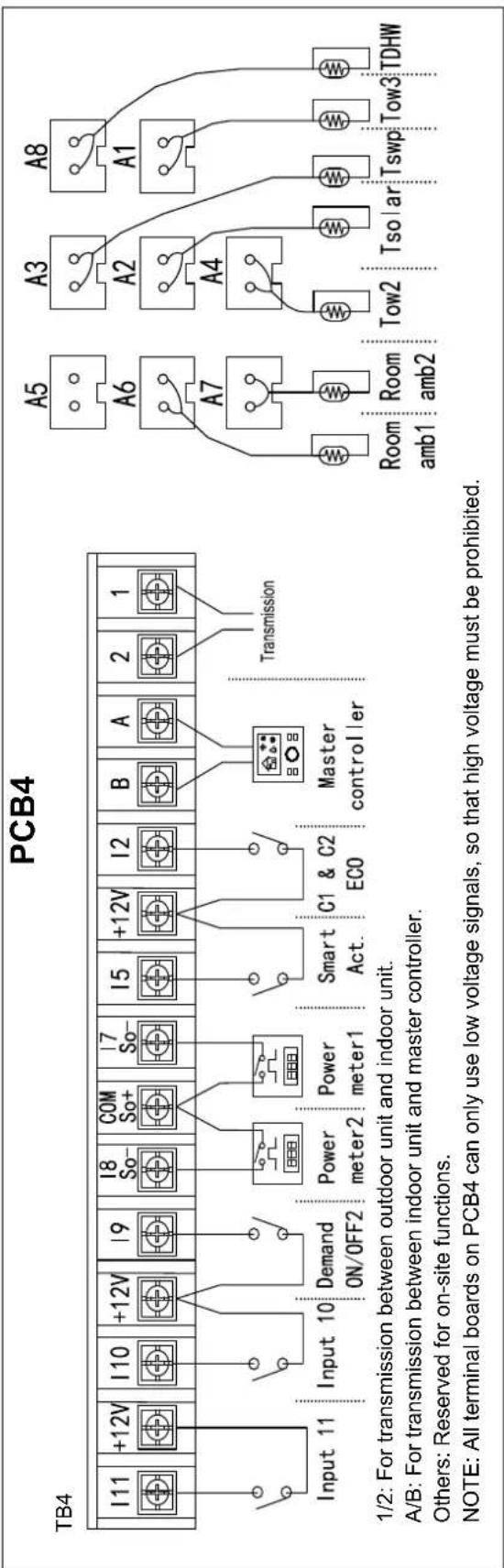
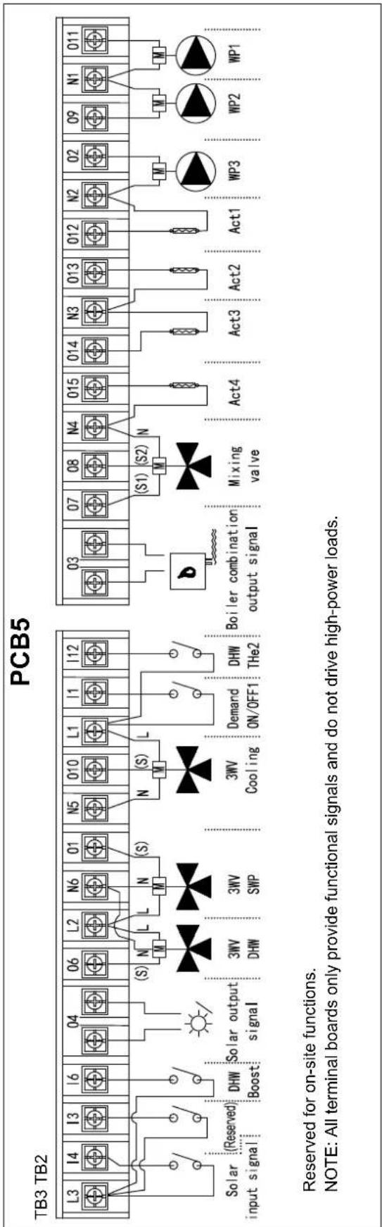
flowchart
graph TD
    subgraph TB3_TB2
        L3["L3"] --> S1["Solar input signal"]
        I4["I4"] --> S1
        I3["I3"] --> S1
        I6["I6"] --> S1
        O4["O4"] --> S1
        O6["O6"] --> S1
        L2["L2"] --> M["M"]
        N6["N6"] --> M
        N1["01"] --> S1
        N5["N5"] --> S1
        O10["010"] --> M
        L1["L1"] --> M
        L11["L1"] --> M
        L12["L12"] --> M
    end

    subgraph PCB5
        O3["O3"] --> S2["Boiler combination output signal"]
        O7["O7"] --> S2
        O8["O8"] --> S2
        N4["N4"] --> M
        N15["015"] --> M
        N14["014"] --> M
        N3["N3"] --> M
        N13["013"] --> M
        N12["012"] --> M
        N2["N2"] --> M
        N20["02"] --> M
        N9["09"] --> M
        N1["N1"] --> M
        N11["011"] --> M

    end

    L3 --> S1
    I4 --> S1
    I3 --> S1
    I6 --> S1
    O4 --> S1
    O6 --> S1
    L2 --> M
    N6 --> M
    N1 --> M
    N5 --> M
    O10 --> M
    L1 --> M
    L12 --> M

    S1 --> M
    S2 --> M
    M --> M
    M --> M
    M --> M

    S1 --> M
    S2 --> M

    M --> M
    M --> M

    style TB3_TB2 fill:#f9f,stroke:#333
    style PCB5 fill:#ccf,stroke:#333

 note bottom of TB3 TB2: Reserved for on-site functions.
NOTE: All terminal boards only provide functional signals and do not drive high-power loads.

NOTE
Inputs and outputs printed on the board are the setting before shipment options. By means of the master controller, some other inputs and output functions can be configured and used.
Input - Setting before shipment
| Mark | Description | Default settings Available input codes | Specification | Terminals | |
| I1 | Input 1 | i - 08(Demand ON/OFF 1) | i - 00~17(Except i - 07/12) | I1, L1on TB3 | Closed/Open220-240V ~ 50/60Hz |
| I2 | Input 2 | i - 13(Cycle 1 and 2 ECO mode) | i - 00~17(Except i - 07/12) | I2, +12Von TB4 | Closed/Open12V DC |
| I3 | Input 3 | i - 00(No function) | i - 00~17(Except i - 07/12) | I3, L3on TB3 | Closed/Open220-240V ~ 50/60Hz |
| I4 | Input 4 | i - 04(Solar in) | i - 00~17(Except i - 07/12) | I4, L3on TB3 | Closed/Open220-240V ~ 50/60Hz |
| I5 | Input 5 | i - 02(Smart Act.) | i - 00~17(Except i - 07/12) | I5, +12Von TB4 | Closed/Open12V DC |
| I6 | Input 6 | i - 06(DHW Boost) | i - 00~17(Except i - 07/12) | I6, L3on TB3 | Closed/Open220-240V ~ 50/60Hz |
| I7 | Input 7 | i - 07(Power meter 1) | i - 00~17 | I7, COMon TB4 | Closed/Open12V DC |
| I8 | Input 8 | i - 12(Power meter 2) | i - 00~17 | I8, COMon TB4 | Closed/Open12V DC |
| I9 | Input 9 | i - 09(Demand ON/OFF 2) | i - 00~17(Except i - 07/12) | I9, +12Von TB4 | Closed/Open12V DC |
| I10 | Input 10 | i - 00(No function) | i - 00~17(Except i - 07/12) | I10, +12Von TB4 | Closed/Open12V DC |
| I11 | Input 11 | i - 00(No function) | i - 00~17(Except i - 07/12) | I11, +12Von TB4 | Closed/Open12V DC |
Input - All input codes descriptions:
| Input codes Mark Description | ||
| i - 00 No Function - | ||
| i - 02 | Smart Act./SG Ready Input 1 | This function must be used to stop or limit the heat pump and Auxiliary electric heater when restricted by Electric company. It allows an external Smart switch device to switch off or reduce consumption of the heat pump and Auxiliary electric heater during time of peak electricity demand.In case of using Smart Grid application, this input is used as a digital input 1 and allows four different operating modes. |
| i - 03 | Swimming poolDemand ON/OFF | Optional input signal can be configured as function of "Swimming pool Demand ON/OFF" to operate SWP. Switch ON/OFF of SWP can also be controlled by master controller.Closed: Start SWP operation (Switch ON and Demand ON)Open: Stop SWP operation (Switch OFF and Demand OFF) |
| i - 04 Solar in | In case of combining Unit with solar panels, this input is used as a feedback for solar station ready operation.Closed: Solar in ON to trigger solar pump operation ONOpen: Solar in OFF to trigger solar pump operation OFF | |
| i - 05 Forced Heating/Cooling | Heating/cooling can be changed by an input of an external contact signal.Heating/cooling can also be changed over by master controller.Closed: Heating modeOpen: Cooling mode | |
| i - 06 DHW Boost | With this function enabled, it is possible to request a heating up of the DHW when user requires an instantaneous delivery of DHW. Triggering input signal can also Switch ON DHW. | |
| i - 07 Power meter 1 | Input used as kW/h pulse count for Energy data recording, used to count energy data or the total energy data. | |
| i - 08 Demand ON/OFF 1 | Optional input signal can be configured as function of "Demand ON/OFF 1" or "Demand ON/OFF 2" and selected as room thermostat.Closed: Corresponding room thermostat Switch ON and Thermo ON.Open: Corresponding room thermostat Switch OFF and Thermo OFF.Corresponding room thermostat can also be Switch ON/OFF by Rooms function on Master controller. | |
| i - 09 Demand ON/OFF 2 | ||
| i - 10 Forced heating | Forced Heating mode by input of contact signal, Heating can also be changed over by master controller.Closed: Forced Heating modeOpen: No action | |
| i - 11 Forced cooling | Forced Cooling mode by input of contact signal, Cooling can also be changed over by master controller.Closed: Forced Cooling modeOpen: No action | |
| i - 12 Power meter 2 | Input used as kW/h pulse count for Energy data recording, used to count energy data or the total energy data. | |
| i - 13 Cycle 1 and 2 ECO mode | Cycle 1 and Cycle 2 Water ECO offset. Current water temperature setting is reduced or increased by the indicated parameter in space heating mode or space cooling mode.Closed: Cycle 1 and Cycle 2 Water ECO offset enabledOpen: Cycle 1 and Cycle 2 Water ECO offset disabled | |
| i - 14 Cycle 1 ECO mode | Cycle 1 Water ECO offset. Current water temperature setting is reduced or increased by the indicated parameter in space heating mode or space cooling mode.Closed: Cycle 1 Water ECO offset enabledOpen: Cycle 1 Water ECO offset disabled | |
| i - 15 Cycle 2 ECO mode | Cycle 2 Water ECO offset. Current water temperature setting is reduced or increased by the indicated parameter in space heating mode or space cooling mode.Closed: Cycle 2 Water ECO offset enabledOpen: Cycle 2 Water ECO offset disabled | |
| i - 16 Force OFF | Force OFF the unit include Water Cycle 1, Water Cycle 2, DHW and SWP. Switch ON/OFF of different function can also be controlled by master controller.Closed: Forced OFF the unit include Water Cycle 1, Water Cycle 2, DHW and SWP.Open: No action | |
| i - 17 SG Ready Input 2 | In case of using Smart Grid application, this input is used as a digital input 2 and allows four different operating modes. | |

CAUTION
Functions i - 05(Forced Heating/Cooling) /Functions i - 10(Forced heating)/Functions i - 11(Forced cooling) cannot be used at the same time.
Output - Setting before shipment
| Mark | Description | Default settings Available output codes | Specification | Terminals | ||
| O1 | Output 1 | o - 01(3WV SWP) | o - 00 ~ 29(Except o - 02/08/17/21) | Power supply | L2, N6on TB3 | ON/OFF220-240V ~ 50/60HzMax. 1.0A |
| Signal line | O1on TB3 | |||||
| O2 | Output 2 | o - 02(WP3) (Except o - 17) | o - 00 ~ 29 | O2, N2on TB2 | ON/OFF220-240V ~ 50/60HzMax. 1.0A | |
| O3 | Output 3 | o - 03(Boiler combination) | o - 00 ~ 29(Except o - 02/08/17/21) | O3on TB2 | Free voltageMax. 1.0A | |
| O4 | Output 4 | o - 04(Solar out) | o - 00 ~ 29(Except o - 02/08/17/21) | O4on TB3 | Free voltageMax. 1.0A | |
| O5 | Output 5 | o - 17(DHW Electric Heater) | o - 00 ~ 29 | WL, WNon TB1 | ON/OFF220-240V ~ 50/60HzMax. 15A | |
| O6 | Output 6 | o - 18(3WV DHW) | o - 00 ~ 29(Except o - 02/08/17/21) | Power supply | L2, N6on TB3 | ON/OFF220-240V ~ 50/60HzMax. 1.0A |
| Signal line | O6on TB3 | |||||
| O7 | Output 7 | o - 19(Mixing valve Close) | o - 00 ~ 29(Except o - 02/08/17/21) | O7, N4on TB2 | ON/OFF220-240V ~ 50/60HzMax. 1.0A | |
| O8 | Output 8 | o - 20(Mixing valve Open) | o - 00 ~ 29(Except o - 02/08/17/21) | O8, N4on TB2 | ON/OFF220-240V ~ 50/60HzMax. 1.0A | |
| O9 | Output 9 | o - 21(WP2) (Except o - 17) | o - 00 ~ 29 | O9, N1on TB2 | ON/OFF220-240V ~ 50/60HzMax. 1.0A | |
| O10 | Output 10 | o - 22(3WV Cooling) | o - 00 ~ 29(Except o - 02/08/17/21) | Power supply | L1, N5on TB3 | ON/OFF220-240V ~ 50/60HzMax. 1.0A |
| Signal line | O10on TB3 | |||||
| O11 | Output 11 | o - 08(WP1) (Except o - 17) | o - 00 ~ 29 | O11, N1on TB2 | ON/OFF220-240V ~ 50/60HzMax. 1.0A | |
| O12 | Output 12 | o - 23(Act1) | o - 00 ~ 29(Except o - 02/08/17/21) | O12, N2on TB2 | ON/OFF220-240V ~ 50/60HzMax. 1.0A | |
| O13 | Output 13 | o - 24(Act2) | o - 00 ~ 29(Except o - 02/08/17/21) | O13, N3on TB2 | ON/OFF220-240V ~ 50/60HzMax. 1.0A | |
| O14 | Output 14 | o - 25(Act3) | o - 00 ~ 29(Except o - 02/08/17/21) | O14, N3on TB2 | ON/OFF220-240V ~ 50/60HzMax. 1.0A | |
| O15 | Output 15 | o - 26(Act4) | o - 00 ~ 29(Except o - 02/08/17/21) | O15, N4on TB2 | ON/OFF220-240V ~ 50/60HzMax. 1.0A | |
Output - All output codes descriptions:
| Output codes | Mark Description | |
| o - 00 No | Function | - |
| o - 01 3WV | SWP | In case of combining Unit with swimming pool, this output is used to drive 3-way valve diverting to the swimming pool heat exchanger. Output ON signal when swimming pool function is operating. |
| o - 02 WP3 | In case of combining Unit with hydraulic separator, this output is used to drive relay of water pump 3. | |
| o - 03 | Boiler combination | In case of combining Unit with boiler, this output is used to Start/Stop it. |
| o - 04 Solar out | In case of combining Unit with solar panel, this output is used to drive relay of solar pump. | |
| o - 05 Alarm signal Output ON signal when an Alarm Code is existence. | ||
| o - 06 SWP signal Output ON signal in case that Swimming pool function is demand ON. | ||
| o - 07 Cooling signal Output ON signal in case that Space Cooling is Thermo-ON. | ||
| o - 08 WP1 | In case of the pipeline connected to the unit is long leading to low water flow rate, this output is used to drive relay of a extra WP1 that can be cascaded with inside EC WP1 to offer additional hydraulic head. The extra WP1 works equally with inside EC WP1. | |
| o - 09 Heating signal Output ON signal in case that Space Heating is Thermo-ON. | ||
| o - 10 DHW signal Output ON signal in case that DHW is demand ON or DHW Electric Heater is ON. | ||
| o - 11 | Solar overheat | Output ON signal in case that solar panels overheat protection is activated. |
| o - 12 | Defrost | Output ON signal in case that the outdoor unit is defrosting. |
| o - 13 | DHW re-circulation pump | Output ON signal to drive relay of a re-circulation pump in case of re-circulation pump is available for DHW tank. |
| o - 14 Heater relay 1 Copy ON/OFF signal of Auxiliary electric heater output terminal 1. | ||
| o - 15 Heater relay 2 Copy ON/OFF signal of Auxiliary electric heater output terminal 2. | ||
| o - 16 | c1 water ON/OFF | Output ON signal in case that Water Cycle1 switch ON. |
| o - 17 | DHW Electric Heater | Output ON signal in case the DHW Electric Heater is Enabled and meet the ON conditions. |
| o - 18 3WV | DHW | In case of combining Unit with DHW, this output is used to drive 3-way valve diverting to the sanitary tank inner coil. Output ON signal when DHW function is operating. |
| o - 19 | Mixing valve Close | Mixing valve has two operation terminals of closing valve and opening valve. Optional output signal need be configured as function of "Mixing valve Close" and "Mixing valve Open" to drive mixing valve. |
| o - 20 Mixing valve Open | ||
| o - 21 WP2 | When Water Cycle 2 is available Optional Output signal need be configured to drive relay of water pump 2. | |
| o - 22 | 3WV Cooling | In case of combining Unit with cooling fan coil, this output is used to drive 3-way valve diverting to cooling fan coil. Output ON signal when space cooling is operating. |
| o - 23 | Act1 | Room actuators, output ON signal in case the corresponding Room Thermostat is Thermo ON (heating and cooling). And also meet follow condition Room actuators also Output ON:1 Air purge2 Anti-freezing3 Screed Drying4 Retry operation due to anti freezing (alarm-76 , d1-31, d1-03)5 Outdoor Unit defrost without Room Thermostat Thermo ON6 Overrun after requiring OFF |
| o - 24 | Act2 | |
| o - 25 | Act3 | |
| o - 26 | Act4 | |
| o - 27 | Act5 | |
| o - 28 | Act6 | |
| o - 29 | Act7 | |
Auxiliary sensor - Setting before shipment
| Mark | Description | Default settings Available auxiliary sensor codes | |
| A1 | Auxsensor 1 | a - 01 (Tow3) | a - 00 ~ 13 |
| A2 | Auxsensor 2 | a - 03 (Tsolar) | a - 00 ~ 13 |
| A3 | Auxsensor 3 | a - 02 (Tswp) | a - 00 ~ 13 |
| A4 | Auxsensor 4 | a - 05 (Tow2) | a - 00 ~ 13 |
| A5 | Auxsensor 5 | a - 00 (No Function) | a - 00 ~ 13 |
| A6 | Auxsensor 6 | a - 07 (Room_amb1) | a - 00 ~ 13 |
| A7 | Auxsensor 7 | a - 08 (Room_amb2) | a - 00 ~ 13 |
Auxiliary sensor codes - All Auxiliary sensor codes descriptions:
| Auxiliary sensor codes | Mark Description | |
| a - 00 No Function - | ||
| a - 01 | Tow3 | This sensor is used in case to combine Unit with hydraulic separator to detect Hot water temperature detection of hydraulic separator. |
| a - 02 Tswp | In case of combining Unit with swimming pool, this sensor is used to detect swimming pool water temperature. | |
| a - 03 Tsolar | In case of combining Unit with solar panels, this sensor is used to Detect Hot water temperature of solar panels. | |
| a - 04 Ta_ao | Optional Second Outdoor Ambient Temperature sensor accessory can be connected to the Auxiliary sensor in case that the heat pump is located in a non-suitable position for this measurement. | |
| a - 05 | Tow2 | When Water Cycle 2 is available, auxiliary sensor need be configured as function of "Tow2" to detect outlet water temperature of Water Cycle 2. |
| a - 06 duty | Used to detect duty signal when duty signal control is Enabled, the duty signal type can be 0-10V, 0-5V or 10-20mA. | |
| a - 07 Room_amb1 | Rooms function on master controller is selected as room thermostat, and in this scenario, auxiliary sensor can be configured as function of "Room_amb1-7", and can be selected as room temperature detection of specific room. | |
| a - 08 Room_amb2 | ||
| a - 09 Room_amb3 | ||
| a - 10 Room_amb4 | ||
| a - 11 Room_amb5 | ||
| a - 12 Room_amb6 | ||
| a - 13 Room_amb7 | ||

DANGER
- Do not connect the power supply to the unit prior to filling the space heating circuit (and DHW circuit if it were the case) with water and checking water pressure and the total absence of any water leakage.
- Do not connect or adjust any wiring or connections unless the main power switch is OFF.
- When using more than one power source, check and ensure that all of them are turned OFF before operating the unit.
- Avoid wiring installation in contact with the refrigerant pipes, water pipes, edges of plates and electrical components inside the unit to prevent damage, which may cause electric shock or short circuit.

CAUTION
- Turn OFF the main power switch to the unit and wait for more than 10 minutes before electrical wiring work or a periodical check is performed.
- Check to ensure that the outdoor fan have stopped before electrical wiring work or a periodical check is performed.
• Use a dedicated power circuit for the unit. Do not use a power circuit shared with the unit or any other appliance. - Make sure that all wiring and protection devices are properly selected, connected, identified and fixed to the corresponding terminals of the unit, specially the protection (earth) and power wiring, taking into account the applicable national and local regulations. Establish proper earthing; Incomplete earthing may cause electrical shock.
- Protect the unit against theentry of small animals (like rodents) which could damage the drain pipe and any internal wire or any other electrical part, leading to electric shock or short-circuit.
- Keep a distance between each wiring terminal and attach insulation tape or sleeve as shown in the figure.
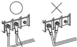
natural_image
Pure electrical circuit lines without any symbolsTape or sleeve
- Tightly secure the power source wiring using the cord clamp inside the unit.
- Check to ensure that the electrical resistance is more than 1 megohm, by measuring the resistance between ground and the terminal of the electrical parts. If not, do not operate the system until the electrical leakage is found and repaired.
- The DHW heater is an accessory which is field-supplied. When the DHW heater is being installed, the power supply cables must be reselected according to the actual load current.
10.5 WIRING SIZE AND MINIMUM
REQUIREMENTS OF THE PROTECTION DEVICES
(1) Connect the power supply wires and the earth wire to the terminal board in the electrical control box refer to chapter 10.2.
(2) Do not wire in front of the fixing screw of the service panel. If do, the screw can not be removed.
(3) Use shielded twist pair for controller.

CAUTION
• The tightening torque of each screw shall be as follows.
M4: 1.0 to 1.3 N·m
M5: 2.0 to 2.5 N·m
M6: 4.0 to 5.0 N·m
M8: 9.0 to 11.0 N·m
M10: 18.0 to 23.0 N·m
Keep the above tightening torque when wiring work.

CAUTION
- Ensure specifically that there is an Earth Leakage Breaker (ELB) installed for the units.
- If the installation is already equipped with an Earth Leakage Breaker (ELB), ensure that its rated current is large enough to hold the current of the units.

NOTE
• Electric fuses can be used instead of magnetic Circuit Breakers (CB). In that case, select fuses with similar rated values as the CB.
- The Earth Leakage Breaker (ELB) mentioned on this manual is also commonly known as Residual Current Device (RCD) or Residual Current Circuit Breaker (RCCB).
• The Circuit Breakers (CB) are also known as Thermal-Magnetic Circuit Breakers or just Magnetic Circuit Breakers (MCB).
- Total wiring length for controller can be extended up to 500m. If total wiring length less than 30m, it is possible to use the normal wiring (0.3mm ^2 ) except shielded twist pair.
10.6 SETTING OF DIP SWITCHES

NOTE
- The mark "■" indicates the dip switches positions.
- No mark "■" indicates pin position is not affected.
• The figures show the settings before shipment or after selection. - "Not used" means that the pin must not be changed. A malfunction might occur if changed.

CAUTION
Before setting dip switches, first turn the power supply OFF and then set the position of dip switches. If the switches are set without turning the power supply OFF, the contents of the setting are invalid.
10.6.1 DIP Switch Setting of PCB1
(1) DSW1: Unit model setting No setting is required.
| Setting before shipment | 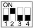 |
(2) DSW2: Unit capacity setting No setting is required.
| Setting before shipment | 044(2.0HP) 080(3.0HP) | |
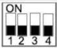 | 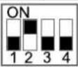 | |
(3) DSW3: Additional setting
| Setting before shipment | 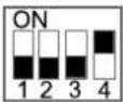 |
| ON: Cancel 70 alarm(Water pressure abnormality) | 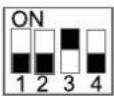 |
| Antifreeze settingsON: Whole water cycle does antifreeze.OFF: Only primary cycle does antifreeze. | 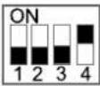 |
(4) DSW4: Additional setting
| Setting before shipment | 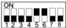 |
| Water pump forced ON | 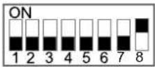 |
| Auxiliary electric heater forced OFF | 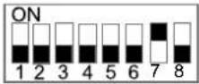 |
| ON: Antifreeze setting is enabledOFF: Antifreeze setting is disabled | 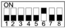 |
| Water pump mode when Thermo OFFON: Operate constantlyOFF: Operate periodically | 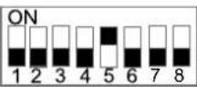 |
| Manual emergency settingON: Manual emergency enabledOFF: Manual emergency disabled | 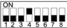 |
| DHW electric heater allowance settingON: DHW electric heater forced OFF cancellingOFF: DHW electric heater forced OFF | 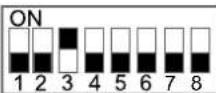 |
| DHW 3-way valve forced ON | 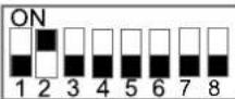 |
| Air purge start |
(5) DSW5: Additional setting
| Setting before shipment | 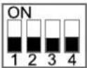 |
| ON: Cancel 75/78 alarm(Water pump abnormalities) | 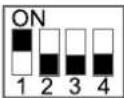 |
| ON: WP3 operates in space cooling mode. | 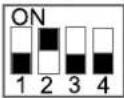 |
(6) DSW6: Fuse reset
| Setting before shipment |  |
(7) DSW7: Not used
| Setting before shipment | 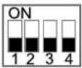 |
(8) DSW8: Refrigeration system No. setting Setting is required. Use binary encoding method.
| Setting before shipment | 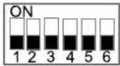 |
Max No.63 are available to set when all the equipment are connected to corresponding central control system. Ex.) Set refrigeration system no. as 8.
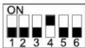
(9) DSW9: Water module No. setting No setting is required.
| Setting before shipment | 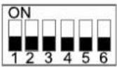 |
10.6.2 DIP Switch Setting of PCB7
(1) DSW1: Unit model setting No setting is required.
| Setting before shipment | 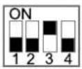 |
(2) DSW3: Unit capacity setting No setting is required.
| Setting before shipment | 044(2.0HP) | 080(3.0HP) |
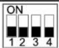 | 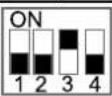 |
(3) DSW6: Refrigeration system No. setting Setting is required. Use binary encoding method.
| Setting before shipment | 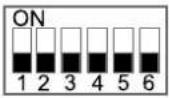 |
Max No.63 are available to set when all the equipment are connected to corresponding H-NET. Ex.) Set refrigeration system no. as 8.
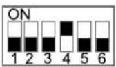
11 TEST RUN

NOTE
NEVER operate the unit without careful inspection.
11.1 CHECKLIST BEFORE TEST RUN
Do NOT operate the system before the following checks are OK:
| You have read the complete installation instructions of the unit and master controller carefully. | ☐ |
| The unit is properly mounted. | ☐ |
| The following field wiring has been carried out according to this document and the applicable legislation:· Between the local power supply and the unit· Between the unit and the valves (if applicable)· Between the unit and the room thermostat (if applicable)· Between the unit and the DHW tank (if applicable) | ☐☐☐☐☐ |
| The system is properly earthed and the earth terminals are tightened. | ☐ |
| The fuses or locally installed protection devices are installed according to this document, and have NOT been bypassed. | ☐ |
| The power supply voltage matches the voltage on the Nameplate of the unit. | ☐ |
| There are NO loose connections or damaged electrical components in the electrical box. | ☐ |
| There are NO damaged components or squeezed pipes on the inside of the units. | ☐ |
| Only for DHW tank with electric heater:Temperature protection switch (Auto restore) has been already wired.Temperature protection switch / Temperature fuse has been already wired. | ☐ |
| There are NO refrigerant leaks. | ☐ |
| The water pipes are thermally insulated. | ☐ |
| There is NO water leakage inside the unit. | ☐ |
| The shut-off valves are properly installed and fully open. | ☐ |
| The air purge valve is open (at least 2 turns). | ☐ |
| The safety valve purges water when open. | ☐ |
| The minimum water volume is guaranteed in all conditions. See section 9.2. | ☐ |
| The DHW tank is filled completely. | ☐ |

CAUTION
- The unit starts only when all check points are cleared up.
- Pay attention when system is running:
(A) Do not touch any parts of discharge pipelines, because the discharge temperature of compressor can be more than 90°C.
(B) Do not press AC contactor button, otherwise serious accident may be caused.
- Do not touch any electrical components within 10 minutes after main power supply is cut off.
11.2 CHECKLIST DURING TEST RUN
| The minimum flow rate during electric heater/defrost operation is guaranteed in all conditions. See section "9.2 Requirements and recommendations for hydraulic circuit". | |
| To perform an air purge. | |
| To perform a test run. | |
| To perform an actuator test run. | |
| Underfloor screed drying functionThe underfloor screed drying function is started (if necessary). |

CAUTION
- When performing test run of floor heating, higher temperature in indoor unit (up to 55^ ) will damage floors due to expansion and contraction. Recommend it is within 30 minutes.
- Use the controller to start test run (refer to the manual of master controller).
- It is normal that after indoor unit is energized, it may directly enter anti-freezing running mode, and water pump automatically runs if outdoor temperature is very low.
11.3 CHECK THE MINIMUM FLOW RATE
| 1 | Check the hydraulic configuration to find out which space heating loops can be closed by mechanical, electronic, or other valves. | — |
| 2 | Close all space heating loops that can be closed. | — |
| 3 | Start the pump test run . See setting of DSW4-8 in section "10.6.1 DIP Switch Setting of PCB1". | — |
| 4 | Read out the flow rate and modify the bypass valve setting to reach the minimum required flow rate + 2L/min. | — |
12 MAIN SAFETY DEVICES
◆ Compressor protection
High pressure switch:
This switch cuts out the operation of the compressor when the discharge pressure exceeds the setting.
◆ Fan motor protection
When the thermistor temperature is reached to the setting, motor output is decreased. The other way, when the temperature becomes lower, limitation is cancelled.
| Model | 044(2.0HP) 080(3.0HP) | ||
| For compressor | |||
| Pressure switches | - | Automatic Reset, Non-Adjustable(each one for each compressor) | |
| Fuse | - | 30A (Inside PCB6) | |
| CCP Timer | - | Non-Adjustable | |
| Setting Time | min. | 3 | |
| For condenser fan motor | |||
| Internal Thermostat | - | Automatic Reset, Non-Adjustable(each one for each motor) | |
| For Control Circuit | |||
| Fuse on Main Circuit of Indoor part | - | 10A (Inside PCB1) | |
| Fuse on DHW Electric Heater | - | 20 | |
| Fuse on Auxiliary Electric Heater | - | 20 | |
13 TECHNICAL PARAMETERS
| Outdoor unit: Indoor unit: | AHZ-044HCDS1 | / | |||||
| Outdoor side heat exchanger of air conditioner/heat pump:air | |||||||
| Indoor side heat exchanger of air conditioner/heat pump:water | |||||||
| Type: compressor driven vapour compression | |||||||
| Driver of compressor:electric motor | |||||||
| Indication if the heater is equipped with a supplementary heater:no | |||||||
| Parameters shall be declared for the average heating season | |||||||
| Item Symbol Valu | e Unit Item | Symbol V | alue unit | ||||
Heating
| Parameters shall be declared for: | Low temperature application | ||||||
| Indoor heat exchanger: | Variable outlet | ||||||
| Rated heating capacity | P_rated,h | 4.61 kW | Seasonal space heating energy efficiency | ηs,h 204 % | |||
| Declared heating capacity for part load at indoor temperature 20 °C and outdoor temperature Tj | Declared coefficient of performance (*)/Average season, at indoor temperature 20 °C and outdoor temperature Tj | ||||||
| Tj = -7 °C | Pdh 4.05 kW Tj = -7 | °C | COPd 3.26 — | ||||
| Tj = 2 °Dh 2.48 kW Tj = 2 COPd 5.02 — | °C | ||||||
| Tj = 7 °C | Pdh 1.67 kW Tj = 7 | °C | COPd 6.70 —70 | ||||
| Tj = 12 Pdh 1.14 kW Tj = 12 COPd 8.74 — | °C | ||||||
| Tj = bivalent temperature | Pdh | 4.05 | kW | Tj = bivalent temperature | COPd | 3.26 | — |
| Tj = operating limit | Pdh 4.56 kW Tj = operating limit | COPd 2.68 — | |||||
| Bivalent temperature | Operating limit temperature | ||||||
| heating/Average | Tbiv | -7 | °C | heating/Average | Tol | -10 | °C |
| heating/Warmer | Tbiv | — | °C | heating/Warmer | Tol | — | °C |
| heating/Colder | Tbiv | — | °C | heating/Colder | Tol | — | °C |
| Degradation co-efficient | Cd | 0.9 | |||||
Power consumption in modes other than 'active mode'
| Off mode | P_OFF | 0.007 | kW standby mode | PSB 0.007 | kW | ||
| Thermostat-off mode(heating) | P_TO | 0.008 | kW | crankcase heater mode | PCK | 0.000 | kW |
| Supplementary heater | |||||||
| Supplementary capacity | P_SUP | 0.021 | kW Type of energy input | Electric | |||
Other items
| Capacity control | Variable | Air flow rate, outdoor | 2700 | m^3/h | |||
| Reference annual heating demand | Q_H | 9465 | kWh | Sound power level ,outdoor measured | LWA | 61 | dB(A) |
| Annual energy consumption | Q_HE | 1830 | kWh | Global warming potential | GWP | 675 | kgCO_2 eq. |
| Contact details | Qingdao Hisense Hitachi Air-conditioning Systems Co., LtdNo. 218, Qianwangang Road, Economic and Technological Development Zone, Qingdao, China | ||||||
| Outdoor unit: Indoor unit: | AHZ-044HCDS1 | / | |||||
| Outdoor side heat exchanger of air conditioner/heat pump:air | |||||||
| Indoor side heat exchanger of air conditioner/heat pump:water | |||||||
| Type: compressor driven vapour compression | |||||||
| Driver of compressor:electric motor | |||||||
| Indication if the heater is equipped with a supplementary heater:no | |||||||
| Parameters shall be declared for the average heating season | |||||||
| Item Symbol Value Unit Item Symbol Value unit | |||||||
| Heating | |||||||
| Parameters shall be declared for: | Medium temperature application | ||||||
| Indoor heat exchanger: | Variable outlet | ||||||
| Rated heating capacity | Prated,h | 4.09 kW | Seasonal space heating energy efficiency | ηs,h 136 % | |||
| Declared heating capacity for part load at indoor temperature 20 °C and outdoor temperature Tj | Declared coefficient of performance (*)/Average season, at indoor temperature 20 °C and outdoor temperature Tj | ||||||
| Tj = -7 °C | Pdh 3.6 | 0 kW Tj = -7 | °C | COPd 2.08 — | |||
| Tj = 2 °Edh 2.26 kW Tj = 2 COPd 3.44 — | °C | ||||||
| Tj = 7 °C | Pdh 1.4 | 9 kW4Tj = 7 | °C | COPd 4.33 —33 | |||
| Tj = 12 Pdh 1.02 kW Tj = 12 COPd 6.66 — | °C | ||||||
| Tj = bivalent temperature | Pdh | 3.60 | kW | Tj = bivalent temperature | COPd | 2.08 | — |
| Tj = operating limit | Pdh 3.5 | 9 kW Tj = operating limit | COPd 1.77 — | ||||
| Bivalent temperature | Operating limit temperature | ||||||
| heating/Average | Tbiv | -7 | °C | heating/Average | Tol | -10 | °C |
| heating/Warmer | Tbiv | — | °C | heating/Warmer | Tol | — | °C |
| heating/Colder | Tbiv | — | °C | heating/Colder | Tol | — | °C |
| Degradation co-efficient | Cd | 0.9 | |||||
| Power consumption in modes other than ‘active mode’ | |||||||
| Off mode | POFF | 0.007 | kW standby mode | PSB 0.007 | kW | ||
| Thermostat-off mode(heating) | PTO | 0.008 | kW | crankcase heater mode | PCK | 0.000 | kW |
| Supplementary heater | |||||||
| Supplementary capacity | PSUP | 0.483 | kW Type of energy input | Electric | |||
| Other items | |||||||
| Capacity control | Variable | air flow rate, outdoor | 2700 | m3/h | |||
| Reference annual heating demand | QH | 8412 | kWh | Sound power level, outdoor measured | LWA | 61 | dB(A) |
| Annual energy consumption | QHE | 2425 | kWh | Global warming potential | GWP | 675 | kgCO2 eq. |
| Contact details | Qingdao Hisense Hitachi Air-conditioning Systems Co., LtdNo. 218, Qianwangang Road, Economic and Technological Development Zone, Qingdao, China | ||||||
| Outdoor unit: Indoor unit: AHZ-080HCDS1 / | |||||||
| Outdoor side heat exchanger of air conditioner/heat pump:air | |||||||
| Indoor side heat exchanger of air conditioner/heat pump:water | |||||||
| Type: compressor driven vapour compression | |||||||
| Driver of compressor:electric motor | |||||||
| Indication if the heater is equipped with a supplementary heater:no | |||||||
| Parameters shall be declared for the average heating season | |||||||
| Item Symbol Valu e Unit Item Symbol V value unit | |||||||
| Heating | |||||||
| Parameters shall be declared for: | Low temperature application | ||||||
| Indoor heat exchanger: | Variable outlet | ||||||
| Rated heating capacity | Prated,h | 6.52 kW | Seasonal space heating energy efficiency | ηs,h 197 % | |||
| Declared heating capacity for part load at indoor temperature 20 °C and outdoor temperature Tj | Declared coefficient of performance (*)/Average season, at indoor temperature 20 °C and outdoor temperature Tj | ||||||
| Tj = -7 °C | Pdh 5.7 | 4 kW Tj = -7 | °C | COPd 3.09 — | |||
| Tj = 2 °Edh 3.47 kW Tj = 2 COPd 4.76 — | °C | ||||||
| Tj = 7 °C | Pdh 2.4 | 4 kW4Tj = 7 | °C | COPd 6.65 —65 | |||
| Tj = 12 Pdh 1.48 kW Tj = 12 COPd 9.58 — | °C | ||||||
| Tj = bivalent temperature | Pdh | 5.74 | kW | Tj = bivalent temperature | COPd | 3.09 | — |
| Tj = operating limit | Pdh 6.1 | 4 kW Tj = c | operating lim | COPd 2.84 — | |||
| Bivalent temperature | Operating limit temperature | ||||||
| heating/Average | Tbiv | -7 | °C | heating/Average | Tol | -10 | °C |
| heating/Warmer | Tbiv | — | °C | heating/Warmer | Tol | — | °C |
| heating/Colder | Tbiv | — | °C | heating/Colder | Tol | — | °C |
| Degradation co-efficient | Cd | 0.9 | |||||
| Power consumption in modes other than 'active mode' | |||||||
| Off mode | POFF | 0.010 | kW standby mode | PSB 0.010 | kW | ||
| Thermostat-off mode(heating) | PTO | 0.011 | kW | crankcase heater mode | PCK | 0.000 | kW |
| Supplementary heater | |||||||
| Supplementary capacity | PSUP | 0.349 | kW Type of energy input | Electric | |||
| Other items | |||||||
| Capacity control | Variable | air flow rate, outdoor | 2700 | m3/h | |||
| Reference annual heating demand | QH | 13406 | kWh | Sound power level , outdoor measured | LWA | 64 | dB(A) |
| Annual energy consumption | QHE | 2680 | kWh | Global warming potential | GWP | 675 | kgCO2 eq. |
| Contact details Qingdao Hisense Hitachi Air-conditioning Systems Co., LtdNo. 218, Qianwangang Road, Economic and Technological Development Zone, Qingdao, China | |||||||
| Outdoor unit: Indoor unit: | AHZ-080HCDS1 | I | |||||
| Outdoor side heat exchanger of air conditioner/heat pump:air | |||||||
| Indoor side heat exchanger of air conditioner/heat pump:water | |||||||
| Type: compressor driven vapour compression | |||||||
| Driver of compressor:electric motor | |||||||
| Indication if the heater is equipped with a supplementary heater:no | |||||||
| Parameters shall be declared for the average heating season | |||||||
| Item Symbol Value | Unit Item | Symbol Value unit | |||||
| Heating | |||||||
| Parameters shall be declared for: | Medium temperature application | ||||||
| Indoor heat exchanger: | Variable outlet | ||||||
| Rated heating capacity | Prated,h | 6.07 kW | Seasonal space heating energy efficiency | ηs,h 137 % | |||
| Declared heating capacity for part load at indoor temperature 20 °C and outdoor temperature Tj | Declared coefficient of performance (*)/Average season, at indoor temperature 20 °C and outdoor temperature Tj | ||||||
| Tj = -7 °C | Pdh 5.3 | 4 kW Tj = -7 | °C | COPd 2.18 — | |||
| Tj = 2 °Dh 3.11 kW Tj = 2 COPd 3.41 — | °C | ||||||
| Tj = 7 °C | Pdh 2.0 | 9 kW/Tj = 7 | °C | COPd 4.36 —36 | |||
| Tj = 12 Pdh 1.23 kW Tj = 12 CC Pd 6.52 — | °C | ||||||
| Tj = bivalent temperature | Pdh | 5.34 | kW | Tj = bivalent temperature | COPd | 2.18 | — |
| Tj = operating limit | Pdh 5.8 | 1 kW Tj = operating limit | COPd 1.72 — | ||||
| Bivalent temperature | Operating limit temperature | ||||||
| heating/Average | Tbiv | -7 | °C | heating/Average | Tol | -10 | °C |
| heating/Warmer | Tbiv | — | °C | heating/Warmer | Tol | — | °C |
| heating/Colder | Tbiv | — | °C | heating/Colder | Tol | — | °C |
| Degradation co-efficient | Cd | 0.9 | |||||
| Power consumption in modes other than ‘active mode’ | |||||||
| Off mode | POFF | 0.010 | kW standby mode | PSB 0.010 | kW | ||
| Thermostat-off mode(heating) | PTO | 0.011 | kW | crankcase heater mode | PCK | 0.000 | kW |
| Supplementary heater | |||||||
| Supplementary capacity | PSUP | 0.227 | kW Type of energy input | Electric | |||
| Other items | |||||||
| Capacity control | Variable | air flow rate, outdoor | 2700 | m3/h | |||
| Reference annual heating demand | QH | 12471 | kWh | Sound power level, outdoor measured | LWA | 64 | dB(A) |
| Annual energy consumption | QHE | 3574 | kWh | Global warming potential | GWP | 675 | kgCO2 eq. |
| Contact details | Qingdao Hisense Hitachi Air-conditioning Systems Co., LtdNo. 218, Qianwangang Road, Economic and Technological Development Zone, Qingdao, China | ||||||
TABLE DES MATIÈRES
1 INFORMATIONS GÉNÉRALES....1
1.1 REMARQUES GÉNÉRALES....1
1.2 CONSIGNES GÉNÉRALES DE SÉCURITÉ....1
2 SÉCURITÉ....4
2.1 SYMBOLES UTILISÉS 4
2.2 INFORMATIONS SUPPLÉMENTAIRES CONCERNANT LA SÉCURITÉ ....4
3 REMARQUE IMPORTANTE .... 5
3.1 INFORMATIONS .... 5
3.2 EXIGENCES DE SURFACE DE SOL MINIMALE 6
3.3 VÉRIFICATION DE LA PRESSION À L'AIDE DU CLAPET ANTI-RETOUR....7
4 TRANSPORT ET MANIPULATION....7
4.1 TRANSPORT 7
4.2 MANIPULATION....7
5 AVANT LE FONCTIONNEMENT....8
6 DIMENSIONS GÉNÉRALES 8
7 INSTALLATION DES UNITÉS 9
7.1 ESPACE D'INSTALLATION 9
7.2 SÉLECTION DE L'ESPACE D'INSTALLATION....11
7.3 TUYAUTERIE D'ÉVACUATION....11
7.4 TUYAUTERIE D'EAU 12
8 CIRCUIT FRIGORIFIQUE 13
8.1 CHARGE DE FLUIDE FRIGORIGÈNE.... 13
8.2 PRÉCAUTIONS EN CAS DE FUITE DE FLUIDE FRIGORIGÈNE 13
(EQU.1)
A_ = (m_c/(2,5^LFL^A(5/4) * h_0)^2
$$ ③ = (\textcircled {1} + ②), \quad \textcircled {- - } \quad \textcircled {- - } \quad \textcircled {- - } \quad \textcircled {- - } \quad \textcircled {- - } \quad \textcircled {- - } \quad \textcircled {- - } \quad \textcircled {- - } \quad \textcircled {- - } \quad \textcircled {- - } \quad \textcircled {- - } \quad \textcircled {- - } k g. $$
natural_image
Technical line drawing of a computer HVAC unit with fan and ventilation slots (no text or labels)natural_image
Technical line drawing of two mechanical valve assemblies with no visible text or symbolsATTENTION
Unité: H (m), Pg (bar)
natural_image
Technical line drawing of a multi-chamber HVAC unit with fan blades and mounting brackets (no text or symbols)natural_image
Technical line drawing of a multi-chamber HVAC unit with fan blades and internal components (no text or symbols)natural_image
Technical line drawing of a large air conditioning unit with visible fan blades and internal structure (no text or symbols)natural_image
Technical line drawing of an air conditioning unit with fan blades and internal components (no text or symbols)natural_image
Technical line drawing of a computer HVAC unit showing fan, ventilation chamber, and internal components (no text or labels)
REMARQUE
natural_image
Diagram of a curved mechanical component with two parallel lines and a dashed line, no text or symbols present.natural_image
Pure mechanical diagram of a coiled spring or cable with no text, numbers, or symbolsnatural_image
Diagram of a flexible cable or wire with dashed and solid lines indicating internal components (no text or symbols)
REMARQUE
natural_image
Pure electrical circuit lines without any symbolsRuban ou douille
(EQU.1)
A_min = (m_c / (2,5^*LFL^(5 / 4) * h_0)^ 2
natural_image
Technical line drawing of a server rack with fan and ventilation slots (no text or labels)natural_image
Technical line drawing of two mechanical valve assemblies with no visible text or symbolsPRECAUCIÓN
natural_image
Technical line drawing of a multi-chamber HVAC unit with fan blades and mounting brackets (no text or symbols)natural_image
Technical line drawing of a multi-chamber HVAC unit with fan blades and internal components (no text or symbols)natural_image
Technical line drawing of a large air conditioning unit with fan blades and ventilation slots (no text or symbols)natural_image
Technical line drawing of an air conditioning unit showing fan blades, internal circuitry, and ventilation system (no text or labels)natural_image
Technical line drawing of a computer HVAC unit showing fan, ventilation chamber, and internal components (no text or labels)
NOTA
natural_image
Diagram of a curved mechanical component with two parallel lines and a dashed line, no text or symbols present.natural_image
Pure mechanical diagram of a coiled spring or clamp assembly without any text, numbers, or symbolsnatural_image
Diagram of a curved pipe or duct with internal dashed lines and two diagonal lines, no text or symbols present.
NOTA
natural_image
Pure electrical circuit lines without any symbolsCinta o material aislante
044 (2,0 CV) 080 (3,0 CV)
(3) DSW3: Ajuste adicional
Qingdao Hisense Hitachi Air-conditioning Systems Co., Ltd. No. 218, Qianwangang Road, Economic and Technological Development Zone, Qingdao, China
natural_image
Technical line drawing of a server HVAC unit with fan and ventilation slots (no text or labels)natural_image
Front view of a dual-panel air conditioner unit with fan blades and front panel (no text or symbols)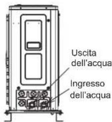
| Modello 044(2,0 HP) 080(3,0 HP) | |
| Volume minimo d'acqua richiesto 30 L 45 L |
bar
| Time (s) | 1 | 2 | 3 | 4 | 5 | 6 | 7 | 8 | 9 | 10 | |---|---|---|---|---|---|---|---|---|---|---| | 15 | 100% | 100% | 100% | 100% | 50% | 50% | 50% | ON | ON | ON | | 30 | 100% | 100% | 100% | 100% | 10% | 10% | 10% | ON | ON | ON | | 15 | 100% | 100% | 100% | 100% | 10% | 10% | 10% | ON | ON | ON | | 30 | 100% | 100% | 100% | 100% | 10% | 10% | 10% | ON | ON | ON | | 60 | 100% | 100% | 100% | 100% | 50% | 50% | 50% | ON | ON | ON | | 60 | ON | ON | ON | ON | ON | ON | ON | ON | ON | ON | | 10 | ON | ON | ON | ON | ON | ON | ON | ON | ON | ON | | 5 | ON | ON | ON | ON | ON | ON | ON | ON | ON | ON | | 5 | ON | ON | ON | ON | ON | ON | ON | ON | ON | ON | | 10 | ON | ON | ON | ON | ON | ON | ON | ON | ON | ON | | Secondi (Ripetizione periodica di 240 secondi) - Off - Line: The chart displays a single horizontal line at 10%, indicating a constant value across all segments. The X-axis represents time in seconds, and the Y-axis represents the percentage of velocity (pompa dell'acqua) and the number of vehicles (3WVs). The legend indicates that the line is labeled 'Periodica di 240 secondi'.natural_image
Technical line drawing of a multi-chamber HVAC unit with fan blades and mounting base (no text or symbols)natural_image
Technical line drawing of a multi-chamber HVAC unit with fan blades and internal components (no text or symbols)natural_image
Technical line drawing of a large air conditioning unit with fan blades and ventilation slots (no text or symbols)natural_image
Technical line drawing of an air conditioning unit with fan blades and internal components (no text or symbols)natural_image
Technical line drawing of a computer HVAC unit showing fan, circuit board, and internal components (no text or labels)
NOTA
natural_image
Diagram of a curved pipe or duct with dashed lines indicating internal flow or movement (no text or symbols)natural_image
Diagram of a cable or wire connection with a coiled spring and connecting rod (no text or symbols)natural_image
Diagram of a curved pipe or duct with internal dashed lines and two protruding rods (no text or symbols)i NOTA
natural_image
Pure electrical circuit lines without any symbolsNastro o manicotto
M6: da 4,0 a 5,0 N·m
M8: da 9,0 a 11,0 N·m
M10: da 18,0 a 23,0 N·m
Qingdao Hisense Hitachi Air-conditioning Systems Co., Ltd.
N. 218, Qianwangang Road, Economic & Technical Development Zone, Qingdao, China
10.4 OPTIONALE INNENGERÄTE-KABEL (ZUBEHÖR)....30
natural_image
Technical line drawing of a server rack with fan and ventilation slots (no text or labels)natural_image
Front view diagram of a dual-chamber HVAC unit fan with visible blades and ventilation (no text or labels)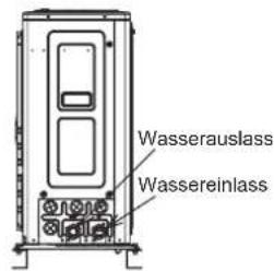
natural_image
Technical line drawing of two mechanical valve assemblies with no visible text or symbolsVORSICHT
natural_image
Technical line drawing of a multi-chamber HVAC unit with fan blades and mounting base (no text or symbols)natural_image
Technical line drawing of a multi-chamber HVAC unit with fan blades and internal components (no text or symbols)natural_image
Technical line drawing of a large air conditioning unit with fan blades and ventilation slots (no text or symbols)natural_image
Technical line drawing of an air conditioning unit with fan blades and internal components (no text or symbols)natural_image
Technical line drawing of a computer HVAC unit showing fan, ventilation chamber, and internal components (no text or labels)
HINWEIS
natural_image
Diagram of a curved mechanical component with two parallel lines, no text or symbols presentnatural_image
Technical line drawing of a mechanical clamp or bracket assembly (no text or symbols)natural_image
Diagram of a curved pipe or duct with internal dashed lines and two protruding rods (no text or symbols)
HINWEIS
Qingdao Hisense Hitachi Air-conditioning Systems Co., Ltd.
No. 218, Qianwangang Road, Economic and Technological Development Zone, Qingdao, China
Heizbetrieb
natural_image
Technical line drawing of a computer HVAC unit with fan and ventilation slots (no text or labels)Passo 2: Retire a tampa superior.

natural_image
Front view of a dual-chamber HVAC unit fan with visible blades and ventilation grille (no text or symbols)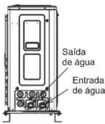
| Modelo 044 (2,0 HP) 080 (3,0 HP) | |
| Volume de água mínimo necessário | 30 L 45 L |
natural_image
Technical line drawing of a multi-chamber HVAC unit with fan blades and mounting base (no text or symbols)natural_image
Technical line drawing of a multi-chamber HVAC unit with fan blades and internal components (no text or symbols)natural_image
Technical line drawing of a large air conditioning unit with fan blades and internal components (no text or symbols)natural_image
Technical line drawing of an air conditioning unit with fan blades and internal components (no text or symbols)natural_image
Technical line drawing of a computer HVAC unit showing fan, ventilation chamber, and internal components (no text or labels)
NOTA
natural_image
Diagram of a curved mechanical component with two parallel lines, no text or symbols presentnatural_image
Technical line drawing of a mechanical clamp or bracket assembly (no text or symbols)natural_image
Diagram of a curved pipe or duct with internal dashed lines and two protruding rods (no text or symbols)
NOTA
natural_image
Pure electrical circuit lines without any symbolsFita ou manga
M10: 18,0 N·m a 23,0 N·m
| Definição de fábrica | 044 (2,0 HP) 060 (3,0 HP) | |
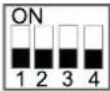 |  | |
(3) DSW3: Ajuste adicional
| Definição de fábrica | 044 (2,0 HP) 060 (3,0 HP) | |
 | 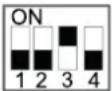 | |
4.2 VERPLAATSEN....7
5 VOOR HET EERSTE GEBRUIK....8
6 ALGEMENE AFMETINGEN 8
7 INSTALLEREN VAN DE UNIT 9
7.1 INSTALLATIERUIMTE 9
7.2 VOORZIENING INSTALLATIEPLAATS....11
7.3 AFVOERLEIDING....11
9.3 WATER BIJVULLEN....17
9.4 SELECTIE EN INSTALLATIE VAN DE WARMWATERKETEL 19
9.5 WATERCONTROLE 22
10 ELEKTRISCHE EN BESTURINGSINSTELLINGEN 23
10.4 OPTIONELE BEDRADING VAN DE BINNENUNIT (ACCESSOIRES)....30
10.5 DRAADDIAMETER EN MINIMUMEISEN VOOR DE BEVEILIGINGSVOORZIENINGEN....36
10.6 DIP-SCHAKELAARS INSTELLEN....37
11 PROEFDRAAIEN 38
11.1 CHECKLIST VÓÓR HET PROEFDRAAIEN 38
11.2 CHECKLIST TIJDENS HET PROEFDRAAIEN....39
11.3 CONTROLEER HET MINIMAAL DEBIET.... 39
12 BELANGRIJKSTE VEILIGHEIDSVOORZIENINGEN....40
13 TECHNISCHE PARAMETERS 41
1 ALGEMENE INFORMATIE
1.1 ALGEMENE OPMERKINGEN
natural_image
Technical line drawing of a server or air conditioning unit with fan and ventilation slots (no text or symbols)4 TRANSPORT, LADEN EN LOS
4.1 VERVOEREN
natural_image
Technical line drawing of a cabinet or enclosure with mounting feet and internal components, showing dimension 68 (no text or symbols present)7 INSTALLEREN VAN DE UNIT

LET OP
natural_image
Technical line drawing of two mechanical valve assemblies with no visible text or symbolsLET OP
| Model 044 (2,0 HP) 080 (3,0 HP) | |
| Minimum vereist watervolume 30 L 45 L |
Unit: H (m), Pg (bar)
- Berekening van D, (60 °C):
natural_image
Technical line drawing of a multi-chamber HVAC unit with fan blades and mounting base (no text or symbols)natural_image
Technical line drawing of a multi-chamber HVAC unit with fan blades and internal components (no text or symbols)natural_image
Technical line drawing of a large air conditioning unit with fan blades and ventilation slots (no text or symbols)natural_image
Technical line drawing of an air conditioning unit with fan blades and internal components (no text or symbols)natural_image
Technical line drawing of a computer HVAC unit showing fan, ventilation chamber, and internal components (no text or labels)
OPMERKING
natural_image
Diagram of a curved pipe or tube with dashed lines indicating internal structure (no text or symbols)natural_image
Technical line drawing of a mechanical clamp or bracket assembly (no text or symbols)natural_image
Diagram of a flexible cable or wire with dashed and solid lines indicating internal components (no text or symbols)
OPMERKING
natural_image
Pure electrical circuit lines without any symbolsTape of mof
| Fabrieksinstelling | 044 (2,0 HP) 080 (3,0 HP) | |
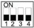 |  | |
(3) DSW3: Aanvullende instelling
| Fabrieksinstelling | 044 (2,0 HP) 060 (3,0 HP) | |
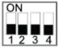 | 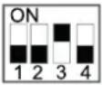 | |
(3) DSW6: Koelsysteemnummer instellen Deze instelling is vereist Gebruik binaire coderingsmethode.
| Fabrieksinstelling | 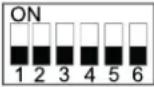 |
Qingdao Hisense Hitachi Air-conditioning Systems Co., Ltd. No. 218, Qianwangang Road, Economic and Technological Development Zone, Qingdao, China
natural_image
Technical line drawing of a server rack with fan and ventilation slots (no text or labels)natural_image
Technical line drawing of a rectangular mechanical component with internal channels and an upward arrow indicator (no text or symbols)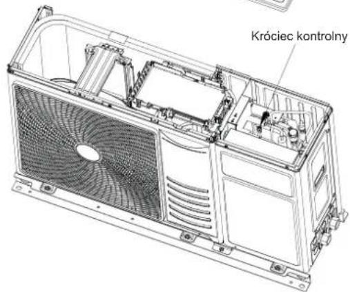
natural_image
Technical line drawing of two mechanical valve assemblies with no visible text or symbolsOSTROŻNIE
natural_image
Technical line drawing of a multi-chamber HVAC unit with fan blades and mounting base (no text or symbols)natural_image
Technical line drawing of a multi-chamber HVAC unit with fan blades and internal components (no text or symbols)natural_image
Technical line drawing of a large air conditioning unit with fan blades and ventilation slots (no text or symbols)natural_image
Technical line drawing of an air conditioning unit with fan blades and internal components (no text or symbols)natural_image
Technical line drawing of an internal air conditioning unit with fan blades and internal circuitry (no text or labels)
UWAGA
natural_image
Pure diagram of a curved mechanical component with a straight line, no text or symbols presentnatural_image
Diagram of a curved mechanical component with two parallel lines and a dashed line, no text or symbols present.natural_image
Technical line drawing of a mechanical clamp or bracket assembly (no text or symbols)natural_image
Diagram of a flexible cable or wire with dashed internal bands and connecting wires (no text or symbols)
UWAGA
natural_image
Pure electrical circuit lines without any symbolsTašma lub tulėjka
1.2 GENEL GÜVENLIK 1
2 GÜVENLIK....4
2.1 KULLANILAN SEMBOLLER....4
2.2 GÜVENLIK HAKKINDA ILAVE BILGILER 4
3 ÖNEMLI NOT 5
3.1 BILGI 5
3.2 MINIMUM ZEMIN ALANI GEREKLILIKLERI 6
3.3 KONTROL EK YERINDEKI BASINCA DIKKAT EDIN....7
4 TAŞIMA VE İŞLEMLER....7
4.1 TAŞIMA....7
4.2 ELLEÇLEME....7
5 KULLANIMDAN ÖNCE 8
6 GENEL BOYUTLAR 8
7 ÜNITE KURULUMU 9
7.1 KURULUM ALANI 9
7.2 KURULUM YERININ TEMINI 11
7.3 TAHLIYE BORULARI 11
7.4 SU BORULARI....12
8 SOĞUTUCU MADDE DEVRESI....13
8.1 SOĞUTUCU MADDE DOLUMU....13
8.2 SOĞUTUCU MADDE SIZINTISINDA ALINACAK ÖNLEMLER.... 13
(EQU.1)
A_min = (m_c / (2,5^*LFL^(5 / 4) * h_0)^ 2
natural_image
Technical line drawing of a server rack with fan and ventilation slots (no text or labels)natural_image
Technical line drawing of two mechanical valve assemblies with no visible text or symbols⚠️ DİKKAT
Ünite: H (m), Pg (bar)
natural_image
Technical line drawing of a multi-chamber HVAC unit with fan blades and mounting brackets (no text or symbols)natural_image
Technical line drawing of a multi-chamber HVAC unit with fan blades and internal components (no text or symbols)natural_image
Technical line drawing of a large air conditioning unit with fan blades and ventilation slots (no text or symbols)natural_image
Technical line drawing of an air conditioning unit with fan blades and internal components (no text or symbols)natural_image
Technical line drawing of a computer HVAC unit showing fan, ventilation chamber, and internal components (no text or labels)
NOT
natural_image
Diagram of a curved mechanical component with two parallel lines, no text or symbols presentnatural_image
Pure mechanical diagram of a coiled spring or clamp assembly without any text, numbers, or symbolsnatural_image
Diagram of a flexible cable or wire with dashed internal lines and two connectors (no text or symbols)i NOT
natural_image
Pure electrical circuit lines without any symbolsBant veya manşon
M8: 9,0 ila 11,0 N·m
M10: 18,0 ila 23,0 N·m
1.2 SIGURANTĂ GENERALĂ....1
2 SIGURANTĂ....4
2.1 SIMBOLURI FOLOSITE....4
2.2 INFORMATII SUPLIMENTARE DESPRE SIGURANTĂ....4
3 OBSERVATIE IMPORTANTĂ .... 5
3.1 INFORMATIE 5
3.2 CERINȚE MINIME DE SPATIU 6
3.3 ATENTIE LA PRESIUNE LA PRIZA DE PRESIUNE....7
4 TRANSPORT ŞI MANIPULARE ....7
4.1 TRANSPORT 7
4.2 MANIPULARE 7
5 ÎNAINTE DE OPERARE 8
6 DIMENSIUNI GENERALE 8
7 INSTALAREA UNITĂȚII....9
7.1 SPAȚIU DE INSTALARE....9
7.2 CERINTE PRIVIND LOCUL DE INSTALARE....11
7.3 CONDUCTELE DE DRENAJ....11
7.4 CONDUCTA DE APĂ....12
8 CIRCUITUL DE AGENT FRIGORIFIC 13
8.1 UMPLEREA CU AGENT FRIGORIFIC 13
8.2 PRECAUTII ÎN CAZUL SCURGERII DE AGENT FRIGORIFIC.... 13
9 ÎNCĂLZIRE ȘI APĂ CALDĂ MENAJERĂ....13
9.1 COMPONENTE HIDRAULICE SUPLIMENTARE NECESARE 13
9.2 CERINTE ŞI RECOMANDĂRI PENTRU CIRCUITUL HIDRAULIC 15
9.3 UMPLEREA CU APĂ....17
9.4 SELECTAREA ŞI INSTALAREA REZERVORULUI DE ACM....19
9.5 CONTROLUL APEI....22
10 SETĂRI ELECTRICE ȘI DE CONTROL ....23
10.1 VERIFICĂRI GENERALE 23
10.2 CONECTAREA CABLAJULUI ELECTRIC AL UNITĂȚILOR EXTERIOARE 24
10.3 CONEXIUNILE TABLOULUI DE BORNE 27
10.4 CABLAJ OPTIONAL PENTRU UNITATEA INTERIOARĂ (ACCESORII)....30
10.5 DIMENSIUNILE CABLURILOR ŞI CERINTELE MINIME PENTRU DISPOZITIVELE DE PROTECTIE ..... 36
10.6 SETAREA COMUTATOARELOR DIP 37
11 PROBĂ DE FUNCȚIONARE 38
11.1 LISTĂ DE VERIFICĂRI ÎNAINTE DE EFECTUAREA PROBEI....38
11.2 LISTĂ DE VERIFICĂRI ÎN TIMPUL EFECTUĂRII PROBEI 39
11.3 VERIFICAREA DEBITULUI MINIM 39
12 PRINCIPALELE DISPOZITIVE DE SIGURANTĂ....40
13 PARAMETRI TEHNICI....41
1 INFORMATII GENERALE
1.1 OBSERVATII GENERALE
1.2 SIGURANTĂ GENERALĂ
natural_image
Technical line drawing of a server rack with fan and ventilation slots (no text or symbols)natural_image
Technical line drawing of a cabinet or enclosure with mounting holes and a vertical dimension labeled 68 (no text or symbols beyond measurement lines)7 INSTALAREA UNITĂȚII

PRECAUTIE
natural_image
Technical line drawing of two mechanical components with arrows indicating motion (no text or symbols)PRECAUTIE
- Calcularea D _i (60 °C):
natural_image
Technical line drawing of a multi-chamber HVAC unit with fan blades and mounting base (no text or symbols)natural_image
Technical line drawing of a multi-chamber HVAC unit with fan blades and internal components (no text or symbols)natural_image
Technical line drawing of a large air conditioning unit with fan blades and ventilation slots (no text or symbols)natural_image
Technical line drawing of an air conditioning unit with fan blades and internal components (no text or symbols)Pasul 5: Efectuati cablajul.

natural_image
Technical line drawing of a computer HVAC unit showing fan, ventilation chamber, and internal components (no text or labels)
NOTĂ

PRECAUTIE
natural_image
Diagram of a curved pipe or tube with dashed lines indicating internal structure (no text or symbols)natural_image
Pure mechanical diagram of a coiled spring or clamp assembly without any text, numbers, or symbolsnatural_image
Diagram of a curved mechanical component with internal dashed lines and fasteners, no text or symbols presenti NOTĂ
natural_image
Pure electrical circuit lines without any symbolsBandă sau manşon
M10: 18,0 - 23,0 N·m
| Setare din fabrică | 044 (2,0 CP) 080 (3,0 CP) | |
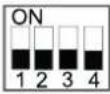 |  | |
| Setare din fabrică | 044 (2,0 CP) 080 (3,0 CP) | |
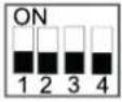 | 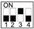 | |
Qingdao Hisense Hitachi Air-conditioning Systems Co., Ltd.
No. 218, Qianwangang Road, Economic and Technological Development Zone, Qingdao, China
Add.: No. 218, Qianwangang Road, Economic and Technological Development Zone, Qingdao, China
http://www.hisense-vrf.com E-mail: export@hisensehitachi.com
The Company is committed to continuous product improvement. We reserve the right, therefore, to alter the product information at any time and without prior announcement.