
YT-82462 - Welding machine Yato - Free user manual and instructions
Find the device manual for free YT-82462 Yato in PDF.

| Product type | Soldering station with temperature control |
| Brand | Yato |
| Model | YT-82462 |
| Rated voltage | 110-240 V~, 50-60 Hz |
| Rated power | 75 W |
| Iron supply voltage | 24 V DC |
| Temperature range | 90 °C to 480 °C |
| Temperature stability | ±2 °C |
| Weight | 0.47 kg |
| Fuse | 6 A / 250 V, type F6AL250V |
| Insulation class | 1 |
| Tip-to-ground resistance | < 2 Ω |
| Tip-to-ground voltage | < 2 mV |
| Programmable temperature memories | 3 (CH1, CH2, CH3) |
| Standby timer | 20-999 seconds adjustable |
| Temperature units | °C or °F (switchable) |
| Temperature calibration | Yes, range -80 °C to +80 °C |
| Included accessories | Stand, sponge, protective cap, interchangeable tips |
| Operating conditions | 0 °C to +40 °C, relative humidity < 70 % |
| Maintenance | Clean the tip with a damp sponge; replace the sponge if worn |
Frequently Asked Questions - YT-82462 Yato
User questions about YT-82462 Yato
0 question about this device. Answer the ones you know or ask your own.
Ask a new question about this device
Download the instructions for your Welding machine in PDF format for free! Find your manual YT-82462 - Yato and take your electronic device back in hand. On this page are published all the documents necessary for the use of your device. YT-82462 by Yato.
USER MANUAL YT-82462 Yato
natural_image
Exterior view of a YATO printer and soldering terminal (no text or symbols on main components)CE
PL EN DE RU UA LT LV CZ SK HU RO ES FR IT NL GR BG PT HR AR
natural_image
Two black-and-white photos showing a hand holding a screwdriver, with no visible text or symbols.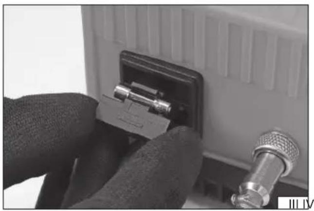
natural_image
Close-up of hands installing a connector into a device component (no visible text or symbols)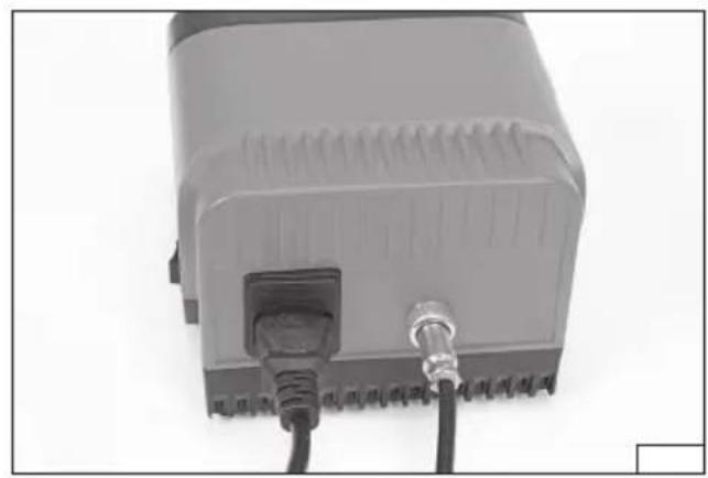
natural_image
Close-up of a gray electronic device with two cables and connectors (no visible text or symbols)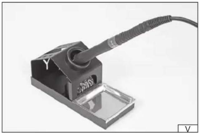
natural_image
Close-up of a soldering iron component with a coiled cable and a labeled Y mark, no readable text or symbols beyond the label.
natural_image
Electronic soldering kit and XATO device on a plain background (no visible text or symbols)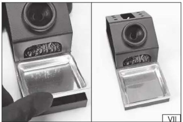
natural_image
Two views of a small electronic device with a hand inserting a transparent container into its side (no visible text or symbols)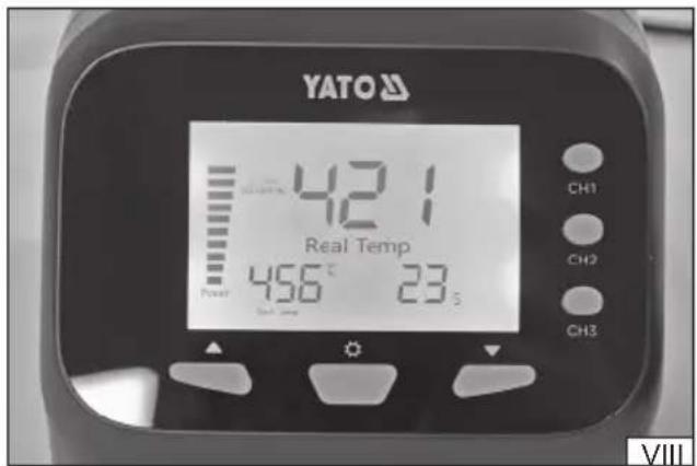
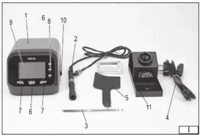
- soldering station
- soldering iron
- tip
- power cord
- protective cap
- heating
- function
- programming
- display
- power switch
- soldering iron stand
DE
Read the operating instruction
Wear protective goggles
This symbol indicates that waste electrical and electronic equipment (including batteries and storage cells) cannot be disposed of with other types of waste. Waste equipment should be collected and handed over separately to a collection point for recycling and recovery, in order to reduce the amount of waste and the use of natural resources. Uncontrolled release of hazardous components contained in electrical and electronic equipment may pose a risk to human health and have adverse effects for the environment. The household plays an important role in contributing to reuse and recovery, including recycling of waste equipment. For more information about the appropriate recycling methods, contact your local authority or retailer.
CHARAKTERYSTYKA WYROBU
PRODUCT CHARACTERISTICS
The soldering station is an electrical tool intended for soldering, binding through soldering of metal materials using zinc-lead and lead-free solders for soft soldering. Thanks to the interchangeable tips and temperature adjustment, it is possible to solder fine electrical and electronic components without the risk of overheating. Product is not designed for commercial use. The correct, reliable, and safe operation of the tool depends on its proper use, therefore:
Read the entire manual before the first use of the tool, and keep it for future reference.
The supplier is not liable for any damage resulting from failure to observe the safety instructions and recommendations contained in this manual.
COMPONENTS
The soldering stations are supplied complete, but require assembly as described later in this manual before first use.
TECHNICAL DATA
| Parameter Unit Value | ||
| Part No. YT-82462 | ||
| Rated voltage [V~] 110 – 240 | ||
| Rated frequency [Hz] 50 – 60 | ||
| Rated power [W] 75 | ||
| Soldering iron supply voltage [VDC] 24 | ||
| Tip temperature | [°C] | 90 – 480 |
| Temperature stability | [°C] +/- 2 | |
| Insulation class | 1 | |
| Weight | [kg] | 0.47 |
| Tip-to-ground resistance | [Ω] | <2 |
| Tip-to-ground voltage | [mV] | <2 |
| Fuse | 6 A / 250 V, F6AL250V type |
SAFETY INSTRUCTIONS
Irresponsible use of the equipment can cause fire, therefore exercise caution when using the equipment in areas where combustible materials are present; do not direct a stream of hot air at the same spot or place the soldering iron tip to the same spot for an extended period; do not use the equipment in an explosive atmosphere; be aware that heat may be transferred to combustible materials out of sight; place the equipment on its stand after use and leave it to cool down before storage; do not leave the equipment unattended when switched on.
Before starting work, make sure that the housing and the power cord and plug are not damaged. In case of damage, do not proceed with work.
This tool must not be used by children. Children should not play with the tool. Children left unattended should not be allowed to perform the cleaning and maintenance of the tool. This tool may not be used by persons with reduced physical, mental abilities and persons with no experience or knowledge of the tool, if supervised or instructed on its safe use so that the risks associated with it are understood.
The tool is not designed to operate in high humidity conditions. The temperature at the place of the tool's use must be within the range of 0^ ÷ +40^ , and the relative humidity must be below 70% without condensation. Do not expose the tool to precipitation.
Before connecting the tool to the power supply, make sure that the voltage, frequency and performance of the mains correspond to the values shown on the tool's rating plate. The plug
EN
must fit into the socket. It is forbidden to modify the plug or socket in any manner to make them fit. The tool must be connected directly to a single power supply socket. It is forbidden to use extension cords, adapters or double sockets. The supply network circuit must be equipped with a 16 A protection. Avoid contact of the power cord with sharp edges and hot objects and surfaces. During operation, the power cord must always be fully extended and the position of the power cord must be set so that it does not become an obstacle during operation. The power cord should not be placed in a manner which would pose a risk of tripping. The mains socket should be located in a place where it is always possible to quickly remove the tool's power cord plug. Always pull the power cord by the plug housing when unplugging it, never by the cord. If the power cord or the plug is damaged, immediately disconnect it from the mains and contact an authorised service centre of the manufacturer for replacement. Do not use the product with a damaged power cord or plug. The power cord or plug cannot be repaired and must be replaced with a new one that is free of defects if these components are damaged.
WARNING! The metal components of the tool can be hot during and immediately after use. Do not touch them, as it may cause severe burns. Allow the tool components to cool down. Use gloves which protect against high temperatures if you need to move these components before they cool down. Make sure that the floor near the place of use of the tool is not slippery. This will prevent slipping, which can cause serious injuries. Never block or restrict the throughput of the ventilation openings. Do not use the tool in the bathroom or near water. Do not touch the tip as this can cause burns. After use, allow the tool to cool down before storing it. Do not accelerate the process of self-cooling of the tool components in any manner.
NOTE! Only install the equipment when the supply voltage is disconnected. Pull the tool power cord plug out of the mains socket! Make sure that all components have cooled down before assembling and disassembling the tool. Before starting assembly, make sure that the soldering station power switch is in the "off" position – O.
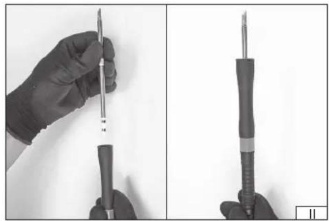
Tip installation/replacement
Select a suitable tip and insert it into the soldering iron bore as shown in photo (II). The tip end should be outside of the soldering iron.
NOTE! Take special care when replacing the tip. The soldering iron tip can be hot during use and immediately after use. Do not touch the tip as this may cause severe burns. It is recommended to wait until the soldering iron tip and components have cooled completely. Do not accelerate the process of self-cooling of the tool components in any manner. Always wear heat protective gloves and use the supplied protective cap to assist with tip replacement if it becomes necessary to replace the tip before it has cooled down. Allow the tip to cool down completely by placing it in one of the holes on the back of the soldering iron stand.
Fuse replacement (III)
The soldering station power cord must be disconnected from the tool. A pull-out cap is located in the power socket in which the fuse and a spare fuse are located. To replace the fuse, carefully remove the cap so as not to damage the power socket. Replace the fuse. The fuse parameters can be found in the technical data table. It is forbidden to use a fuse other than those specified in the technical data table. Slide the cap into place.
Installation of accessories
Connect the soldering iron cord to the port at the back of the soldering station housing (IV). The plug has such a shape that it can be connected in one correct way only. Secure the connection by screwing a metal plug ring on the thread around the port in the soldering station housing.
Place the soldering iron on the stand (V).
Connect the power cord to the port at the back of the housing. The plug has such a shape that it can be inserted in one correct way only (IV).
EN
Position the station at the workplace, e.g., on the table to ensure easy access to the controls and that no objects cover the display (VI). Place the soldering iron stand near the station to ensure free access to the soldering iron and prevent the soldering iron tip from unintentional coming into contact with any object during operation, storage on the stand, and movement of the soldering iron during operation. Due to the high temperature of the tip, leave at least 10 cm of free space around the stand. The stand should be placed on a heat-resistant surface. There is a special opening in the base where brass shavings for cleaning the tip can be placed. Place the base recess in the base housing (VII). The sponge intended for cleaning the tip during operation should be placed in the base recess. The sponge should be damp but not wet during the entire operation period. This will prevent the tip damage. Only after setting up the station and the stand and performing a trial operation can the station be connected to the power supply.
Switching the tool on and off
The tool is started by turning the power switch to the “on” position – I. The tool’s display will be illuminated and “OFF” message will be displayed. This means that the station’s power is on and it is in standby mode. To switch the soldering station on and activate the heating, press and hold the heating button for approx. 1.5 seconds. A single sound signal is emitted when the heating process starts. The station will switch to operating mode and start heating. Press and hold the heating button for approx. 1.5 seconds to turn off heating and switch to standby mode. If it is necessary to switch the tool off entirely, flip the power switch to the “off” position – O.
Parameter setting
Parameter setting is carried out using the function buttons. The button marked with an arrow pointing up is used to increase the parameter value and the button marked with an arrow pointing down is used to decrease the parameter value. A sound signal is emitted when the parameter value is changed.
Display (VIII)
The following parameters are shown on the display when the soldering station is in operation:
"Real Temp" – the value in the centre of the display indicates the actual tip temperature.
"Set Temp" – the value at the bottom left of the display indicates the set temperature to which the tip is to be heated.
"Power" – the value on the left side of the display indicates the timed heating power level.
Sleep mode time – the value at the bottom right of the display indicates the time remaining until the station enters sleep mode.
Timed sleep mode setting
The soldering station has a sleep mode function which switches on after pre-set time has elapsed. Changes to the sleep mode time length must be made in standby mode. Switch on the soldering station by flipping the power switch to the "on" position – I, then simultaneously press and hold the function buttons marked with the arrow pointing up and arrow pointing down until the time indicated in seconds is displayed. Use the function buttons to set the time length between 20 and 999 seconds. The length of time is automatically saved and the station returns to standby mode once the time is set and the selection button is released. In operation mode, the soldering station will enter sleep mode after the set time has elapsed only when the soldering iron is not in use. Bringing the tool out of sleep mode is done by lifting the soldering iron from the stand or by briefly pressing one of the function buttons. It is also possible to bring the soldering iron out of sleep mode by pressing one of the programming buttons – CH1, CH2 or CH3. In this case, heating to the temperature previously saved under the selected button will begin.
Temperature setting
To set the tip temperature, turn the soldering station on by flipping the power switch to the "on" position – I, then press and hold the heating button for approx. 1.5 seconds. The station will switch to operation mode and temperature adjustment will be enabled. The tip temperature can be set between 90^ and 480^ using the function buttons marked with an arrow pointing up or arrow pointing down. The value is automatically saved once setting is complete.
Temperature programming
The station can store three different temperature settings. First, set the temperature and then press and hold one of the temperature programming buttons – CH1, CH2 or CH3. The symbol of the selected setting will flash on the display. The value is automatically saved once setting is complete. The value programmed under the CH1 button is the default temperature value. This means that when the station is restarted, the soldering iron tip will heat up to the pre-set temperature.
Changing the temperature unit
Changing the temperature unit is possible in the soldering station operating mode by quickly pressing the heating button twice. The ^ C symbol displayed next to the set temperature indicates degrees Celsius, and the ^ F symbol indicates degrees Fahrenheit. The value is automatically saved once setting is complete.
Temperature calibration
The tip is equipped with a heater, the parameters of which can be subject to change during use. Thanks to calibration, the temperature set for the soldering station will correspond to the actual tip temperature. The temperature should be measured with an external thermometer, such as a thermocouple connected to a multimeter. The displayed value should then be adjusted to equal
EN
the measured value.
To enter the temperature calibration mode, turn the soldering station on by flipping the power switch to the "on" position - 1, then press and hold the heating button for approx. 1.5 seconds. Temperature can be calibrated when the station starts working and reaches a pre-set temperature. Simultaneously press and hold the function buttons marked with an arrow pointing up and an arrow pointing down to display the temperature calibration value in the -80^ +80^ range. Use the function button marked with an arrow pointing up or an arrow pointing down to select the appropriate value. The value is automatically saved once setting is complete.
MAINTENANCE AND STORAGE
After finishing work, clean the tip using a damp sponge and then place the soldering iron in the stand, turn off the soldering station with the power switch and leave it until all elements have cooled down completely. Disconnect the station from the power supply by pulling the power cord plug out of the mains socket. Clean the station housing and soldering iron holder with a soft cloth slightly dampened with water, then dry it.
Check the tip condition; if any defects, damage, or changes in shape are found, replace the tip with a new one. The sponge for cleaning the tip should be cleaned under a jet of lukewarm water. Replace excessively dirtied or damaged sponges with new ones. Store the product disconnected from the power supply in places not accessible to unauthorised persons, especially children. The storage place should protect against dust, moisture, precipitation and excessive heat, and provide adequate ventilation to prevent condensation of water vapour.

