
Datalink Pro - Video transceiver DJI - Free user manual and instructions
Find the device manual for free Datalink Pro DJI in PDF.

| Product Type | Video Transceiver |
| Brand | DJI |
| Model | Datalink Pro (400 and 900 variants) |
| Dimensions (without antenna) | Base station: 82.9 × 51 × 14.35 mm; Mobile station: 57.8 × 42.3 × 9.35 mm |
| Weight (without antenna) | Base station: 53 g; Mobile station: 25.5 g |
| Power Supply | 9 V DC |
| Power Consumption | Base station: 2.1 W (400) / 1.2 W (900); Mobile station: 0.65 W |
| Operating Temperature | 0 to 45 °C |
| Storage Temperature | -40 to 85 °C |
| Humidity | 5 to 95% without condensation |
| Frequency Bands | DATALINK PRO 400: 430-432 MHz (China), 429.175-429.2375 MHz (Taiwan), 447.8625-447.9875 MHz (Korea); DATALINK PRO 900: 869.525 MHz (CE), 903-925.5 MHz (FCC/Canada/Australia), 923.1-926.3 MHz (Japan) |
| Transmission Distance | DATALINK PRO 400: up to 1000 m (depending on region); DATALINK PRO 900: up to 2000 m (depending on region) |
| Transmission Power | DATALINK PRO 400: 10 dBm (China, Taiwan, Korea); DATALINK PRO 900: 27 dBm (FCC/Canada/Australia), 13 dBm (CE), 10 dBm (Japan) |
| Serial Data Rate | 15200 bit/s |
| Interfaces | USB, UART, CAN |
| Max Number of Mobile Stations | Full Duplex Mode: 1; Broadcast Mode: 32 |
| Compatible Products | A3, D-RTK |
| Main Functions | Real-time wireless data transmission, point-to-point or multipoint communication, pairing, configuration via DJI Assistant 2 |
| Safety | Use in an open environment without radio interference; use only official DJI parts; avoid water, oil, dirt, and sand |
| Maintenance and Cleaning | Protect from contamination; clean with a dry cloth |
| Spare Parts and Repairability | Official DJI parts; firmware update via DJI Assistant 2 |
| General Information | Compliant with European directive 2014/53/EU; Industry Canada certification; license-exempt |
Frequently Asked Questions - Datalink Pro DJI
User questions about Datalink Pro DJI
0 question about this device. Answer the ones you know or ask your own.
Ask a new question about this device
Download the instructions for your Video transceiver in PDF format for free! Find your manual Datalink Pro - DJI and take your electronic device back in hand. On this page are published all the documents necessary for the use of your device. Datalink Pro by DJI.
USER MANUAL Datalink Pro DJI
natural_image
Line drawing of a white DATALINE electronic device with ports and indicator lights (no text or symbols on body)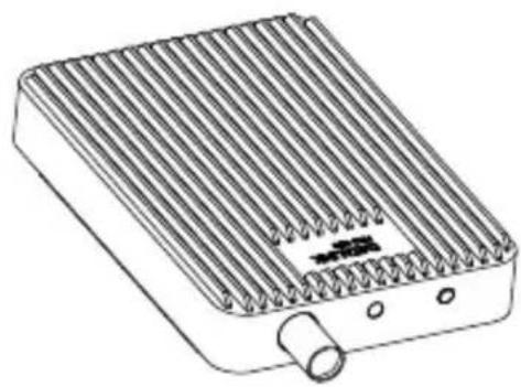
natural_image
Line drawing of a heat exchanger or radiator unit with cooling fins and a cylindrical outlet (no text or symbols)
Important notes are indicated by this symbol.
重要注意事项说明符号
重要備註說明符號。
この記号は、重要な注意事項を表します。
Download the latest version from
您可以在 DJI 官方网站查询最新版本
您可至下列網址下載最新版本
Thank you for purchasing the DATALINK PRO (hereinafter referred to as "product"). Read this disclaimer carefully before using this product. By using this product, you hereby agree to this disclaimer and signify that you have read it fully. Please install and use this product in strict accordance with this manual. SZ DJI Technology Co., Ltd. and its affiliated companies assume no liability for damage(s) or injuries incurred directly or indirectly from using, installing or refitting this product improperly, including but not limited to using non-designated accessories.
DJI ^™ is a trademark of SZ DJI Technology Co., Ltd. (abbreviated as “DJI”) and its affiliated companies. Names of products, brands, etc., appearing in this manual are trademarks or registered trademarks of their respective owner companies.
This product and manual are copyrighted by DJI with all rights reserved. No part of this product or manual shall be reproduced in any form without the prior written consent of or authorization from DJI.
This disclaimer is produced in various languages. In the event of variance among different versions, the Simplified Chinese version shall prevail when the product in question is purchased in Mainland China, and the English version shall prevail when the product in question is purchased in any other region.
Warnings
- Only use the DATALINK PRO in the corresponding frequency band and in accordance with local laws and regulations.
- Ensure all modules are connected and the parameters are set correctly in DJI Assistant 2 when using the DATALINK PRO for the first time.
- DO NOT bend or fold the antennas excessively.
- Ensure the antennas for both the Mobile Device and the Base Station are unobstructed when used.
- Only use the DATALINK PRO in an open environment free from radio interference.
- Only pair the DATALINK PRO Base Station with a Mobile Station in the same frequency band. Note that the DATALINK PRO 400 and DATALINK PRO 900 are not compatible.
- When upgrading the firmware, toggle the 4-position switch to the COMBO_SW4 position, connect the module to the PC, and then run DJI Assistant 2.
- To avoid interference, DO NOT use a two-way transceiver or walkie-talkie operating near the 400 MHz band when operating the DATALINK PRO 400.
- Only use genuine DJI parts or parts certified by DJI. Unauthorized parts or parts from non-DJI-certified manufacturers may cause system malfunctions and compromise safety.
- Ensure the DATALINK PRO and its components are free from contamination (e.g. water, oil, soil and sand).
- Download the latest version of the user manual or software for any related DJI product that is required when using this product.
Introduction
The DATALINK PRO is used for real-time wireless data transmission, including communication between the Base Station and the Mobile Station. There are DATALINK PRO 400 and DATALINK PRO 900 versions to meet the requirements of different regions. The multi-functional bidirectional transmission link is perfect for the DJI A3 flight control system and D-RTK. Use frequency bands near 400 MHz and 900 MHz to avoid radio interference with the DJI Lightbridge and remote controller. Support for multiple interfaces, such as USB, CAN and UART, offers additional connectivity.
E Z
Overview
Base Station
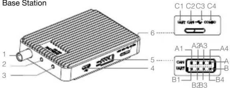
- Antenna Interface
- Working Status Indicator
- Linking Button
- Micro USB
- CAN/UART Port, CAN port and UART port can be used separately.
A. CAN port with baud rate of 1 Mbps.
A1: Power (DC 9 V input)
A2: GND
A3: CAN-H
A4: CAN-L
B. UART port with baud rate 115200 bps supported.
B1: Power (DC 9 V input)
B2: GND
B3: UART-RX
B4: UART-TX
- 4-position Switch
C1: UART_SW1
C2: CAN_SW2
C3: USB_SW3
C4: COMBO_SW4
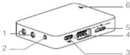
Mobile Station
Base Station Antenna*
or
- Antenna Interface
- Linking Button
- Micro USB
- CAN/UART Port (same specification as the Base Station)
- 4-position Switch (same specification as the Base Station)
- Working Status Indicator
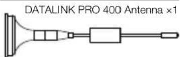
DATALINK PRO 900 Antenna ×1

Mobile Station Antenna *
DATALINK PRO 400 Antenna ×3 DATALINK PRO 900 Antenna ×3


Accessories

Micro USB Cable ×1
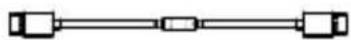
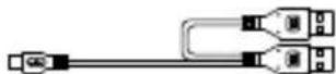

4-pin Cable ×1

* The DATALINK PRO 400 and DATALINK PRO 900 use different antennas with identical functionality. No need to install antennas for the TAIWAN version as the antennas are built-in.
Installation and Connection
The following uses the DATALINK PRO 900, DJI Matrice 600, D-RTK and DJI Intelligent Flight Battery to illustrate a typical installation and connection.
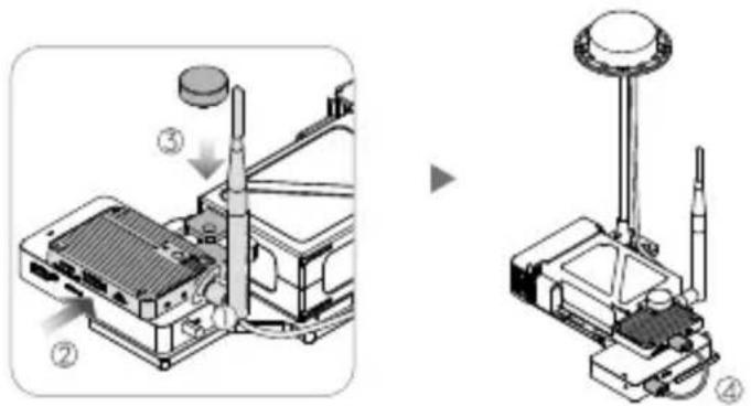
- Attach the Base Station antenna. Place the Base Station on the D-RTK Ground System's base board, and then fix it with a screw (included with the D-RTK product). Then connect the Base Station and the D-RTK Ground System via an 8-pin cable.
E
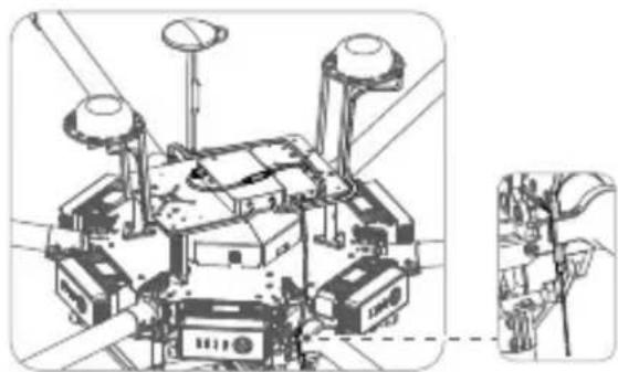
- Install the Mobile Station to the DJI Matrice 600 with double-sided tape. Attach the antennas to the Mobile Station and fix them to the frame arms with two clips. Then connect the Mobile Station and the D-RTK Air System via an 8-pin cable.
natural_image
Technical line drawing of a mechanical assembly with no visible text or symbols
- Refer to the "D-RTK User Manual" for details if using the D-RTK.
Usage
Use the DATALINK PRO in an open environment free from radio interference. The DATALINK PRO can work in Full Duplex Mode and Broadcast Mode as described below:
- Full Duplex Mode: Toggle the 4-position switch to the UART_SW1, CAN_SW2 or USB_SW3 position. This is useful for point-to-point communications.
- Broadcast Mode: Toggle the 4-position switch to the UART_SW1, CAN_SW2 or USB_SW3 position. This is useful for point to multi-point (up to 32) transmissions.

• Full Duplex Mode and Broadcast Mode can be turned on or off in DJI Assistant 2.
- Be sure to toggle the 4-position switch to the UART_SW1 position if using the D-RTK and working in Full Duplex Mode or Broadcast Mode, otherwise the D-RTK may fail to receive data from the DATALINK PRO.
Linking Procedures
The Base Station and Mobile Station come already linked out of the box. Note that frequency linking is required if any device is changed or added.
- Enable the D-RTK Ground System's battery to power on the DATALINK PRO Base Station.
- Hold the Base Station's Linking Button for about 3 seconds to enter Linking mode. The Working Status LED will blink red and green alternatively.
- Enable the D-RTK Ground System's battery to power on the DATALINK PRO Mobile Station.
- Hold the Mobile Station's Linking Button for about 3 seconds and wait for linking.
- The Base Station and Mobile Station will exit Linking mode and connect with each other if successfully linked.
- Follow linking procedures 2-5 to link other Mobile Stations one by one when setting up a single-to-multiple system.
Configuring Parameters with DJI Assistant 2
- Download DJI Assistant 2 from www.dji.com and install it on your computer.
- Toggle the 4-position switch to the COMBO_SW4 position, connect the Base Station to the computer with DJI Assistant 2 running, and then configure parameters according to the message prompts.
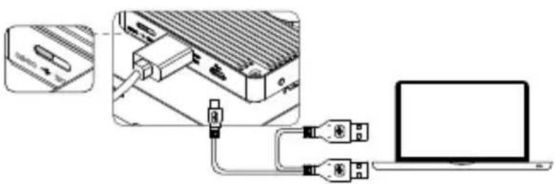
natural_image
Diagram showing connection between a device and a laptop via USB cable (no text or symbols present)- Configure the Mobile Station in the same way. If multiple Mobile Stations are used, you must configure each Mobile Station one by one.

natural_image
Diagram showing a mechanical assembly connected to a laptop via cable and connector (no text or symbols present)
- Power cycle the DATALINK PRO, Flight Control System and D-RTK after upgrading.
- DJI Assistant 2 supports Windows 7 (or later) or Mac OS X 10.9 (or later).
| LED Description | ||
| W — | Solid White | Device is initializing, only displays when powering on. |
| R — | Solid Red | Base Station: All Mobile Stations are disconnected in Full Duplex Mode.Mobile Station: All Mobile Stations are disconnected in both Full Duplex Mode and Broadcast Mode. |
| G — | Solid Green | Base Station: At least one Mobile Station connected to the Base Station in Full Duplex Mode.Mobile Station: Mobile Station connected correctly in Full Duplex Mode. |
| B — | Solid Blue | Base Station: Working in Broadcast Mode.Mobile Station: Working in Broadcast Mode and receiving the data from Base Station. |
| R G ...... | Blinking Red and Green Alternately | Linking in progress. |
| P ...... | Blinking Purple Connected to the Assistant successfully. | |
| Y ...... | Blinking Yellow Upgrading or preparing for upgrade. | |
| Y Y | Blinking Yellow Twice | 4-position switch is toggled successfully. |
| G ...... | Quickly Blinking Green | Current system setting is saved (Run mode changed successfully), or connected device information is clear. |
| R ...... | Blinking Red | Parameter error after powering on. If not resolved by power cycling, contact your dealer. |
Specifications
| Type DATALINK PRO 400 DATALINK PRO 900 | ||
| Performance | ||
| Transmission Power | Mainland China:10dBmTaiwan, China:10dBmSouth Korea:10dBm | CE: 13dBmFCC: 27dBmCanada: 27dBmAustralia: 27dBmJapan: 10dBm |
| Transmission distance | Mainland China:600 mTaiwan, China:1000 mSouth Korea:1000 m | CE: 300 mFCC: 2000 mCanada: 2000 mAustralia: 2000 mJapan: 1200 m |
| Power Consumption | Base Station:2.1 WMobile Station:0.65 W | Base Station:1.2 WMobile Station:0.65 W |
| Features | ||
| Frequency Band (MHz) | Mainland China:430-432Taiwan, China:429.175-429.2375South Korea:447.8625-447.9875 | CE: 869.525FCC: 903-925.5Canada: 903-925.5Australia: 916.5-925.5Japan: 923.1-926.3 |
| Serial Data Rate 115200 bps | ||
| Antenna Options Vertically polarized | ||
| Supported Interfaces USB, UART, CAN | ||
| Supported Max. Mobile Station Number | Full Duplex Mode: 1Broadcast Mode: 32 | |
| Supported DJI Products | A3, D-RTK | |
| Operating Temperature | 32° to 113°F (0° to 45°C) | |
| Storage Temperature -40° to 185°F (-40° to 85°C) | ||
| Humidity 5% to 95%, non-condensing | ||
| Dimension (without Antenna) | Base Station:82.9 mm × 51 mm × 14.35 mmMobile Station:57.8 mm × 42.3 mm × 9.35 mm | |
| Weight (without Antenna) | Base Station: 53 gMobile Station: 25.5 g | |
| Power Supply | ||
| Voltage | Base Station: DC 9 VMobile Station: DC 9 V | |
| Max. Current (Transmitting Signal) | 230 mA 130 mA | |
| Max. Current (Receiving Signal) | 70 mA | |
mZ
免责声明
natural_image
Technical line drawing of a mechanical assembly with no visible text or symbols
natural_image
Diagram showing connection between a device and a laptop, with no visible text or symbols
natural_image
Technical line drawing of a mechanical device with four components and wiring (no text or symbols)!
natural_image
Diagram showing connection between an electronic device and a laptop, with no visible text or symbols.
Copyright © 2017 大疆創新 版權所有
免責事項
natural_image
Technical line drawing of a mechanical assembly with no visible text or symbols
natural_image
Diagram showing a device connected to a laptop via cable and connector (no text or symbols present)
natural_image
Technical line drawing of a mechanical device with multiple ports and wiring (no text or symbols)
natural_image
Diagram showing a device connected to a laptop via USB cable and connector (no text or symbols present)
DE
natural_image
Technical line drawing of a mechanical assembly with multiple components and a close-up inset (no text or symbols)!
natural_image
Diagram showing a device connected to a laptop via USB cable, with an inset close-up of its component (no text or symbols visible)natural_image
Diagram showing wiring connections between a device arm and a laptop (no text or symbols present)
natural_image
Technical line drawing of a mechanical assembly with no visible text or symbols
natural_image
Diagram showing connection between a device, a switch, and a laptop (no text or symbols present)natural_image
Diagram showing mechanical assembly with wiring and connected components, next to a laptop (no text or symbols present)
natural_image
Technical line drawing of a mechanical assembly with no visible text or symbols!
natural_image
Diagram showing a device connected to a laptop via USB cable and connector (no text or symbols present)natural_image
Diagram showing a mechanical assembly connected to a laptop via cable and connector (no text or symbols present)
natural_image
Technical line drawing of a mechanical device with multiple ports and wiring (no text or symbols)
natural_image
Diagram showing connection between a laptop and an electronic device with USB cable (no text or symbols present)natural_image
Diagram showing a mechanical assembly connected to a laptop via cable and connector (no text or symbols present)
natural_image
Technical line drawing of a mechanical assembly with no visible text or symbols
natural_image
Diagram showing connection between a device and a laptop via USB cable (no text or symbols present)7
natural_image
Diagram showing wiring connections between a device, a cable connector, and a laptop (no text or symbols present)
natural_image
Technical line drawing of a mechanical assembly with no visible text or symbols

natural_image
Technical line drawing of a mechanical assembly with no visible text or symbolsRU

natural_image
Diagram showing connection between a device, a switch, and a laptop (no text or symbols present)RU
natural_image
Diagram showing a mechanical assembly connected to a laptop via cable routing (no text or symbols present)
This device complies with Part 15 of the FCC Rules. Operation is subject to the following two conditions: (1) This device may not cause harmful interference, and (2) This device must accept any interference received, including interference that may cause undesired operation.
Any changes or modifications not expressly approved by the party responsible for compliance could void the user's authority to operate the equipment.
This equipment has been tested and found to comply with the limits for a Class B digital device, pursuant to part 15 of the FCC Rules. These limits are designed to provide reasonable protection against harmful interference in a residential installation. This equipment generates, uses and can radiate radio frequency energy and, if not installed and used in accordance with the instructions, may cause harmful interference to radio communications. However, there is no guarantee that interference will not occur in a particular installation. If this equipment does cause harmful interference to radio or television reception, which can be determined by turning the equipment off and on, the user is encouraged to try to correct the interference by one or more of the following measures:
—Reorient or relocate the receiving antenna.
—Increase the separation between the equipment and receiver.
—Connect the equipment into an outlet on a circuit different from that to which the receiver is connected.
—Consult the dealer or an experienced radio/TV technician for help.
RF Exposure Information
This equipment complies with FCC radiation exposure limits set forth for an uncontrolled environment. In order to avoid the possibility of exceeding the FCC radio frequency exposure limits, human proximity to the antenna shall not be less than 20cm during normal operation.
IC RSS Warning
This device complies with Industry Canada licence-exempt RSS standard (s). Operation is subject to the following two conditions: (1) this device may not cause interference, and (2) this device must accept any interference, including interference that may cause undesired operation of the device.
IC Radiation Exposure Statement:
This equipment complies with IC RF radiation exposure limits set forth for an uncontrolled environment. This transmitter must not be co-located or operating in conjunction with any other antenna or transmitter.
This equipment should be installed and operated with minimum distance 20cm between the radiator& your body.
Any Changes or modifications not expressly approved by the party responsible for compliance could void the user's authority to operate the equipment.
KCC Warning Message
EU Compliance Statement: SZ DJI TECHNOLOGY CO., LTD. hereby declares that this device is in compliance with the essential requirements and other relevant provisions of the Directive 2014/53/EU.
A copy of the EU Declaration of Conformity is available online at www.dji.com/euro-compliance
14th floor, West Wing, Skyworth Semiconductor Design Building NO.18 Gaoxin South 4th Ave, Nanshan District, Shenzhen, Guangdong, China
制造商:深圳市大疆创新科技有限公司
Brand : DJI
Model : Datalink Pro
Category : Video transceiver