
PDM 600 D2 - Lathe PARKSIDE - Free user manual and instructions
Find the device manual for free PDM 600 D2 PARKSIDE in PDF.

User questions about PDM 600 D2 PARKSIDE
0 question about this device. Answer the ones you know or ask your own.
Ask a new question about this device
Download the instructions for your Lathe in PDF format for free! Find your manual PDM 600 D2 - PARKSIDE and take your electronic device back in hand. On this page are published all the documents necessary for the use of your device. PDM 600 D2 by PARKSIDE.
USER MANUAL PDM 600 D2 PARKSIDE
PDF ONLINE
parkside-diy.com
natural_image
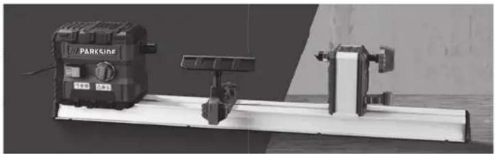
Exterior view of a mechanical testing setup with a Parkside motor and clamp, mounted on a white platform (no visible text or symbols)DRECHSELMASCHINE/LATHE/TOUR PDM 600 D2
DE AT CH
DRECHSELMASCHINE
Bedienungsanleitung
Translation of the original instructions
FR BE
TOUR
Mode d'emploi
GB/IE User manual Page 26
List of pictograms used ...... Page 27
Introduction ...... Page 27
Intended use.... Page 28
Scope of delivery ...... Page 28
Parts description.... Page 28
Technical data....Page 28
Safety instructions ...... Page 29
General power tool safety warnings.... Page 29
Safety instructions for the wood-turning machine .... Page 31
Behaviour in emergency situations.... Page 33
Residual risks....Page 33
Before first use.... Page 34
Unpacking the product.... Page 34
Preparation.... Page 34
Attaching the product.... Page 34
Installing and adjusting the tool support .... Page 34
Setting up the tool support Page 35
Adjusting the tailstock Page 35
Securing the workpiece on the headstock drive centre ........ Page 35
Assembling the face plate Page 36
Securing the workpiece on the face plate . . . . . . . . . . . . . . . . . . . . . . . . . . . . . . . . . . . . . . . . . . . . . . . . . . . . . . . . . . . . . . . . . . . . . . . . . . . . . . . 36
Operation.... Page 37
Switching on and off.... Page 37
Adjusting the speed ...... Page 37
Important information for operation....Page 37
Cleaning and care Page 38
Cleaning Page 38
Maintenance....Page 38
Repair Page 39
Storage Page 39
Transportation.... Page 39
Troubleshooting Page 39
Disposal Page 40
Warranty.... Page 40
Warranty claim procedure.... Page 41
Service Page 41
EU declaration of conformity....Page 42
| List of pictograms used | |||
 | DANGER! – Designating a hazard with high risk, which will result in death or severe injury if not avoided (e.g. risk of suffocation) |  | Wear hearing protection. |
 | Wear eye protection. | ||
 | WARNING! – Designating a hazard with moderate risk, which can result in death or severe injury if not avoided (e.g. risk of electric shock) |  | Wear dust protection. |
 | Wear a hair net. | ||
 | CAUTION! – Designating a hazard with low risk, which could result in minor or moderate injury if not avoided (e.g. risk of scalding) |  | Switch off the product and remove the mains plug 16 from the mains socket before making any adjustments, performing maintenance, cleaning and when the product is not in use. |
 | NOTICE! – Warns of possible damage to property/the product if not avoided (e.g. risk of short circuit) |  | The use of gloves is prohibited. |
 | Read the user manual. Alternating current/voltage | ||
 | Direction of rotation |  | Symbol for a protection class II product |
 | CE mark indicates conformity with relevant EU directives applicable for this product. | [A23B] | Safety information Instructions for use |
LATHE
● Introduction
We congratulate you on the purchase of your new product. You have chosen a high quality product. The instructions for use are part of the product. They contain important information concerning safety, use and disposal.
Before using the product, please familiarise yourself with all of the safety information and instructions for use. Only use the product as described and for the specified applications. If you pass the product on to anyone else, please ensure that you also pass on all the documentation with it.
Intended use
The lathe (hereinafter “product” or “power tool”) is intended for processing wood using a suitable turning tool. Cutting in wet condition and cutting metal or plastic are prohibited.
■ Any other use or modification of the product are considered improper use and can result in hazards such as death, life-threatening injuries and damage.
The manufacturer is not liable for any damages caused by improper use.
- The product is exclusively intended for domestic use.
The product is not intended for commercial use, industrial operations or similar purposes.
- Observe all applicable local safety regulations, standards and ordinances. The use of noise emitting power tools may be restricted to certain times by national or local regulations.
- Scope of delivery
WARNING!
The product and the packaging are not children's toys! Children must not play with plastic bags, sheets and small parts! There is a danger of choking and suffocation!
After unpacking the product, check if the delivery is complete and if all parts are in good condition. Remove all packaging materials before use.
1 Lathe
1 Tool support
1 Tailstock
1 Machine bed
1 Face plate
2 Spanners (size 24)
1 Wood-turning chisel (flat/angular)
1 Wood-turning chisel (hollow)
1 Tightening wheel (for the tool support)
8 Fastening screws
1 Screw
1 User manual
Parts description
(Fig. A)
1 Motor unit
2a On switch
2b Off switch
3 Speed control
4 Headstock drive centre
5 Tool support base
6 Tool support
7 Centring pin
8 Lock nut
9 Tailstock
10Hand wheel
11 Clamping lever (tailstock)
12Machine bed
13Locking screw
15 Spanners
16Mains cord with mains plug
14 Tightening wheel (for the tool support)
A Elongated holes
B Fastening screws
(Fig. B)
17Screw
(Fig. F)
18Face plate
- Technical data
| Lathe PDM 600 D2 | |
| Model number:-with VDE plug: HG12013-with CH plug: HG12013-CH | |
| Rated voltage: 230-240 V~, 50 Hz | |
| Nominal output: 550 W | |
| Operating mode: S1 * | |
| Idle speed n_0 : | 800–3000 min ^-1 |
| Max. workpiece length: 60 cm | |
| Max. workpiece ∅: 25 cm | |
| Spindle head thread: M 18 × 1.5 | |
| Weight: approx. 6.5 kg | |
| * Operating mode S1, continuous operation | |
Noise emission value
Noise measurement value determined in accordance with EN 62841. The A-rated noise level of the power tool at the working location is typically as follows:
| Sound pressure level L_pA : 88.1 dB | |
| Uncertainty K_pA : 3 dB | |
| Sound power level L_WA : 101.1 dB | |
| Uncertainty K_WA : 3 dB | |

WARNING!

Wear hearing protection!
NOTE
The noise emission values given in these instructions have been measured in accordance with a standardised test procedure and can be used for comparison of the power tool with another tool.
The noise emission values can also be used to make a provisional load estimate.

WARNING!
Depending on the manner in which the power tool is being used and, in particular, the kind of workpiece being worked, the noise emission values can deviate from the values given in these instructions during actual use of the power tool.
It is necessary to establish safety measures to protect the operator based on an estimation of the vibration load during actual use (wherein all states of operation must be included, e.g. times when the power tool is switched off and times where the power tool is switched on but running without load).

Safety instructions
● General power tool safety warnings

WARNING!
Read all safety warnings, instructions, illustrations and specifications provided with this power tool. Failure to follow all instructions listed below may result in electric shock, fire and/or serious injury.
Save all warnings and instructions for future reference.
The term “power tool” in the warnings refers to your mains-operated (corded) power tool or battery-operated (cordless) power tool.
Work area safety
a) Keep work area clean and well lit. Cluttered or dark areas invite accidents.
b) Do not operate power tools in explosive atmospheres, such as in the presence of flammable liquids, gases or dust. Power tools create sparks which may ignite the dust or fumes.
c) Keep children and bystanders away while operating a power tool. Distractions can cause you to lose control.
Electrical safety
a) Power tool plugs must match the outlet. Never modify the plug in any way. Do not use any adapter plugs with earthed (grounded) power tools. Unmodified plugs and matching outlets will reduce risk of electric shock.
b) Avoid body contact with earthed or grounded surfaces, such as pipes, radiators, ranges and refrigerators. There is an increased risk of electric shock if your body is earthed or grounded.
c) Do not expose power tools to rain or wet conditions. Water entering a power tool will increase the risk of electric shock.
d) Do not abuse the cord. Never use the cord for carrying, pulling or unplugging the power tool. Keep cord away from heat, oil, sharp edges or moving parts. Damaged or entangled cords increase the risk of electric shock.
e) When operating a power tool outdoors, use an extension cord suitable for outdoor use. Use of a cord suitable for outdoor use reduces the risk of electric shock.
f) If operating a power tool in a damp location is unavoidable, use a residual current device (RCD) protected supply. Use of an RCD reduces the risk of electric shock.
Personal safety
a) Stay alert, watch what you are doing and use common sense when operating a power tool. Do not use a power tool while you are tired or under the influence of drugs, alcohol or medication. A moment of inattention while operating power tools may result in serious personal injury.
b) Use personal protective equipment. Always wear eye protection. Protective equipment such as dust mask, non-skid safety shoes, hard hat, or hearing protection used for appropriate conditions will reduce personal injuries.
c) Prevent unintentional starting. Ensure the switch is in the off-position before connecting to power source and/or battery pack, picking up or carrying the tool. Carrying power tools with your finger on the switch or energising power tools that have the switch on invites accidents.
d) Remove any adjusting key or wrench before turning the power tool on. A wrench or a key left attached to a rotating part of the power tool may result in personal injury.
e) Do not overreach. Keep proper footing and balance at all times. This enables better control of the power tool in unexpected situations.
f) Dress properly. Do not wear loose clothing or jewellery. Keep your hair, clothing and gloves away from moving parts. Loose clothes, jewellery or long hair can be caught in moving parts.
g) If devices are provided for the connection of dust extraction and collection facilities, ensure these are connected and properly used. Use of dust collection can reduce dust-related hazards.
h) Do not let familiarity gained from frequent use of tools allow you to become complacent and ignore tool safety principles. A careless action can cause severe injury within a fraction of a second.
Power tool use and care
a) Do not force the power tool. Use the correct power tool for your application. The correct power tool will do the job better and safer at the rate for which it was designed.
b) Do not use the power tool if the switch does not turn it on and off. Any power tool that cannot be controlled with the switch is dangerous and must be repaired.
c) Disconnect the plug from the power source and/or the battery pack, if detachable, from the power tool before making any adjustments, changing accessories, or storing power tools. Such preventive safety measures reduce the risk of starting the power tool accidentally.
d) Store idle power tools out of the reach of children and do not allow persons unfamiliar with the power tool or these instructions to operate the power tool. Power tools are
dangerous in the hands of untrained users.
e) Maintain power tools and accessories. Check for misalignment or binding of moving parts, breakage of parts and any other condition that may affect the power tool's operation. If damaged, have the power tool repaired before use. Many accidents are caused by poorly maintained power tools.
f) Keep cutting tools sharp and clean. Properly maintained cutting tools with sharp cutting edges are less likely to bind and are easier to control.
g) Use the power tool, accessories and tool bits etc. in accordance with these instructions, taking into account the working conditions and the work to be performed. Use of the power tool for operations different from those intended could result in a hazardous situation.
h) Keep handles and grasping surfaces dry, clean and free from oil and grease. Slippery handles and grasping surfaces do not allow for safe handling and control of the tool in unexpected situations.
Service
a) Have your power tool serviced by a qualified repair person using only identical replacement parts. This will ensure that the safety of the power tool is maintained.
● Safety instructions for the wood-turning machine
- Familiarise yourself with the properties of the machine and the wood-turning technology before starting the machine.
- Check all workpieces for cracks or knots. Adhesive joints must be fully hardened before turning.
■ Make sure the workpiece is securely engaged and all attachments are secured.
Before switching on the machine, ensure that the workpiece can turn freely by turning it by hand. - Keep your hands and fingers away from the rotating workpiece.
- Switch off the machine and wait until it has come to a standstill before adjusting the workpiece, tailstock or tool support.
- Maintenance, setting, calibration and cleaning may only be carried out with the engine switched off.
The machine is only intended for use with wood-turning chisels.
■ Always store the wood-turning chisel in a safe place before leaving the workplace. - Do not operate the wood-turning machine without covers and protective devices.
- Keep cutting tools sharp.
- Use the lowest speed when starting a new workpiece.
■ Always stop the wood-turning machine at the slowest speed. If the wood-turning machine runs so fast that it vibrates, there is a danger that the workpiece will be thrown or the cutting tool pulled out of your hands. - Do not let cutting tools bite into the workpiece. The wood can be split or thrown from the lathe.
■ Always position the tool support above the centre line of the wood-turning machine when shaping a workpiece.
Before attaching a workpiece to the front plate, always plan as roughly as possible to make it as round as possible. This minimises the vibrations when rotating the workpiece. Always attach the workpiece securely to the
front plate. Otherwise the workpiece can be thrown away from the woodturning machine.
■ Use a brush or compressed air to remove wood chippings; never your hands. The chips will be sharp.
The cutting tool must always sit firmly in the clamping chuck and be adjusted so that the protrusion from the piece of wood is limited. This reduces the chance of the tool breaking or bending.
The wood-turning machine must not be crossed while it is in operation.
- Only insert the workpiece into a cutting tool against the direction of rotation. The workpiece must always turn towards you.
- Do not leave the device unattended when it is plugged into a socket, turn it off and pull it out of the socket before leaving it.
This product is not a toy. Keep out of the reach of children.
■ Some dusts caused by the machining contain chemicals known to cause cancer, birth defects, or other reproductive harm. Some examples of these chemicals are:
—Lead from lead paints
- Crystalline silica from bricks and cement or other masonry products
- Arsenic and chromium from chemically treated wood
- Your risk will vary depending on how often you carry out this work. To reduce your exposure to these chemicals: Work in a well-ventilated area and work with approved safety devices, such as dust masks that have been specially designed to filter out microscopic particles.
- People with pacemakers should consult their doctor before use. Electromagnetic fields in the vicinity of the pacemaker can interfere with the pacemaker or cause the pacemaker to fail. Furthermore, people with pacemakers should: -Avoid working alone.
■ Properly maintain and check to avoid an electric shock.
The warnings, precautionary measures and instructions described in this user manual cannot cover all possible conditions and situations. The operator must understand that common sense and caution are factors that cannot be built into this product but must be provided by the operator.
Additional safety instructions for the use of face plates
■ Make sure the face plate is the correct size to support the workpiece.
■ Make sure that the workpiece is securely attached to the face plate.
Before mounting the workpiece on a face plate, cut the workpiece as close as possible to the final shape.
Only use a scraper chisel to turn the face plate. Cutting chisels can be pulled out of your hands easily.
■ Make sure that the wood-turning chisel cannot interfere with the retaining screws on the finished dimensions of the workpiece.
● Behaviour in emergency situations
Familiarise yourself with the use of this product by means of this instruction manual. Memorise the safety warnings and follow them to the letter. This will help to prevent risks and hazards.
■ Always be alert when using this product, so that you can recognise and handle risks early. Fast intervention can prevent serious injury and damage to property.
- Switch the product off and disconnect it from the mains if there are malfunctions. Have the product checked by a qualified professional and repaired, if necessary, before you operate it again.
Residual risks
Even if you are operating this product in accordance with all the safety requirements, potential risks of injury and damage remain. The following dangers can arise in connection with the structure and design of this product:
■ Only use selected timbers without faults such as:
-Knots
-Transverse cracks
-Surface cracks
Defective wood is prone to splintering and becomes a risk when working.
- Timbers that are not carefully glued can explode due to the centrifugal force during machining.
Before clamping: Cut the raw workpiece into a square shape, centre it and ensure that it is securely clamped. Imbalance in the workpiece leads to the danger of injury.
- Danger of injury due to unsafe tool guidance if the tool support is not positioned precisely and the wood-turning tool is blunt. A prerequisite for correct wood-turning is a flawless, sharpened wood-turning tool.
- Danger to health due to the rotating workpiece if hair is long and clothing loose. Wear personal protective equipment such as a hair net and close-fitting clothing.
- Risk to health from wood dust or wood chippings. Wear personal protective equipment such as protective goggles and dust masks.
■ Health hazard due to electrical power, with the use of improper electrical connection cables.
■ Furthermore, despite all precautions having been met, some non-obvious residual risks may still remain. - Residual risks can be minimised if the chapters “Safety instructions” and “Intended use” are observed along with the whole of the user manual.
Before performing setting or maintenance work: Switch off the product. Remove the mains plug from the mains socket.
Before first use
● Unpacking the product
- Take the product out of the packaging and remove all packaging materials and plastic wrappings.
- Check to make sure that all listed parts are included (see "Scope of delivery").
- Check whether the product and all parts are in good condition, if any damage or defect is detected, do not use the product, but follow the procedure described in chapter "Warranty".
● Preparation
⚠ WARNING! Risk of electric shock!
The data on the type plate has to match with the mains power data.
Only connect the product to a correctly installed protective mains socket, with fuse protection of at least 16 A.
⚠ WARNING! Risk of injury!
Prepare the workplace where you want to set up the product. Ensure there is sufficient space to guarantee safe and trouble-free operation. The product is designed for working in enclosed rooms and must be set up on a level and firm surface.
Install the product securely, i.e. bolted down on a workbench, machine stand or similar.
Prior to commissioning: All covers and safety devices must be mounted correctly.
In case of previously machined wood: Be aware of any foreign bodies, such as nails or screws, etc.
⚠ WARNING! Risk of injury!

Always remove the mains plug 16 from the mains socket before carrying out any work on the product.
- Attaching the product
Fig. A
☐ Use the elongated holes A and fastening screws B to screw the product onto a workbench, machine stand or similar before commissioning.
- Installing and adjusting the tool support
Fig. B, C
- Use the screw 17 to fix the tightening wheel 14 onto the bottom of the tool support base 5 (Fig. B).
- Plug the tool support 6 in the mounting hole of the tool support base 5 (Fig. C).
- Use the locking screw 13 to fasten the tool support 6 at the desired height.
- Setting up the tool support
- Loosening the tool support 6: Turn the locking screw 13 in anticlockwise direction.
- Loosening the tool support base 5: Turn the tightening wheel 14 in anticlockwise direction.
- Set the position of the tool support 6. The tool support must be driven as close as possible to the workpiece without touching it.
- Locking the tool support 6: Turn the locking screw 13 in clockwise direction.
- Locking the tool support base 5: Turn the tightening wheel 14 in clockwise direction.
- Adjusting the tailstock
Fig. D
⚠ WARNING! Risk of injury!
▶ Tighten the tool support 6 firmly so that it cannot turn towards the workpiece.
NOTE
The clamp is spring loaded.
If you experience strong resistance: Start from lifting the clamping lever 11 up.
-
Unlock the clamping lever 11 of the tailstock 9 to set the distance between the tailstock and the headstock drive centre 4.
-
Once the desired tailstock 9 position has been reached: Lock the clamping lever 11 again.
Unlocking the clamping lever
- Turn the clamping lever 11 in anticlockwise direction as far as possible.
-
Lift the clamping lever 11 up. Turn the clamping lever in clockwise direction.
-
Push the clamping lever 11 down.
- Depending on how much the clamping lever 11 was turned: Repeat 4 to 7 times.
Locking the clamping lever
- Turn the clamping lever 11 in clockwise direction as far as possible.
- Lift the clamping lever 11 up. Turn the clamping lever in anticlockwise direction.
- Push the clamping lever 11 down.
- Depending on how much the clamping lever 11 was turned: Repeat 4 to 7 times.
Securing the workpiece on the headstock drive centre
Fig. E
⚠ NOTICE! Risk of product damage!
Before starting the product: Rotate a workpiece by hand to check the setup. Ensure that:
- There is enough free space between the product and the workpiece
- The workpiece does not come into contact with the tool support 6
NOTE
A wooden hammer (not included in the scope of delivery) is required for this step.
If the diameter of the ends is greater than 5 cm: Cut the corners off the workpiece. This makes turning easier and safer.
-
Loosening the headstock drive centre 4: Use the spanners 15.
-
Locating the centre of the workpiece: Draw precise diagonal lines at both ends of the workpiece. The intersection of these 2 lines indicates the centre of the workpiece.
-
At the end of the workpiece: Produce an approx. 2 mm deep saw cut along the diagonal, in order to receive the headstock drive centre 4.
- Use a wooden hammer to lightly tap the headstock drive centre 4 into the centre of the diagonal cuts over the end of the workpiece. Protect the threaded end of the headstock drive centre so that no object damages the thread.
- Measure the total length of the workpiece: Use the headstock drive centre 4 and the centring pin 7 at each end.
- Loosen the tightening lever 11. Set the distance between the headstock drive centre 4 and the centring pin 7, such that a slightly greater distance is obtained than the measured total length of the workpiece.
- Screw the headstock drive centre 4 with the workpiece onto the motor unit 1.
- Use the hand wheel 10 to adjust the clamping pressure. Secure the centring pin 7 with the lock nut 8.
- Set the tool support base 5 with tool support 6 approx. 3 mm away from the workpiece.
- Assembling the face plate
Fig. F
NOTE
The face plate ^18 provides a firm and secure hold for a large number of turned objects such as plates, bowls, pots and round parts.
- Loosen the headstock drive centre 4 (see "Securing the workpiece on the headstock drive centre").
- Screw the face plate 18 onto the spindle of the headstock. Tighten with the spanner 15 by hand.
● Securing the workpiece on the face plate
⚠ NOTICE! Risk of product damage!
The wood-turning chisel should not touch the retaining screws on the finished dimensions of the workpiece.
NOTE
Workpieces that cannot be machined with the headstock drive centre 4 must instead be mounted on a face plate 18 or a counter piece, such as a clamping chuck or wooden block.
Attaching the face plate ^18 to the workpiece: This can be done using wood screws (not included in the scope of delivery) that are screwed directly into the workpiece.
If the intended cutting dimensions do not permit screws: A counter piece may be required.
- Before mounting on the face plate 18: Cut the workpiece as close as possible to the final shape.
- Attach the face plate 18 securely to the workpiece. Use a counter piece if required (see "Making a counter piece").
Making a counter piece
NOTE
Only use non-conical wood screws. Do not use wood screws with a conical head.
- Use an old wooden block with 2 flat and parallel opposing surfaces.
- Identify and mark the centre of the carrier part.
-
Bond the carrier part (wooden block) with the workpiece, if required.
-
Attach the workpiece to the carrier part.
- Use screws (not included in the scope of delivery) to fasten the workpiece to the face plate 18.
- Clamp the carrier part to the workpiece and wait until the glue has dried as per the recommendation of the glue manufacturer.
- If the use of screws in the workpiece is not permitted: Glue the workpiece with a piece of paper between the joint. This enables later separation without damaging the workpiece.
Operation
- Switching on and off
⚠ WARNING! Risk of injury!
The product starts running immediately at the set speed.
□ Switching on: Set the on switch 2a to position I.
☐ Switching off: Set the on switch 2b to position O.
- Adjusting the speed
NOTE
The correct speed must be set depending on the workpiece to be processed.
▶ Use the electronic speed control to steplessly set the speed.
- Setting the speed: Use the speed control 3. The required speed depends on the workpiece diameter.
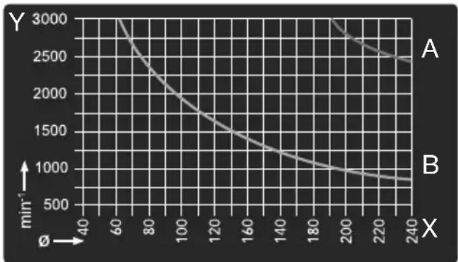
line
| X | Y | | ---- | ----- | | 60 | 3000 | | 80 | 2500 | | 100 | 2000 | | 120 | 1750 | | 140 | 1500 | | 160 | 1250 | | 180 | 1000 | | 200 | 900 | | 220 | 850 | | 240 | 800 || Axis Indicator | |
| X ∅ Workpiece diameter | |
| Y min | -1 Speed |
| Curve Indicator |
| A Maximum speed |
| B Ideal speed |
- Start with the diameter of the workpiece and follow it vertically upwards.
- Read out the speed at which the vertical line meets the curve.
- Important information for operation
NOTE
Refer to the specialist literature on wood-turning techniques.
When choosing the wood for your turning work: Pay attention to knots and contraction movements. Only use wood that is free of cracks and knots (with small knots, pay attention to the pressure with the turning tool).
Always check that the moulded part is held securely by checking it by hand.
▶ Only use an original turning tool that is sharp.
NOTE
When turning wooden disks: Do not stand in the trajectory of the workpiece.
Use a band saw or jigsaw to cut large and unbalanced moulded parts as well as possible. If the moulded parts are very unbalanced, they pose a danger to your health and the service life of the product.
Always start with the lowest possible speed for new workpieces and increase it as the solidity of the workpiece to be turned grows.
Do not use wooden disks with contraction cracks. Such disks represent a high danger of bursting when exposed to centrifugal forces.
Do not exceed the maximum workpiece sizes.
If the product is blocked: First remove the mains plug 16 from the mains socket before starting troubleshooting.
For your turning work: Position yourself at the product so that you can guide the chisels effectively on the tool carrier.
Only use cutting tools that are recommended for wood-turning work.
● Cleaning and care

WARNING! Risk of injury!

Always switch the product off, remove the mains plug 16 from the mains socket and let the product cool before performing inspection, maintenance and cleaning work!
Cleaning

NOTICE! Risk of product damage!
Do not use chemical, alkaline, abrasive or other aggressive detergents or disinfectants to clean this product as they might be harmful to its surfaces.
▶ Never allow fluids to get into the product.
NOTE
Always keep the product clean, dry and free from oil or grease.
▶ Regular and proper cleaning helps ensure safe use and prolong the life of the product.
□ After each use and before storage: Remove debris from the product.
□ Clean the product with a dry cloth. Use a soft brush for areas that are hard to reach.
Maintenance
■ The product is maintenance-free.
Before and after each use: Check the product and accessories (e.g. saw blades) for wear and damage. If required, exchange them for new ones as described in this instruction manual. Observe the technical requirements (see “Technical data”).
☐ Check covers and safety devices for damages and correct installation. Replace as necessary.
Replacement parts/Accessories
□ Customers can obtain compatible replacement parts and accessories via www.optimex-shop.com.
□ Have the order number ready for your order.
☐ Orders can only be placed and processed online.
☐ Contact the Lidl service hotline (see “Service”) for further information.
| Part Order number | |
| 15 Spanners 99945873001 | |
| 18 Face plate 99945873004 | |
| Wood-turning chisel (flat/angular) 99945873005 | |
| Wood-turning chisel (hollow) 99945873002 | |
| B Fastening screw 99945873003 | |
Repair
If the mains cord 16 is damaged, it must be replaced by the manufacturer, its service agent or similarly qualified persons in order to avoid a hazard.
☐ This product does not contain any parts that can be repaired by the user. Contact an authorised service centre or a similarly qualified person to have it checked and repaired.
Storage
☐ Before storage: Clean the product (see “Cleaning”).
☐ Store the product and its accessories in a dark, dry, frost-free, well-ventilated place.
□ Always store the product in a place that is inaccessible to children.
□ Store the product in its original package.
- Transportation
■ Before transporting the product: Switch off the product. Disconnect the product from the mains supply.
□ Always carry the product with at least one other person. Carry the product on the machine bed 12.
☐ Protect the product from impacts, shocks and severe vibrations, e.g. during vehicular transport.
☐ Secure the product against toppling and slipping.
□ Never use protective devices for handling or transport.
□ Transport the product in its original package.
● Troubleshooting
| Issue Possible cause | Solution | |
| The cut quality is poor. | Cutting tool is brunt. Sharpen or replace cutting tool. | |
| Cut too aggressively. Reduce the work pressure. | ||
| The cutting tool is positioned below the workpiece centreline. | Do not apply the cutting tool any lower than 3 mm above the centre of the workpiece. | |
| Turning speed too slow | Adjust the speed (see „Adjusting the speed“). | |
| Excessive vibration when turning thin workpieces. | The cutting tool is below the workpiece centreline. | Raise the cutting tool to the centreline of the workpiece. |
| Cut too aggressively. Reduce the work pressure. | ||
| Excessive vibration when turning large workpieces or bowls. | Headstock and/or tailstock 9 incorrectly positioned at the ends of the workpiece. | Check whether the workpiece tips on the headstock and/or tailstock 9 are properly attached to the centre of the workpiece. |
| The workpiece is not balanced. | Cut the end of the part until the workpiece is balanced. | |
| The product does not work. | Mains plug 16 not connected to the mains socket. | Connect the mains plug 16 to the mains socket. |
| The product does not turn off. | Damaged or defective power switch and/or internal wiring. | Remove the mains plug 16 from the mains socket immediately. Do not operate the product until it has been repaired by a qualified service technician. |
- Disposal
The packaging is made entirely of recyclable materials, which you may dispose of at local recycling facilities.

Observe the marking of the packaging materials for waste separation, which are marked with abbreviations (a) and numbers (b) with following meaning: 1–7: plastics/20–22: paper and fi breboard/80–98: composite materials.
Product:


The product and packaging materials are recyclable and are subject to extended producer responsibility.
Dispose them separately, following the illustrated Info-tri (sorting information), for better waste treatment.
The Triman logo is valid in France only.

Contact your local refuse disposal authority for more details of how to dispose of your worn-out product.

To help protect the environment, please dispose of the product properly when it has reached the end of its useful life and not in the household waste. Information on collection points and their opening hours can be obtained from your local authority.
Warranty
The product has been manufactured to strict quality guidelines and meticulously examined before delivery. In the event of material or manufacturing defects you have legal rights against the retailer of this product. Your legal rights are not limited in any way by our warranty detailed below.
The warranty for this product is 3 years from the date of purchase. The warranty period begins on the date of purchase. Keep the original sales receipt in a safe location as this document is required as proof of purchase.
Any damage or defects already present at the time of purchase must be reported without delay after unpacking the product.
Should the product show any fault in materials or manufacture within 3 years from the date of purchase, we will repair or replace it – at our choice – free of charge to you. The warranty period is not extended as a result of a claim being granted. This also applies to replaced and repaired parts.
This warranty becomes void if the product has been damaged, or used or maintained improperly.
The warranty covers material or manufacturing defects. This warranty does not cover product parts subject to normal wear and tear, thus considered consumables (e.g. batteries, rechargeable batteries, tubes, cartridges), nor damage to fragile parts, e.g. switches or glass parts.
● Warranty claim procedure
So that your request can be processed quickly, please observe the following instructions:
For all inquiries, please have the receipt and item number (IAN 458730_2401) ready as proof of purchase.
The article number can be taken from the identification label on the product, engraving on the product, the front cover of your manual (at the bottom left), or the sticker on the back or bottom of the product.
If malfunctions or other defects arise, first contact the service department indicated below by phone or email.
You can then send a product recorded as defective to the communicated service address postage-free, making sure to enclose proof of purchase (receipt) and information on the details of the defect and when it occurred.

You can download and view this and numerous other manuals at parkside-diy.com. This QR code takes you directly to parkside-diy.com. Choose your country and use the search screen to search for the operating instructions. Entering the item number (IAN) 458730_2401 takes you to the operating instructions for your item.
Service
GB Service Great Britain
Tel.: 0800 0569216
E-Mail: owim@lidl.co.uk
IE Service Ireland
Tel.: 1800 200736
E-Mail: owim@lidl.ie
● EUdeclarationofconformity
EU DECLARATION OF CONFORMITY (No 458730\_2401)
IAN: 458730_2401
Product identification:
"PARKSIDE" Lathe
Model Number: HG12013
The object of the declaration described above is in conformity with the relevant Union harmonisation legislation:
| Directive 2006/42/EC |
| Directive 2014/30/EU |
| Directive 2011/65/EU and all related amendments |
References to the relevant harmonised standards used or references to the other technical specifications in relation to which conformity is declared:
| N° / Parts |
| Directive 2006/42/EC |
| EN 62841-1:2015/A11:2022 |
| EN ISO 12100:2010 |
| Directive 2014/30/EU |
| EN IEC 55014-1:2021 |
| EN IEC 55014-2:2021 |
| EN IEC 61000-3-2:2019/A1:2021 |
| EN 61000-3-3:2013/A1:2021 |
The object of the declaration described above is in conformity with Directive 2011/65/EU of the European Parliament and of the Council of 8 June 2011 on the restriction of the use of certain hazardous substances in electrical and electronic equipment:
| N° / Parts |
| EN IEC 63000:2018 |
Keeper of the technical documentation: OWIM GmbH & Co.KG
Signed for and on behalf of:
This declaration of conformity is issued under the sole responsibility of the manufacturer.
Translation of the original declaration of conformity
Authorised Signatory Authorised Signatory
EN
CE
De klem is veerbelast.
Als u sterke weerstand ondervindt: Trek eerst de spanher 11 ol omhoog.
PDF ONLINE
parkside-diy.com