PFBS 160 D3 - Grinder PARKSIDE - Free user manual and instructions
Find the device manual for free PFBS 160 D3 PARKSIDE in PDF.

| Product Type | Precision Grinder |
| Brand | Parkside |
| Model | PFBS 160 D3 |
| Rated Power | 160 W |
| Rated Voltage | 230–240 V~, 50 Hz |
| No-Load Speed | 10,000 to 40,000 min⁻¹ |
| Max. Drill Diameter | 3.2 mm |
| Max. Disc Diameter | 25 mm |
| Protection Class | II (Double Insulation) |
| Power Supply | Mains (with cord) |
| Main Functions | Drilling, milling, engraving, polishing, cleaning, sanding, cutting |
| Workable Materials | Wood, metal, plastic, ceramic, stone |
| Included Accessories | 42 pieces (grinding stone, brushes, collets, drill bits, etc.) + flexible shaft + tripod + case |
| Lighting | Integrated LED work light in the grip ring |
| Sound Pressure Level LpA | 75.3 dB (uncertainty 3 dB) |
| Total Vibration ah | 1.637 m/s² (uncertainty 1.5 m/s²) |
| Maintenance | Clean with damp cloth, replace carbon brushes if necessary |
| Safety | Wear safety goggles, disconnect before maintenance, use PPE |
| Spare Parts | Available at www.optimex-shop.com |
| Warranty | 3 years (subject to legal conditions) |
| Dimensions (approx.) | Approx. 300 x 80 x 80 mm |
| Weight (approx.) | Approx. 1.2 kg |
Frequently Asked Questions - PFBS 160 D3 PARKSIDE
User questions about PFBS 160 D3 PARKSIDE
0 question about this device. Answer the ones you know or ask your own.
Ask a new question about this device
Download the instructions for your Grinder in PDF format for free! Find your manual PFBS 160 D3 - PARKSIDE and take your electronic device back in hand. On this page are published all the documents necessary for the use of your device. PFBS 160 D3 by PARKSIDE.
USER MANUAL PFBS 160 D3 PARKSIDE
PDF ONLINE
parkside-diy.com

natural_image
Black Parkside electric drill bit with visible screw and head (no text or symbols on body)FEINBOHRSCHLEIFER/FINE DRILL GRINDER/MEULEUSE DE PRÉCISION PFBS 160 D3
DE AT CH
FEINBOHRSCHLEIFER
Bedienungsanleitung
Translation of the original instructions
FR BE
MEULEUSE DE PRÉCISION
Mode d'emploi
GB/IE User manual Page 31

Intended use.... Page 33
Scope of delivery ...... Page 34
Description of parts ...... Page 34
Technical data. Page 35
Safety instructions ...... Page 36
General power tool safety warnings ...... Page 36
Safety instructions for all operations Page 38
Further safety instructions for all operations.... Page 40
Additional safety instructions for grinding and cutting-off operations.. Page 40
Additional safety instructions for wire brushing operations ..... Page 41
Safety instructions for LED lights....Page 42
Safety instructions for batteries/rechargeable batteries. . . . . . . . . . . . . . . . . . . . . . . . . . . . . . . . . . . . . . . . . . . . . . . . . . . . . . . . . . . . . . . . . . . . . . . . . . . . . . . . . . . . Page 42
Notes for coin/button cell batteries Page 42
Original accessories/auxiliary equipment. Page 43
Before first use.... Page 43
Unpacking the product. Page 43
Preparation.... Page 43
Inserting/changing the tool/collet chuck Page 43
Grindstone Page 43
Fitting an abrasive belt....Page 43
Fitting a polishing attachment . . . . . . . . . . . . . . . . . . . . . . . . . . . . . . . . . . . . . . . . . . . . . . . . . . . . . . . . . . . . . . . . . . . . . . . . . . . . . . . . . Page 44
Operation.... Page 44
Setting the speed range ...... Page 44
Switching on and off.... Page 44
Using the grip ring with LED work light . . . . . . . . . . . . . . . . . . . . . . . . . . . . . . . . . . . . . . . . . . . . . . . . . . . . . . . . . . . . . . . . . . . . . . . . Page 44
Notes on working with materials/tools/speed range . . . . . . . . . . . . . . . . . . . . . . . . . . . . . . . . . . . . . . . . . . . . . . . . . . . . . . . . . . . . . . . . . . . . . . . . . . . . . . . . . . . . . . . Page 44
Fitting/using the flexible shaft. Page 47
Stand Page 47
Router cage Page 47
Replacing the button cells Page 48
Cleaning, maintenance and storage.... Page 48
Cleaning Page 48
Replacing the carbon brush.... Page 48
Maintenance Page 48
Storage Page 49
Replacement parts/Accessories.... Page 49
Disposal Page 49
Warranty.... Page 49
Warranty claim procedure.... Page 50
Service Page 50
EU Declaration of conformity.... Page 51
| List of pictograms used | |||
 | DANGER! - Designating a hazard with high risk, which will result in death or severe injury if not avoided (e.g. risk of suffocation) |  | Read the user manual. |
 | Wear eye protection! | ||
 | WARNING! - Designating a hazard with moderate risk, which can result in death or severe injury if not avoided (e.g. risk of electric shock) |  | Unplug |
| ~ | Alternating current/voltage | ||
 | CAUTION! - Designating a hazard with low risk, which could result in minor or moderate injury if not avoided (e.g. risk of scalding) |  | Protection class II (double insulation) |
 | Keep out of reach of children. | ||
 | NOTICE! - Warns of possible damage to property/the product if not avoided (e.g. risk of short circuit) | [A43W] | Safety information Instructions for use |
 | CE mark indicates conformity with relevant EU directives applicable for this product. | ||
FINE DRILL GRINDER
● Introduction
We congratulate you on the purchase of your new product. You have chosen a high quality product. The instructions for use are part of the product. They contain important information concerning safety, use and disposal.
Before using the product, please familiarise yourself with all of the safety information and instructions for use.
Only use the product as described and for the specified applications. If you pass the product on to anyone else, please ensure that you also pass on all the documentation with it.
Intended use
The product is intended for the following work:
-Drilling
-Milling
-Engraving
-Polishing
-Cleaning
-Grinding
-Cutting
Following materials can be processed with the product:
-Wood
-Metal
-Plastic
-Ceramics
-Stone
The LED work light ^10 is intended to illuminate the immediate work area.
Always use the correct type of accessories according to the intended use. Observe the technical requirements of this product (see “Technical data”) when purchasing and using accessory tools!
- Use the product in dry indoor spaces only.
■ Any other use or modification of the product are considered improper use and can result in hazards such as death, life-threatening injuries and damage.
The manufacturer is not liable for any damages caused by improper use.
The operator or user of the product is responsible for any accidents or personal injury and/or material damage to third parties or their property.
The product is exclusively intended for domestic use.
■ The product is not intended for commercial use or for similar uses.
- Scope of delivery
WARNING!
The product and the packaging are not children's toys! Children must not play with plastic bags, sheets and small parts! There is a danger of choking and suffocation!
1 Fine drill grinder
1 Flexible shaft
1 Stand
1 Clamping device
1 Router cage
1 Grip ring with LED work light
2 Button cells (expiry date: 02/2028)
1 Accessories kit (42 pieces)
1 Storage case
1 User manual
• Description of parts
Before reading, unfold the pages containing the illustrations and familiarise yourself with all functions of the product.
(Fig. A)
1 Carbon brush cover
2 Speed control
3 On/off switch
4 Mains cord with mains plug
5 Metal bracket
6 Ventilation slots
7 Union nut
8 Clamping nut
9 Collet chuck 3.2 mm (pre-assembled)
10 Grip ring with LED work light
11 Spindle lock button
(Fig. B)
12Clamping device
13Locking screw
14Router cage
15Union nut (flexible shaft)
16 Flexible shaft
17Spindle lock (flexible shaft)
18 Holder
19Stand
(Fig. C)
42-piece accessories kit
NOTICE!
Do not exceed the specified maximum speed (see “Notes on working with materials/tools/speed range”).
201 grindstone
211 combination spanner
222 synthetic brushes (max. 15,000 min ^-1 )
231 metal brush (max. 15,000 min ^-1 )
241 abrasive belt mandrel
255 grinding bits (max. 40,000 min ^-1 )
265 abrasive belts (max. 40,000 min ^-1 )
271 drill bit (max. 20,000 min ^-1 )
281 milling bit (max. 40,000 min ^-1 )
292 engraving bits (max. 40,000 min ^-1 )
301 mandrel for cutting/grinding discs
31 1 mandrel for polishing attachments
321 collet chuck 2.4 mm
332 grinding discs (max. 40,000 min ^-1 )
348 cutting discs (max. 40,000 min ^-1 )
356 cutting discs (max. 40,000 min ^-1 )
363 polishing attachments (max. 20,000 min ^-1 )
(Fig. D)
37 On/off switch (for LED work light)
38 Insulating strip
(Fig. H)
39 Screws
40Button cells
41 Button cell holder
- Technical data
| Fine drill grinder PFBS 160 D3 | |
| Rated power consumption: 160 W | |
| Rated voltage: 230-240 V~, 50 Hz | |
| Rated speed n: 10,000 to 40,000 min ^-1 | |
| Drills: max. ∅ 3.2 mm | |
| Discs: max. ∅ 25 mm | |
| Protection class: | II/回 (double insulation) |
| Battery information | |
| Type: LR41 | |
| Voltage: 1.5 V | |
| Chemistry: MnO | _2 , Zn |
| Battery information |
| Manufactured by: |
| Dongguan Tianqiu Enterprise Co., Ltd., Tianqiu Industrial Park, Xinji Industrial Zone, Machong Town, Dongguan, Guangdong, P.R.China |
| E-mail: office@tmmq.com |
| Imported by: |
| OWIM GmbH & Co. KG Stiftsbergstraße 1 74167 Neckarsulm GERMANY |
| E-mail: battery-service@lidl.com |
| www.owim.com |
Noise emission value
The measured values have been determined in accordance with EN 60745. The A-rated noise level of the product is typically as follows:
| Sound pressure level L_pA : | 75.3 dB |
| Uncertainty K_pA : | 3.0 dB |
| Sound power level L_WA : | 86.3 dB |
| Uncertainty K_WA : | 3.0 dB |
Total vibration value
Total vibration values (triaxial vector sum) determined in accordance with EN 60745:
| Vibration a_h : | 1.637 m/s ^2 |
| Uncertainty K: | 1.5 m/s ^2 |
NOTE
The declared vibration total value(s) and the declared noise emission value(s) have been measured in accordance with a standard test method and may be used for comparing one tool with another.
NOTE
The declared vibration total value(s) and the declared noise emission value(s) may also be used in a preliminary assessment of exposure.

WARNING!
The vibration and noise emissions during actual use of the power tool can differ from the declared values depending on the ways in which the tool is used especially what kind of workpiece is processed.
It is necessary to identify safety measures to protect the operator that are based on an estimation of exposure in the actual conditions of use (taking account of all parts of the operating cycle such as the times when the tool is switched off and when it is running idle in addition to the trigger time).

Safety instructions
● General power tool safety warnings

WARNING!
Read all safety warnings and all instructions. Failure to follow the warnings and instructions may result in electric shock, fire and/or serious injury.
Save all warnings and instructions for future reference.
The term “power tool” in the warnings refers to your mains-operated (corded) power tool or battery-operated (cordless) power tool.
Work area safety
1) Keep work area clean and well lit. Cluttered or dark areas invite accidents.
2) Do not operate power tools in explosive atmospheres, such as in the presence of flammable liquids, gases or dust. Power tools create sparks which may ignite the dust or fumes.
3) Keep children and bystanders away while operating a power tool. Distractions can cause you to lose control.
Electrical safety
1) Power tool plugs must match the outlet. Never modify the plug in any way. Do not use any adapter plugs with earthed (grounded) power tools. Unmodified plugs and matching outlets will reduce risk of electric shock.
2) Avoid body contact with earthed or grounded surfaces, such as pipes, radiators, ranges and refrigerators. There is an increased risk of electric shock if your body is earthed or grounded.
3) Do not expose power tools to rain or wet conditions. Water entering a power tool will increase the risk of electric shock.
4) Do not abuse the cord. Never use the cord for carrying, pulling or unplugging the power tool. Keep cord away from heat, oil, sharp edges or moving parts. Damaged or entangled cords increase the risk of electric shock.
5) When operating a power tool outdoors, use an extension cord suitable for outdoor use. Use of a cord suitable for outdoor use reduces the risk of electric shock.
6) If operating a power tool in a damp location is unavoidable, use a residual current device (RCD) protected supply. Use of an RCD reduces the risk of electric shock.
Personal safety
1) Stay alert, watch what you are doing and use common sense when operating a power tool. Do not use a power tool while you are tired or under the influence of drugs, alcohol or medication. A moment of inattention while operating power tools may result in serious personal injury.
2) Use personal protective equipment. Always wear eye protection. Protective equipment such as dust mask, non-skid safety shoes, hard hat, or hearing protection used for appropriate conditions will reduce personal injuries.
3) Prevent unintentional starting. Ensure the switch is in the off-position before connecting to power source and/or battery pack, picking up or carrying the tool. Carrying power tools with your finger on the switch or energising power tools that have the switch on invites accidents.
4) Remove any adjusting key or wrench before turning the power tool on. A wrench or a key left attached to a rotating part of the power tool may result in personal injury.
5) Do not overreach. Keep proper footing and balance at all times. This enables better control of the power tool in unexpected situations.
6) Dress properly. Do not wear loose clothing or jewellery. Keep your hair, clothing and gloves away from moving parts. Loose clothes, jewellery or long hair can be caught in moving parts.
7) If devices are provided for the connection of dust extraction and collection facilities, ensure these are connected and properly used. Use of dust collection can reduce dust-related hazards.
Power tool use and care
1) Do not force the power tool. Use the correct power tool for your application. The correct power tool will do the job better and safer at the rate for which it was designed.
2) Do not use the power tool if the switch does not turn it on and off. Any power tool that cannot be controlled with the switch is dangerous and must be repaired.
3) Disconnect the plug from the power source and/or the battery pack from the power tool before making any adjustments, changing accessories, or storing power tools. Such preventive safety measures reduce the risk of starting the power tool accidentally.
4) Store idle power tools out of the reach of children and do not allow persons unfamiliar with the power tool or these instructions to operate the power tool. Power tools are dangerous in the hands of untrained users.
5) Maintain power tools. Check for misalignment or binding of moving parts, breakage of parts and any other condition that may affect the power tool's operation.
If damaged, have the power tool repaired before use. Many accidents are caused by poorly maintained power tools.
6) Keep cutting tools sharp and clean. Properly maintained cutting tools with sharp cutting edges are less likely to bind and are easier to control.
7) Use the power tool, accessories and tool bits etc. in accordance with these instructions, taking into account the working conditions and the work to be performed. Use of the power tool for operations different from those intended could result in a hazardous situation.
Service
1) Have your power tool serviced by a qualified repair person using only identical replacement parts. This will ensure that the safety of the power tool is maintained.

WARNING!

Always wear safety goggles!
● Safety instructions for all operations
Safety warnings common for grinding, sanding, wire brushing, polishing, carving or abrasive cutting-off operations
1) This power tool is intended to function as a grinder, sandpaper grinder, wire brush, polisher, carving or cut-off tool. Read all safety warnings, instructions, illustrations and specifications provided with this power tool.
Failure to follow all instructions listed below may result in electric shock, fire and/or serious injury.
2) Do not use accessories which are not specifically designed and recommended by the tool manufacturer. Just because the accessory can be attached to your power tool, it does not assure safe operation.
3) The rated speed of the grinding accessories must be at least equal to the maximum speed marked on the power tool. Grinding accessories running faster than their rated speed can break and fly apart.
4) The outside diameter and the thickness of your accessory must be within the capacity rating of your power tool. Incorrectly sized accessories cannot be adequately controlled.
5) The arbour size of wheels, sanding drums or any other accessory must properly fit the spindle or collet of the power tool. Accessories that do not match the mounting hardware of the power tool will run out of balance, vibrate excessively and may cause loss of control.
6) Mandrel mounted wheels, sanding drums, cutters or other accessories must be fully inserted into the collet or chuck. If the mandrel is insufficiently held and/or the overhang of the wheel is too long, the mounted wheel may become loose and be ejected at high velocity.
7) Do not use a damaged accessory. Before each use inspect the accessory such as abrasive wheels for chips and cracks, sanding drum for cracks, tear or excess wear, wire brush for loose or cracked wires. If power tool or
accessory is dropped, inspect for damage or install an undamaged accessory. After inspecting and installing an accessory, position yourself and bystanders away from the plane of the rotating accessory and run the power tool at maximum no-load speed for one minute. Damaged accessories will normally break apart during this test time.
8) Wear personal protective equipment. Depending on application, use face shield, safety goggles or safety glasses. As appropriate, wear dust mask, hearing protectors, gloves and workshop apron capable of stopping small abrasive or workpiece fragments. The eye protection must be capable of stopping flying debris generated by various operations. The dust mask or respirator must be capable of filtrating particles generated by your operation. Prolonged exposure to high intensity noise may cause hearing loss.
9) Keep bystanders a safe distance away from work area. Anyone entering the work area must wear personal protective equipment. Fragments of workpiece or of a broken accessory may fly away and cause injury beyond immediate area of operation.
10) Hold power tool by insulated gripping surfaces only, when performing an operation where the cutting accessory may contact hidden wiring or its own cord. Cutting accessory contacting a “live” wire may make exposed metal parts of the power tool “live” and could give the operator an electric shock.
11) Always hold the tool firmly in your hand(s) during the start-up. The reaction torque of the motor, as it accelerates to full speed, can cause the tool to twist.
12) Use clamps to support workpiece whenever practical. Never hold a small workpiece in one hand and the tool in the other hand while in use. Clamping a small workpiece allows you to use your hand(s) to control the tool. Round material such as dowel rods, pipes or tubing have a tendency to roll while being cut, and may cause the bit to bind or jump toward you.
13) Position the cord clear of the spinning accessory. If you lose control, the cord may be cut or snagged and your hand or arm may be pulled into the spinning accessory.
14) Never lay the power tool down until the accessory has come to a complete stop. The spinning accessory may grab the surface and pull the power tool out of your control.
15) After changing the bits or making any adjustments, make sure the collet nut, chuck or any other adjustment devices are securely tightened. Loose adjustment devices can unexpectedly shift, causing loss of control, loose rotating components will be violently thrown.
16) Do not run the power tool while carrying it at your side. Accidental contact with the spinning accessory could snag your clothing, pulling the accessory into your body.
17) Regularly clean the power tool's air vents. The motor's fan will draw the dust inside the housing and excessive accumulation of powdered metal may cause electrical hazards.
18) Do not operate the power tool near flammable materials. Sparks could ignite these materials.
19) Do not use accessories that require liquid coolants. Using water or other liquid coolants may result in electrocution or shock.
● Further safety instructions for all operations
Kickback and related warnings
Kickback is a sudden reaction to a pinched or snagged rotating wheel, sanding band, brush or any other accessory. Pinching or snagging causes rapid stalling of the rotating accessory which in turn causes the uncontrolled power tool to be forced in the direction opposite of the accessory's rotation.
For example, if an abrasive wheel is snagged or pinched by the workpiece, the edge of the wheel that is entering into the pinch point can dig into the surface of the material causing the wheel to climb out or kick out. The wheel may either jump toward or away from the operator, depending on direction of the wheel's movement at the point of pinching. Abrasive wheels may also break under these conditions.
Kickback is the result of power tool misuse and/or incorrect operating procedures or conditions and can be avoided by taking proper precautions as given below.
1) Maintain a firm grip on the power tool and position your body and arm to allow you to resist kickback forces. The operator can control kickback forces, if proper precautions are taken.
2) Use special care when working corners, sharp edges etc. Avoid bouncing and snagging the accessory. Corners, sharp edges or bouncing have a tendency to snag the rotating accessory and cause loss of control or kickback.
3) Do not attach a toothed saw blade. Such blades create frequent kickback and loss of control.
4) Always feed the bit into the material in the same direction as the cutting edge is exiting from the material (which is the same direction as the chips are thrown). Feeding the tool in the wrong direction causes the cutting edge of the bit to climb out of the work and pull the tool in the direction of this feed.
5) When using rotary files, cut-off wheels, high-speed cutters or tungsten carbide cutters, always have the work securely clamped. These wheels will grab if they become slightly canted in the groove, and can kickback. When a cut-off wheel grabs, the wheel itself usually breaks. When a rotary file, high-speed cutter or tungsten carbide cutter grabs, it may jump from the groove and you could lose control of the tool.
● Additional safety instructions for grinding and cutting-off operations
Safety warnings specific for grinding and abrasive cutting-off operations
1) Use only wheel types that are recommended for your power tool and only for recommended applications. For example: do not grind with the side of a cut-off wheel. Abrasive cut-off wheels are
intended for peripheral grinding, side forces applied to these wheels may cause them to shatter.
2) For threaded abrasive cones and plugs use only undamaged wheel mandrels with an unrelieved shoulder flange that are of correct size and length. Proper mandrels will reduce the possibility of breakage.
3) Do not “jam” a cut-off wheel or apply excessive pressure. Do not attempt to make an excessive depth of cut. Overstressing the wheel increases the loading and susceptibility to twisting or snagging of the wheel in the cut and the possibility of kickback or wheel breakage.
4) Do not position your hand in line with and behind the rotating wheel. When the wheel, at the point of operation, is moving away from your hand, the possible kickback may propel the spinning wheel and the power tool directly at you.
5) When wheel is pinched, snagged or when interrupting a cut for any reason, switch off the power tool and hold the power tool motionless until the wheel comes to a complete stop. Never attempt to remove the cut-off wheel from the cut while the wheel is in motion otherwise kickback may occur. Investigate and take corrective action to eliminate the cause of wheel pinching or snagging.
6) Do not restart the cutting operation in the workpiece. Let the wheel reach full speed and carefully re-enter the cut. The wheel may bind, walk up or kickback if the power tool is restarted in the workpiece.
7) Support panels or any oversized workpiece to minimize the risk of wheel pinching and kickback. Large workpieces tend to sag under their own weight. Supports must be placed under the workpiece near the line of cut and near the edge of the workpiece on both sides of the wheel.
8) Use extra caution when making a "pocket cut" into existing walls or other blind areas. The protruding wheel may cut gas or water pipes, electrical wiring or objects that can cause kickback.
Additional safety instructions for wire brushing operations
Safety warnings specific for wire brushing operations
1) Be aware that wire bristles are thrown by the brush even during ordinary operation. Do not overstress the wires by applying excessive load to the brush. The wire bristles can easily penetrate light clothing and/or skin.
2) Allow brushes to run at operating speed for at least one minute before using them. During this time no one is to stand in front or in line with the brush. Loose bristles or wires will be discharged during the run-in time.
3) Direct the discharge of the spinning wire brush away from you. Small particles and tiny wire fragments may be discharged at high velocity during the use of these brushes and may become imbedded in your skin.
● Safety instructions for LED lights
CAUTION! Risk of eye damage!
■ Never aim the LED work light ^10 directly at people or animals.
■ Never look directly into the light beam of the LED work light 10.

Safety instructions for batteries/rechargeable batteries
⚠️ DANGER TO LIFE! Keep batteries/rechargeable batteries out of reach of children. If accidentally swallowed seek immediate medical attention.
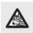
DANGER OF EXPLOSION!
Never recharge non-rechargeable batteries. Do not short-circuit batteries/rechargeable batteries and/or open them. Overheating, fire or bursting can be the result.
■ Never throw batteries/rechargeable batteries into fire or water.
- Do not exert mechanical loads to batteries/rechargeable batteries.
Risk of leakage of batteries/rechargeable batteries
- Avoid extreme environmental conditions and temperatures, which could affect batteries/rechargeable batteries, e.g. radiators/direct sunlight.
If batteries/rechargeable batteries have leaked, avoid contact with skin, eyes and mucous membranes with the chemicals! Flush immediately the affected areas with fresh water and seek medical attention!

WEAR PROTECTIVE GLOVES!
Leaked or damaged batteries/rechargeable batteries can cause burns on contact with the skin. Wear suitable protective gloves at all times if such an event occurs.
In the event of a leakage of batteries/rechargeable batteries, immediately remove them from the product to prevent damage.
- Only use the same type of batteries/rechargeable batteries. Do not mix used and new batteries/rechargeable batteries.
■ Remove batteries/rechargeable batteries if the product will not be used for a longer period.
Risk of damage of the product
■ Only use the specified type of battery/rechargeable battery!
- Insert batteries/rechargeable batteries according to polarity marks (+) and (−) on the battery/rechargeable battery and the product.
Use a dry lint-free cloth or cotton swab to clean the contacts on the battery/rechargeable battery and in the battery compartment before inserting!
■ Remove exhausted batteries/rechargeable batteries from the product immediately.
Notes for coin/button cell batteries

WARNING! Do not ingest the battery, chemical burn hazard.
This product contains coin/button cell batteries. If a coin/button cell battery is swallowed, it can cause severe internal burns in just 2 hours and can lead to death.

Keep new and used batteries away from children.
If the battery compartment does not close securely, stop using the product and keep it away from children.
If you think batteries might have been swallowed or placed inside any part of the body, seek immediate medical attention.
● Original accessories/auxiliary equipment
■ Use only the accessories and auxiliary equipment that are specified in this user manual and are compatible with the product.
Before first use
● Unpacking the product
- Take the product out of the packaging and remove all packaging materials and plastic wrappings.
- Check to make sure that all listed parts are included (see "Scope of delivery").
- Check whether the product and all parts are in good condition, if any damage or defect is detected, do not use the product, but follow the procedure described in chapter "Warranty".
● Preparation
- Inserting/changing the tool/collet chuck
- Press and hold the spindle lock button 11.
- Turn the clamping nut 8 until the lock clicks into place.
-
Loosen the clamping nut 8 from the thread using the combination spanner 21.
-
Remove any inserted tool, if necessary.
- Push the desired tool through the clamping nut 8.
- Insert the desired tool into the appropriate collet chuck 932 for the tool shaft.
- Press and hold the spindle lock button 11.
- Insert the collet chuck 932 into the thread insert.
- Tighten the clamping nut 8 on the thread using the combination spanner 21.
Using an accessory tool with a mandrel
☐ Insert the respective mandrel 24, 30 or 31 into the product (see “Inserting/ changing the tool/collet chuck”).
☐ Only for the mandrel for cutting/grinding discs 30:
- Loosen the screw on the mandrel for cutting/grinding discs 30 using the screwdriver side of the combination spanner 21.
- Insert the desired accessory tool between both washers on the screw.
-Tighten the screw on the mandrel for cutting/grinding discs 30.
Grindstone
☐ Regrind small edges by hand using the grindstone 20.
● Fitting an abrasive belt
- Slide the abrasive belt 26 onto the abrasive belt mandrel 24 from above.
- Fixing the abrasive belt 26 in place: Tighten the screw on the abrasive belt mandrel 24 using the screwdriver side of the combination spanner 21 .
● Fitting a polishing attachment
□ Screw the desired polishing attachment 36 onto the tip of the mandrel for polishing attachments 31.
Operation
- Setting the speed range
NOTE
Before switching on the product: Set the speed range.
The direction of rotation of the grinding spindle is indicated by the arrow engraved on the union nut 7.
☐ Set the speed control 2 to a position between 1 and MAX.
- Switching on and off
Switching on
□ Connect the mains plug 4 to a suitable socket-outlet.
☐ Set the on/off switch 3 to the I position.
Switching off
☐ Set the on/off switch 3 to the O position.
☐ Remove the mains plug 4 from the socket-outlet when you are not using the product.
● Using the grip ring with LED work light
NOTE
Before first use: Pull out the insulating strip 38 (Fig. D). The insulating strip prevents the button cells 40 from discharging.
- Loosen the union nut 7 in counterclockwise direction and remove it from the product. Store the union nut at a safe place.
- Screw the grip ring with LED work light 10 onto the thread in clockwise direction.
- Switching on the LED work light 10: Slide the on/off switch 37 to the I position (Fig. D).
- Switching off the LED work light 10: Slide the on/off switch 37 to the O position (Fig. D).
Notes on working with materials/tools/speed range
NOTE
The milling bit ^28 is not suitable for steel or iron. Suitable milling bits are available in stores.
☐ Use the milling bit 28 at maximum speed for working on wood, plastics and plasterboard.
☐ Determine the speed range for working on zinc, zinc alloys, aluminium, and copper by carrying out tests on test pieces.
☐ Use a low speed for working on plastics and materials with a low melting point.
☐ Use a medium speed for cleaning, polishing and buffing work.
☐ Use a high speed for working on wood.
NOTE
The following information is a non-binding recommendation. When carrying out practical work, test for yourself which tool and which settings are best suited to the material to be processed.
Setting a suitable speed
| Speed control 2 | Material to be processed |
| 1 Plastics and materials with a low melting point | |
| 2-3 Stone, ceramics | |
| 4 Soft wood, metal | |
| 5 Hard wood | |
| Max. Steel | |
Selecting suitable accessories for the appropriate speed

WARNING!
Do not exceed the specified maximum speed.
| Speed control 2 | Accessories Speed | |||
| MAX | — | — | □ Grinding bits 25□ Abrasive belts 26□ Milling bit 28□ Engraving bits 29□ Grinding discs 33□ Cutting discs 34 35 | 40,000 min-1 |
| 5 34,000 min | -1 | |||
| 4 28,000 min | -1 | |||
| 3 | □ Drill bit 27□ Polishing attachments 36 | 22,000 min-1 | ||
| 2 | □ Synthetic brushes 22□ Metal brush 23 | 16,000 min-1 | ||
| 1 10,000 min | -1 | |||
Application examples/selecting a suitable tool
| Function Accessories Use Protrusion | |||
| Drilling | Drill bit 27 | Processing wood | min. : 18 mmmax. : 25 mm |
| Milling | Milling bit 28 | Various jobs (e.g. creating recesses, hollows, moulds, grooves or slots) | min. : 18 mmmax. : 25 mm |
| Engraving | Engraving bits 29 | Labelling,handicrafts | min. : 18 mmmax. : 25 mm |
| * CAUTION! Exert only a light pressure when applying the tool to the workpiece. | |||
| Polishing, rust removal * | Metal brush 23 | Rust removal | min. : 9 mmmax. : 15 mm |
| Polishing attachments 36 | Processing various metals and plastics, especially precious metals such as gold and silver | min. : 12 mmmax. : 18 mm | |
| Cleaning | Synthetic brushes 22 | e.g. cleaning plastic housings that are difficult to access or cleaning the area around a door lock | min. : 9 mmmax. : 15 mm |
| Grinding | Grinding discs 33 | Grinding work on stone, wood, fine work on hard materials such as ceramics or alloyed steel | min. : 12 mmmax. : 18 mm |
| Grinding bits 25 | 10 mm | ||
| Abrasive belts 26 | 10 mm | ||
| Cutting | Cutting discs 34 35 | Processing metal, plastic and wood | min. : 12 mmmax. : 18 mm |
| * CAUTION! Exert only a light pressure when applying the tool to the workpiece. | |||
- Do not exceed the following maximum diameters:
| Max. ∅ Accessories | |
| 55 mm | □ Composite grinding bodies□ Grinding cones□ Mounted points with threaded inserts |
| 80 mm | □ Sandpaper grinding accessories |
The max. permissible length of a mandrel is 33 mm.
- Store the accessories in the original box or protect them against damage in a different way.
■ Store the accessories in a dry place away from any aggressive substances.
If you apply too much pressure, the clamped tool may break and/or the workpiece may be damaged. You can achieve optimum work results by guiding the tool towards the workpiece with a constant speed range and low pressure.
- When carrying out cutting work, hold the product firmly with both hands.
- Observe the data and information in above table to prevent the spindle end from touching the base of the hole in the grinding tool.
● Fitting/using the flexible shaft
⚠ NOTICE! Risk of product damage!
Do not press the spindle lock button 11 while the motor is running. Otherwise the product or the flexible shaft 16 may be damaged.
- Loosen the union nut 7 in counterclockwise direction and remove it from the product. Store the union nut at a safe place.
- Press and hold the spindle lock button 11.
- Loosen the clamping nut 8 in counter-clockwise direction and remove it from the product.
- Pull the shaft out a little so it can be fixed in the collet chuck 9.
- Fitting the flexible shaft 16 on the product: Insert the inner axle of the flexible shaft together with the clamping nut 8 into the collet chuck 9.
- Press and hold the spindle lock button 11.
- Tighten the clamping nut 8 using the combination spanner 21.
- Tighten the union nut 15 of the flexible shaft 16 on the product in clockwise direction.
- Place the desired accessory into the collet chuck 932 of the flexible shaft 16.
- Locking the spindle: Push the spindle lock 17 on the flexible shaft 16 backwards.
- Loosen the clamping nut 8 on the flexible shaft 16 using the combination spanner 21.
- Insert the accessory and retighten the clamping nut 8.
Stand
NOTE
You can mount the stand ^19 on a vertical or horizontal surface. The clamping device ^12 offers 2 positions for mounting the stand.
You can rotate the holde 18 by 360°.
(Fig. E)
- Screw the stand 19 into the clamping device 12.
- Screw the clamping device 12 to the edge of a workbench or worktable with a maximum thickness of 60 mm.
- Adjusting the height of the stand 19:
-Loosen the upper tube of the stand 19 by rotating it in counterclockwise direction.
–Pull out the tube to the desired height.
–Lock the tube by rotating it in clockwise direction.
- Adjusting the height of the holder 18:
-Rotate the black thread in counterclockwise direction.
-Set the holder 18 to the desired height.
-Tighten the thread by rotating it in clockwise direction.
- Fold the metal bracket 5 open.
- Hang the product with the metal bracket 5 on the hook of the holder 18.
Router cage
NOTE
The router cage ^14 makes the product particularly suitable for cutting out special shapes (e.g. holes for socket-outlets).
- Insert the milling bit 28 (see "Inserting/changing the tool/collet chuck").
The shaft of the milling bit 28 must protrude out of the collet chuck 9 by approx. 16 mm (Fig. F).
- Loosen the union nut 7 in counterclockwise direction and remove it from the product. Store the union nut at a safe place.
- Screw the router cage 14 onto the product.
- Setting the working depth (Fig. G):
- Loosen the locking screw 13.
- Set the foot of the router cage 14 to the desired position.
- Tighten the locking screw 13.
● Replacing the button cells
(Fig. H)
- Switch off the LED work light 10 (see "Using the grip ring with LED work light").
- Remove the grip ring with LED work light 10 from the product.
- Loosen the screws 39 and remove the top cover.
- Remove the old button cells 40 from the button cell holders 41.
- Insert 2 new button cells 40 into the button cell holders 41. The positive pole (+) must face upwards.
- Reassemble the grip ring with LED work light 10.
- Tighten the screws 39.
● Cleaning, maintenance and storage
⚠ WARNING! Risk of injury!

Before starting any work on the product: Switch off the product and unplug the mains plug 4.
If the supply cord is damaged, it must be replaced by the manufacturer, its service agent or similarly qualified persons in order to avoid a hazard.
☐ Have any repair and maintenance work that is not described in these instructions carried out by our Service Centre (see “Service”). Only use original replacement parts.
Cleaning
⚠ WARNING! Risk of electric shock!
▶ Never spray the product with water.
Do not immerse the product in water or other liquids
⚠ NOTICE! Risk of product damage!
Chemical substances may attack the plastic parts of the product. Do not use cleaning agents or solvents.
□ Keep the ventilation slots 6 and housing of the product clean. Use a damp cloth or brush to do this.
● Replacing the carbon brush
NOTE
Obtaining a new carbon brush: see "Replacement parts/Accessories"
(Fig. I)
- Open the carbon brush cover 1 using the narrow end of the combination spanner 21.
- Remove the old carbon brush.
- Place the new carbon brush into the cavity.
- Close the carbon brush cover 1 using the narrow end of the combination spanner 21.
Maintenance
☐ The product is maintenance free.
Storage
□ Always store the product and its accessories
-clean,
-dry,
-protected against dust,
-in the storage case,
-out of the reach of children.
● Replacement parts/Accessories
□ Customers can obtain compatible replacement parts and accessories via www.optimex-shop.com.
☐ You can only place orders online.
□ Contact the Lidl service hotline (see "Service") for further information.
- Disposal
The packaging is made entirely of recyclable materials, which you may dispose of at local recycling facilities.

Observe the marking of the packaging materials for waste separation, which are marked with abbreviations (a) and numbers (b) with following meaning: 1–7: plastics/20–22: paper and fibreboard/80–98: composite materials.
Product:
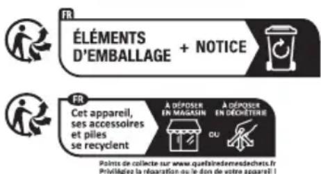
The product incl. accessories and packaging materials are recyclable and are subject to extended producer responsibility.
Dispose them separately, following the illustrated Info-tri (sorting information), for better waste treatment.
The Triman logo is valid in France only.

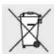
Contact your local refuse disposal authority for more details of how to dispose of your worn-out product.

To help protect the environment, please dispose of the product properly when it has reached the end of its useful life and not in the household waste. Information on collection points and their opening hours can be obtained from your local authority.
Faulty or used batteries/rechargeable batteries must be recycled. Return the batteries/rechargeable batteries and/or the product to the available collection points.
Environmental damage through incorrect disposal of the batteries/rechargeable batteries!
Remove the batteries/battery pack from the product before disposal.
Batteries/rechargeable batteries may not be disposed of with the usual domestic waste. They may contain toxic heavy metals and are subject to hazardous waste treatment rules and regulations. The chemical symbols for heavy metals are as follows: Cd = cadmium, Hg = mercury, Pb = lead. That is why you should dispose of used batteries/rechargeable batteries at a local collection point.
Warranty
The product has been manufactured to strict quality guidelines and meticulously examined before delivery. In the event of material or manufacturing defects
you have legal rights against the retailer of this product. Your legal rights are not limited in any way by our warranty detailed below.
The warranty for this product is 3 years from the date of purchase. The warranty period begins on the date of purchase. Keep the original sales receipt in a safe location as this document is required as proof of purchase.
Any damage or defects already present at the time of purchase must be reported without delay after unpacking the product.
Should the product show any fault in materials or manufacture within 3 years from the date of purchase, we will repair or replace it – at our choice – free of charge to you. The warranty period is not extended as a result of a claim being granted. This also applies to replaced and repaired parts.
This warranty becomes void if the product has been damaged, or used or maintained improperly.
The warranty covers material or manufacturing defects. This warranty does not cover product parts subject to normal wear and tear, thus considered consumables (e.g. batteries, rechargeable batteries, tubes, cartridges), nor damage to fragile parts, e.g. switches or glass parts.
● Warranty claim procedure
So that your request can be processed quickly, please observe the following instructions:
For all inquiries, please have the receipt and item number (IAN 471916_2407) ready as proof of purchase.
The article number can be taken from the identification label on the product, engraving on the product, the front cover of your manual (at the bottom left), or the sticker on the back or bottom of the product.
If malfunctions or other defects arise, first contact the service department indicated below by phone or email.
You can then send a product recorded as defective to the communicated service address postage-free, making sure to enclose proof of purchase (receipt) and information on the details of the defect and when it occurred.

You can download and view this and numerous other manuals at parkside-diy.com. This QR code takes you directly to parkside-diy.com. Choose your country and use the search screen to search for the operating instructions. Entering the item number (IAN) 471916_2407 takes you to the operating instructions for your item.
Service
GB Service Great Britain
Tel.: 0800 0569216
E-Mail: owim@lidl.co.uk
IE Service Ireland
Tel.: 1800 200736
E-Mail: owim@lidl.ie
● EU Declaration of conformity
EU DECLARATION OF CONFORMITY (No 471916\_2407)
IAN: 471916 2407
Product identification:
"PARKSIDE" Rotary Tool
Model Number: HG12438
The object of the declaration described above is in conformity with the relevant Union harmonisation legislation:
| Directive 2006/42/EC |
| Directive 2014/30/EU |
| Directive 2011/65/EU and all related amendments |
References to the relevant harmonised standards used or references to the other technical specifications in relation to which conformity is declared:
| N° / Parts |
| Directive 2006/42/EC |
| EN 60745-1:2009/A11:2010 |
| EN 60745-2-23:2013 |
| Directive 2014/30/EU |
| EN IEC 55014-1:2021 |
| EN IEC 55014-2:2021 |
| EN IEC 61000-3-2:2019/A1:2021 |
| EN 61000-3-3:2013/A2:2021 |
The object of the declaration described above is in conformity with Directive 2011/65/EU of the European Parliament and of the Council of 8 June 2011 on the restriction of the use of certain hazardous substances in electrical and electronic equipment:
| N° / Parts |
| EN IEC 63000:2018 |
Keeper of the technical documentation: OWIM GmbH & Co.KG
Signed for and on behalf of:
This declaration of conformity is issued under the sole responsibility of the manufacturer.
Translation of the original declaration of conformity
Neckarsulm 21. Okt
Place
Date

Authorised Signatory Authorised Signatory
EN

Dongguan Tianqiu Enterprise Co., Ltd., Tianqiu Industrial Park, Xinji Industrial Zone, Machong Town, Dongguan, Guangdong, R.P.C. Chine