
PPBS 3 A1 - Lawn mower PARKSIDE - Free user manual and instructions
Find the device manual for free PPBS 3 A1 PARKSIDE in PDF.

| Product type | Gasoline brushcutter with electric start |
| Brand | Parkside |
| Model | PPBS 3 A1 |
| Engine | 2-stroke engine, displacement 51.7 cm³ |
| Max. engine power | 1.45 kW (1.9 HP) |
| Idle speed | 3000 min⁻¹ |
| Max. engine speed | 9500 min⁻¹ |
| Cutting speed | 7800 min⁻¹ (steel knife 3 blades/clearing blade 22 teeth) 7800 min⁻¹ (spool of line, radius 430 mm) |
| Fuel tank capacity | 1200 cm³ (1.20 l) |
| Fuel mixture ratio | 40:1 (gasoline:2-stroke oil) |
| Weight (without fuel) | 6.2 kg |
| Weight (engine unit) | 6.98 kg |
| Cutting radius (spool of line) | 430 mm |
| Cutting radius (steel knife 3 blades) | 255 mm |
| Cutting radius (clearing blade 22 teeth) | 200 mm |
| Sound pressure level (LpA) | 102.5 dB(A) ; KpA = 3 dB |
| Guaranteed sound power level (LWA) | 114 dB(A) |
| Vibrations (multifunction handle) | 7.354 m/s² ; K=1.5 m/s² |
| Vibrations (handle) | 7.785 m/s² ; K=1.5 m/s² |
| Compatible battery | X 20 V TEAM (PAP 20 B1, PAP 20 B3, Smart PAPS 204 A1, Smart PAPS 208 A1) |
| Compatible charger | PLG 20 A1, PLG 20 A3, PLG 20 A4, PLG 20 C1, PLG 20 C2, PLG 20 C3, PLG 201 A1, PDSLG 20 A1, PDSLG 20 B1, Smart PLGS 2012 A1 |
| Intended use | Mowing grass, edges, around trees/posts, bushes; clearing blade for undergrowth and stumps up to 20 mm in diameter |
| Warranty | 5 years (conditions in manual) |
Frequently Asked Questions - PPBS 3 A1 PARKSIDE
User questions about PPBS 3 A1 PARKSIDE
0 question about this device. Answer the ones you know or ask your own.
Ask a new question about this device
Download the instructions for your Lawn mower in PDF format for free! Find your manual PPBS 3 A1 - PARKSIDE and take your electronic device back in hand. On this page are published all the documents necessary for the use of your device. PPBS 3 A1 by PARKSIDE.
USER MANUAL PPBS 3 A1 PARKSIDE
Petrol Brush Cutter with Electric Ignition Translation of the original instructions
NL BE
Before reading, unfold the page containing the illustrations and familiarise yourself with all functions of the device.
FR BE
Scope of delivery/accessories. 40
Overview. 40
Description of functions. 42
Technical data. 42
Safety information. 44
Meaning of the safety information. 44
Pictograms and symbols. 44
General safety instructions. 45
Additional safety rules. 47
Residual risks. 48
Protective measures against kickback. 48
Safety devices. 49
Assembly 49
Mounting the protective cover. 49
Fitting the two-piece handle..... 49
Fitting the handlebar. 50
Fitting the spool cap. 50
Fitting the carabiner. 50
Preparation. 50
Mixing and filling fuel. 50
Fitting 3-blade steel cutter. 51
Fitting the 22-tooth clearing blade. 51
Putting on the double shoulder strap. 52
Checking the battery charge level. 52
Charging the battery. 52
Inserting and removing the battery. 52
Working instructions. 53
Operation. 53
Before use. 53
Removing/mounting the protective cover extension.....54
Adjusting the carrying harness eyelet/balancing out the device. 54
Working with the spool. 54
Extending the line. 55
Working with a metal cutting tool. 55
If the device vibrates. 55
Checking the clutch. 55
Start the engine. 55
Cleaning, maintenance and storage. 57
Cleaning. 57
Maintenance. 57
Storage. 61
Troubleshooting 62
Transport 63
Transport 63
Disposal/environmental protection. 63
Service. 64
Guarantee. 64
Repair service. 66
Service Centre. 66
Importer. 66
Spare parts and accessories.....66
Translation of the original EU declaration of conformity. 67
Exploded view. 357
Introduction
Congratulations on purchasing your new petrol scythe (hereinafter referred to as product or device).
You have chosen a high-quality device. This device was quality-tested and subjected to a final inspection during production, therefore ensuring proper functioning of your device.
In some cases, residual amounts of lubricants may be present on or in the device. This is not a flaw or a defect and is no cause for concern.


The instruction manual forms part of this device. It contains important information on safety, use and disposal. Read the instruction manual carefully. Familiarise yourself with the controls and how to use the device correctly. Use the device only as described and for the stated fields of application. Store the instruction manual carefully and ensure that all documents are handed over in the event that the device is passed on to another user.
Proper use
This device is only intended for the following uses: For mowing work
- on grass in gardens
along the edges of flower beds
around trees or fence posts - in light undergrowth
The clearing blade can be used to cut thickets and small logs up to 20mm in diameter.
The device is intended for use by adults. Children under the age of 16 may not use the device, except under supervision.
Any other use that is not expressly permitted in this instruction manual may pose a serious hazard to the user and result in damage to the device. The operator or user of the machine is responsible for any accidents or personal injury and/or material damage to third parties or their property. The machine is intended to be used by do-it-yourselfers. It was not designed for heavy commercial use. The warranty is void in the case of commercial use. The manufacturer is not liable for damage caused by improper use or incorrect operation.
Scope of delivery/accessories
Unpack the device and check that everything is present.
Dispose of the packaging material properly.
-
Petrol Brush Cutter with Electric Ignition
-
Engine housing with upper shaft tube
- Handlebar
-
Lower shaft tube
Spool
3-blade steel cutter
22-tooth clearing blade -
2 × Transport protection
- 2 × Protective cover
- Double shoulder strap with body protection
Combination tool - 2 × Hex key (4 mm & 5 mm)
Assembly materials - Fuel mixing bottle (500 ml)
- Accessories bag
- Rechargeable battery and charger with instruction manual
- Original instructions
Overview
Fig. A
1 Spark plug connector
2 Starter handle
3 Battery holder
4 Electric starter
5 Fuel tank
6 Tank cover
7 Fuel pump
8 Cold start lever (choke)
9 Screw
10 Air filter cover
11 Cable holder
12 Device cord
13 Star screw
14 Handlebar
15 Handle
16 Lower shaft tube
17 Protective cover
18 Locking mechanism
19 22-tooth clearing blade
20 Tube mounting screw
21 Upper shaft tube
22 Multifunction handle
23 Eyelet
24 Off button
25 Throttle lock
26 Throttle lever
27 Protective cover
28 Protective cover extension
29 3-blade steel cutter
30 Spool cap
31 Transport protection
32 Transport protection
33 Combination tool
34 Hex key (4 mm)
35 Hex key (5 mm)
36 Fuel mixing bottle
37 Battery
38 Button (Charge level indicator)
39 Charge level indicator
40 Battery release
41 Charger
42 Double shoulder strap
43 Click fastener
44 Hip protector
45 Carabiner
46 Nut
47 Clamping disk
48 Washer
49 Accessories bag
Fig. B
50 Screw
51 Shaft mount
52 Screw
Fig. C
53 Lock
Fig. D
54 Handle mount
55 Holder
Fig. E
56 Tool holder
57 Line cutter
Fig.J
58 Lock
Fig. K
59 Wing screw
Fig. M
60 Lock
61 Spool
62 Line outlet loop
63 Recess
Fig. N
64 Air filter
65 Air filter housing
Fig. O
66 Spark plug
Fig. P
67 Fuel filter
Fig. Q
68 Notch
69 Groove
Fig. R
70 Screw
Description of functions
The hand-held and portable petrol scythe is powered by a combustion engine that runs continuously during operation. The power is transmitted via a clutch disc, which uses a high-revolution centrifugal clutch to transfer the engine output to the cutting unit.
As a cutting device, the scythe has a dual-line spool which is equipped with an auto-tap feed. During the cutting process, two plastic lines rotate around an axis vertical to the cutting plane.
As an alternative to the dual-line spool, the 3-blade steel blade or the 22-tooth clearing blade can be fitted.
Technical data
Petrol Brush Cutter with Electric Ignition .PPBS 3 A1
Engine 2-stroke engine
Displacement 51.7 cm3
Max. engine power .. 1.45 kW (1.9 PS)
Engine speed
-Idling n0 3000 min
-Max. engine speed .9500 min
Cutting speed
-with 3-blade steel cutter/22-tooth clearing blade .7800 min
-with spool; 430 mm .... 7800 min-1
Tank volume 1200 cm³ (1.20 l)
Fuel mixing ratio 40:1
Emission level V
Carbon dioxide emission value (CO_2) determined by an EU type approval procedure: 1063 g/kWh
Engine manufacturer
Trade name: WUYANG
- Company name: Zhejiang Wu Yang Industry & Trade Co., Ltd.
- Contact address in the Union: Rake Forester GmbH, Andre-Citroen-Str. 18, D51149 Cologne, Germany Weight
-Weight (without tank content) .6.2 kg
-Weight (engine unit) 6.98 kg
Line - Cutting circle 430 mm
-Line thickness 2.4 mm
-Line length 6 m
3-blade steel cutter/22-tooth clearing blade - Cutting circle 255 mm
-Thickness 1.4 mm
Hole 25.4 mm
-Max. permitted speed ... 10000 min-1 22-tooth clearing blade - Cutting circle 200 mm
-Thickness 1.5 mm
Hole 25.4 mm
-Max. permitted speed ... 10000 min ^-1 Sound pressure level ( L_pA )
102.5 dB; K_pA = 3 dB Sound power level (L_WA) - Guaranteed 114 dB
- Measured ....111.6 dB; K_WA = 2.1 dB Vibration (a_h)
- Multifunction handle 7.354 m/s²; K=1.5 m/s²
- Handle ......... 7.785 m/s²; K=1.5 m/s²
Levels of noise and vibration were determined according to the standards and regulations in the declaration of conformity.
The specified total vibration value was determined according to the following standard: ISO 22867
The specified noise emission values were determined in accordance with the following standard: ISO 22868
The values have been determined according to a standardised test pro
cedure and can be used to compare one tool with another. The specified total vibration value and the stated specified noise emission value can also be used for a provisional assessment of the load.
WARNING! The vibration and noise emissions may deviate from the specified values during actual use of the device, depending on how the device is being used. Safety measures for the protection of the operator are to be determined that are based on an estimate of the actual vibration load under the real operating conditions (for this, all parts of the operating cycle are to be taken into account, for example, times in which the device is turned off, and those during which it is turned on but running without a load).
X 20 V TEAM
The device is part of the
X 20 V TEAM series and can be
operated with batteries of the X 20 V TEAM series. Batteries of the X 20 V TEAM series may only be charged using chargers of the X 20 V TEAM series.
We recommend that you operate this appliance with the following batteries only: PAP 20 B1, PAP 20 B3, Smart PAPS 204 A1, Smart PAPS 208 A1
Use of the device with the following batteries is prohibited: Smart PAPS 2012 A1
We recommend charging these batteries with the following chargers: PLG 20 A1, PLG 20 A3, PLG 20 A4, PLG 20 C1, PLG 20 C2, PLG 20 C3, PLG 201 A1, PDSLG 20 A1, PDSLG 20 B1, Smart PLGS 2012 A1 Rechargeable battery and charger technical data: See separate manual.
| Charging time (min.) | PAP 20 A1 PAP 20 A2 PAP 20 B1 | PAP 20 A3 PAP 20 B3 Smart PAPS 204 A1 | Smart PAPS 208 A1 |
| PLG 20 A1 PLG 20 A4 PLG 20 C1 | 60 120 240 | ||
| PLG 20 C2 45 80 165 | |||
| PLG 20 A2 PLG 20 A3 PLG 20 C3 PDSLG 20 A1 PDSLG 20 B1 | 35 60 120 | ||
| PLG 201 A1 135 250 500 | |||
| Smart PLGS 2012 A1 | 35 45 50 |
Safety information
This section deals with the basic safety instructions for using the device.
WARNING! Injury and property damage due to improper handling of battery. Observe the safety information and notes on charging and proper use as shown in the instruction manual for your battery and charger from the series X 20 V TEAM. A detailed description of the charging process and further information can be found in these separate operating instructions.
Meaning of the safety information
DANGER! If you do not observe this safety instruction, an accident will occur. The result of which is severe bodily injury or death.
WARNING! If you do not observe this safety instruction, an accident may occur. The result of which is likely severe bodily injury or death.
CAUTION! If you do not observe this safety instruction, an accident will occur. The result of which is likely minor or moderate bodily injury. NOTICE! If you do not observe this safety instruction, an accident will occur. The result of which is possible damage to property.
Pictograms and symbols Symbols on the device

Attention!

Read the instruction manual

Use eye protection

Use head protection

Use hearing protection

Use protective gloves

Wear safety shoes with firm soles!

Beware of ejected parts keep bystanders away

Attention! Kickback - be aware that you may experience kickback while working with the machine.

Caution! Hot surfaces, burn risk!

Guaranteed sound power level L_WA in dB(A)

Direction of movement by cutting unit

For use with a spool

For use with 3-blade steel cutters

Open flames, fire, open ignition sources and smoking are prohibited.

Mixing ratio fuel to 2-stroke oil: 40:1, ONLY use fuel mixture

ONLY use fuel mixture

Maintain a safe distance of at least 15m from other people

Operate the cold start lever (choke)

Press the fuel pump

Pull the starter cord or actuate the electric starter

Operate the throttle lock and throttle lever
General safety instructions
Access by children as well as sick and frail people is to be prevented. Children must be carefully supervised when in the vicinity of machinery. Observe the regional and local accident prevention regulations applicable to your location. The same applies to all provisions on occupational health and safety at work.
The manufacturer cannot be held liable if its machines are modified without authorisation and if such changes result in damage to people or property.
WARNING! Basic precautionary measures are to always be taken when using machines. Please also observe all tips and notices in the additional safety instructions.
-
Pay attention to the environmental conditions in which you are working. The engine produces toxic exhaust fumes as soon as it is running. These gases can be odourless and invisible. You must therefore never work with the device in closed or poorly ventilated rooms. Ensure that there is sufficient lighting during the work. Make sure you have a secure footing in wet conditions, snow, ice, on slopes and on uneven terrain.
-
Do not let third parties access the device. Visitors and observers, especially children and sick and frail people must be kept away from the work area. Prevent other people from coming into con
tact with the tools. Only pass the device on to people who are familiar with the device and its handling.
-
Ensure tools are stored securely. Tools that are not in use must be stored in a dry, preferably high location, or locked away out of access.
-
Always use the right tool for every job. For example, do not use small tools or accessories for work that actually has to be done with heavy-duty tools. Use tools only for the purposes for which they were designed.
-
Ensure you wear suitable clothing. The clothing must be fit for purpose and must not hinder you when you are working. Wear clothing with cut resistant inserts.
-
Use personal protective equipment. Wear safety shoes with steel toecaps/steel soles and nonslip soles. Wear a safety helmet if the work entails a risk of falling objects.
-
Wear safety goggles. Objects may be thrown towards you. This may result in severe eye injuries.
-
Wear ear protection. Wear personal hearing protection, e.g. ear plug.
-
Hand protection Wear sturdy gloves - leather gloves provide good protection.
-
Operating the device Never work without the appropriate protective cover. Risk of injury due to ejected objects.
-
Remove all socket wrenches etc. All wrenches/keys and similar must be removed before switching on the device.
-
Always remain attentive. Pay attention to what you are do
ing. Use common sense. Do not use any motorised tools when you are tired. You may not operate the device under the influence of alcohol, medication or drugs that impair your ability to react.
13. Filling up with fuel
- Always comply with the applicable fire protection regulations and the relevant state/federal regulations on fire prevention.
- Fuel and fuel vapours are very inflammable. Do not fill with fuel when the engine is running or still hot. Make sure there is good ventilation when filling with fuel. Smoking and open fires are prohibited.
- Always switch off the engine before filling. Always open the fuel filler cap carefully so that any excess pressure can be released slowly and no fuel sprays out. Working with the device generates high temperatures on the housing. Therefore, allow the device to cool down before filling. Otherwise the fuel could ignite and cause serious burns.
- When filling with fuel, make sure that you do not overfill. If liquid is spilt, remove it immediately and clean the device.
After filling, ensure that the screw plug is securely fastened to prevent loosening due to the vibrations generated during work. - Watch out for leaks. If fuel is leaking, do not start the engine. Danger to life due to burns!
14. Duration of use and breaks
Prolonged use of the device can lead to blood circulation disorders in the hands caused by vibration (Raynaud's syndrome). However,
you can extend the duration of use by wearing suitable gloves or taking regular breaks. Please ensure that if you are susceptible to poor circulation, low outside temperatures or strong gripping forces while working, this may reduce the length of time for which you are able to work.
15.Look out for damaged parts. If the device suffers a heavy impact or is dropped, check it for signs of damage and wear before putting it back into operation. Are individual parts damaged? In the case of slight damage, carefully reflect on whether the tool will still work properly and safely. Ensure moving parts are correctly aligned and set up. Are the parts interlocking properly? Are parts damaged? Is everything correctly installed? Are all other requirements for proper functioning met? Damaged safety equipment etc. must be properly repaired or replaced by authorised persons, unless otherwise indicated in the instruction manual. Defective switches must be replaced by an authorised entity. If repairs are need, contact a customer service centre authorised by us.
-
Always switch the engine off before making adjustments or maintenance work. This especially applies to any work on the spool.
-
Only use approved parts. Only use identical spare parts for maintenance and repairs. Spare parts are available from our online shop (see Spare parts and accessories, p. 66).
WARNING! The use of other mower heads as well as accessories and attachments that are not ex
pressly recommended can endanger people and property. The tool may only be used for the intended purpose. Any use other than for the intended purpose is considered improper use. The user is solely responsible for property damage and personal injury resulting from such improper use; the manufacturer bears no liability under any such circumstance. The manufacturer cannot be held liable if its machines are modified or used improperly and if this results in damage to people or property.
Additional safety rules To prevent personal injury and damage to property:
- Attention! Always keep your hands and feet away from the cutting area, especially when starting the device. Always keep your hand free on the auxiliary handle.
- Always hold the device with your hands on both handles. Always keep the device at a suitable safety distance from the body and maintain a stable body posture.
- Always wear safety goggles.
- Only use the device in daylight or where there is good artificial lighting.
- Do not use the device in the rain or on wet grass.
- Check the device for damage before use or after an impact, and repair if necessary.
- Do not use the device if the safety equipment is damaged or incorrectly installed.
- Ensure that the ventilation slits on the engine, the protective cover and cutting unit are always free of dirt or residual material.
- During the work process, always ensure that there are no people or
animals within a radius of at least 15m . Switch off the device immediately if anyone, especially children, comes within reach of the machine. When using the device, stones and other objects can be ejected, which may lead to serious injuries.
- When the device is in operation, do not get near to the moving parts (within the cutting unit area). The cutting head will keep rotating for a few seconds after the device has been switched off.
11.Before using the device, stones, twigs and any other solid material must be removed from the work area. Only start the machine as described in the manual. It must not be upside down when starting or in the working position. Do not cross any gravel roads or paths with the device running. - Extreme caution is required when extending the cutting line. There is a risk of cutting injuries. After performing these steps, the device must be brought back into the correct working position before being re-started.
- Do not use any metallic cutting spools. Note that the device will continue to operate for a few seconds after you let go of the switch.
- Switch off the engine when:
filling the device with fuel,
not using it,
- leaving it unattended,
- cleaning it,
- transporting it from one location to another,
- Removing or replacing the cutting unit or adjusting the length of the cutting line by hand.
- Prolonged use of the device can lead to hearing damage if appropriate hearing protection is not worn. Wear personal hearing protection, e.g. ear plugs, to reduce the risk of hearing damage.
- Carry the device by the upper and lower shaft tube when it is switched off, with the cutting unit pointing away from your body in order to avoid injuries. After switching off, the motor head of the device is hot. Make sure that you do not come into contact with the motor head.
- Regularly check whether the cutting equipment is at a standstill when idling.
- National regulations may specify an age restriction for the user.
-
Be aware that the following circumstances can lead to damage to the device and serious injuries to the person operating it:
-
improper maintenance,
- use of non-compliant spare parts,
-
the removal or modification of safety devices.
-
Attention! Local regulations may restrict use of the machine.
-
Always maintain the device and cutting tool in a good condition.
22.Before use, check the device for loose fastenings, fuel leaks and damaged parts, such as cracks in the cutting attachments. - Take breaks and change your working position regularly.
- Warning! There are sharp edges on the string trimmer. Gloves need to be worn.
- In order to detect significant defects, a visual inspection needs to be performed before each use,
after the device is dropped or if it suffers any kind of impact.
- Wear both non-slip foot protection and protective clothing when using the string trimmer.
27.Never use the machine if you are tired,ill or under the influence of alcohol or other drugs. - Warning of exhaust emissions!
- Assume a firm stance and maintain your balance during operation. Also use the carrying strap provided.
Residual risks
There will always be residual risks even if you operate this device according to the instructions. The following hazards may occur in connection with the type and design of this device:
- Eye damage if no suitable eye protection is worn.
- Lung damage if suitable respiratory protection is not worn.
- Hearing damage if suitable ear protection is not worn.
Cutting injuries
WARNING! Danger due to electromagnetic field generated while the tool is in operation. Under certain circumstances, this field may negatively affect active or passive medical implants. In order to reduce the danger of serious or fatal injuries, we recommend that individuals who wear medical implants should consult their doctor and the manufacturer of the implant before operating the tool.
Protective measures against kickback
WARNING! Risk of injury! In the event of a kickback, the operator will feel a powerful blow from the device.
Loss of control of the device and serious injuries. Avoid kickback through caution and correct technique. When using a metal cutting tool, there is a risk of kickback if the cutting edge hits an obstacle (e.g. stone, wood).
-
Hold the device firmly with both hands.
-
Make sure there are no obstacles on the ground.
-
Do not use a metal cutting tool near fences, metal posts or similar.
-
Only use properly sharpened metal cutting tools.
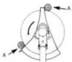
To cut thick stems, switch the device to position A.
Safety devices
The following safety devices are provided to protect the user and the device:
Protective cover (17/27)
- Protects the operator from unintentional contact with the cutting tools and from injury by ejected foreign objects.
Throttle lock (25)
- Prevents accidental acceleration of the engine. The throttle lever (26) can only be operated when the throttle lock is pressed.
Transport protection (31/32)
- Covers the cutting edges of the cutting tool or clearing blade during transport or storage.
Quick opening mechanism: Click fastener (43)
- Enables the operator to escape quickly from the device in an emergency.
Assembly
Mounting the protective cover
WARNING! Risk of injury! Never use the device without the protective cover properly mounted.
Fitting the protective cover for 3blade steel cutter/spool (Fig. B) 1
- Position the black protective cover (27) for the 3-blade steel blade/ spool on the shaft mount (51).
- Screw the 4 screws (50) into the protective cover (27) for the 3-blade steel blade/spool using the (smaller) 4mm hex key (34).
Removing the protective cover for 3-blade steel cutter/spool (Fig. B)
- Loosen the 4 screws (50) using the (smaller) 4mm hex key (34).
- Remove the protective cover (27) for the 3-blade cutter/spool.
Fitting the protective cover for the 22-tooth clearing blade (Fig. B)
- Position the silver protective cover (17) for the 22-tooth grinder blade on the cutting head.
- Screw the 3 screws (52) into the protective cover (17) for the 22-tooth clearing blade using the (smaller) 4mm hex key (34).
Removing the protective cover for the 22-tooth clearing blade (Fig. B)
- Loosen the 3 screws (52) using the (smaller) 4mm hex key (34).
- Remove the protective cover (17).
Fitting the two-piece handle
Assembly (Fig. C)
-
Loosen the shaft tube mounting screw (20) on the upper shaft tube (21).
-
Push the lower shaft tube (16) as far as possible into the upper shaft tube (21).
- Push the lock (53) and slide the lower shaft tube (16) as far as it goes into the upper shaft tube (21).
- Turn the lower shaft tube (16) with a gentle rotating movement until the lock (53) clicks into place in the hole on the upper shaft tube (21).
- Tighten the shaft tube mounting screw (20) back into place by hand.
NOTICE! Before you start the device, make sure that the lower shaft tube is firmly and securely in place and located in the correct position.
Disassembly (Fig. C)
- Loosen the tube mounting screw (20).
- Push the lock (53).
- Pull the shaft tubes apart.
Fitting the handlebar
Procedure (Fig. D)
- Loosen the star screw (13) and remove the handle mount (54) from the upper shaft tube (21).
- Insert the handlebar (14) into the holder (55) on the upper shaft tube (21). The plastic ring on the handlebar (14) must sit in the guide rail in the holder (55).
- Attach the handlebar (14) to the handle mount (54) and star screw (13). Tighten the star screw (13) hand-tight.
- Secure the device cord with the cable holders (11).
Fitting the spool cap
WARNING! The black protective cover must be fully fitted when using the spool (Removing/mounting the protective cover extension, p. 54).
Procedure (Fig. E)
- Press the locking mechanism (18) to block the tool holder (56).
- Screw the spool cap (30) onto the tool holder (56).
- Pull on both ends of the line to release the lines from the grooves.
- Trim the line string to approx. 15 cm to release strain on the engine when starting and warming up.
NOTICE! The washer (48), clamping disk (47) and nut (46) are not required for mounting the spool.
Fitting the carabiner
Notes
- Leave the carabiner fitted. Detach the device from the double shoulder strap using the click fastener.
- The eyelet can be moved. This allows you to balance the device.
Procedure
- Open the click fastener (43).
- Attach the short piece of strap to the eyelet (45) using the carabiner (23).
Preparation
WARNING! Risk of injury due to unintentional start-up. Only insert the rechargeable battery into the device once the device is fully prepared for use.Do not start the motor until the device is fully prepared for use.
Mixing and filling fuel
DANGER! Risk of fire or explosion! Always ensure good ventilation when handling fuel. Do not smoke while refuelling and keep any heat sources at a distance. Never refuel while the engine is running. Carefully open the fuel filler cap so that any overpressure
can slowly dissipate. Start the device at a distance of at least 3m from the fuelling point.
CAUTION! Use only the fuel mixture recommended in the instructions. The fuel mixture ages. Therefore, do not use fuel mixtures that are older than 3 months (E10: 30 days). If this not done, the engine may become damaged and your warranty will become null and void.
WARNING! Danger to health!
Avoid direct skin contact with petrol and inhalation of petrol fumes.
NOTICE! Unsuitable fuel can damage the two-stroke engine. Only operate the device with a mixture of petrol and two-stroke engine oil at a ratio of 40:1.
| Petrol 2-stroke oil | |
| 40 parts 1 part | |
| 1 L 25 ml | |
| 3 L 75 ml | |
| 5 L 125 ml |
Notes
Tank volume (Fuel): 1200cm^3 (1.20 l)
- For optimal performance, use oil for air-cooled two-stroke engines.
Mixing fuel (Fig. H)
The fuel mixing bottle (36) features a scale that indicates the mixing ratio for one tank filling.
- First fill petrol into the fuel mixing bottle (36) up to the mark PETROL.
- Pour in two-stroke engine oil adding it to the petrol up to the mark OIL.
- Close and shake the fuel mixing bottle (36).
Filling fuel (Fig. H)
-
Place the device on its side with the fuel cap (6) facing upwards.
-
Unscrew the fuel cap (6).
- Pour the fuel mixture into the fuel tank (5).
- Wipe off any fuel residue around the fuel cap (6).
- Close the fuel cap (6).
Fitting 3-blade steel cutter
CAUTION! The black protective cover must be shortened when using the 3-blade steel cutter (Removing/ mounting the protective cover extension, p. 54).
Procedure (Fig. F)
- Press the locking mechanism (18) to block the tool holder (56).
- Place the 3-blade steel cutter (29) on the tool holder (56). The blade can be used on both sides.
- Secure the 3-blade steel cutter with the washer (48), clamping disk (47) and nut (46). The combination tool (46) can be used to tighten the nut (33).
Fitting the 22-tooth clearing blade
CAUTION! The silver protective cover must be fitted when using the 22-tooth clearing blade (Mounting the protective cover, p. 49).
Procedure (Fig. G)
- Press the locking mechanism (18) to block the tool holder (56).
- Place the 22-tooth clearing blade (19) on the tool holder (56). The inscription on the blade must be visible to the user during use!
- Secure the 22-tooth clearing blade with the washer (48), clamping disk (47) and nut (46). The combination tool (46) can be used to tighten the nut (33).
Putting on the double shoulder strap
DANGER! Risk of accident! Always wear the double shoulder strap when working with the device. Always switch off the device before taking off the double shoulder strap.
NOTICE! The double shoulder strap is equipped with a quick release device. Opening the click fastener (43) releases the device quickly from the double shoulder strap in a dangerous situation.
Requirements
- The carabiner (45) is attached to the eyelet with part of the click fastener (43).
Procedure (Fig. I)
- Put the double shoulder strap (42) on.
- Adjust the strap length so that the click fastener (43) is at hip height.
- Attach the device to the double shoulder strap (42): Close the click fastener (43).
- Place the hip protector (44) on your hip between your body and the device.
Checking the battery charge level
LEDs Meaning
red, orange, green Battery charged red, orange Battery partially charged
red Battery needs to be charged
-
Press the button (38) next to the charge level indicator button (39) on the battery (37). The LEDs of the charge level indicator show how much charge remains in the battery.
-
Charge the battery (37) when only the red LED on the charge level indicator (39) is illuminated.
Charging the battery
See also the charger instruction manual.
Notes
- If warm, allow the battery to cool before charging.
- Do not expose the battery to direct sunlight for long periods and do not place it on a radiator (max. 50^ ).
Charging the battery
- Remove the battery (37) from the device.
- Push the battery (37) into the charging slot of the battery charger (41).
- Connect the battery charger (41) to a power outlet.
- After charging, disconnect the battery charger (41) from the mains.
- Pull the battery (37) out of the battery charger (41).
Inserting and removing the battery
WARNING! Risk of injury due to unintentional start-up. Only insert the rechargeable battery into the device once the device is fully prepared for use.
NOTICE! Risk of damage! An incorrect battery can damage the device and battery.
Inserting the battery
- Push the battery (37) along the guide into the battery holder (3). You will hear the battery click into place.
Removing the battery
-
Press and hold the battery release (40) on the battery (37).
-
Pull the battery out of the battery holder (3).
Working instructions
Work safely, giving due consideration to the next steps!
-
When strimming, pay attention to country-specific regulations and/or those of your local municipality.
-
Do not do strimming work during general rest periods.
Solid items such as stones, metal parts and similar are to be removed. These can be ejected and lead to personal injury and damage to property.
- When strimming high bushes or hedges, the working height should be at least 15cm . This means that animals like hedgehogs are not put at risk.
Always hold the device tightly and securely with both hands!
- Only cut grass and weeds with the spool and steel cutter! A clearing blade can be used to cut thickets and small logs up to 20mm in diameter. Watch out for roots or tree stumps, there is a risk of tripping.
Work carefully and do not endanger anyone while you are strimming.
-
You should only work in good lighting conditions with sufficient visibility!
-
Keep an eye on the cutting head!
-
Never trim above shoulder height!
-
Never replace the plastic cord with a steel wire - risk of injury and damage!
-
Never work on a ladder!
-
Only work on firm and stable surfaces!
-
Avoid an abnormal body posture. Ensure that your footing is secure and keep your balance at all times.
-
Change your working position at regular intervals in order to prevent becoming tired on one side of your body.
- If the cutting head is blocked: Switch off the device, wait until all moving parts have come to a complete standstill and remove the spark plug connector. Then remove the blocking.
Operation
Before use
WARNING! Before putting the device into operation, you must check it for operational safety. If you have any doubts, do not start the device!
NOTICE! Remove the protective film from the line cutter before using the device for the first time (57). Pay particular attention to the following points:
- Check the cutting tools for damage and wear.
- Correct assembly of the cutting head.
- Smooth operation of all switches.
- Secure fit of the spark plug connector. If the plug is loose, sparks can occur and ignite the escaping fuel/air mixture.
- Correct function of the clutch.
- Clean handles for safe handling of the device.
- All safety and protective devices must be properly installed and in place before the device can be started.
The cutting head must be able to move freely. Before starting the device, make sure that the cutting head is correctly positioned and that the moving parts are free.
WARNING! If you have any doubts, ask a specialist at an authorised service centre to help you operate this device.
Removing/mounting the protective cover extension
The protective cover extension must be removed when using the 3-blade steel cutter.
The protective cover extension must be attached if using the spool.
Tools and aids required
- Slotted screwdriver
Removing the protective cover extension (Fig. J)
- Unlock the lock of the protective cover extension (58) using a slotted screwdriver.
- Pull off the protective cover extension (28).
Fitting the protective cover extension (Fig. J)
- Insert the lugs of the lock (58) into the tabs on the protective cover (27).
- Press the protective cover extension (28) firmly until the lugs engage in the tabs.
- Check the lock (58) and the tight fit of the protective cover extension (28).
NOTICE! Clean the extension and protective cover of the device after each use.
Adjusting the carrying harness eyelet/balancing out the device
Select the correct position for the carrying harness eyelet according to whether you are using a spool or blade.
Requirements (Fig. K)
The scythe attached to the harness should be used without touching it with your hand,
The spool should rest lightly on the ground.
The blade should be balanced around 20 cm above the ground.
Procedure (Fig. K)
- Loosen the screw (59) on the eyelet (23) for the double shoulder strap. Use the 4 mm hex key (34) for this. Slightly tighten the screw again.
- Depending on the cutting tool, balance the scythe according to the above criteria by moving the eyelet (23) on the upper shaft tube (21).
- Tighten the screw (59) when the scythe is in the desired position.
Working with the spool
In small grass areas hold the device at an angle of about 30^ and swing the cutting head evenly to the right and left with a semi-circular movement.
- The best results are obtained with a maximum grass length of 15cm . If the grass is taller, it is recommended to mow several times.
- To cut around trees, fence posts or other obstacles, slowly move the device around the obstacle and cut with the line ends.
- Avoid any contact with fixed obstacles (e.g. rocks, walls, picket fences, etc.). The line would wear out quickly. Use the edge of the protective cover to keep the device at the correct distance.
CAUTION! Do not lay the cutting head on the ground during operation!
Extending the line
Your device is equipped with a dual-line auto-tap feature, i.e. the two strings are extended when you tap the cutting head on the ground.
Procedure
- Hold the device in operation over a grassy area and lightly tap the cutting head a few times on the ground. This causes the line to lengthen.
- The line cutter (27) installed in the black protective cover (57) cuts off the thread to the desired length.
If the thread ends can not be lengthened:
- Switch off the device.
- Press the spool insert as far as it will go and pull firmly on the end of the string.
If no line ends are visible:
- Replace the spool (see Spool damage, p. 58).
CAUTION! Risk of injury! Thread remnants can be projected and lead to injuries.
Working with a metal cutting tool
WARNING! Risk of injury! Always wear the harness and suitable protection clothing when working with the device. Wear eye, hearing and head protection. Ensure that the metal cutting tool is installed correctly. Replace damaged or blunt tool parts.
NOTICE! Only use the cutting blade to work on open, even areas. Carefully inspect the area to be cut and remove all foreign bodies. Avoid hitting stones, metal or other obstacles. The metal cutting tool can be damaged and there is a risk of kickback by the device.
- When working, hold the cutting head above the ground and swivel the device back and forth like a scythe in an equal arch.
- Do not hold the cutting head at an angle.
- Do not use the device to cut wild growth or brushwood.
- Check the metal cutting tool regularly for damage and replace a damaged metal cutting tool.
If the device vibrates
Clean the device and remove any grass residue in the cutting head and protective cover (see Cleaning, maintenance and storage, p. 57).
Checking the clutch
NOTICE! Place the device on a firm level surface. Make sure that the cutting tool does not touch either other objects or the ground.
Before each use, check that the clutch is working correctly when idle. Start the device (see Start the engine, p. 55) and carry out a visual inspection at a sufficiently safe distance to verify that the cutting unit does not rotate during idle.
Start the engine
The device can also be operated without a battery if you start the device with the starter cord.
Before starting the engine
DANGER! Start the engine at least 3 m away from where you refuelled. NOTICE! Place the device on a firm level surface. Make sure that the cutting tool does not touch either other objects or the ground.
When using the spool (Fig. E)
- Fit the black protective cover (27) with protective cover extension
(28). Remove the protective cover on the line cutter (57).
When using the 3-blade steel cutter (Fig. F)
- Fit the black protective cover (27) without protective cover extension (28).
When using the 22-tooth clearing blade (Fig. G)
- Fit the silver protective cover (17).
Cold start
Starting with the starter rope (Fig. L)
- Place the device on a firm level surface. Make sure that the cutting tool does not touch either other objects or the ground.
- Set the cold start lever (choke) (8) to position .
- Press the fuel pump (7) 6 times.
- Hold the device firmly with one hand by the upper shaft tube (21). With the other hand, pull the starter rope on the starter handle (2) quickly several times in succession until the engine starts. Attention! Do not pull the starter rope out too far - Danger of breakage!
NOTICE! If the device does not start after pulling the rope 3-4 times, set the cold start lever (choke) manually to position:
- Press the throttle lock (25) and then the throttle lever (26) briefly to enable the cold start lever (choke) (8) to move to position . The device begins to idle. Allow the device to warm up at idle for between 45 seconds and 1:30 minutes.
-
To mow, keep the throttle lock (25) pressed down and operate the throttle lever26).
-
To switch off the engine, briefly press the Off button (24).
NOTICE! If the engine has not started after two attempts, try a warm start without the choke in the warm start position. If this is not successful, follow the instructions in section Troubleshooting, p. 62.
Starting with the electric start (Fig. L)
- Place the device on a firm level surface. Make sure that the cutting tool does not touch either other objects or the ground.
- Set the cold start lever (choke) (8) to position .
- Press the fuel pump (7) 6 times.
- Insert the battery (37).
- Fold up the cover and actuate the electric starter (4). NOTICE! If the device does not start after actuating the electric starter 3-4 times, set the cold start lever (choke) manually to position:
- Press the throttle lock (25) and then the throttle lever (26) briefly to enable the cold start lever (choke) (8) to move to position The device begins to idle. Allow the device to warm up at idle for between 45 seconds and 1:30 minutes.
- To mow, keep the throttle lock (25) pressed down and operate the throttle lever26).
- To switch off the engine, briefly press the Off button (24).
NOTICE! If the engine has not started after two attempts, try a warm start without the choke in the warm start position. If this is not successful, follow the instructions in section Troubleshooting, p. 62.
Warm start
Starting with the starter rope (Fig. L)
-
Leave the cold start lever (choke) (8) in its position
-
Hold the device firmly with one hand by the upper shaft tube (21). With the other hand, pull the starter rope on the starter handle (2) quickly several times in succession until the engine starts.
Attention! Do not pull the starter rope out too far - Danger of breakage!
The device is now idle.
- To mow, keep the throttle lock (25) pressed down and operate the throttle lever26).
- To switch off the engine, briefly press the Off button (24).
Starting with the electric start (Fig. L)
- Leave the cold start lever (choke) (8) in its position
- Insert the battery (37).
- Fold up the cover and actuate the electric starter (4). The device is now idle.
- To mow, keep the throttle lock (25) pressed down and operate the throttle lever26).
- To switch off the engine, briefly press the Off button (24).
Cleaning, maintenance and storage
WARNING! Electric shock! Risk of injury due to unintentional start-up.
Maintenance and cleaning work must always be carried out with the engine switched off and the spark plug connector (1) removed.
You should have any repair and maintenance work that is not described in these instructions carried out by our Service Centre. Only use original spare parts and never use metallic lines.
The use of non-original parts can cause personal injury and irreparable damage to the device and will immediately invalidate the warranty.
Cleaning
- Clean the cutting unit and the protective cover of grass and soil each time after cutting.
- Keep the handles clean and free of grass.
- Clean the device with a soft brush or a cloth.
- Protect the device from damage. The device must neither be sprayed with water nor be put into water.
- Do not use any cleaning agents or solvents.
Maintenance
Service intervals
Carefully perform the maintenance tasks listed in the following table on a regular basis. Regular servicing of your device will extend its life. Additionally, you will achieve optimum cutting performance and prevent accidents.
| Machine part Action Before | each use | After 10 hours of use | After 20 hours of use | |
| Screws, nuts, bolts | Check and tighten | ✓ | ||
| Air filter (64) Cleaning the air filter, p. 59 | ✓ | |||
| Spark plug (66) Checking/adjusting/ replacing spark plug, p. 60 | ✓ | |||
| Fuel filter (67) Visual inspection, replace as needed | ✓ | |||
| Fuel hoses Visual inspection, replace as needed | ✓ | |||
| Complete machine | Visual inspection, clean as needed | ✓ | ||
| Operating handle | Check for function✓ | |||
| Cutting head Check correct installation✓ | ||||
| Coupling Check that the device is stationary while idle | ✓ | |||
| Gears Lubricating the gears, p. 61 | ✓ | |||
Spool damage
WARNING! The protective cover must be fully mounted when using the spool (see Removing/mounting the protective cover extension, p. 54).
- Switch off the engine.
- Place the device on the ground in a stable position and ensure that no fuel escapes.
(Fig. E):
- Press the locking mechanism (18) to block the tool holder (56).
- Unscrew the spool cap (30) from the tool holder (56). (Fig. M):
- Open the spool cap (30) by pressing the lock (60) on both sides of the spool cap (30) firmly inwards and remove the cover of the spool
cap. A slotted screwdriver can be used to assist in opening the spool cap.
Proceed with caution: do not damage the spool.
-
Place the new spool (61) in the spool cap cover (30) and insert the two ends of the line through the line outlet loop (62).
-
Place the spool (61) in the spool cap cover (30) and allow the cover to latch back into the spool cap (30).
Ensure that the line outlet loops (62) match the two recesses (63) in the spool cap otherwise the cover will not close.
(Fig. E):
-
Press the locking mechanism (18) to block the tool holder (56).
-
Screw the spool cap (30) onto the tool holder (56).
10.Pull on both ends of the line to release the lines from the grooves.
11.Trim the line string to approx. 15 cm to release strain on the engine when starting and warming up.
Changing blades
CAUTION! Cutting injuries! Wear cut-resistant gloves to avoid injury.
Changing the 3-blade steel cutter
CAUTION! The black protective cover must be shortened when using the 3-blade steel cutter (Removing/ mounting the protective cover extension, p. 54).
- Switch off the engine.
- Place the device on the ground in a stable position and ensure that no fuel escapes. (Fig. F):
- Press the locking mechanism (18) to block the tool holder (56).
- Loosen the nut (46). Remove the clamping disk (47), washer (48) and 3-blade steel cutter (29).
- Place the new 3-blade steel cutter (29) on the tool holder (56) or turn over the old 3-blade steel cutter (29). The blade can be used on both sides.
- Secure the 3-blade steel cutter with the washer (48), clamping disk (47) and nut (46). The combination tool (46) can be used to tighten the nut (33).
Changing the 22-tooth clearing blade
CAUTION! The silver protective cover must be fitted when using the 22-tooth clearing blade (Mounting the protective cover, p. 49).
- Switch off the engine.
- Place the device on the ground in a stable position and ensure that no fuel escapes.
(Fig. G):
- Press the locking mechanism (18) to block the tool holder (56).
- Loosen the nut (46). Remove the clamping disk (47), washer (48) and 22-tooth clearing blade (19).
- Place the new 22-tooth clearing blade (19) on the tool holder (56). The inscription on the blade must be visible to the user during use.
- Secure the 22-tooth clearing blade with the washer (48), clamping disk (47) and nut (46). The combination tool (46) can be used to tighten the nut (33).
Cleaning the air filter
CAUTION! Never run the device without an air filter. Dust and dirt may otherwise enter the engine and cause damage to the machine. Keep the air filter clean.
Procedure (Fig. N)
- Switch off the engine and let the device cool down.
- Loosen the screw (9) on the air filter cover (10).
- Remove the air filter cover (10) from the air filter housing (65).
- Remove the air filter (64).
- Clean the air filter (64) with water and allow it to air dry. Never use petrol for cleaning!
NOTICE! Replace the air filter (64) if it is worn, damaged or dirty (Spare parts and accessories, p. 66).
NOTICE! The grid acts as a spacer and has to be inserted in the air filter housing (65) first, if it falls out when removing the air filter (64).
- Put the air filter (64) back in.
- Insert the two lugs on the air filter cover (10) into the tabs on the air filter housing (65).
- Fold the air filter cover (10) onto the air filter housing (65).
- Fix the air filter cover again with the screw (9).
Checking/adjusting/replacing spark plug
CAUTION! Worn spark plugs, or a spark plug gap that is too large, will lead to a reduction in engine power. Ensure that the spark plugs are in perfect condition.
Tools and aids required
- Feeler gauge (available from specialist dealers)
- Wire brush
- Spare spark plug
Procedure (Fig. O)
- Switch off the engine and let the device cool down.
- Pull the spark plug connector (1) from the spark plug (66).
- Screw out the spark plug (66) with the enclosed combination tool (33)
-
You can now check, adjust and clean the spark plug:
-
Use a feeler gauge to check whether the electrode gap has the following value: 0.6 - 0.7 ~mm
- Reset the gap if necessary: Carefully bend the ground electrode of the spark plug (66).
- Clean the spark plug (66) with a wire brush.
-
If you cannot bring the spark plug into perfect condition: Replace the spark plug.
-
Screw in the spark plug (66) with the combination tool (33)
-
Plug the spark plug connector (1) back onto the spark plug (66).
Sharpening the line cutter
WARNING! Risk of injury! Never use the device with a defective line cutter. Replacement line cutters are available from our online shop (Spare parts and accessories, p. 66).
CAUTION! Cutting injuries! Wear cut-resistant gloves to avoid injury.
Tools and aids required
Vice
- Flat file
Procedure (Fig. E)
- Switch off the engine and let the device cool down.
- Unscrew the line cutter (57) from the black protective cover (27).
- Clamp the line cutter (57) in a vice and sharpen the blade with a flat file. File carefully, and always in one direction only.
- Screw the line cutter (57) back onto the protective cover (27).
Replacing the fuel filter
Never run the device without a fuel filter. Change the fuel filter regularly.
Procedure (Fig. P)
- Unscrew the fuel cap (6).
- Empty the fuel tank (5) into a suitable vessel.
- Pull the fuel filter (67) out of the tank using a hook and remove it by loosening the small clamp.
- Replace the fuel filter (67) and place the attached suction knob back in the tank.
- Close the fuel tank (5) again with the tank cap (6).
Fuel filter specifications:
- Connection 4mm
- Outside diameter: approx. 16 mm
Winding up the spool
As an alternative to a new spool, you can purchase a 2.4 mm-thick, 6 m-long nylon line in specialist shops and wind this yourself onto the spool.
Procedure (Fig. Q)
- Fold the line in the middle and place the middle of the line in the notch (68) of the spool (61).
- Wind the two ends in the direction indicated by the arrow on the underside of the spool.
- Then clamp the end of each line in one of the grooves (69) on the spool (61).
NOTICE! Pull the lines tight and ensure that they are parallel in the two line channels. In addition, the spool must not be filled with more than 3m of line in each channel, as otherwise the automatic line mechanism will not function correctly.
Lubricating the gears
Lubricate the gears about every 10 operating hours.
Tools and aids required
- Hex key, 5 mm (35)
- Multi-purpose grease
Procedure (Fig. R)
- Remove the screw (70) on the gears.
- Press approx. 5g of grease into the lubrication opening on the gear housing.
- Close the gears again using the screw (70).
Adjusting the carburettor
The carburettor has been preconfigured for ideal performance at the factory. If any readjustments are necessary, have the adjustments made by a specialist workshop.
Removing blockages
WARNING! Risk of injury! Switch the device off and remove the spark plug connector (1) before you work on the cutting unit.
CAUTION! Cutting injuries! Wear cut-resistant gloves to avoid injury.
Storage
General storage instructions
- Clean and maintain the device and accessories carefully before storage.
- Store the device in a dry and dust-proof location and out of reach of children.
- Do not wrap the device in plastic bags as moisture and mildew may form.
- Do not lie the device down on the protective cover.
- Use transport protection (31/32) when storing the blades.
- The cable holders (11) should hold the device cord (12) in position. Do not remove the cable holders, even when storing the device.
Storage when not in operation
CAUTION! Fuel residues in the carburettor can cause starting problems or permanent damage to the device.
For operational breaks of up to 3 months
- Empty the fuel tank (5) in a well-ventilated place.
- Start the engine, allowing it to idle until the engine stops and the carburettor is free of fuel.
- Let the engine cool off (about 5 minutes).
Further measures for breaks in operation of more than 3 months
-
Remove the spark plug (66) with the combination tool (33) (Checking/adjusting/replacing spark plug, p. 60).
-
Fill a teaspoon with pure 2-stroke oil into the combustion chamber.
- Pull the starter cord slowly several times to distribute the oil inside the engine.
- Put the spark plug (66) back in.
Troubleshooting
The following table will assist you in fixing faults:
| Problem Possible cause | Error correction | |
| Engine will not start | No fuel in the tank Mixing and filling fuel, p. 50 | |
| Incorrect starting sequence | Start the engine, p. 55 | |
| Engine is "flooded" Let off | throttle, start engine several times, remove, clean and dry the spark plug if necessary | |
| Sooty spark plugs, incorrect ignition gap | Checking/adjusting/ replacing spark plug, p. 60 | |
| Spark plug connection or ignition cable defective | Replace | |
| Carburettor, carburettor jets dirty, incorrect carburettor mix setting | Adjusting the carburettor, p. 61 | |
| Clogged fuel filter Replacing the fuel filter, p. 60 | ||
| Battery (37) is empty or not inserted | Charge the battery (see the separate operating instructions for the re-chargeable battery and charger) | |
| Engine runs too fast at idle | Engine cold Warm up slowly | |
| Engine will not run at expected maximum power | Sooty spark plugs, incorrect ignition gap | Checking/adjusting/replacing spark plug,p. 60 |
| Dirty air filter (64) Cleaning | the air filter,p. 59 | |
| Carburettor, carburettor jets dirty, incorrect carburettor mix setting | Adjusting the carburettor,p. 61 | |
| Incorrect fuel mixture Mixing | ng and filling fuel,p. 50 | |
| Sealing ring in crankcase leaking | Have the fault rectified by a specialist workshop | |
| Cylinder, piston rings worn | ||
| Incorrect ignition | ||
| Excessive formation of exhaust fumes/smoke | Incorrectly set carburettor mixture | Adjusting the carburettor,p. 61 |
| Incorrect fuel mixture Mixing and filling fuel,p. 50 | ||
Transport
Transport
- During transport, the device must be switched off and the spark plug connector (1) must be disconnected. Do not transport the device when it is idling.
- Carry the device with one hand on the upper shaft tube (21) and the other hand on the lower shaft tube (16) in order to avoid coming into contact with dangerous parts when transporting it (e.g. hot engine, cutting unit).
- Use the transport protection (31, 32) when transporting the blades.
- Keep a safe distance from other people during transport.
-
Do not transport the device upside down, as otherwise fuel might leak out.
-
Before transporting between two locations, do not empty the petrol tank indoors, near a fire or while smoking. Gas vapours can cause explosions or fire.
- Transporting in a vehicle: Secure the device against tipping over and damage. Ensure the device is securely positioned.
Disposal/ environmental protection
Dispose of the tool in accordance with the local regulations. For further information, please contact your local administration.
- Do not dispose of waste oil and petrol residues in the sewage system or down the drain. Dispose of waste oil and petrol remnants in an
environmentally friendly way - take them to your local recycling centre.
- The tool, accessories and packaging should be properly recycled.
- Machines must not be disposed of with domestic waste.
- Empty the oil and fuel tanks carefully and return your tool to a recycling centre.
- Dispose of empty oil and fuel containers in an environmentally friendly manner.
- The plastic and metal parts used on your tool can be properly sorted according to materials and grades and efficiently recycled.
If you have any other questions, contact the service centre.
Remove the battery from the device and recycle the device, battery, accessories and packaging in an environmentally-friendly manner.

Electrical devices must not be disposed of with domestic waste.
The symbol of the crossed-out wheeled bin means that this product must not be disposed of as unsorted municipal waste at the end of its useful life.
Directive 2012/19/EU on waste electrical and electronic equipment:
Consumers are legally obliged to recycle electrical and electronic equipment in an environmentally sound manner at the end of its life. In this way, environmentally friendly and resource-saving recycling is ensured. Depending on the implementation in national law, you may have the following options:
-
Return to a shop,
-
Hand over to an official collection point,
- Return to the manufacturer/distribu-tor.
This does not affect accessories enclosed with the old devices or tools without any electrical components.
Service
Guarantee
Dear Customer,
This product is provided with a 5 year guarantee from the date of purchase. In case of defects, you have statutory rights against the seller of the product. These statutory rights are not restricted by our guarantee presented below.
Terms of Guarantee
The guarantee period begins on the date of purchase. Please retain the original receipt. This document is required as proof of purchase. If a material or manufacturing defect occurs within five years of the date of purchase of this product, we will repair or replace - at our choice - the product for you free of charge. This guarantee requires the defective product and proof of purchase to be presented within the five-year period with a brief written description of what constitutes the defect and when it occurred. If the defect is covered by our guarantee, you will receive either the repaired product or a new product. No new guarantee period begins on repair or replacement of the product.
Guarantee Period and Statutory Claims for Defects
The guarantee period is not extended by the guarantee service. This also applies for replaced or repaired parts. Any damages and defects
already present at the time of purchase must be reported immediately after unpacking. Repairs arising after expiry of the guarantee period are chargeable.
Guarantee Cover
The product has been carefully produced in accordance with strict quality guidelines and conscientiously checked prior to delivery.
The guarantee applies for all material and manufacturing defects. This guarantee does not extend to cover product parts that are subject to normal wear and may therefore be considered as wearing parts (e.g. Spool, Air filter und Spark plug) or to cover damage to breakable parts (e.g. Switch).
This guarantee shall be invalid if the product has been damaged, used incorrectly or not maintained. Precise adherence to all of the instructions specified in the operating manual is required for proper use of the product. Intended uses and actions against which the operating manual advises or warns must be categorically avoided.
The product is designed only for private and not commercial use. The guarantee will be invalidated in case of misuse or improper handling, use of force, or interventions not undertaken by our authorised service branch.
Processing in Case of Guarantee
To ensure efficient handling of your query, please follow the directions below:
-
Please have the receipt and product number (IAN 466547_2404) ready as proof of purchase for all enquiries.
-
Please refer for the product number to the type plate on the
product, an engraving on the product, the title page of the operating instructions (bottom left) or the sticker on the back or underside of the product.
- Should functional errors or other defects occur, please initially contact the service centre specified below by telephone or use the contact form available on parkside-diy.com in the category Service.
- After consultation with our customer service, a product recorded as defective can be sent postage paid to the service address communicated to you, with the proof of purchase (receipt) and specification of what constitutes the defect and when it occurred. In order to avoid acceptance problems and additional costs, please be sure to use only the address communicated to you. Ensure that the consignment is not sent carriage forward or by bulky goods, express or other special freight. Please send the appliance inc. all accessories supplied at the time of purchase and ensure adequate, safe transport packaging.

You can view and download these and many other manuals on parksidediy.com. This QR code will take you
directly to parkside-diy.com. Select your country and search for the operating instructions via the search mask. You can open your operating instructions by entering the article number (IAN) 466547_2404.
Repair service
For repairs that are not covered by warranty, contact the service centre. They will gladly create a cost estimate for you.
We can only work on devices which are sent in properly packed and with postage paid.
Note: Please send your device cleaned and with an indication of the defect to the address named for the service centre.
-
The following are not accepted: devices sent in without prepaid postage, sent as bulky goods, sent as an Express shipment, or devices sent as any other form of special freight.
-
We will dispose of defective devices you ship to us free of charge.
Service Centre
GB Service Great Britain Tel.: 0800 051 8970
Contact form on
parkside-diy.com
IAN 466547 2404
MT Service Malta Tel.: 800 65168
Contact form on
parkside-diy.com
IAN 466547 2404
Importer
Please note that the address below is not a service address. Contact the service centre named above first.
Spare parts and accessories
You can get spare parts and accessories from www.grizzlytools.shop. If you have any problems with your order, contact us via our online shop. If you have any other questions, contact: Service Centre, p. 66
| Pos. nr. | Name Order No. | |
| 27, 28 Set (Protective cover, Line cutter) 91110593 | ||
| 30 Spool cap 91105679 | ||
| 29 3-blade steel cutter 13800233 | ||
| 19 22-tooth clearing blade 91110595 | ||
| 32 Transport protection (22-tooth clearing blade) 91110594 | ||
| 64 Air filter 91110584 | ||
| 66 Spark plug 91110578 | ||
Translation of the original EU declaration of conformity
Product: Petrol Brush Cutter with Electric Ignition
Model:PPBS3A1
Serial number: 000001-015000
The object of the declaration described above is in conformity with the relevant Union harmonisation legislation:
2006/42/EC • 2014/30/EU • 2000/14/EC & 2005/88/EC (EU) 2016/1628 & (EU) 2018/989 • 2011/65/EU & (EU) 2015/863
The object of the declaration described above is in conformity with Directive 2011/65/EU of the European Parliament and of the Council of 8 June 2011 on the restriction of the use of certain hazardous substances in electrical and electronic equipment.
To ensure conformity, the following harmonised standards and national standards and regulations have been applied:
EN ISO 11806-1:2022 • EN ISO 14982:2009 • EN IEC 63000:2018
In accordance with the Directive 2000/14/EC relating to noise emission, the following is confirmed: Sound power level (L_WA)
Measured: 111.6 dB;
Guaranteed: 114 dB
Followed conformity assessment procedure according to 2000/14/EC, Annex V. This declaration of conformity is issued under the sole responsibility of the manufacturer:

Authorised representative of documentation
Sommaire
Introduction. 68
Reparatie-service. 133
Service-Center. 133
Importeur. 133
54 Handgreepklem
55 Houser
Fig. E
D51149 Cologne, Germany
Peso
Reparationservice. 352
Service-Center 353
Importor. 353
OBS! Varme overflader, fare for forbstranding!
Garanteret lydefektniveau L_WA i dB(A)

Skaereenhedens Ioberetning

Rengoring at luftfilter
FORSIGTIG! Anvend aldrig apparatet Eden luftfilter. I modsat fald slipper stov og snavs ind i motoren og medforer skader pa maskinen. Hold luftfilteret rent.
Opbevaring under driftspauser

- FR BE
- Safety information. 44
- Assembly 49
- Preparation. 50
- Operation. 53
- Cleaning, maintenance and storage. 57
- Troubleshooting 62
- Transport 63
- Disposal/environmental protection. 63
- Service. 64
- Spare parts and accessories.....66
- Translation of the original EU declaration of conformity. 67
- Introduction
- Proper use
- Scope of delivery/accessories
- Overview
- Fig. A
- Fig. B
- Fig. C
- Fig. D
- Fig. E
- Fig.J
- Fig. K
- Fig. M
- Fig. N
- Fig. O
- Fig. P
- Fig. Q
- Fig. R
- Description of functions
- Technical data
- Petrol Brush Cutter with Electric Ignition .PPBS 3 A1
- Engine manufacturer
- X 20 V TEAM
- Safety information
- Meaning of the safety information
- Pictograms and symbols Symbols on the device
- General safety instructions
- Filling up with fuel
- Duration of use and breaks
- Additional safety rules To prevent personal injury and damage to property:
- Residual risks
- Protective measures against kickback
- Safety devices
- Protective cover (17/27)
- Throttle lock (25)
- Transport protection (31/32)
- Quick opening mechanism: Click fastener (43)
- Assembly
- Mounting the protective cover
- Fitting the protective cover for 3blade steel cutter/spool (Fig. B) 1
- Removing the protective cover for 3-blade steel cutter/spool (Fig. B)
- Fitting the protective cover for the 22-tooth clearing blade (Fig. B)
- Removing the protective cover for the 22-tooth clearing blade (Fig. B)
- Fitting the two-piece handle
- Assembly (Fig. C)
- Disassembly (Fig. C)
- Fitting the handlebar
- Procedure (Fig. D)
- Fitting the spool cap
- Procedure (Fig. E)
- Fitting the carabiner
- Notes
- Procedure
- Preparation
- Mixing and filling fuel
- Mixing fuel (Fig. H)
- Filling fuel (Fig. H)
- Fitting 3-blade steel cutter
- Procedure (Fig. F)
- Fitting the 22-tooth clearing blade
- Procedure (Fig. G)
- Putting on the double shoulder strap
- Requirements
- Procedure (Fig. I)
- Checking the battery charge level
- LEDs Meaning
- Charging the battery
- Inserting and removing the battery
- Inserting the battery
- Removing the battery
- Working instructions
- Operation
- Before use
- Removing/mounting the protective cover extension
- Tools and aids required
- Removing the protective cover extension (Fig. J)
- Fitting the protective cover extension (Fig. J)
- Adjusting the carrying harness eyelet/balancing out the device
- Requirements (Fig. K)
- Procedure (Fig. K)
- Working with the spool
- Extending the line
- If the thread ends can not be lengthened:
- If no line ends are visible:
- Working with a metal cutting tool
- If the device vibrates
- Checking the clutch
- Start the engine
- Before starting the engine
- When using the spool (Fig. E)
- When using the 3-blade steel cutter (Fig. F)
- When using the 22-tooth clearing blade (Fig. G)
- Cold start
- Starting with the starter rope (Fig. L)
- Starting with the electric start (Fig. L)
- Warm start
- Attention! Do not pull the starter rope out too far - Danger of breakage!
- Cleaning, maintenance and storage
- Cleaning
- Maintenance
- Service intervals
- Spool damage
- (Fig. E):
- Changing blades
- Changing the 3-blade steel cutter
- Changing the 22-tooth clearing blade
- (Fig. G):
- Cleaning the air filter
- Procedure (Fig. N)
- Checking/adjusting/replacing spark plug
- Procedure (Fig. O)
- Sharpening the line cutter
- Replacing the fuel filter
- Procedure (Fig. P)
- Fuel filter specifications:
- Winding up the spool
- Procedure (Fig. Q)
- Lubricating the gears
- Procedure (Fig. R)
- Adjusting the carburettor
- Removing blockages
- Storage
- General storage instructions
- Storage when not in operation
- For operational breaks of up to 3 months
- Further measures for breaks in operation of more than 3 months
- Troubleshooting
- Transport
- Disposal/ environmental protection
- Directive 2012/19/EU on waste electrical and electronic equipment:
- Service
- Guarantee
- Terms of Guarantee
- Guarantee Period and Statutory Claims for Defects
- Guarantee Cover
- Processing in Case of Guarantee
- Repair service
- Service Centre
- Importer
- Spare parts and accessories
- Translation of the original EU declaration of conformity
- Sommaire
- Rengoring at luftfilter
- Opbevaring under driftspauser
Brand : PARKSIDE
Model : PPBS 3 A1
Category : Lawn mower