
LWF AR 1.5 - Air-conditioner STIEBEL ELTRON - Free user manual and instructions
Find the device manual for free LWF AR 1.5 STIEBEL ELTRON in PDF.

| Product type | Water/Air air conditioner |
| Brand | Stiebel Eltron |
| Model | LWF AR 1.5 |
| Cooling capacity | 1.55 kW |
| Heating capacity | 3.4 kW |
| Max. airflow rate | 420 m³/h |
| Operating range | -30 to 45 °C |
| Air duct connection | 180 mm |
| Heat source circuit connection | 22 mm |
| Condensate drain | 19 mm |
| Dimensions (H x W x D) | 500 x 600 x 512 mm |
| Weight | 11 kg |
| Protection class | IP22 |
| Installation | Wall or ceiling mounting |
| Use | Heating or cooling of fresh air |
| Compatibility | Heat pump or heat generator with centralized ventilation |
| Recommended filter | ISO Coarse 65% |
| Heat exchanger cleaning | Every 6 months |
| Condensate drain check | Monthly |
| Heat transfer fluid | Water only |
| Warranty | Varies by country |
Frequently Asked Questions - LWF AR 1.5 STIEBEL ELTRON
User questions about LWF AR 1.5 STIEBEL ELTRON
0 question about this device. Answer the ones you know or ask your own.
Ask a new question about this device
Download the instructions for your Air-conditioner in PDF format for free! Find your manual LWF AR 1.5 - STIEBEL ELTRON and take your electronic device back in hand. On this page are published all the documents necessary for the use of your device. LWF AR 1.5 by STIEBEL ELTRON.
USER MANUAL LWF AR 1.5 STIEBEL ELTRON
natural_image
Black cube-shaped object with a circular vent and ventilation grille (no text or symbols visible)natural_image
Four technical line drawings of a rectangular electronic component with internal parallel slots, shown without any text or symbols.natural_image
Technical line drawing of a mechanical assembly with two clamps and a base plate (no text or symbols)natural_image
Technical line drawing of a mechanical housing or enclosure with internal components and mounting holes (no text or symbols)natural_image
Technical line drawing of a heat exchanger or cooling unit with pipe and heating elements (no text or symbols)1.1 Units of measurement 12
1.2 Test mark.... 12
2 Safety.... 12
2.1 Structure of the warning notices....12
2.2 Intended use 12
2.3 Foreseeable misuse.... 12
2.4 Safety instructions.... 12
3 Product description 12
3.1 Standard delivery 12
3.2 Required accessories.... 13
3.3 Optional accessories.... 13
4 Installation (qualified contractors).... 13
4.1 Transportation (qualified contractors).... 13
4.2 Installation site.... 13
4.3 Profile rails 13
4.4 Mounting the appliance 14
4.5 Connecting the condensate hose 14
4.6 Connecting air ducts.... 15
4.7 Filter 15
4.8 Connecting the heat source circuit.... 15
4.9 Filling the heat source circuit ....15
4.10 Completing the installation.... 16
5 Cleaning 16
6 Cleaning (qualified contractors) 16
7 Maintenance .... 16
7.1 Filter 16
7.2 Checking the condensate drain.... 17
8 Troubleshooting.... 17
9 Specification 17
9.1 Dimensions and connections ..... 17
9.2 Pressure drop 17
9.3 Data table 18
10 Guarantee.... 18
11 Environment and recycling.... 18
1 General information

Read these instructions carefully before using the appliance and retain them for future reference.
1.1 Units of measurement
All measurements are given in mm unless stated otherwise.
1.2 Test mark
See type plate on the appliance.
2 Safety
2.1 Structure of the warning notices
2.1.1 Section-specific warning notices
Section-specific warning notices apply to all steps in the section.
Injury
CAUTION

Type and source of risk
Consequence(s) of failure to observe the warning notice
▶ Hazard prevention measure(s)
Property damage, consequential losses, environmental pollution
NOTICE

Type and source of risk
Consequence(s) of failure to observe the warning notice
▶ Hazard prevention measure(s)
2.1.2 Embedded warning notices
Embedded warning notices apply only to the step immediately following the notice.
▶ SIGNAL WORD: Consequence(s) of failure to observe the warning notice. Hazard prevention measure(s). Step to which the warning notice refers
2.1.3 Key to symbols
Symbol Type of risk

Injury

Electrocution

Burns, scalding
2.1.4 Signal words
Signal word Meaning
DANGER Failure to observe this information will result in death or serious injury.
WARNING Failure to observe this information may result in death or serious injury.
CAUTION Failure to observe this information may result in moderate or minor injury.
Signal word Meaning
NOTICE Failure to observe this information may result in property damage, consequential losses or environmental damage.
2.2 Intended use
The appliance is designed for heating or cooling supply air. The appliance is combined with a central ventilation unit and any heating heat pump or with an air source heat pump with integral central ventilation unit. The appliance is built into the supply air duct. The appliance is connected to the heat generator. Only water is permissible as a heat transfer medium in the heat source circuit. Only air is permissible as a medium in the air duct.
The product is designed for domestic use. This product can also be used in a non-domestic environment, e.g. in a small business, as long as it is used in the same way.
Observation of these instructions and of instructions for any accessories used is also part of the intended use of this appliance.
2.3 Foreseeable misuse
The product is not designed for installation outdoors.
Any other use beyond that described shall be deemed to be outside the intended use.
2.4 Safety instructions
Injury
- Only qualified contractors are permitted to carry out installation, commissioning, maintenance and repair work.
Property damage, consequential losses, environmental pollution
- Unsuitable spare parts and accessories may jeopardise user and product safety. Only use original spare parts and original accessories.
- Safe use is not guaranteed if installation of the appliance is incomplete. The appliance should only be operated once it is fully installed and all safety equipment has been fitted.
- Subjecting the appliance to weight loads or pressure may damage the casing or cause the appliance to fall off. Never place any objects on top of the appliance.
3 Product description
A heat transfer medium flows inside the heat exchanger.
The heat transfer medium can be heating water, for example.
The temperature of the air flowing through the product and the temperature of the heat transfer medium converge.
In the winter, the heat transfer medium releases heat to the air.
If the heat generator has a cooling function, temperate heating of the supply air during the summer months is possible.
3.1 Standard delivery
The following are delivered with the appliance:
- Documentation
- 2× folded spiral-seam push-fit connectors
- 4× profile rails for wall or ceiling mounting
- 4× insulation material screws
- 2× washers for use as spacers for wall mounting
- Condensate hose, hose clip, mounting bend
3.2 Required accessories
- Diaphragm expansion vessel
- Safety assembly
- Air duct
3.3 Optional accessories
- Evaporator cleaning agent
- Reducer for the air duct
- 22 mm plug-in connector (for the heat source circuit)
4 Installation (qualified contractors)
4.1 Transportation (qualified contractors)
NOTICE: Connection pipes that are subjected to stress during transportation may become damaged. Never lift the product by the connection pipes.
4.2 Installation site
Installation position
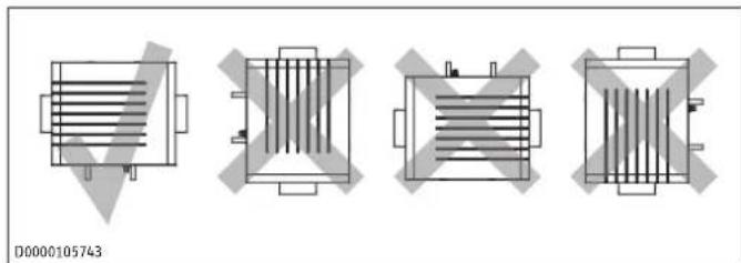
natural_image
Four technical diagrams of a heat exchanger or heat sink component, shown in different orientations with no visible text or symbols.When installing the appliance, you can select which side to have the air intake on.
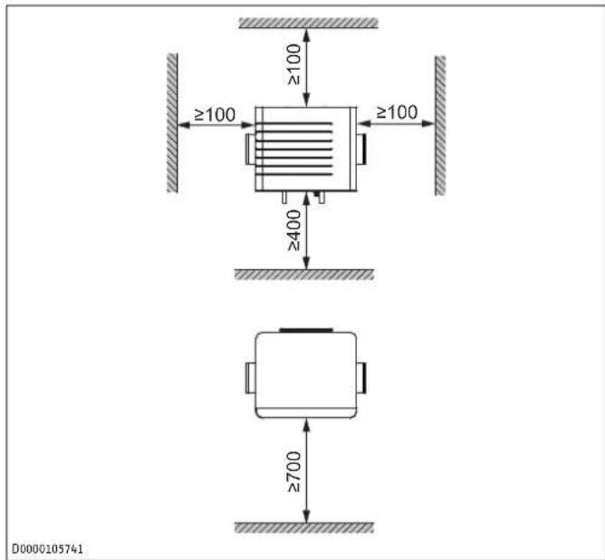
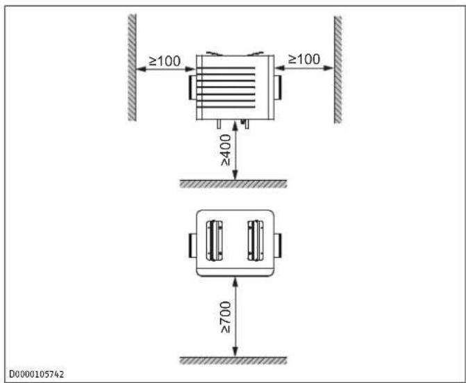
4.2.1 Minimum clearances
Distance from other components of the air duct mm 500 system (e.g. bends) and from the ventilation unit
Wall mounting
Ceiling mounting
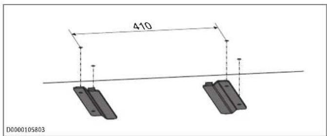
4.3 Profile rails
▶ Reach into the recesses on the sides of the appliance.
▶ Pull off the front cover.
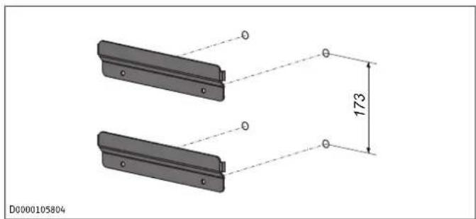
4.3.1 Fitting the profile rails to the wall or ceiling
To prevent slippage, the side ends of two of the profile rails are bent.
▶ Secure these profile rails below the ceiling or to the wall. Use suitable fixing materials in all drill holes. The precise positioning can be found in the dimensioned drawing for the appliance.
Ceiling mounting
Wall mounting
natural_image
Technical drawing of two mechanical components with dimension annotations (173 and 0), no readable text or symbols beyond measurement markers.If the clearance from the wall is greater at the top than at the bottom, slide the supplied washers between the lower profile rails to act as spacers.
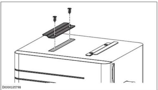
4.3.2 Fitting the profile rails to the appliance
Remove the film protecting the adhesive tape on the straight profile rails.
Ceiling mounting
natural_image
Technical line drawing of a mechanical assembly with clamps and a base plate (no text or symbols)▶ Affix the profile rails to the appliance at the pre-marked points.
▶ Screw the profile rails to the appliance using the supplied insulation material screws.
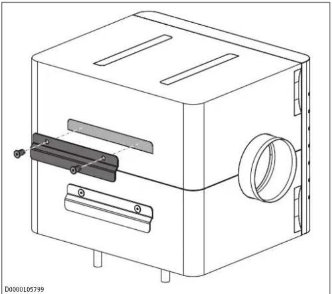
Wall mounting
natural_image
Technical line drawing of a mechanical device with mounting holes and internal components (no text or symbols)▶ Affix the profile rails to the appliance at the pre-marked points.
▶ Screw the profile rails to the appliance using the supplied insulation material screws.
4.4 Mounting the appliance
WARNING

Injury
If it is not properly secured, the appliance could fall off. A falling appliance could cause injury. This may damage the appliance. Damaged appliances may not function properly.
▶ Install the appliance so that it is not supported solely by the air duct.
▶ Use appropriate fixing materials.
▶ Follow these instructions when securing the profile rails.
NOTICE

Property damage
When the appliance is hooked in on one side, sudden dropping of the appliance on the side that has not yet been hooked in can cause damage to the mounting system, appliance or ceiling structure.
▶ Lift the appliance into position below the ceiling and slide the profile rails inside each other.
Once hooked in, the appliance can still be moved a few millimetres sideways. When properly installed, the bent ends of the profile rails prevent sideways slippage.
4.5 Connecting the condensate hose
NOTICE

Property damage
To ensure the condensate drains properly, never kink the condensate hose during installation. Lay the condensate hose with a minimum fall of 10 %. The appliance must be installed horizontally. The drain pipe may only contain one siphon. The condensate must be able to drain freely downstream of the siphon. The condensate must drain away via the domestic sewer system. The pipes must not rise in the domestic sewer system downstream of the siphon. The condensate drain must be free from the risk of frost.
NOTICE

Property damage
If there is no trap or unobstructed condensate drain installed, odours, corrosion and secondary air noise may occur. Condensate may leak out and cause damage.
▶ Install the condensate drain correctly, in accordance with these instructions.
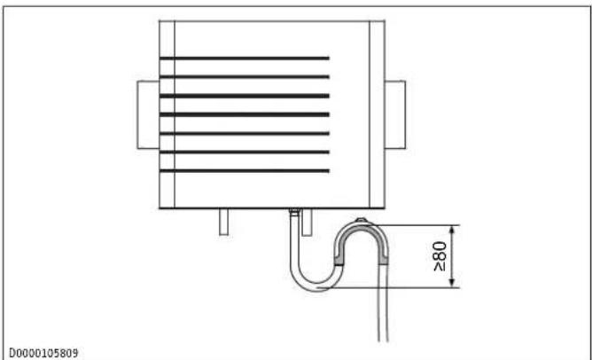
To ensure the unit is airtight, there may be no interruption in the condensate drain between the unit and the trap. Use the condensate hose and mounting bend supplied as standard delivery.
Connect the thinner end of the condensate hose to the appliance.
natural_image
Technical line drawing of a heat exchanger or cooling unit with a U-shaped pipe and internal flow lines (no text or symbols)▶ Use the mounting bend included in the standard delivery to install the condensate hose in such a way as to create a siphon with a water trap height of at least 80 mm.
Pour water into the siphon before you connect the condensate hose to the appliance.
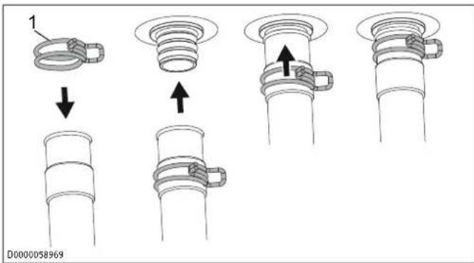
1 Hose clip
▶ Slide the hose clip onto the condensate hose far enough to be able to push the hose onto the condensate drain connector without squeezing the hose clip.
▶ Push the condensate hose onto the condensate drain connector.
▶ Push the hose clip towards the appliance so that it secures the hose on the condensate drain connector.
NOTICE: Dripping condensate can cause damage to the building or objects. Insulate the condensate drain connector.
4.6 Connecting air ducts
To install the appliance in the air duct, slide the supplied spiral duct push-fit connectors into the "air intake" and "air outlet" connections.
WARNING: Condensate can lead to mould and fungal growth in the air distribution system. Dripping condensate can cause damage to the building or objects. Insulate the air distribution system.
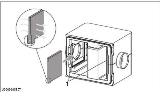
4.7 Filter
Never operate the unit without filters.
Available filter classes:
See chapter "Filter [▶ 16]".
The filter must be installed between the air intake and the heat exchanger.
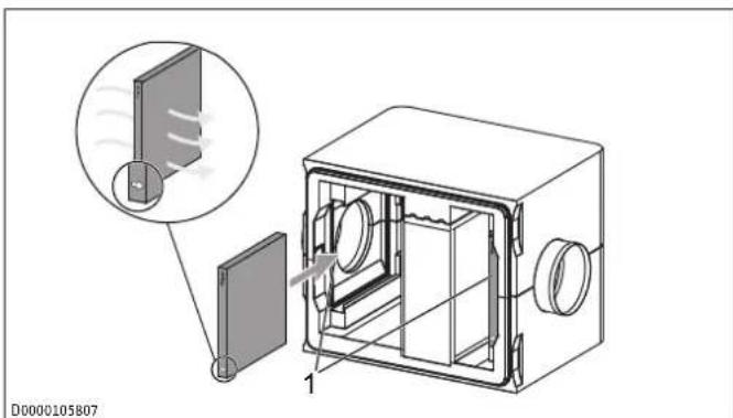
1 Possible filter positions
If the air flow is coming from the left, the arrow must point to the right. If the air flow is coming from the right, the arrow must point to the left.
▶ Check that the filter is in the correct position for the direction of flow.
If necessary, remove the filter from the appliance and install it on the other side of the appliance.
4.8 Connecting the heat source circuit
▶ Engineer the heat source circuit for the appliance according to the technical guides.
4.8.1 Laying pipes
To ensure you can ventilate the heat source circuit, lay the pipes with a rise towards the "Heat source flow" and "Heat source return" connections. A manual air vent valve is installed in the appliance.
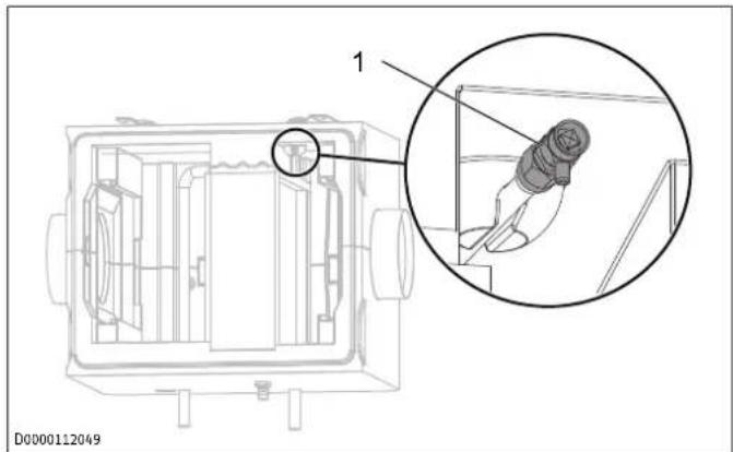
1 Manual air vent valve
4.8.2 Hydraulic connection
▶ Connect the appliance to the heat source circuit.
▶ Check for leaks.
To prevent damage from frost or condensation, ensure that the appliance's flow and return are insulated properly. Insulate the heat source circuit with diffusion-proof thermal insulation.
▶ As an option, you can install a dirt trap.
▶ Install optional shut-off valves for maintenance work.
4.8.3 Leak test
Once the appliance is connected to the heat source circuit, carry out a pressure test to check the appliance and system for leaks.
4.9 Filling the heat source circuit
Carry out a fill water analysis before filling the system. This analysis may, for example, be requested from the relevant water supply utility.
▶ To prevent damage to the appliance, observe the limits for the fill water. Soften or desalinate the fill water if required.
▶ Observe the requirements for the heat generator fill water.
▶ Observe local requirements (e.g. VDI 2035 in Germany).
▶ Check the fill water limits every time the system is topped up and during the annual system service.
▶ Do not add inhibitors or additives to the fill water.
▶ After filling the heating system, check the connections for leaks.
4.9.1 Venting the heat source circuit
▶ Vent the pipework carefully.
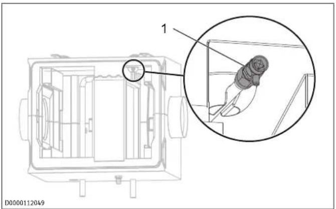
1 Manual air vent valve
▶ To vent, turn the cap of the manual air vent valve anticlockwise.
4.10 Completing the installation
▶ Position the front cover so that the horizontal grooves on the front face of the front cover are on the left.
▶ Push the front cover into the casing until the joints are free of gaps.
5 Cleaning
NOTICE: To prevent damage to components, never use abrasive or corrosive cleaning agents. Clean the casing with a damp cloth.
6 Cleaning (qualified contractors)
| Component Activity | Frequency | [months] |
| Heat exchanger Cleaning 6 | ||
| Condensate drain Cleaning 6 | ||
WARNING

Injury
If dirt or other objects are blocking the condensate drain, condensate may collect on the floor of the appliance housing. The appliance housing may be damaged as a result. Mildew and mould may form. This could then contaminate the air and be harmful to health.
▶ Check the condensate drain at regular intervals – at least once every six months.
NOTICE: The appliance will only function correctly if the condensate drain is working and is filled. Check the condensate drain at regular intervals - at least once every six months. Remove any dirt.
An evaporator cleaner is available from our product range for cleaning the heat exchanger.
▶ Pull off the front cover.
Flush the heat exchanger fins with a water hose. For best results, use an evaporator cleaning agent.
Cleaning the condensate drain
▶ To test the condensate drain, pour a litre of water onto the appliance base.
If the water does not drain safely and quickly, flush the condensate hose with low water pressure.
If the condensate hose is clogged, remove it from the appliance at the condensate connector and clean it thoroughly.
7 Maintenance
7.1 Filter

The higher the filter class, the higher the power consumption of the ventilation unit and the air flow rate drops.
Recommended filter class: ISO Coarse 65% We recommend that a higher filter class than that of the factory-installed filter should only be used during the pollen season. Filters with a higher filter class must be changed after 4 to 12 weeks of continuous operation, as the air permeability diminishes. For operation with filters of a higher filter class, the specification and testing has limited applicability.
In the delivered condition, the appliance does not have a filter installed. You can install a filter as an option.
You can obtain filters from us as accessories.
| Product name | Part number | Description | Filter class |
| Filterkassette G4 | 353742 | Coarse filter | ISO Coarse 65 % |
| FMK F7-1 FBF | 171474 | Fine filter | ISO ePM1 70 % |
| FMK M5-1 FBF | 171475 | Fine filter | ISO ePM10 50 % |
▶ Check the filter for the first time three months after commissioning the appliance.
▶ Check the filter regularly.
Maintenance intervals can differ greatly, e.g. depending on the season, due to high dust exposure or subject to the air flow rate.
▶ Reach into the recesses on the sides of the appliance.
▶ Pull off the front cover.
▶ Check to see how heavily contaminated the filter is.
If the filter is very dirty (solid layer of dust or distinct discolouration), replace the filter. If the filter is only lightly contaminated, you can continue to use it.
If the filter needs to be replaced, remove it carefully and dispose of it with household waste.
Replace filters at least once a year for hygiene reasons.
The filter must be installed between the air intake and the heat exchanger.
1 Possible filter positions
Insert the new filter. Pay attention to the direction of flow. The direction of flow is indicated by an arrow on the side of the filter. If the air flow is coming from the left, the arrow must point to the right. If the air flow is coming from the right, the arrow must point to the left.
▶ Check the filter for a correct, airtight fit.
7.2 Checking the condensate drain
NOTICE: Condensate escaping in an uncontrolled manner can damage the floor or items in the vicinity of the appliance. Once a month, check that the condensate drain is working correctly (visual inspection). When doing so, check for water collecting below or next to the appliance.
8 Troubleshooting
▶ If you cannot remedy the fault, contact your qualified contractor.
▶ To facilitate and speed up your enquiry, please provide the qualified contractor with the number from the type plate.
9 Specification
9.1 Dimensions and connections
Wall mounting
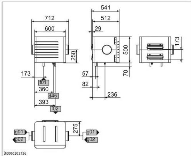
d45 Condensate drain Diameter mm 19
f01 Heat source flow Diameter mm 22
f02 Heat source return Diameter mm 22
g01 Air intake Diameter mm 180
g02 Air discharge Diameter mm 180
Ceiling mounting
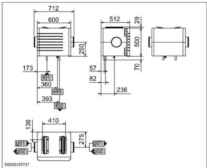
d45 Condensate drain Diameter mm 19
f01 Heat source flow Diameter mm 22
f02 Heat source return Diameter mm 22
g01 Air intake Diameter mm 180
g02 Air discharge Diameter mm 180
9.2 Pressure drop
Pressure drop in the air duct
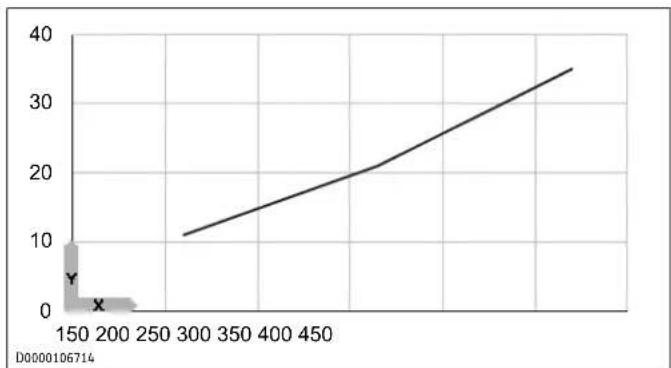
line
| X-Axis | Y-Axis | |---|---| | 300 | 11 | | 450 | 21 |X Air flow rate [m^3/h]
Y Pressure drop [Pa]
Pressure drop on the water side
| Water flow rate [m3/h] | Pressure drop [hPa] |
| 0.2 | 3.5 |
| 0.4 | 11.4 |
| 0.6 | 23.3 |
| 0.8 | 40.1 |
| 1.0 | 59.5 |
9.3 Data table
| LWF AR 1.5 | ||
| Product number 204818 | ||
| Heating outputs | ||
| Cooling capacity kW 1.55 | ||
| Heating output kW 3.4 | ||
| Versions | ||
| IP rating IP22 | ||
| Dimensions | ||
| Height mm 500 | ||
| Width mm 600 | ||
| Depth mm 512 | ||
| Weights | ||
| Weight kg 11 | ||
| Connections | ||
| Air connection diameter mm 180 | ||
| Condensate connection mm 19 | ||
| Values | ||
| Max. air flow rate m^3/h 420 | ||
| Min./max. application range °C -30 - 45 | ||
| Storage and transportation temperature | °C -10 - 70 | |
Example of heating output and cooling capacity
| Heating | Cooling | ||
| Water inlet temperature | °C | 55 7 | |
| Water flow rate | m^3/h | 0.99 | 0.885 |
| Water outlet temperature | °C | 52 8.5 | |
| Air inlet temperature | °C | 18 25 | |
| Air flow rate | m^3/h | 315 | 315 |
| Air outlet temperature | °C | 50 10 | |
| Output | kW | 3.4 | 1.55 |
10 Guarantee
The guarantee conditions of our German companies do not apply to appliances acquired outside of Germany. In countries where our subsidiaries sell our products a guarantee can only be issued by those subsidiaries. Such guarantee is only granted if the subsidiary has issued its own terms of guarantee. No other guarantee will be granted.
We shall not provide any guarantee for appliances acquired in countries where we have no subsidiary to sell our products. This will not affect warranties issued by any importers.
11 Environment and recycling
▶ Dispose of the appliances and materials after use in accordance with national regulations.
If a crossed-out waste bin is pictured on the appliance, take the appliance to your local waste and recycling centre or nearest retail take-back point for reuse and recycling.
This document is made of recyclable paper.
▶ Dispose of the document at the end of the appliance's life cycle in accordance with national regulations.
natural_image
Four technical diagrams of a heat exchanger or heat sink component, shown from different angles and orientations (no text or symbols present)natural_image
Technical line drawing of a mechanical assembly with mounting brackets and a base plate (no text or symbols)natural_image
Technical line drawing of a mechanical device with mounting holes and internal components (no text or symbols)natural_image
Technical line drawing of a heat exchanger or cooling unit with a U-shaped pipe and 280mm dimension标注 (no text or symbols on the diagram itself)natural_image
Four schematic diagrams of electronic component layouts with no visible text or symbolsnatural_image
Technical drawing of two mechanical components with dimension annotations (173 and 0) and no readable text or symbols.natural_image
Technical line drawing of a mechanical assembly with two plates and mounting holes (no text or symbols)natural_image
Technical line drawing of a mechanical device with mounting holes and internal components (no text or symbols)natural_image
Technical line drawing of a mechanical component with a U-shaped pipe and internal parallel lines (no text or symbols)natural_image
Four technical diagrams of heat exchanger or heat exchanger components with no visible text or symbolsnatural_image
Technical drawing of two mechanical components with dimension annotations (173 and a small circle), no readable text or symbols beyond measurement markers.natural_image
Technical line drawing of a mechanical assembly with two plates and mounting holes (no text or symbols)natural_image
Technical line drawing of a mechanical device with mounting holes and internal components (no text or symbols)natural_image
Technical line drawing of a heat exchanger or cooling unit with a U-shaped pipe and height dimension labeled '≥80' (no text or symbols beyond the label)natural_image
Four technical diagrams of a heat exchanger or heat sink component, shown in different orientations with no visible text or symbols.natural_image
Technical line drawing of a mechanical assembly with two plates and mounting holes (no text or symbols)natural_image
Technical line drawing of a mechanical device with mounting holes and internal components (no text or symbols)natural_image
Technical line drawing of a heat exchanger or cooling unit with a U-shaped pipe and 280mm dimension标注 (no text or symbols on the diagram itself)natural_image
Technical diagram of a microwave oven with labeled components and airflow indicators (no text or symbols)D0000105807
natural_image
Four technical diagrams of a heat exchanger or heat sink component, shown from top to bottom views with no visible text or symbols.natural_image
Technical line drawing of a mechanical assembly with clamps and a base plate (no text or symbols)natural_image
Technical line drawing of a mechanical device with mounting holes and internal components (no text or symbols)natural_image
Technical line drawing of a heat exchanger or cooling unit with a U-shaped pipe and horizontal heat exchangers (no text or symbols)natural_image
Four schematic diagrams of heat exchanger or heat exchanger components with no text or symbolsnatural_image
Technical line drawing of a mechanical assembly with mounting brackets and a base plate (no text or symbols)natural_image
Technical line drawing of a mechanical device with mounting holes and internal components (no text or symbols)natural_image
Technical line drawing of a heat exchanger or cooling unit with a U-shaped pipe and internal heat flow lines (no text or symbols)D0000105809
natural_image
Four schematic diagrams of electronic component layouts with no visible text or symbolsnatural_image
Technical line drawing of a mechanical assembly with two plates and mounting holes (no text or symbols)natural_image
Technical line drawing of a mechanical device with internal components and mounting holes (no text or symbols)natural_image
Technical line drawing of a heat exchanger or cooling unit with a U-shaped pipe and height dimension labeled '≥80' (no text or symbols beyond the dimension)D0000105809