FX-EGH2800T - Mechanical chipper Fuxtec - Free user manual and instructions
Find the device manual for free FX-EGH2800T Fuxtec in PDF.

| Product type | Electric garden shredder |
| Brand | Fuxtec |
| Model | FX-EGH2800T |
| Power supply | 230-240 V~, 2800 W, 50 Hz |
| Rotation speed | 60 rpm |
| Max. branch diameter | 44 mm |
| Collection bag capacity | 60 L |
| Cutting system | Roller with 1 knife |
| Dimensions (L x W x H) | 48 x 42 x 91 cm |
| Net weight | 16.8 kg |
| Sound power level (guaranteed) | 92 dB(A) |
| Protection rating | IPX4 |
| Motor type | Electric |
| Material feed | Automatic |
| Recommended use | Branches, green waste |
| Transport handle | Yes |
| Wheel diameter | 18 cm |
| Safety | Safety switch, overload protection |
| Maintenance | Cleaning after use, adjusting the counterplate |
| Spare parts | Counterplate, blades, collection bag |
| Warranty | According to conditions, contact customer service |
| Manufacturer | Fuxtec GmbH, Germany |
Frequently Asked Questions - FX-EGH2800T Fuxtec
User questions about FX-EGH2800T Fuxtec
0 question about this device. Answer the ones you know or ask your own.
Ask a new question about this device
Download the instructions for your Mechanical chipper in PDF format for free! Find your manual FX-EGH2800T - Fuxtec and take your electronic device back in hand. On this page are published all the documents necessary for the use of your device. FX-EGH2800T by Fuxtec.
USER MANUAL FX-EGH2800T Fuxtec
natural_image
Line drawing of a manual pump or scrubber device with wheels and handle (no text or symbols)
natural_image
Orange icon of a person reading a book on black background (no text or symbols)
Deutsch....8
English Version....21
- Introduction and safety....21
- Note on safe use 22
- Symbols on the Product and in the Instructions....24
- Product overview 25
- Assembly instructions....26
- Operation....27
- Cleaning and maintenance .... 30
- Troubleshooting....31
- Maintenance....31
- accessories and spare parts....32
- General description....32
- Technical data....32
- Warranty....32
-
Disposal....33
-
Customer Service .... 33
- Copyright 33
natural_image
Person adjusting a tire with a hand, showing mechanical components and a labeled arrow (H), no readable text or symbols present.
natural_image
Two views of a car wheel assembly: top view shows a mounted vehicle with wheels, bottom view shows a close-up of the component being adjusted (no text or symbols visible)Abb. 1A
Abb. 2

natural_image
Close-up of a robotic device with white protective cover and labeled component A, shown from side to front (no text or symbols on the device itself)ACHTUNG:
natural_image
Technical diagram of a mechanical assembly with labeled component A (no text or symbols beyond label)Achtung
natural_image
Close-up of a mechanical component with labeled parts A and B, showing internal structure and mounting holes (no text or symbols beyond labels)(Abb. 6A)

natural_image
Close-up of a mechanical component with a labeled component 'B' and arrow indicator (no readable text or symbols beyond label)Abb. 6B)
17. INTRODUCTION AND SAFETY
General information
Read this original instruction manual carefully before using the product for the first time and follow all instructions. Keep the document in a safe place for future reference or for subsequent owners.
Familiarize yourself with the functions and proper use of the product. Observe all safety instructions listed in the service manual. Always act responsibly and considerably toward third parties. The operator is responsible for accidents or hazards caused to third parties.
Intended use
The product may only be used for its intended purpose. Any other use is considered improper. The user or operator is solely liable for any resulting damage or injury of any kind; the manufacturer accepts no responsibility for this. Please note that the product is not designed for commercial, trade, or industrial use. Any warranty or liability is excluded if the product is used in such areas of application or for comparable activities.
Do not allow anyone who has not read and understood these instructions completely to assemble, start up, adjust, or operate the product. This product is intended exclusively for well-insulated rooms or for temporary use.
Safety instructions
Read all safety instructions, operating instructions, illustrations, and technical information supplied with the product. Failure to follow these instructions may result in serious injury or damage. The operator is responsible for using the product as intended, paying attention to the environment, and taking special care of other people, especially children. Always follow the specified safety guidelines.
18. NOTE ON SAFE USE
WARNING!
Read all safety instructions and directions. Failure to do so may result in electric shock, fire, or serious injury.
KEEP ALL WARNING NOTICES AND INSTRUCTIONS FOR FUTURE REFERENCE.
Safe working practices
General warning!
This appliance is not intended for use by persons (including children) with reduced physical, sensory, or mental capabilities, or lack of experience and knowledge, unless they are supervised or instructed by a person responsible for their safety.
Children must not play with the device and must be supervised.
Instruction
Read the operating instructions before use and familiarize yourself with the device.
Preparation
Do not allow children to operate the device.
Do not work near uninvolved persons.
Always wear ear protection and safety goggles.
Do not wear loose clothing or clothing with cords.
Only work in open areas and on firm, level ground.
Do not use on asphalt or gravel where ejected material could cause injury.
Before starting up, check all screws, nuts, bolts, and protective devices; replace damaged or illegible labels.
Maintenance and storage
Before maintenance, inspection, accessory replacement, or storage, disconnect the power supply, disconnect the device from the mains, bring moving parts to a standstill, and remove keys if necessary.
Allow the device to cool down.
Always allow the device to cool down before storing it.
Workplace safety
Keep the workplace clean and well lit.
Do not use in potentially explosive environments or near flammable liquids, gases, or dust.
Keep children and other persons away.
Safety instructions for electrical appliances
The power plug must fit the outlet; do not modify or use adapters.
Avoid physical contact with earthed surfaces.
Protect from moisture and rain.
Do not misuse the cable (e.g., for carrying, pulling, or hanging).
Damaged cables must only be replaced by qualified personnel.
Only use suitable extension cables outdoors.
In damp environments, use only with a residual current device (30 mA).
Lay the cable so that it cannot become trapped.
Personal safety
Work with concentration and caution. Do not use the device when tired or under the influence of drugs, alcohol, or medication.
Wear personal protective equipment, especially safety goggles.
Only connect the device to the mains when it is switched on and transport it when the switch is off.
Remove adjustment tools before starting operation.
Ensure that the device is stable.
Wear close-fitting clothing; keep jewelry and long hair away.
Connect the dust extraction system (if available) correctly.
Careful handling of electrical equipment
Do not overload the device; use the machine suitable for the work in question.
Have defective switches repaired.
Disconnect the power plug before making adjustments, changing accessories, or shutting down the machine.
Keep devices out of the reach of children.
Maintain the device regularly and have damaged parts repaired.
Keep cutting tools sharp and clean.
Only use the device and accessories for their intended purpose.
Service
Only have the device serviced by qualified personnel using original replacement parts.
Before maintenance, disconnect the power plug, bring moving parts to a standstill, and allow the device to cool down.
Only perform the maintenance work described here yourself.
Check screws regularly.
Do not make any unauthorized modifications or use unauthorized parts.
Only use original replacement parts.
Always store the device in a dry place.
Never transport the device with the engine running. Protect the device from damage during transport.
Approved accessories
Only use accessories that are specifically approved for your model and supplied with it.
Other accessories must not be used – they increase the risk of accidents.
We accept no liability for damage or injury caused by unauthorized accessories.
19. SYMBOLS ON THE PRODUCT AND IN THE INSTRUCTIONS
This manual and the product itself use symbols to indicate potential hazards. These safety symbols and their explanations must be fully understood. Please note: The warning notices alone do not eliminate hazards and do not replace the necessary safety measures for accident prevention.

Read this operating manual carefully before using the product and keep it in a safe place for future reference.

Safety goggles and hearing protection (e.g., soundproof helmet) must be worn during operation. In case of danger of falling objects, use a protective helmet as well.

Wear gloves to protect your hands.

Keep other people away.

Do not expose to rain.

Warning! Danger.
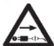
Caution! Flying parts
Always switch off the machine, pull out the plug and wait until the cutting disc has come to a complete standstill.

Keep hands and feet away from openings during operation.

Caution: rotating blades.

Wait until all moving parts have come to a complete standstill before touching them.

Do not step on the collection container.

Guaranteed sound power level LwA = 92 dB(A)

CE mark
The product complies with the requirements and regulations of the European Community.
20. PRODUCT OVERVIEW
Please check that the item is complete according to the description. If any parts are defective, please contact our FUXTEC customer service.
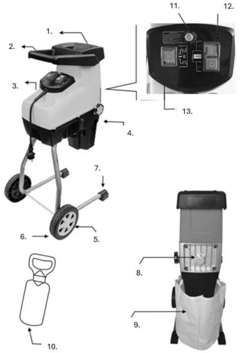
Parts overview
- Filling funnel
- Hand
- Type F plug
- Counterplate adjustment knob
- Wheel cover
- Wheel
- Support foot
- Back cover
- Catch pocket
- Plug
- Safety switch
- On/off switch
- Forward/reverse switch
21. ASSEMBLY INSTRUCTIONS
Assembling the shredder
- Place the supplied washer (B) and sleeve (C) on the wheel axle. (Fig. 1B)
- Mount the wheels (D) and tighten the nut (E) by hand. (Fig. 1C)
- Use the supplied Allen key (F) to secure the wheel axle and tighten the nut with the wrench (G) at the same time. (Fig. 1D)
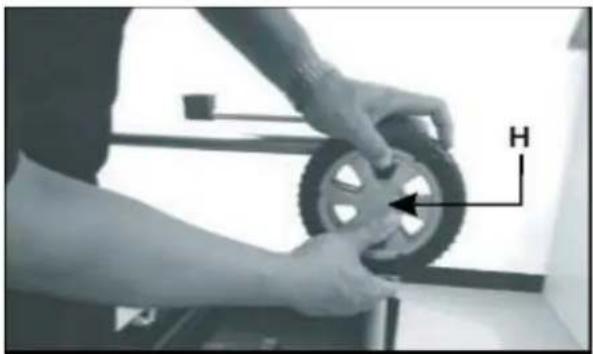
- Finally, place the wheel cover (H) in the center of the wheel. (Fig. 1E)
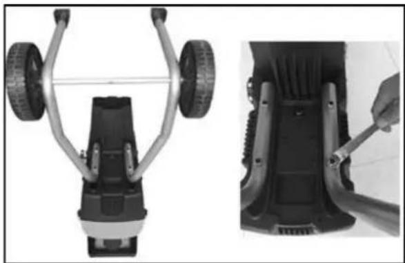
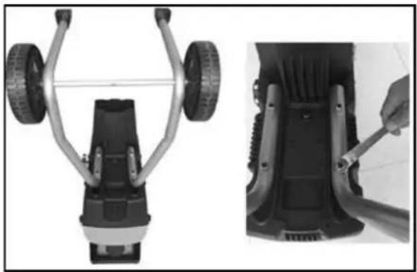
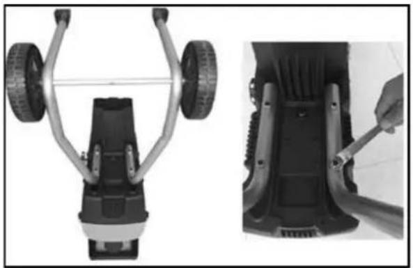
- Turn the shredder over and place the support tube on top. (Fig. 1A)
- Tighten the 4 screws with a wrench to secure the tube to the housing. (Fig. 1A)
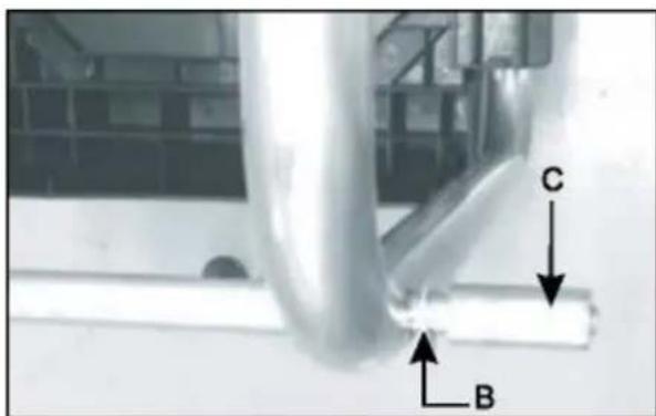
Fig. 1B
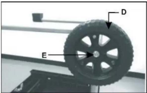
Fig. 1C
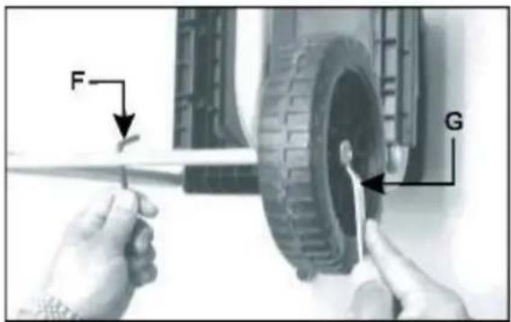
Fig. 1D
natural_image
Person adjusting a tire with a hand, showing mechanical components and a labeled arrow (H), no readable text or symbols present.Fig. 1E
natural_image
Two views of a mechanical device with wheels and a close-up view showing a tool interacting with the base (no text or symbols visible)Fig. 1A

natural_image
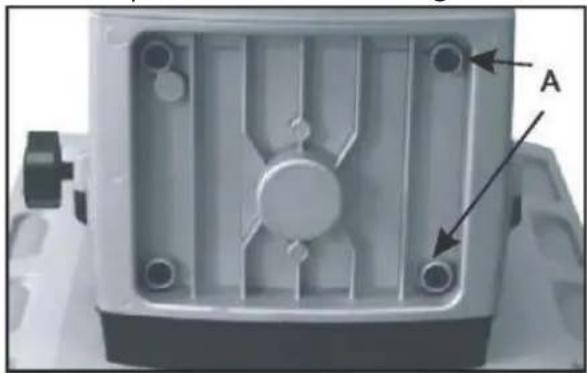
Close-up of a robotic arm with white protective cover and labeled component A, shown in two views (no text or symbols on the robot itself)Fig. 2
CAUTION:
Be careful when tilting the device onto its wheels, as it has an uneven weight distribution when tilted and transported on its wheels.
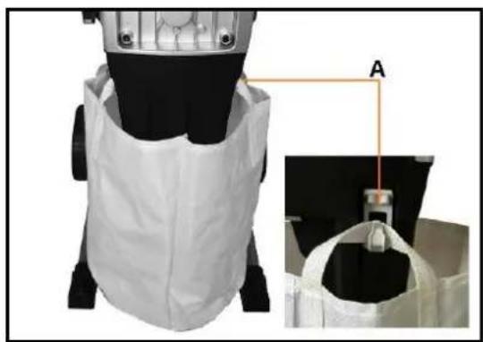
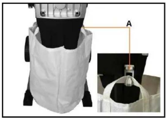
Mounting the catch bag
- Hook the suspension hooks onto the two hooks (A) on both sides of the lower housing. (Fig. 2)
22. OPERATION
Preparation
- Before starting the machine, look into the feed hopper and make sure it is empty.
- Always ensure that you are standing securely and have a firm footing. Do not overreach. Never stand higher than the machine base when filling it with material.
- Always keep away from the ejection area during operation.
- When filling, take particular care to ensure that no metal, stones, bottles, cans, or other foreign objects are present.
- If the cutting mechanism encounters a foreign object or if unusual noises or vibrations occur ( ), switch off the machine immediately, allow it to come to a complete stop, disconnect the power plug (for electric models) and proceed as follows:
a) Check the machine for damage.
b) Check and tighten any loose parts.
c) Have damaged parts repaired or replaced only with replacement parts of the same specifications.
6. Do not allow shredded material to accumulate in the discharge area, as this may prevent proper emptying and cause material to be thrown back through the feed opening.
7. All protective devices and deflectors must be installed and in perfect condition.
8. Never transport the machine while the engine is running.
9. Switch off the machine and disconnect the power plug (for electric models) as soon as you leave the work area.
10. Do not tilt the machine while the engine is running.
11. Keep the engine free of dirt and debris.
Starting and stopping
- Set the forward/reverse switch (A) to the forward position ("+"")
- Press the on/off switch (B) to ON (I) to start the motor.
- Press the ON/OFF switch (B) to OFF (O) to stop the engine.
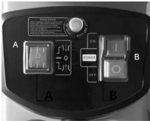
(Fig. 3)
Caution
Damage to the device due to improper operation.
Incorrect handling can result in damage to the device.
→ Only feed material after the device has been switched on. Do not feed material after the device has been switched off.
Note
The device is equipped with a safety switch that prevents it from accidentally restarting after a power failure
Overload protection
This device has an overload protection system.
To protect the motor, the power supply is automatically switched off when the motor is overloaded.
Wait at least 1 minute before restarting the device:
- Press the reset button.
- Press the on/off switch.
If the motor does not start, proceed as follows:
- Press the safety switch (A).
- Set the forward/reverse switch (B) to the reverse position.
- Hold the on/off switch (ON [I]) to remove any objects blocking the blades.
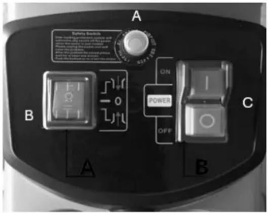
(Fig. 4)
Caution:
Always wear protective gloves when performing these steps!
Notes on use
- Place the material to be shredded into the opening on the right-hand side. It will be pulled in automatically by the counterclockwise rotating blade.
- Do not fill the opening completely to prevent blockages.
- Alternate between adding branches and slightly damp, rotted material – this also prevents blockages.
- Compost soft kitchen waste – do not put it through the shredder!
- Branches with leaves must be completely shredded and removed before adding new material. Ensure that the shredded material falls freely into the collection box.
- The ventilation opening must not be blocked by shredded material.
- Continuous shredding of thick wood or branches can block the device.
- Soft material such as leaves or twigs can easily clog the feed chute – push them in with the pusher.
- Check the material for nails and stones before shredding, as these can damage the shredder severely or irreparably.
Adjusting the counter plate
To achieve optimum shredding results and prevent damage to the blade, the counter plate must be adjusted regularly. Adjustment is also necessary if so-called interlocking occurs.
- Turn the counter plate adjustment knob (A) clockwise until you hear a slight rubbing noise
and fine aluminum chips fall out of the discharge channel for a short time. (Fig. 5A and 5B)
- The chopped material should then be cut completely again.
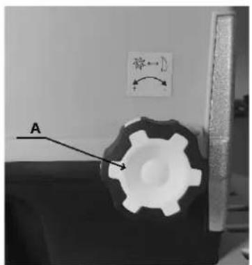
(Fig. 5A)
(Fig. 5B)
natural_image
Technical diagram of a mechanical assembly with labeled component A (no text or symbols beyond label)Caution
- Remove dirt and material residues after each use.
- Do not clean the device with running water or high pressure.
- Do not use cleaning agents or solvents.
- Use a soft brush or cloth for cleaning.
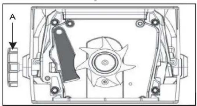
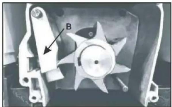
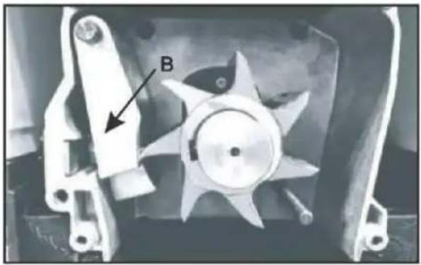
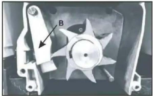
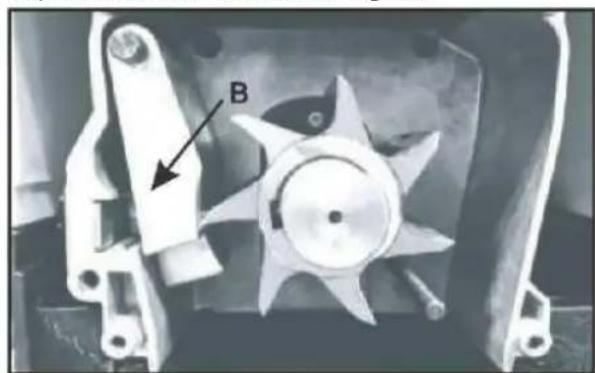
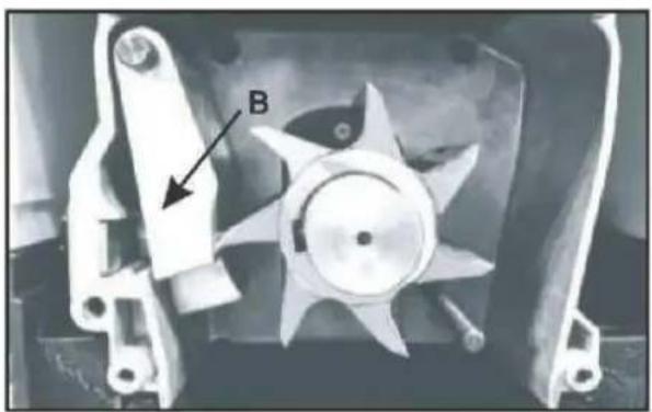
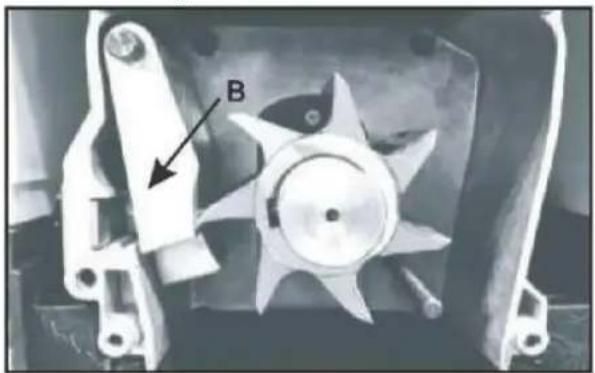
Replacing the counter plate
- Open the rear cover by loosening the 4 screws (A). (Fig. 6A)
- Remove the counter plate (B) and insert a new one. (Fig. 6B)
- Replace the rear cover and tighten the screws with a wrench.
natural_image
Close-up of a mechanical component with labeled points A and an arrow pointing to a circular feature (no text or symbols beyond labels)(Fig. 6A)
Fig. 6B)
natural_image
Mechanical component with labeled part B, showing fan and blades (no readable text or symbols)23. CLEANING AND MAINTENANCE
Before starting any cleaning or maintenance work, make sure that the garden shredder is switched off and disconnected from the power supply. Always wear sturdy leather gloves when cleaning the cutting blades.
To ensure optimum performance of the garden shredder, it must be kept clean.
- Always clean the garden shredder immediately after use.
- Do not allow any material to dry or harden on the surfaces of the garden shredder. This will directly impair the shredding performance.
- Ensure that the feed chute and discharge channel are always clean and free of residue.
- Regularly check that all nuts, bolts, and screws are tight.
- Always have damaged or worn parts repaired or replaced by qualified personnel.
- Do not use cleaning agents or solvents, as these can cause irreparable damage to the device. Chemicals can attack plastic parts.
Caution:
Have your garden shredder checked and serviced by qualified personnel. Do not attempt to repair the device yourself if you are not trained to do so.
Warning
Never use a high-pressure cleaner or running water to clean the shredder! Remove dirt and plant debris from the spiral blade with a brush.
Wipe the outside of the shredder with a cloth dampened with mild detergent and water.
24. TROUBLESHOOTING
| Cause | Action |
| Safety switch | Check that the switch is working properly. |
| Power failure | Check the power cable, plug, and house fuse. |
| Material blocked in the feed hopper | Switch off the shredder. Carefully pull the material out of the feed chute. Switch the shredder back on and feed thick branches in such a way that the blade does not immediately start cutting at the pre-notched points. |
| The material to be shredded is too soft | Feed in wood or shred dried branches. |
| The device does not start | Press the reset button and then press the on/off switch. If it still does not start, follow the steps in the "Overload protection" section on page 6. |
25. MAINTENANCE
Only use original accessories and original replacement parts.
Only a regularly maintained and treated device can provide satisfactory assistance.
Inadequate maintenance and care can lead to unforeseen accidents and injuries.
26. ACCESSORIES AND SPARE PARTS
Use only original accessories and spare parts to ensure the safety and proper functioning of the device. For more information, visit www.FUXTEC.com.
27. GENERAL DESCRIPTION
Item number: FX-EGH2800T
Item description: FUXTEC Electric Garden Shredder FX-EGH2800T
28. TECHNICAL DATA
| Type | Specification |
| Motor | Electric |
| Drive type | Electric |
| Fuel | Electric |
| Nominal voltage | 230–240 V |
| Nominal speed | 60 rpm |
| Power | 2800 W (P40) |
| Sound power level (measured) | 89.9 dB(A), K=2.45 dB |
| Sound power level (guaranteed) | 92 dB(A) |
| Sound pressure level | 70.3 dB(A), K=3 dB |
| Cable length | VDE + 0.13 m |
| Max. branch thickness | 44 mm |
| Cutting system | Roller |
| Type of collection container | Bag |
| Capacity of the collection container | 60 L |
| Funnel size | 2.9 × 12 cm, max. 4.4 cm |
| Material feed | Automatic |
| Suitable | Branches |
| Number of blades | 1 |
| Wheel diameter | 18 cm |
| Transport handle | Yes |
| Dimensions (L × W × H) | 48 × 42 × 91 cm |
| Protection class (IP) | IPX4 |
| Net | 16.8 kg |
| Delivered pre-assembled | No |
29. WARRANTY
The warranty period begins on the date of purchase. Please keep the proof of purchase in a safe place. The warranty does not cover wear parts and does not apply to damage caused by improper use, improper handling, the use of force, technical modifications, the use of unauthorized accessories or
spare parts, or repair attempts by unauthorized persons. Warranty work may only be carried out by authorized specialist companies or service partners. These conditions apply in addition to the statutory warranty rights, which may vary from country to country.
30. DISPOSAL
The packaging material consists mainly of recyclable materials. Please dispose of all packaging components in accordance with local waste separation regulations. By recycling the packaging, you are making a valuable contribution to environmental protection and the sustainable use of resources.
This product must not be disposed of with normal household waste. In accordance with European Directive 2012/19/EU on waste electrical and electronic equipment (WEEE), the device must be taken to an approved collection point for waste electrical and electronic equipment at the end of its service life.
Proper disposal and recycling of the materials help protect the environment and human health. For more information on return and disposal, please contact your local waste authority or the retailer where you purchased the product.
31. CUSTOMER SERVICE
If you have any questions about warranty, repairs, or replacement parts, please contact:
FUXTEC GmbH
Kappstraße 69
71083 Herrenberg
Germany
Phone:
Email: info@fuxtec.de
Note: Please do not send any returns or repairs to this address. For returns under warranty, please contact our customer service.
32. COPYRIGHT
All rights reserved. The contents of this manual are protected by copyright. Their use is permitted within the scope of operation. Any use or reproduction beyond this is not permitted without the written consent of FUXTEC GmbH. FUXTEC GmbH reserves the right to make changes to this operating manual without prior notice.
VERSION FRANÇAISE
33. INTRODUCTION ET SÉCURITÉ
Remarques générales
Attention! Projections
Attention : lames rotatives.

natural_image
Person adjusting a tire with a hand, showing mechanical components and a labeled arrow (H), no readable text or symbols present.Fig. 1E
natural_image
Two views of a car wheel assembly: top view shows front wheel and lower side view with a hand using a tool (no text or symbols visible)Fig. 1A

natural_image
Close-up of a robotic device with white protective cover and labeled component A, shown from close-up (no text or symbols on the device itself)Fig. 2
ATTENTION :
natural_image
Technical diagram of a mechanical assembly with labeled component A (no text or symbols beyond label)Attention
natural_image
Close-up of a mechanical component with labeled parts A and B, showing internal structure and mounting holes (no text or symbols beyond labels)(Fig. 6A)
Fig. 6B)
natural_image
Close-up of a mechanical component with a labeled component 'B' and arrow indicator (no readable text or symbols beyond label)39. NETTOYAGE ET ENTRETIEN
natural_image
Person adjusting a tire with a hand, showing mechanical components and a labeled arrow (H), no readable text or symbols present.Fig. 1E

natural_image
Two views of a car wheel assembly: top view shows a mounted vehicle with wheels, bottom view shows a close-up of the component being adjusted (no text or symbols visible)Fig. 1A

natural_image
Close-up of a robotic arm with white protective cover and labeled component A, shown in two views (no text or symbols on the robot itself)Fig. 2
ATTENZIONE:
(Fig. 4)
Attenzione:
natural_image
Technical diagram of a mechanical assembly with labeled component A (no text or symbols beyond label)Attenzione
natural_image
Close-up of a mechanical component with labeled parts A and an arrow pointing to a circular feature (no text or symbols beyond labels)(Fig. 6A)
Fig. 6B)
natural_image
Mechanical component with labeled part B, showing fan and blades (no readable text or symbols)58. ACCESSORI E RICAMBI
natural_image
Person adjusting a tire with a hand, showing mechanical components and a labeled arrow (no text or symbols on the object itself)Fig. 1E
natural_image
Two views of a vehicle chassis showing front and side views with visible wheels and brackets (no text or symbols)Fig. 1A

natural_image
Close-up of a robotic arm with white protective cover and labeled component A, shown from side to front (no text or symbols on the main subject)Fig. 2
ATENCIÓN:
natural_image
Technical diagram of a mechanical assembly with labeled component A (no text or symbols beyond label)Atención
natural_image
Close-up of a mechanical component with labeled parts A and B, showing internal structure and mounting holes (no text or symbols beyond labels)(Fig. 6A)
Fig. 6B)

natural_image
Close-up of a mechanical component with a labeled component 'B' and arrow indicator (no readable text or symbols beyond label)71. LIMPIEZA Y MANTENIMIENTO
natural_image
Person adjusting a tire with a hand, showing a mechanical component (no text or symbols visible)Fig. 1E

natural_image
Two views of a car wheel assembly: top view shows front wheel and lower side view with a hand using a tool (no text or symbols visible)Fig. 1A

natural_image
Close-up of a robotic device with white protective cover and labeled component A, shown from close-up (no text or symbols on the device itself)Fig. 2
CUIDADO:
natural_image
Technical diagram of a mechanical assembly with labeled component A (no text or symbols beyond label)Atenção
natural_image
Close-up of a mechanical component with labeled points A and an arrow pointing to a circular feature (no text or symbols beyond labels)(Fig. 6A)
Fig. 6B)
natural_image
Mechanical component with labeled part B, showing fan and blades (no readable text or symbols)natural_image
Person adjusting a tire with a hand, showing mechanical components and a labeled arrow (H), no readable text or symbols present.Fig. 1E

natural_image
Two views of a car wheel assembly: top view shows front wheel and lower side view with a hand using a wrench (no text or symbols visible)Afb. 1A
natural_image
Close-up of a robotic device with white protective cover and labeled component A, shown from close-up (no text or symbols on the device itself)Fig. 2
LET OP:
natural_image
Technical diagram of a mechanical assembly with labeled component A (no text or symbols beyond label)Let op
natural_image
Close-up of a mechanical component with labeled points A and an arrow pointing to a circular feature (no text or symbols beyond labels)(Afb. 6A)
Fig. 6B)
natural_image
Close-up of a mechanical component with a labeled part 'B' and arrow indicator (no readable text or symbols beyond label)103. REINIGING EN ONDERHOUD
natural_image
Person adjusting a tire with a hand, showing mechanical components and a labeled arrow (H), no readable text or symbols present.Fig. 1E

natural_image
Two views of a car wheel assembly: top view shows a mechanical component with wheels, bottom view shows a hand using a tool to adjust the part (no text or symbols visible)Bild 1A

natural_image
Close-up of a robotic arm with white fabric and a magnified inset showing a bag attachment (no text or symbols visible)Fig. 2
FÖRSIKTIGHET:
natural_image
Technical line drawing of a mechanical assembly with no visible text or symbolsFörsiktighet
natural_image
Close-up of a mechanical component with labeled points A and an arrow pointing to a circular feature (no text or symbols beyond labels)(Fig. 6A)
Fig. 6B)
natural_image
Mechanical component with a star-shaped fan and labeled component B (no text or symbols beyond label)119. RENGÖRING OCH UNDERHÅLL
natural_image
Person adjusting a tire with a hand, showing mechanical components and a labeled arrow (H), no readable text or symbols present.Rys. 1E

natural_image
Two views of a car wheel assembly: top view shows a mechanical component with wheels, bottom view shows a hand using a tool to adjust the part (no text or symbols visible)Rys. 1A
natural_image
Close-up of a robotic arm with white fabric and a magnified inset showing a bag attachment (no text or symbols visible)Rys. 2
UWAGA:
natural_image
Technical diagram of a mechanical assembly with labeled component A (no text or symbols beyond label)Uwaga
natural_image
Close-up of a mechanical component with labeled points A and an arrow pointing to a circular feature (no text or symbols beyond labels)(Rys. 6A)
(Rys. 6B)

natural_image
Mechanical component with a star-shaped fan and labeled component B (no readable text or symbols)135. CZYSZCZENIE I KONSERWACJA
www.fuxtec.com | info@fuxtec.com

www.FUXTEC.com