CW-6000 - Boiler Vevor - Free user manual and instructions
Find the device manual for free CW-6000 Vevor in PDF.

| Product type | Industrial water chiller |
| Brand | Vevor |
| Model | CW-6000 |
| Power supply | AC220-240V / AC120V, 50/60 Hz |
| Power | 1500 W |
| Cooling capacity | 3.2 kW (50 Hz) / 3.5 kW (60 Hz) |
| Refrigerant | R410a |
| Noise level | ≤ 8.0 dB (according to manual) |
| Water tank capacity | 15 L |
| Max pump flow rate | 65 L/min |
| Pump power | 370 W (220V) / 600 W (120V) |
| Main material | Iron and copper |
| Safety | Compressor overcurrent protection, flow alarm, overheat alarm |
| Adjustable temperature range | -20°C to 40°C (smart mode) |
| Control modes | Smart and constant temperature |
| Air filter | Regular cleaning required |
| Installation | Connect inlet/outlet hoses, fill water tank |
| Usage | Professional use only |
| Support | www.vevor.com/support |
Frequently Asked Questions - CW-6000 Vevor
User questions about CW-6000 Vevor
0 question about this device. Answer the ones you know or ask your own.
Ask a new question about this device
Download the instructions for your Boiler in PDF format for free! Find your manual CW-6000 - Vevor and take your electronic device back in hand. On this page are published all the documents necessary for the use of your device. CW-6000 by Vevor.
USER MANUAL CW-6000 Vevor
Technical Support and E-Warranty Certificate www.vevor.com/support
INDUSTRIAL WATER CHILLER USER MANUAL
MODEL: CW-6000
We continue to be committed to provide you tools with competitive price. "Save Half", "Half Price" or any other similar expressions used by us only represent estimate of savings you might benefit from buying certain tools with us compared top brands and does not necessarily mean to cover all categories of tools offered are kindly reminded to verify carefully when you are placing an order with us actually saving half in comparison with the top major brands.
MODEL: CW-6000

NEED HELP? CONTACT US!
Have product questions? Need technical support? Please feel fr contact us:
Technical Support and E-Warranty Certificate www.vevor.com/support
This is the original instruction, please read all manual instruction carefully before operating. VEVOR reserves a clear interpretation user manual. The appearance of the product shall be subject to product you received. Please forgive us that we won't inform you there are any technology or software updates on our product.

Warning-To reduce the risk of injury, user must read in manual carefully.
WARN
- PLEASE MAKE SURE THAT THE POWER SUPPLY AND THE POWER OUTLET ARE IN GOOD CONTACT AND THE GROUNDING WIRE MUST BE FIRM!
Although the average working current of the chiller is small, the instantaneous working current can sometimes reach 6\~10 amperes (the instantaneous working current of the AC110V power supply model is possible up to 10\~15 amperes
- PLEASE MAKE SURE THAT THE WORKING CHILLER HAS A STABLE AND NORMAL VOLTAGE!
Since the refrigeration compressor is more sensitive to power supply and voltage so the working voltage our standard product is 220^ 240V (110V model is 1120V), if you really need a wider operating voltage range, we can customize.
- PLEASE MISMATCHED POWER FREQUENCY WILL CAUSE CHILLER DAMAGE!
Please select mode: 50Hz or 60Hz depending on the actual situation.
- TO PROTECT THE PUMP, IT IS STRICTLY FORBIDDEN TO RUN CHILLER WITHOUT WATER IN THE STORAGE TANK!
The new machine is packed after draining the entire water in the tank, so p make sure that the tank has enough water and there is water inside the ma before starting, otherwise it is easy to damage the pump.
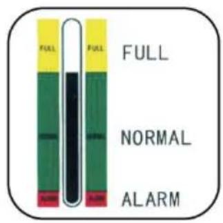
When the water level is below the green (normal) range of the water level, the cooling capacity of our chillers will drop slightly. Therefore, make sure that water level is in the green (normal) range. Pumps are strictly forbidden by circulating drainage!
- PLEASE MAKE SURE THE AIR INLET AND OUTLET ARE WELL VENTILATED!
The air outlet from the obstacle to the back of the cooler must be at least and it should be at least 8 cm between the obstacle and the side air intake
6. THE FILTER MUST BE CLEANED REGULARLY!
The dust meter must be unlocked and cleaned, otherwise it will cause serious clogging failure to the cooler.
7. PAY ATTENTION TO THE EFFECT OF CONDENSATE!
As the ambient humidity increases, when the water temperature is lower than ambient temperature, condensate will create circular pipes and cooling parts on the water surface. If this occurs, it is recommended to set a higher water temperature or keep the connected pipes and cooling components warm.
PROFESSIONAL USE ONLY!
This device must not be used by a child or a person with physical, sensory, physical, sensory, or physical impairments, or lack of experience and knowledge unless supervision or instruction is given, and the child is not allowed to place electrical appliances!
The circulating water of the water cooler must use a sealed container for no use, such as laser tube cooling water. Unsealed containers cannot circulate, so as water basins, buckets cannot be used for circulating water cooling with water coolers.
SPECIFICATIONS
| Model | CW-6000 | |
| voltage | AC220-240V | AC120V |
| frequency | 50Hz | 60Hz |
| power | 1500W | |
| Cooling capacity | 3.2kw | 3.5kw |
| Refrigerant | R410a | |
| noises | ≤80dB | |
| Water tank capaci | 15L | |
| Maximum flow | 65L/min | |
| Pump power | 370W | 600W |
| The main materia | Iron, copper | |
| Security | Compressor overcurrent protection flow alan overtemperature alarm | |
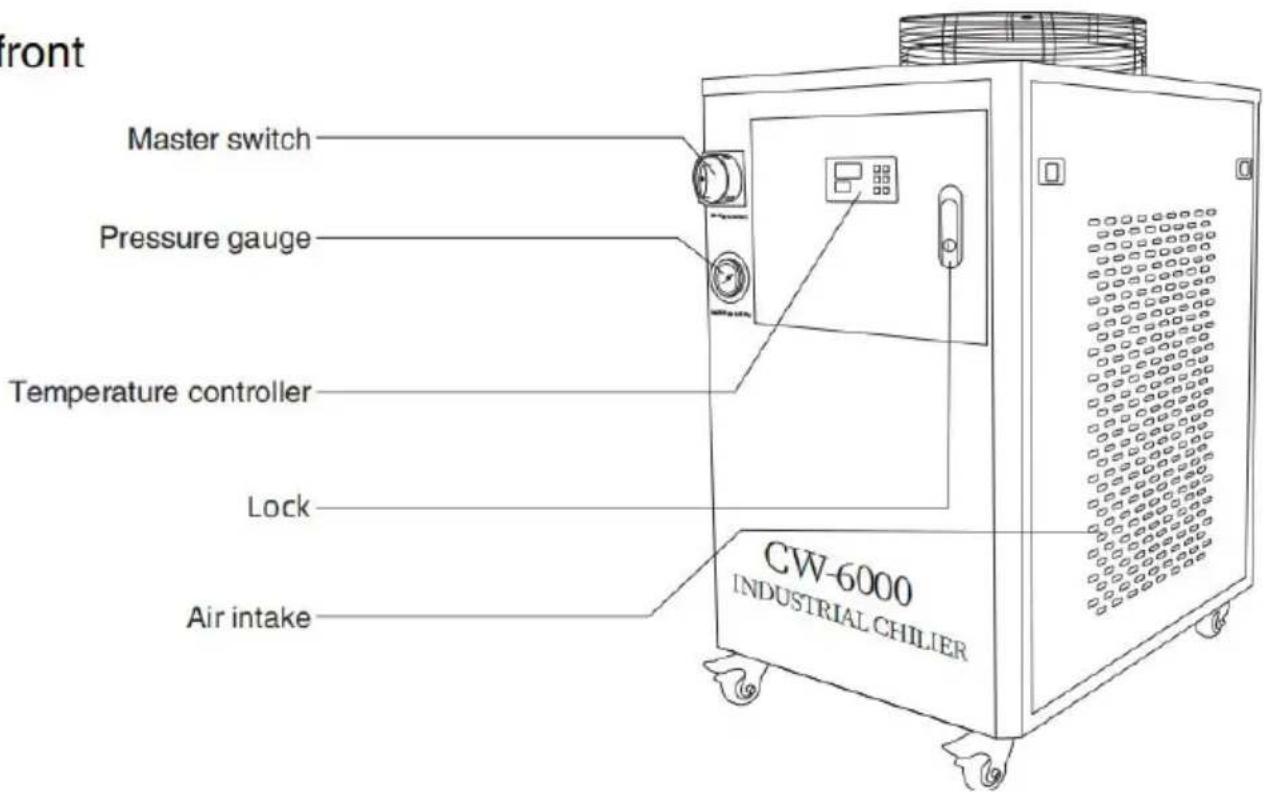
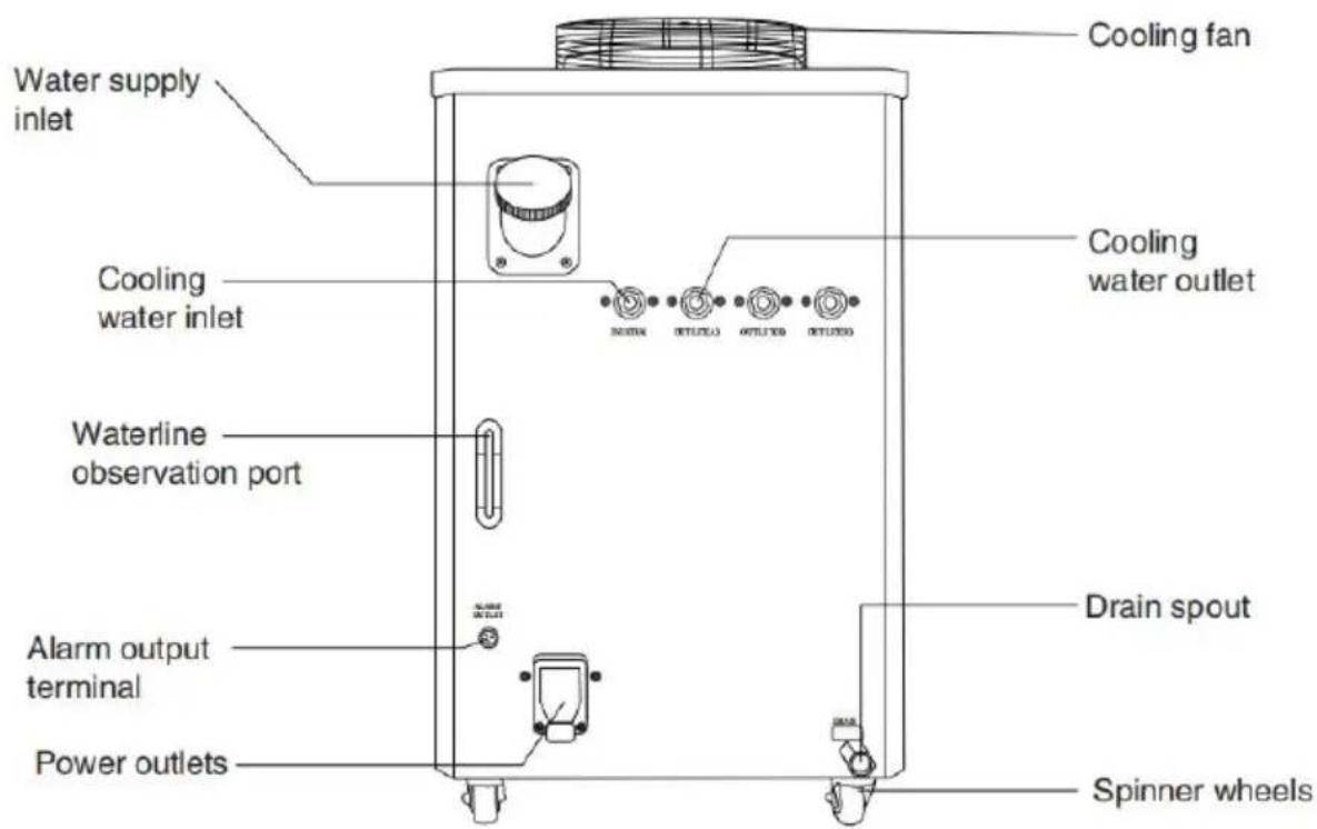
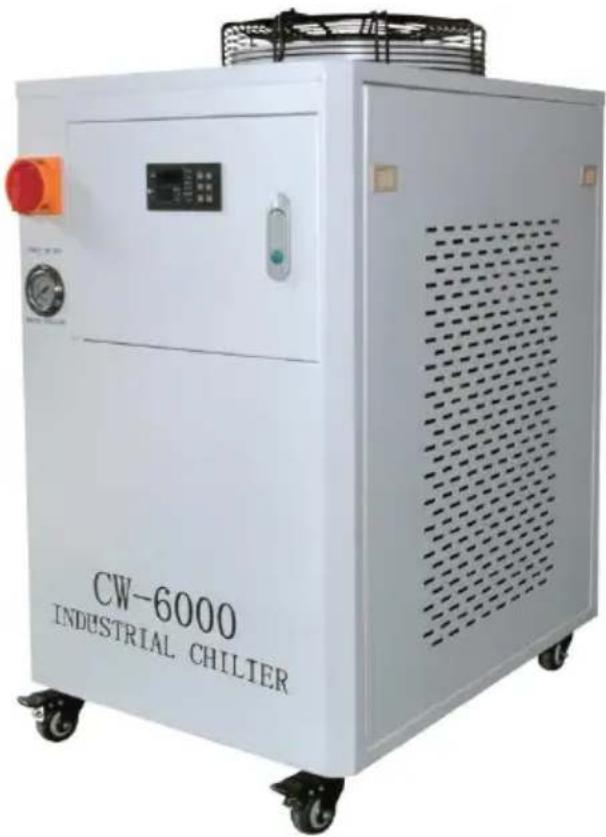
DEVICE ILLUSTRATION
front
behind
PROCEDURE
Installing this industrial chiller is very simple.
The first installation of a new machine can be carried out by following steps:
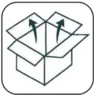 | 1.OPEN THE PACKAGE TO CHECK IF THE MACHINE IS FIXED AND ALL NECESSARY ACCESSORIES ARE COMPLETE. |
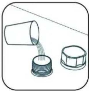 | 2.OPEN THE WATER SUPPLY INLET TO SU COOLING WATER (DON'T SPILL THE WATER OUT!).Observe the water level gauge and add water taking care not to let the water overflow! For cooling of carbon steel equipment, an appropriate amount of cooling water additive (anti-corrosion aqua) should be added to the water. Users in regions should use non-corrosive antifreeze. |
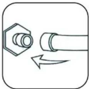 | 3.CONNECT THE INLET AND OUTLET PIPES ACCORDING TO THE SYSTEM CONDITIONS. |
| 4.PLUG IN THE POWER SUPPLY AND TURN ON THE POWER SWITCH. (DON'T START WITHOUT WATER IN THE TANK!) (1) The power switch is turned on and the circulating pump of t starts to work. The first operation may cause more bubbles in th causing occasional alarms for traffic, but after a few minutes of will return to normal.(2) After the first start-up, the water pipe must be checked for le immediately.(3) The power supply is turned on, if the water temperature is lo the set value, it is normal that the fan and other parts of the m | |
work. The temperature controller will automatically control the work state of compressor solenoid valves, fans and other components a to the set control parameters.
(4) Since the restart of the compressor and other components take time, depending on different conditions, the time varies from a few to a few minutes, so do not turn off the power frequently and to again.
⑤.CHECK THE WATER LEVEL IN THE TANK. The first start of the new cooler drains the air water pipe, causing a slight drop in the water but in order to maintain the water level in the area, it is allowed to add enough water again. observe and record the current water level, che again after the chiller has been running for a time, and if the water level drops significantly, please re-check the leakage of the water pipe.
⑥.ADJUST THE TEMPERATURE CONTROLLER PARAMETERS. CW-5000/5200 series uses intelligent thermostats. Usually the user not need to adjust it. If it is really necessary. See "Operating sta parameter tuning".
DISPLAY PANEL AND BUTTONS
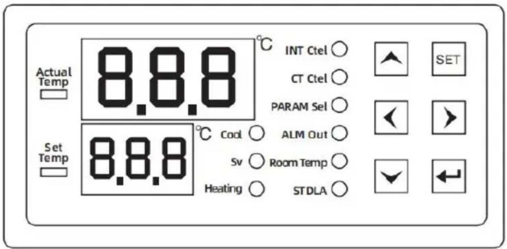
▲key:Move the up key
▼key:Move the key down
key:Left key
key:Right key
SETkey:Set the key
← key:Enter
(1) The display board can display six digits and nine status indicators (compressor-comp, solenoid valve-solenoid valve, electric heating
rod-heating, intelligent mode-INT ctrl, constant temperature mode-CT ctrl parameter setting-PARAM set, alarm output-ALM output, room temperature-room temp, start-up delay-ST delay).
Under normal operation, the upper display window displays the normal water temperature, and the lower display window displays the set water temperature.
(2) Description of display symbols:
| LIGHT | STATE | STATE | FUNCTION OR MEANING |
| Compressor indicator | Comp | bright | Compressor starts |
| extinguish | The compressor is turned off | ||
| Refrigerant solenoid valve indicator | Solenold valve | bright | The refrigerant solenoid valve is active |
| extinguish | The refrigerant solenoid valve is close | ||
| Heating rod indicator | heating | bright | The heating rod starts |
| extinguish | The heating rod is turned off | ||
| Intelligent control mode | INT ctrl | bright | The controller works in intelligent control mode |
| extinguish | The controller works in non-intelligent control mode | ||
| Thermostatic mode | CT ctrl | bright | The controller works in thermostatic mode |
| extinguish | The controller operates in non-thermost control mode | ||
| Parameter setting mode | PARAM set | bright | The controller works in parameter settings mode |
| extinguish | The controller operates in non-parametric mode | ||
| Alarm output mode | ALM output | bright | Alarm output status |
| extinguish | Non-alarm output status | ||
| Displays the room temperature status | Room temp | bright | Displays the room temperature status |
| extinguish | Displays a non-room temperature state | ||
| Boot delay status | ST delay | bright | The boot delay state is in |
| extinguish | The device is in the non-boot delay |
KEY PRESS INSTRUCTIONS
| DIGIT | KEYSTROKE | FUNCTION | DESCRIPTION OF THE OPERATION |
| 1 | SET+Enter | Manufacturer parameter adjustment | Press and hold the Enter key and the SET key, "99" will be displayed after three seconds, press the ▲▼ key to modify the password "XX" of the fact settings, press the SET key to enter the menu set you can modify the factory settings, and you can the (F0-A11) parameters. Press the Enter key any save the modified parameters, exit the parameter state, return to the temperature display, and run at to the new parameters. If no button is pressed with seconds, the controller will automatically exit the parameter setting state and will not save the mode parameters. If the password is incorrect, press SET return to the temperature display |
| 2 | ▲+SET | User parameter adjustments | 1.▲▽ Key change parameter value, key change parameter item, ◀ ► enter key save exit.2. Press and hold the ▲ key first, and then press button at the same time for five seconds The upp window displays "00", and the lower display window displays "PAS", at this time, press the ▲▼ key to the password that has been set, and then press SET key, if the password is correct, the lower display window displays the parameter item F0, and upper display window displays the parameter value and enters the setting state, indicating that the cor now in the parameter setting state. If the password incorrect, the temperature display will be returned, entering the setting state, press the left and right change the parameter item in turn, and press the to change the parameter value of the parameter it. Press the enter key at any time, save the modifie parameters, exit the parameter setting state, return temperature display, and run according to the new parameters. If no button is pressed within 20 sec controller will automatically exit the parameter setting and will not save the modified parameters. In the parameter setting, pressing SET does not respond |
| 3 | ▲+▼ | Quickly restore factory settings | When the power is on and the normal display, with tempera-ture is not set, press and hold the ▲▼ the same time, the thermostat will be powered on "rE" will be displayed after three seconds, and all values will be restored to the factory value, and to normal working state after 3 seconds. |
| 4 | ▼ | Check room temperature | In the non-set state, press the ▽ key to display detection value of the room temperature sensor, and resume the display of water temperature after 6 set (at this time, the room temp light is on, indicating upper window is displayed as room temperature) |
| 5 | SET | Quick adjustments | Press the SET button when the thermostat is work normally, if the thermostat is working in constant temperature mode, the panel will display the parameter value of F0 (set temperature), and the parameter of F1 (temperature difference value) will be displayed in the smart mode (at this time, the parameter set light will be on, indicating that the controller is now setting the parameter state). At the time, press the ▲▼ key to modify the setting value then press the SET key to exit or exit without press button within 20 seconds. If you press the enter key save the disk and exit, the new parameters will take it |
MENU DESCRIPTION
| code | SET UP THE PROJECT | RANGE | DEFAULT VALUE | REMARK |
| F0 | Set the temperature | F9~F8/-20~40 | 25.0 | Smart temperature control mc constant temperature mode |
| F1 | Temperature difference value | -15~5 | -2 | |
| F2 | Refrigeration regression | 0.1~9.0 | 0.8 | |
| F3 | Control mode | 0~1 | 1 | 1 Smart, 0 Constant Temperature |
| F4 | Water temperature super high alarm | 1~80 | 10 | |
| F5 | Water temperature ultra-low ala | 1~40 | 15 | |
| F6 | Temperature super high alarm | 40~50 | 45 | |
| F7 | password | 00~99 | 06 | |
| F8 | Maximum set water temperature | (F9+1)~50 | 30 | |
| F9 | Minimum set water temperature | -30~ (F8-1) | 20 | |
| A0 | Heating back | 0.1~5.0 | 0.5 | |
| A1 | Start-up alarm delay | 0~30 | 5 | minute |
| A2 | Boot delay | 10~300 | 15 | second |
| A3 | State transition delay | 0~99 | 5 | second |
| A4 | Room temperature calibration | -10.0~10.0 | 0 | |
| A5 | Water temperature temperature correction | -10.0~10.0 | 0 | |
| A6 | System coefficient of inertia | 0~40 | 08 | The smaller the value the more accurate it is |
| A7 | Compressor start-up protection | 0~300 | 30 | second |
| A8 | The electric heating rod contro the regression | -5.0~20.0 | 0.2 | temperature< F0-A8 works temperature>F0-A8 stops working |
| A9 | The input signal is delayed | 0~99 | 2 | second |
| A10 | The input signal is normally o and normally closed | NO/NC | NC | NO is normally open NC is normally closed |
| A11 | The solenoid valve opens with a delay | 0-4.0 | 0 | F0-A11 solenoid valve |
| A12 | E6 function when alarming | 0/1 | 0 | 0 is normal operation 1 is the system stop |
| A13 | The external alarm output is delayed in recovery | 0~99 | 2 | second |
| A14 | The compressor starts the solenoid valve and closes it fo delayed time | 0~30 | 0 | second |
| A15 | ER1-ER5 signal relay alarm st | 0/1 | 0 | 1 output/0 no output |
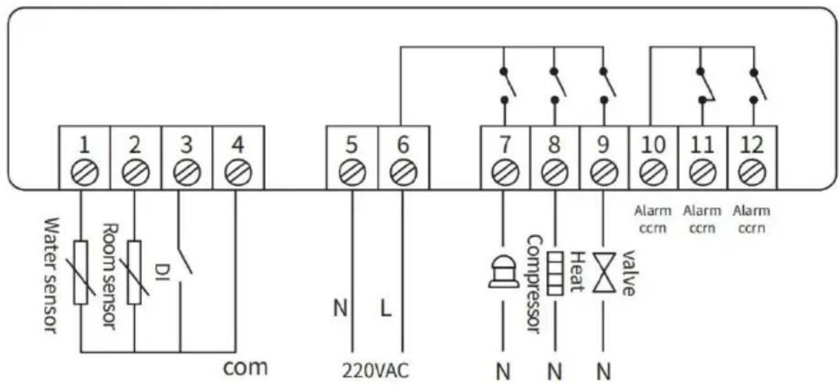
CONTROLLER WIRING DIAGRAM
RY1001A
flowchart
graph TD
    A["1"] --> B["2"]
    B --> C["3"]
    C --> D["4"]
    E["Water sensor"] --> F["Room sensor"]
    F --> G["DI"]
    G --> H["com"]
    I["N"] --> J["L"]
    K["220VAC"] --> L["7"]
    M["220VAC"] --> N["8"]
    O["220VAC"] --> P["9"]
    Q["220VAC"] --> R["10"]
    S["220VAC"] --> T["11"]
    U["220VAC"] --> V["12"]
    W["Compressor"] --> X["Heat Valve"]
    Y["Alarm ccrn"] --> Z["Alarm ccrn"]
    AA["Alarm ccrn"] --> AB["Alarm ccrn"]
Notice
-
Strictly distingulsh the wiring terminal of the relay, sensor and power supply.
-
The wiring of sensor and power supply should be kept in a proper distance.
Note:
①. Strictly distinguish the wiring of power supply, relay output and sen and the relay should not be overloaded.
②. All wiring changes must be made with the power supply disconnect
③. This controller is forbidden to be used in water or excessively hum environments, and is prohibited from being used in high temperatures, strong electromagnetic interference, and strong environments.
④. Ensure that the power supply voltage is consistent with the voltage marked on the controller, and ensure the stability of the power supply voltage;
CONTROL THE OUTPUT FUNCTION
- REFRIGERATION CONTROL:
| CHILLER WORKING CONDITION | COMPRESSOR CONDITION | REFRIGERANT SOLENOID VALVE WORKING CONDITION | HEATING ROD WORKING CONDITION | REMARK |
| refrigeration | running | end | Stop it | 100% full power refrigeration |
| One-stage micro refrigeration | running | Conduction | Stop it | 40% power refrigeration |
| Two-stage micro-cooling | running | Conduction | initiate | 20% power refrigeration heating rod work |
| heating | Stop it | Conduction | initiate | No refrigeration, only heating |
The above are the four working states of the chiller controlled by the thermostat. The shortest transition time between refrigeration and micro-cooling is (about 5-10 seconds) and can be changed multiple tir in one minute.
If the heat load is turned on, the chiller mainly works in these two conditions, and the temperature of the cooling water can be precisely controlled. (The water temperature fluctuates around 0.3 degrees Celsius during the actual test.) When the heat load is turned off, the water temperature is overshooted downward, and when the A0 set value is reached, the refrigeration compressor stops working.
It is important to note that; There will be a time difference between conversion of the chiller working condition and the change of water temperature, and the parameter A6 is the relevant parameter that describes the inertia of the system, according to this parameter, the controller can calculate the corresponding action advance, reduce the overshoot of the water temperature.
- When the compressor is working, when the temperature is reduced (equal to, below) the set value of the water temperature, and the duration of the refrigerant solenoid valve has been greater than the time set by the state transition delay (A3), the refrigerant solenoid valve is turned on. When the temperature rises above (higher) the water temperature set value, and the conduction duration of the refrigerant solenoid valve is greater than the time set by the state transition del the refrigerant solenoid valve is cut off.
- When the compressor stops running, the refrigerant solenoid valve turned on.
- When the compressor starts to work (when starting), the refrigerant solenoid valve must be in the cut-off state
(under normal circumstances, this condition is satisfied).
ELECTRIC HEATING RODS
When the water temperature is lowered below the water temperature point - the electric heating rod controls the difference, the electric heat rod starts to work. When the water temperature rises to higher than water temperature set value - the electric heating rod controls the difference, the electric heating rod stops working.
2. WATER TEMPERATURE SETPOINT:
When the thermostat is operating in constant temperature mode, the V temperature setting value is constant at F0 just like a normal thermos When the thermostat is in smart mode, the water temperature setting varied.
SMART MODE SETPOINT
When the room temperature plus F1 is less than F9, the water temp set value is equal to F9
When the room temperature plus F1 is greater than F8, the water temperature setting value is equal to F8
When the room temperature plus F1 is less than, equal to F8, greater or equal to F9, the water temperature setting value is equal to room temperature + F1
3. ALARM CODE AND CONTROL LOGIC:
| CODE | CONTENT | ALARM CONDITIONS |
| Er1 | The room temperature is too high | Room temperature > temperature ultra-high alarm value setting value) |
| Er2 | The water temperature i too high | Water temperature> set temperature + refrigeration difference F2 + water temperature super high alarm F |
| Er3 | The water temperature i too low | Water temperature< set temperature - heating return difference A0 - water temperature ultra-low alarm F5 |
| Er4 | Room temperature senso failure | Room temperature sensors are short-circuited or open-circuited |
| Er5 | The water temperature sensor is faulty | The water temperature sensor is short-circuited or open-circuited |
| Er6 | External input alarms | The external connection is lost |
| Er2 and Er3 will only be effective when the water temperature enters the target tempe (i.e., between the set temperature and the set temperature + refrigeration difference F2) satisfying the start-up alarm delay (A1) or after powering on and forced cooling for 30 | ||
(1) THE CONTROL STATE WHEN THE ALARM IS GENERATED
When the Er3 alarm occurs, the refrigeration and heating relays operate acco to normal logic.
When the Er4 alarm occurs, the water temperature setting (F0) of the control runs according to the factory setting. (If the controller works in constant temperature mode, E4 does not alarm)
In the event of an Er5 alarm, the system should be shutdown regardless of state in which it is running.
(2) ALARM STOP SOUND
In the alarm state of the thermostat, press any button to stop the alarm but the alarm display will not stop until the alarm condition is eliminated.
(3) EXTERNAL INPUT ALARM:
After the external input alarm signal and the time of delay setting A9 is sati Er6 is displayed, the system control is not affected, and the alarm buzzer so
(4)When Er1-Er6 appears, the alarm buzzer sounds, and when the silencer a key is pressed, the buzzer stops ringing. Alarm output, relay and other faults automatically reset after they are removed.
(5)When Er1-Er6 appears, the alarm buzzer sounds, and when the silencer a
key is pressed, the buzzer stops ringing. Alarm output, relay and other faults automatically reset after they are removed.
1. KEY TONE
There is a key prompt when the controller button is pressed, and a short to prompt when each button is pressed.
2. POWER-ON ID
After powering on, the display flashes for 3 seconds, and the indicator light digital tube are displayed at the same time, and the buzzer enters the normal operation state after the sound.
3. TEMPERATURE CORRECTION
Room temperature calibration and water temperature calibration, when the displayed temperature (room temperature and water temperature) is deviated from the actual temperature, A4 and A5 can be adjusted for correction.
4. POWER-ON PROCESSING
After the power-on delay (A2) time passes after the thermostat is powered on thermostat enters the 100% full-power cooling state for 25 seconds. Then cor the chiller to work according to the actual air temperature and water tempera (Note: This is the "Forced Refrigeration on Boot" function.) If the water temperature is higher than the water temperature setpoint-heating backdrop, the compressor does not need to stop after the forced refrigeration is turned on. function is designed to facilitate maintenance work)
Manufacturer: Shanghaimuxinmuyeyouxiangongsi
Address: Shuangchenglu 803nong11hao1602A-1609shi, baoshanqu, shanghai 200000 CN.
Imported to AUS: SIHAO PTY LTD, 1 ROKEVA STREETEASTWOOD NSW 2122 Australia
Imported to USA: Sanven Technology Ltd., Suite 250, 9166 Anaheim Place, Rancho Cucamonga, CA 91730
| EC | REP |
E-CrossStu GmbH
Mainzer Landstr.69, 60329 Frankfurt am Ma
| UK | REP |
YH CONSULTING LIMITED.
C/O YH Consulting Limited Office 147, Centurion H
London Road, Staines-upon-Thames, Surrey, TW18 4
VEVOR®
TOUGH TOOLS, HALF PRICE
Technical Support and E-Warranty Certificate
www.vevor.com/support
VEVOR®
TOUGH TOOLS, HALF PRICE
We continue to be committed to provide you tools with competitive price. "Save Half", "Half Price" or any other similar expressions used by us only represent estimate of savings you might benefit from buying certain tools with us compared top brands and does not necessarily mean to cover all categories of tools offered are kindly reminded to verify carefully when you are placing an order with us actually saving half in comparison with the top major brands.
MODÈLE : CW-6000

NEED HELP? CONTACT US!
Have product questions? Need technical support? Please feel fr contact us:
Technical Support and E-Warranty Certificate www.vevor.com/support
This is the original instruction, please read all manual instruction carefully before operating. VEVOR reserves a clear interpretation user manual. The appearance of the product shall be subject to product you received. Please forgive us that we won't inform you there are any technology or software updates on our product.

PROCEDURE
⑤.VÉRIFIEZ LE NIVEAU D'EAU DANS LE RÉSERVOIR.
-
Strictly distingulsh the wiring terminal of the relay, sensor and power supply.
-
The wiring of sensor and power supply should be kept in a proper distance.
Note:
C/O YH Consulting Limited Office 147, Centurion H London Road, Staines-upon-Thames, Surrey, TW18 4
VEVOR®
TOUGH TOOLS, HALF PRICE
www.vevor.com/support
INDUSTRIELLER WASSERKÜHLER BENUTZERHANDBUCH
MODELL: CW-6000
We continue to be committed to provide you tools with competitive price. "Save Half", "Half Price" or any other similar expressions used by us only represent estimate of savings you might benefit from buying certain tools with us compared top brands and does not necessarily mean to cover all categories of tools offered are kindly reminded to verify carefully when you are placing an order with us actually saving half in comparison with the top major brands.
MODELL: CW-6000

NEED HELP? CONTACT US!
Have product questions? Need technical support? Please feel fr contact us:
Technical Support and E-Warranty Certificate www.vevor.com/support
This is the original instruction, please read all manual instruction carefully before operating. VEVOR reserves a clear interpretation user manual. The appearance of the product shall be subject to product you received. Please forgive us that we won't inform you there are any technology or software updates on our product.

PROCEDURE
-
Strictly distingulsh the wiring terminal of the relay, sensor and power supply.
-
The wiring of sensor and power supply should be kept in a proper distance.
Notiz:
C/O YH Consulting Limited Office 147, Centurion H London Road, Staines-upon-Thames, Surrey, TW18 2
VEVOR®
TOUGH TOOLS, HALF PRICE
www.vevor.com/support
VEVOR®
TOUGH TOOLS, HALF PRICE
We continue to be committed to provide you tools with competitive price. "Save Half", "Half Price" or any other similar expressions used by us only represent estimate of savings you might benefit from buying certain tools with us compared top brands and does not necessarily mean to cover all categories of tools offered are kindly reminded to verify carefully when you are placing an order with us actually saving half in comparison with the top major brands.
MODELLO: CW-6000

NEED HELP? CONTACT US!
Have product questions? Need technical support? Please feel fr contact us:
Technical Support and E-Warranty Certificate www.vevor.com/support
This is the original instruction, please read all manual instruction carefully before operating. VEVOR reserves a clear interpretation user manual. The appearance of the product shall be subject to product you received. Please forgive us that we won't inform you there are any technology or software updates on our product.
WARN
PROCEDURE
-
Strictly distingulsh the wiring terminal of the relay, sensor and power supply.
-
The wiring of sensor and power supply should be kept in a proper distance.
Nota:
SETPOINT DELLA MODALITÀ SMART
Importato in AUS: SIHAO PTY LTD, 1 ROKEVA STREETEASTWOOD NSW 2122 Australia
C/O YH Consulting Limited Office 147, Centurion H London Road, Staines-upon-Thames, Surrey, TW18 4
VEVOR®
TOUGH TOOLS, HALF PRICE
www.vevor.com/support
VEVOR®
TOUGH TOOLS, HALF PRICE
We continue to be committed to provide you tools with competitive price. "Save Half", "Half Price" or any other similar expressions used by us only represent estimate of savings you might benefit from buying certain tools with us compared top brands and does not necessarily mean to cover all categories of tools offered are kindly reminded to verify carefully when you are placing an order with us actually saving half in comparison with the top major brands.
MODELO: CW-6000

NEED HELP? CONTACT US!
Have product questions? Need technical support? Please feel fr contact us:
Technical Support and E-Warranty Certificate www.vevor.com/support
This is the original instruction, please read all manual instruction carefully before operating. VEVOR reserves a clear interpretation user manual. The appearance of the product shall be subject to product you received. Please forgive us that we won't inform you there are any technology or software updates on our product.

PROCEDURE
-
Strictly distingulsh the wiring terminal of the relay, sensor and power supply.
-
The wiring of sensor and power supply should be kept in a proper distance.
Nota:
Importado a AUS: SIHAO PTY LTD, 1 ROKEVA STREETEASTWOOD NSW 2122 Australia
Importado a EE. UU.: Sanven Technology Ltd., Suite 250, 9166 Anal Place, Rancho Cucamonga, CA 91730
| EC | REP |
E-CrossStu GmbH
Mainzer Landstr.69, 60329 Frankfurt am Ma
| UK | REP |
YH CONSULTING LIMITED.
C/O YH Consulting Limited Office 147, Centurion H
London Road, Staines-upon-Thames, Surrey, TW18 4
VEVOR®
TOUGH TOOLS, HALF PRICE
www.vevor.com/support
VEVOR®
TOUGH TOOLS, HALF PRICE
www.vevor.com/support
PRZEMYSŁOWY AGREGAT WODY LODOWEJ INSTRUKCJA OBSŁUGI
MODEL: CW-6000
We continue to be committed to provide you tools with competitive price. "Save Half", "Half Price" or any other similar expressions used by us only represent estimate of savings you might benefit from buying certain tools with us compared top brands and does not necessarily mean to cover all categories of tools offered are kindly reminded to verify carefully when you are placing an order with us actually saving half in comparison with the top major brands.
MODEL: CW-6000

NEED HELP? CONTACT US!
Have product questions? Need technical support? Please feel fr contact us:
Technical Support and E-Warranty Certificate www.vevor.com/support
This is the original instruction, please read all manual instruction carefully before operating. VEVOR reserves a clear interpretation user manual. The appearance of the product shall be subject to product you received. Please forgive us that we won't inform you there are any technology or software updates on our product.

PROCEDURE
1.Strtctly dlstlngulsh the wiring terminal of the relay, sensor and power supply.
- The wiring of sensor and power supply should be kept in a proper distance.
Notatka:
- KOD ALARMOWY I LOGIKA STEROWANIA:
Import do AUS: SIHAO PTY LTD, 1 ROKEVA STREETEASTWOOD N 2122 Australia
Import do USA: Sanven Technology Ltd., Suite 250, 9166 Anaheim F Rancho Cucamonga, CA 91730
| EC | REP |
E-CrossStu GmbH
Mainzer Landstr.69, 60329 Frankfurt am Ma
| UK | REP |
YH CONSULTING LIMITED.
C/O YH Consulting Limited Office 147, Centurion H
London Road, Staines-upon-Thames, Surrey, TW18 4
VEVOR®
TOUGH TOOLS, HALF PRICE
www.vevor.com/support
VEVOR®
TOUGH TOOLS, HALF PRICE
Technisch Ondersteuning en e-garantiecertificaat www.vevor.com/support
INDUSTRIËLE WATERKOELER HANDLEIDING
MODEL: CW-6000
We continue to be committed to provide you tools with competitive price. "Save Half", "Half Price" or any other similar expressions used by us only represent estimate of savings you might benefit from buying certain tools with us compared top brands and does not necessarily mean to cover all categories of tools offered are kindly reminded to verify carefully when you are placing an order with us actually saving half in comparison with the top major brands.
MODEL: CW-6000

NEED HELP? CONTACT US!
Have product questions? Need technical support? Please feel fr contact us:
Technical Support and E-Warranty Certificate www.vevor.com/support
This is the original instruction, please read all manual instruction carefully before operating. VEVOR reserves a clear interpretation user manual. The appearance of the product shall be subject to product you received. Please forgive us that we won't inform you there are any technology or software updates on our product.

PROCEDURE
⑤.CONTROLEER HET WATERNIVEAU IN DE TANK.
1.Strtctly dlstlngulsh the wiring terminal of the relay, sensor and power supply.
- The wiring of sensor and power supply should be kept in a proper distance.
Opmerking:
3. ALARMCODE EN BEDIENINGSLOGICA:
(3) EXTERN INGANGALARM:
Anaheim Place, Rancho Cucamonga, CA 91730
| EC | REP |
E-CrossStu GmbH
Mainzer Landstr.69, 60329 Frankfurt am Ma
| UK | REP |
YH CONSULTING LIMITED.
C/O YH Consulting Limited Office 147, Centurion H
London Road, Staines-upon-Thames, Surrey, TW18 4
VEVOR®
TOUGH TOOLS, HALF PRICE
www.vevor.com/support
VEVOR®
TOUGH TOOLS, HALF PRICE
www.vevor.com/support
INDUSTRIELL VATTENKYLARE ANVÄNDARMANUAL
MODELL: CW-6000
We continue to be committed to provide you tools with competitive price. "Save Half", "Half Price" or any other similar expressions used by us only represent estimate of savings you might benefit from buying certain tools with us compared top brands and does not necessarily mean to cover all categories of tools offered are kindly reminded to verify carefully when you are placing an order with us actually saving half in comparison with the top major brands.
MODELL: CW-6000
NEED HELP? CONTACT US!
Have product questions? Need technical support? Please feel fr contact us:
Technical Support and E-Warranty Certificate www.vevor.com/support
This is the original instruction, please read all manual instruction carefully before operating. VEVOR reserves a clear interpretation user manual. The appearance of the product shall be subject to product you received. Please forgive us that we won't inform you there are any technology or software updates on our product.

PROCEDURE
1.Strictly distingulsh the wiring terminal of the relay, sensor and power supply.
2. The wiring of sensor and power supply should be kept in a proper distance.
Notera:
(3) EXTERN INPUT LARM:
C/O YH Consulting Limited Office 147, Centurion H
London Road, Staines-upon-Thames, Surrey, TW18 4
VEVOR®
TOUGH TOOLS, HALF PRICE
www.vevor.com/support