KH-6000 - Boiler Vevor - Free user manual and instructions
Find the device manual for free KH-6000 Vevor in PDF.

| Product Type | Industrial Water Chiller (Boiler) |
| Brand | Vevor |
| Model | KH-6000 |
| Dimensions (L x W x H) | 60 x 28.5 x 38 cm |
| Net Weight | 17 kg (220V) / 17.5 kg (110V) |
| Power Supply | AC 220V 50Hz / AC 110V 60Hz |
| Rated Power | 500 W |
| Cooling Capacity | 0.13 kW (220V) / 0.2 kW (110V) |
| Refrigerant | R134a |
| Noise Level | ≤ 65 dB |
| Water Tank Capacity | 12 L |
| Maximum Pump Flow Rate | 8 L/min |
| Pump Power | 30 W |
| Main Materials | Iron, copper |
| Color | Blue and white |
| Safety | Compressor overcurrent protection, flow alarm, overheat alarm |
| Main Functions | Closed-loop water cooling, temperature regulation via intelligent thermostat, flow and overheat alarm |
| Maintenance and Cleaning | Clean dust filter regularly, keep water level in green zone, check for leaks, use antifreeze in cold regions |
| Spare Parts and Repairability | Contact technical support via www.vevor.com/support for parts and repairs |
| General Information | Professional use only, do not use by children or untrained persons, requires sufficient ventilation (air outlet clearance of 30 cm, side inlet clearance of 8 cm) |
Frequently Asked Questions - KH-6000 Vevor
User questions about KH-6000 Vevor
0 question about this device. Answer the ones you know or ask your own.
Ask a new question about this device
Download the instructions for your Boiler in PDF format for free! Find your manual KH-6000 - Vevor and take your electronic device back in hand. On this page are published all the documents necessary for the use of your device. KH-6000 by Vevor.
USER MANUAL KH-6000 Vevor
Technical Support and E-Warranty Certificate
www.vevor.com/support
INDUSTRIALWATERCHILLER USERMANUAL
MODEL: KH-6000
We continue to be committed to provide you tools with competitive price. "Save Half", "Half Price" or any other similar expressions used by us only represents an estimate of savings you might benefit from buying certain tools with us compared to the major top brands and does not necessarily mean to cover all categories of tools offered by us. You are kindly reminded to verify carefully when you are placing an order with us if you are actually saving half in comparison with the top major brands.
MODEL: KH-6000
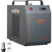
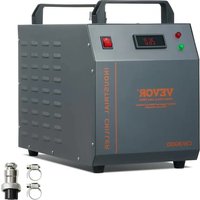
natural_image
White industrial machine with perforated ventilation slots and control panel (no visible text or symbols)(The picture is for reference only, please refer to the actual object)
NEEDHELP?CONTACTUS!
Have product questions? Need technical support? Please feel free to contact us:
TechnicalSupportandE-WarrantyCertificate
www.vevor.com/support
This is the original instruction, please read all manual instructions carefully before operating. VEVOR reserves a clear interpretation of our user manual. The appearance of the product shall be subject to the product you received. Please forgive us that we won't inform you again if there are any technology or software updates on our product.
WARN
PLEASE MAKE SURE THAT THE POWER SUPPLY AND THE POWER OUTLET ARE IN GOOD CONTACT AND THE GROUNDING WIRE MUST BE FIRM!
Although the average working current of the chiller is small, the instantaneous working current can sometimes reach 6\~10 amperes (the instantaneous working current of the AC110V power supply model is possible up to 10\~15 amperes)
PLEASE MAKE SURE THAT THE WORKING CHILLER HAS A STABLE AND NORMAL VOLTAGE!
Since the refrigeration compressor is more sensitive to power supply and voltage, so the working voltage our standard product is 220^A 240V (110V model is 110 120V), if you really need a wider operating voltage range, we can customize.
PLEASE MISMATCHED POWER FREQUENCY WILL CAUSE CHILLER DAMAGE!
Please select mode: 50Hz or 60Hz depending on the actual situation.
TO PROTECT THE PUMP, IT IS STRICTLY FORBIDDEN TO RUN THE CHILLER WITHOUT WATER IN THE STORAGE TANK!
The new machine is packed after draining the entire water in the tank, so please make sure that the tank has enough water and there is water inside the machine before starting, otherwise it is easy to damage the pump. When the water level is below the green (normal) range of the water level gauge, the cooling capacity of our chillers will drop slightly. Therefore, make sure that the water level is in the green (normal) range. Pumps are strictly forbidden by circulating drainage!
PLEASE MAKE SURE THE AIR INLET AND OUTLET ARE WELL VENTILATED!
The air outlet from the obstacle to the back of the cooler must be at least 30 cm, and it should be at least 8 cm between the obstacle and the side air intake.
THE FILTER MUST BE CLEANED REGULARLY!
The dust meter must be unlocked and cleaned, otherwise it will cause serious clogging failure to the cooler.
PAY ATTENTION TO THE EFFECT OF CONDENSATE!
As the ambient humidity increases, when the water temperature is lower than the ambient temperature, condensate will create circular pipes and cooling parts on the water surface. If this occurs, it is recommended to set a higher water temperature or keep the connected pipes and cooling components warm.
PROFESSIONAL USE ONLY!
This device must not be used by a child or a person with physical, sensory or physical, sensory, or physical impairments, or lack of experience and knowledge, unless supervision or instruction is given, and the child is not allowed to play with electrical appliances!
The circulating water of the water cooler must use a sealed container for normal use, such as laser tube cooling water. Unsealed containers cannot circulate, such as water basins, buckets cannot be used for circulating water cooling with water coolers.
| SPECIFICATIONS | ||
| Model KH-6000 | ||
| voltage | AC220V | AC110V |
| frequency | 50Hz | 60Hz |
| power | 500W | |
| Cooling capacity | 0.13kw 0.2kw | |
| Refrigerant | R134a | |
| noises | ≤65dB | |
| Water tank capacity | 12L | |
| Maximum flow | 8L/min | |
| Pump power | 30W | |
| The main material | Iron, copper | |
| Security | Compressor overcurrent protection flow alarm overtemperature alarm | |
| color | Blue-white | |
| net weight | 17kg | 17.5kg |
| gross weight | 21kg | 21.5kg |
| size | 60*28.5*38 (mm) | |
| Package size | 67.5*41.5*46.5 (mm) | |
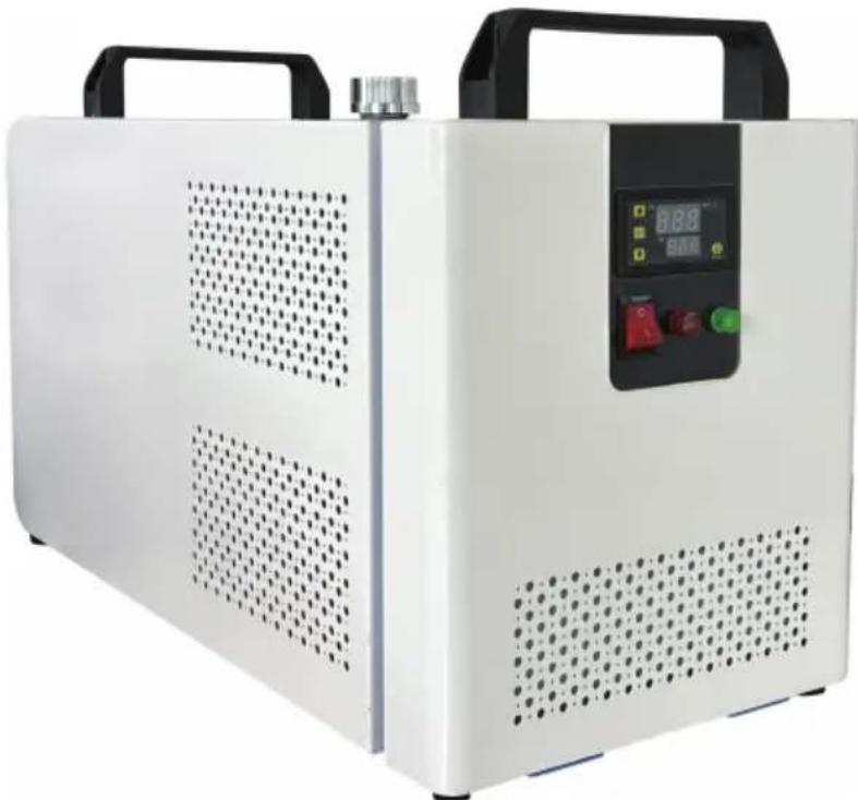
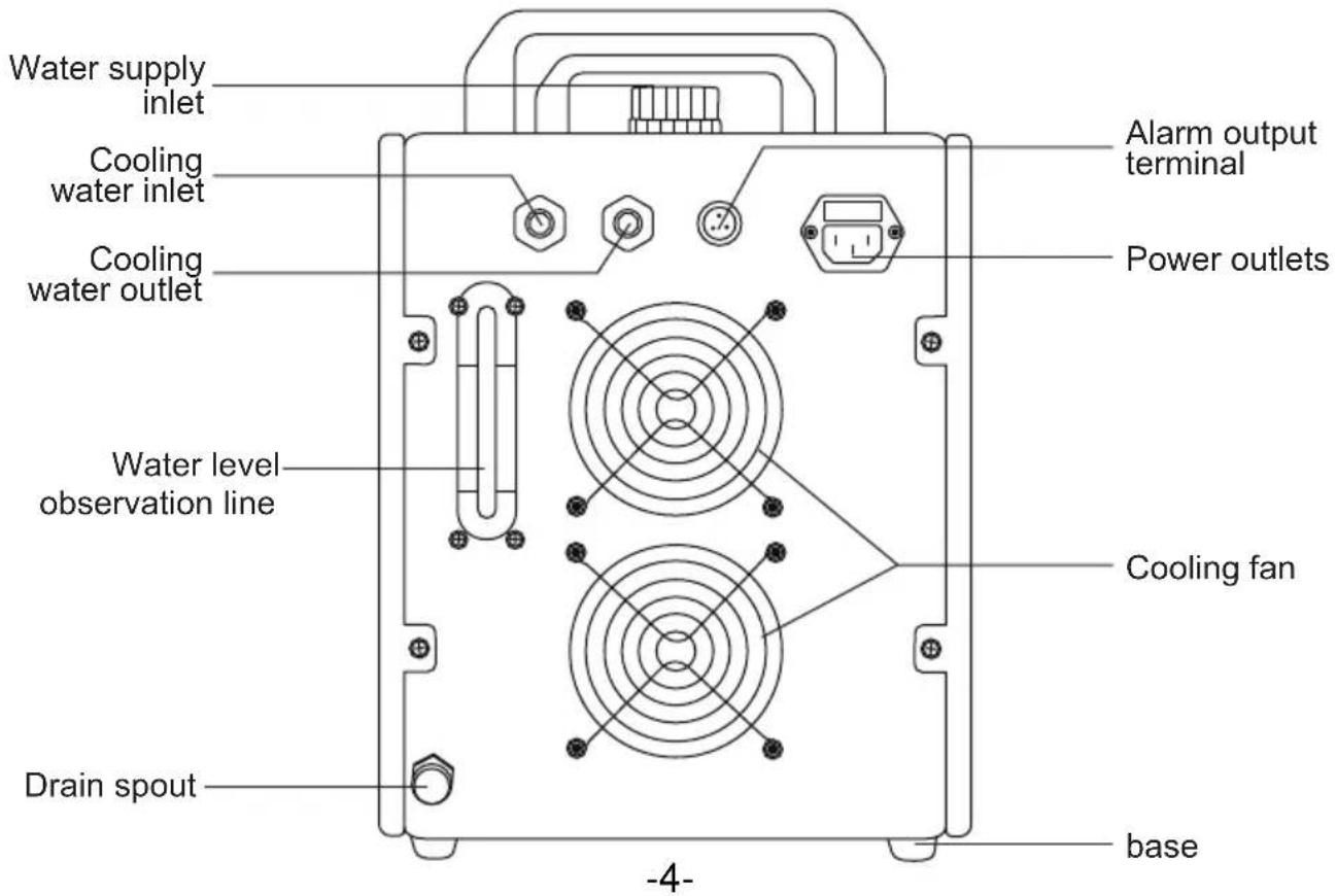
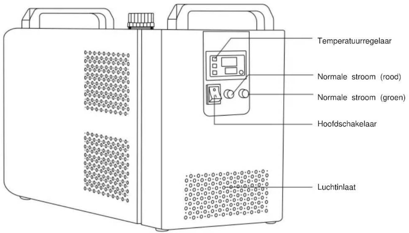
DEVICE ILLUSTRATION
front
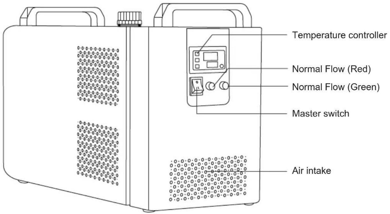
behind
PROCEDURE
Installing this industrial chiller is very simple.
The first installation of a new machine can be carried out by following these steps:
natural_image
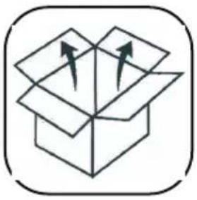
Simple line drawing of an open box with two arrows indicating direction (no text or symbols)①. OPEN THE PACKAGE TO CHECK IF THE MACHINE IS FIXED AND ALL NECESSARY ACCESSORIES ARE COMPLETE.
natural_image
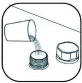
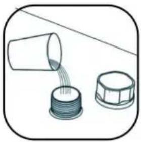
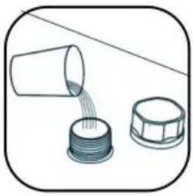
Illustration of a cup pouring liquid into a plastic container (no text or symbols)②. OPEN THE WATER SUPPLY INLET TO SUPPLY COOLING WATER (DON'T SPILL THE WATER OUT!).
Observe the water level gauge and add water slowly, taking care not to let the water overflow! For the cooling of carbon steel equipment, an appropriate amount of cooling water additive (anti-corrosion water aqua) should be added to the water. Users in cold regions should use non-corrosive antifreeze.
natural_image
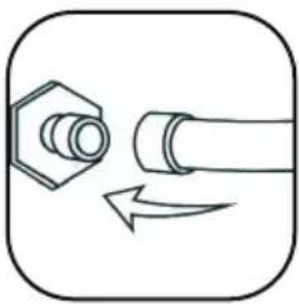
Simple line drawing of a bolt and pipe with directional arrows indicating movement (no text or symbols)③. CONNECT THE INLET AND OUTLET PIPES ACCORDING TO THE SYSTEM CONDITIONS.
④. PLUG IN THE POWER SUPPLY AND TURN ON THE POWER SWITCH. (DON'T START WITHOUT WATER IN THE TANK!)
(1) The power switch is turned on and the circulating pump of the chiller starts to work. The first operation may cause more bubbles in the pipe, causing occasional alarms for traffic, but after a few minutes of operation, it will return to normal.
(2) After the first start-up, the water pipe must be checked for leakage immediately.
(3) The power supply is turned on, if the water temperature is lower than the set value, it is normal that the fan and other parts of the machine do not work. The temperature controller will automatically control the working state of compressor solenoid valves, fans and other components according to the set control parameters.
(4) Since the restart of the compressor and other components takes a long time, depending on different conditions, the time varies from a few seconds to a few minutes, so do not turn off the power frequently and turn it on again.
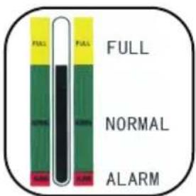
⑤.CHECK THE WATER LEVEL IN THE TANK.
The first start of the new cooler drains the air in the water pipe, causing a slight drop in the water level, but in order to maintain the water level in the green area, it is allowed to add enough water again. Please observe and record the current water level, check again after the chiller has been running for a period of time, and if the water level drops significantly, please re-check the leakage of the water pipe.
⑥.ADJUST THE TEMPERATURE CONTROLLER PARAMETERS.
CW-5000/5200 series uses intelligent thermostats. Usually the user does not need to adjust it. If it is really necessary. See "Operating status and parameter tuning".
DISPLAY PANEL AND BUTTONS
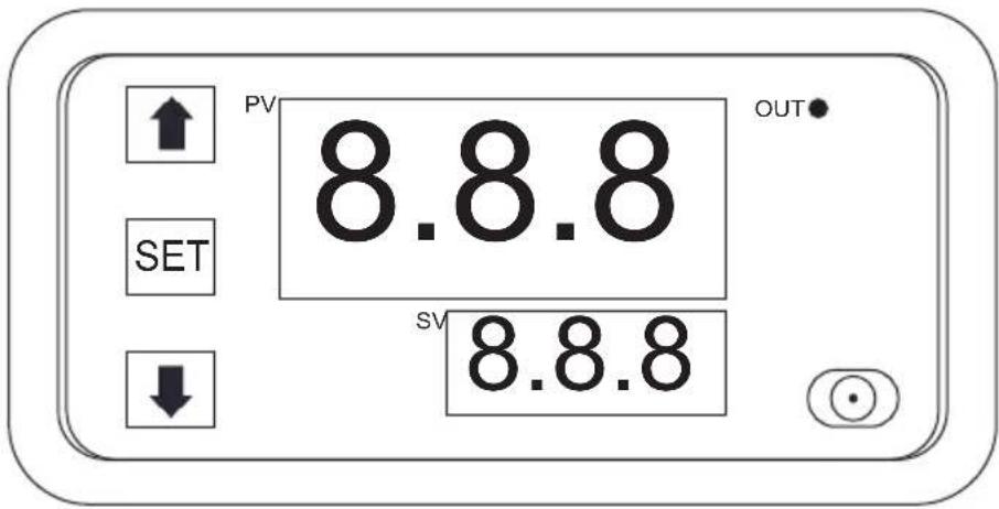
©key: Reboot key
↑ key: Adjust the up key
↓ key: Move the key down
SETkey: Set the key
INSTRUCTIONS FOR KEY OPERATION
Before use, the user is first reminded to pay attention to a point, the data must be set and wait for 6s, and the module will automatically save the data after 6s
| SORT KEYSTROKE FUNCTION | DESCRIPTION OF THE OPERATION | ||
| 1 | SET | Time setting mode | Press the SET button 1 time to enter the time setting mode, and the red digital tube flashes. Adjust the timing time T1 by pressing the key plus or subtracting the key button, T1 is set and short press SET again, the green digital tube flashes, the timing time is set by the key plus or minus T2, T2 time is set, short press the SET button again, the system will save the memory when setting the question or Yuan Shoufu 0s, O5B for the tracing brake to automatically remember and save the data. |
| 2 | ▲+SET | Parameterization mode | Press and hold SET to enter the parameter setting mode. There are two sets of parameters for users to select PO and P1. In the current mode, short press SET to switch between P0 and P1. Under the PO parameters, you can set the timing mode that suits you by pressing the button to add or subtract. Under the P1 parameter, the working mode can be set by pressing the button to add or subtract.P0--0: T1 timing time mode is secondsPO--1:T1 timing time mode is minutesPO--2: T1 timer time mode is timeP1--0: relay pick-up after delay T1 time (T1 timing) P1-1: relay release after delay T1 time (T1 timing) P1-2: relay pick-up after delay T1 time (T1 timing), relay release (T2 timing) after delay T2 time, end.P1--3: Relay release (T1 timing) after delay T1 time, relay engagement (T2 timing) after delay T2 time, and end.P1-a4: Relay engagement (T1 timing) after delay T1 time, relay release (T2 timing) after delay T2 time, and repeat cycle.P1--5: Relay release after delay T1 time (T1 timing), relay engagement after delay T2 time (T2 timing), repeat cycle.For example, for example, a customer needs to turn on the computer for 10 seconds, turn off it for 20 seconds, and keep looping.T1 setting time 10, T2 setting time 20PO-0 (T1 timing range is seconds)P1-5 (the working mode of the timer is to work first and then stop and keep looping) |
| 3 | SET | Factory reset | Due to the wrong setting, the data is messed up, and when it cannot be set, you can choose to restore the factory language and leave it on and then power it on. |
Wiring (Connecting Mode)
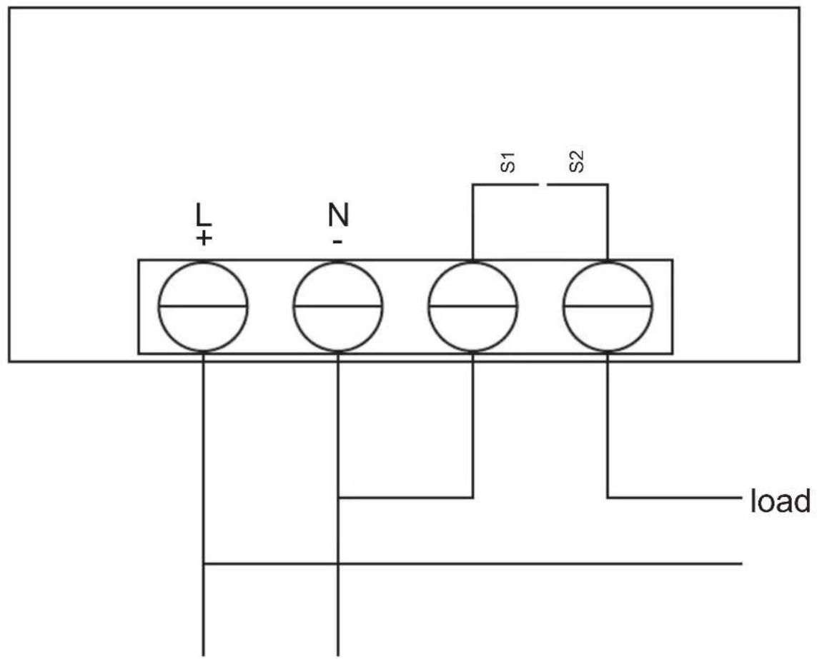
110V-220V Power supply (Suupply)
RELAYS ARE AVAILABLE IN 3 OPERATING VOLTAGE SPECIFICATIONS:
DC 12V/DC 24V/AC 110V-220V 2200W
You can choose to buy according to your actual situation, and if you don't know how to wire or don't know how to choose, you can contact customer service for advice
PRODUCT INTRODUCTION:
Time range: 0-999 hours/0-999 minutes/0-999 seconds
Display panel size: 79mm*43mm
Installation size: 71mm*40mm*24mm
Features: 18 combinations of time can be set
Relay: Original 20A relay, power < 1800W
Working voltage: DC 12V / DC 24V / AC 110V-220V (optional)
VEVOR®
TOUGH TOOLS, HALF PRICE
TechnicalSupportandE-WarrantyCertificate www.vevor.com/support
VEVOR®
TOUGH TOOLS, HALF PRICE
Assistance technique et certificat garantie
natural_image
White industrial machine with perforated ventilation slots and control panel (no visible text or symbols)natural_image
Simple line drawing of an open box with two arrows pointing upward (no text or symbols).OUVREZ LE COLIS POUR VÉRIFIER SI LA MACHINE EST FIXÉE ET SI TOUS LES ACCESSOIRES NÉCESSAIRES SONT COMPLETS.
natural_image
Illustration of a cup pouring liquid into a container and a lid, both without any text or symbols..OUVREZ L'ENTRÉE D'ALIMENTATION EN EAU POUR FOURNIR DE L'EAU DE REFROIDISSEMENT (NE PAS DÉVERSER L'EAU !).
natural_image
Simple line drawing of a bolt and pipe with directional arrows indicating movement (no text or symbols).RACCORDEZ LES TUYAUX D'ENTRÉE ET DE SORTIE SELON LES CONDITIONS SYTÈME. TIONS.
.BRANCHEZ L'ALIMENTATION ÉLECTRIQUE ET ALLUMEZ L'INTERRUPTEUR D'ALIMENTATION. (NE PAS COMMENCER SANS EAU DANS LE TANK!)
.VÉRIFIEZ LE NIVEAU D'EAU DANS LE RÉSERVOIR.
110V-220V
Alimentation (alimentation)
LES RELAIS SONT DISPONIBLES EN 3 SPÉCIFICATIONS DE TENSION DE FONCTIONNEMENT :
DC 12 V/DC 24 V/AC 110 V-220 V 2200 W.
www.vevor.com/support
natural_image
White industrial machine with perforated ventilation slots and control panel (no visible text or symbols)natural_image
Simple line drawing of an open box with two arrows pointing upward (no text or symbols)natural_image
Illustration of a cup pouring liquid into two containers (no text or symbols)natural_image
Simple line drawing of a bolt and pipe with directional arrows indicating movement (no text or symbols)ÿ.PRÜFEN SIE DEN WASSERSTAND IM TANK.
Schlüssel: Neustartschlüssel
elettronica www.vevor.com/support
REFRIGERATORE D'ACQUAINDUSTRIALE
MANUALE D'USO
MODELLO: KH-6000
natural_image
White industrial machine with perforated ventilation slots and control panel (no visible text or symbols)natural_image
Simple line drawing of an open box with two arrows pointing upward (no text or symbols)natural_image
Illustration of a cup pouring liquid into two containers (no text or symbols)ÿ.APRIRE L'INGRESSO DELL'ACQUA PER FORNIRE ACQUA DI RAFFREDDAMENTO (NON VERSARE L'ACQUA!).
natural_image
Simple line drawing of a bolt and pipe with directional arrows indicating movement (no text or symbols)y.COLLEGARE I TUBI DI ENTRATA E USCITA SECONDO LE CONDIZIONL'IMPIANTO ZIONI.
ÿ.COLLEGARE L'ALIMENTATORE E ACCENDERE L'INTERRUTTORE. (NON INIZIARE SENZA ACONA IL SERBATOIO!)
ÿ.VERIFICARE IL LIVELLO DELL'ACQUA NEL SERBATOIO.
CC 12 V/CC 24 V/CA 110 V-220 V 2200 W
natural_image
Simple line drawing of an open box with two arrows pointing upward (no text or symbols).ABRA EL PAQUETE PARA COMPROBAR SI LA MÁQUINA ESTÁ FIJA Y TODOS LOS ACCESORIOS NECESARIOS ESTÁN COMPLETOS.

natural_image
Illustration of a cup pouring liquid into a container and a lid, both without any text or symbols.natural_image
Simple line drawing of a bolt and pipe with directional arrows indicating movement (no text or symbols).CONECTE LAS TUBERÍAS DE ENTRADA Y SALIDA SEGÚN LAS CONDICIONES DELEMA. CIONES.
CC 12 V/CC 24 V/CA 110 V-220 V 2200 W
www.vevor.com/support
CHILLER PRZEMYSŁOWY
INSTRUKCJA OBSŁUGI
MODEL: KH-6000
natural_image
White industrial machine with perforated ventilation slots and control panel (no visible text or symbols)natural_image
Simple line drawing of an open box with two arrows pointing upward (no text or symbols).OTWÓRZ OPAKOWANIE, ABY SPRAWDZIĆ, CZY MASZYNA JEST NAPRAWIONA I WSZYSTKIE NIEZBĘDNE AKCESORKOJARLETNE.

natural_image
Illustration of a cup pouring liquid into a container and a lid, both without any text or symbols.. OTWÓRZ DOPŁYW WODY, ABY DOPROWADZIĆ WODĘ CHŁODZĄCĄ (NIE WYLEWAĆ WODY!).
natural_image
Simple line drawing of a bolt and pipe with directional arrows indicating movement (no text or symbols). PODŁĄCZ RURE WLOTOWA I WYLOTOWA ZGODNIE Z WARUNKAMTEMU CJE.
. PODŁĄCZ ZASILANIE I WŁĄCZ PRZEŁĄCZNIK ZASILANIA. (NIE ROZPOCZYNAJ WĘDY CZOŁG!)
.SPRAWDŹ POZIOM WODY W ZBIORNIKU.
www.vevor.com/support
VEVOR®
TOUGH TOOLS, HALF PRICE
www.vevor.com/support
INDUSTRIËLE WATERKOELMACHINE HANDLEIDING
MODEL: KH-6000
natural_image
White industrial machine with perforated ventilation slots and control panel (no visible text or symbols)HULP NODIG? NEEM CONTACT MET ONS OP!
APPARAAT ILLUSTRATIE
voorkant
natural_image
Simple line drawing of an open box with two arrows pointing upward (no text or symbols)ÿ.OPEN DE VERPAKKING OM TE CONTROLEREN OF DE MACHINE VAST IS ENNODGE ACCESSOIRES COMPLEET ZIJN.

natural_image
Illustration of a cup pouring liquid into two containers (no text or symbols)ÿ.OPEN DE WATERTOEVOERINLAAT OM KOELWATER TOE TE VOEREN (MORSEN HET WATER NIET UIT!).
natural_image
Simple line drawing of a bolt and pipe with directional arrows indicating movement (no text or symbols)ÿ. SLUIT DE INLAAT- EN UITLAATLEIDINGEN AAN VOLGENS SYSTEEMCONDITIE TIES.
ÿ. SLUIT DE STROOMVOORZIENING AAN EN ZET DE AAN/UIT-SCHAKELAAR IN. (BEGIN NIET ZONDER WATER DE TANK!)
ÿ.CONTROLEER HET WATERNIVEAU IN DE TANK.
PRODUCT INTRODUCTIE:
Tijdbereik: 0-999 uur/0-999 minuten/0-999 seconden
Afmetingen displaypaneel: 79 mm * 43 mm
Installatiegrootte: 71 mm * 40 mm * 24 mm
www.vevor.com/support
INDUSTRIVATTENKYLARE
ANVÄNDARMANUAL
MODELL: KH-6000
natural_image
White industrial machine with perforated ventilation slots and control panel (no visible text or symbols)natural_image
Simple line drawing of an open box with two arrows pointing upward (no text or symbols)ÿ.ÖPPNA PAKETET FÖR ATT KONTROLLERA OM MASKINEN ÄR FAST OCH ALLA NÖDVÄNDIGA TILLBEHÖBMPLETTA.
natural_image
Illustration of a cup pouring liquid into two containers (no text or symbols)ÿ.ÖPPNA VATTENUTSLUTET FÖR ATT TILLFÖRA KYLVATTEN (SPILLA INTE UT VATTEN!).
natural_image
Simple line drawing of a bolt and pipe with directional arrows indicating movement (no text or symbols)ÿ.ANSLUT IN- OCH UTGÅNGSRÖREN ENLIGT SYSTEMET TIONS.
ÿ.KOPPLA IN STRÖMFÖRSÖRJNING OCH SLÅ PÅ STRÖMBRYTEREN. (BÖRJA INTE UTÄNTEN I TANKEN!)
ÿ. KONTROLLERA VATTENNIVÄN I TANKEN.
PRODUKT INTRODUKTION:
Tidsintervall: 0-999 timmar/0-999 minuter/0-999 sekunder
Displaypanelstorlek: 79mm*43mm
Installationsstorlek: 71mm*40mm*24mm
www.vevor.com/support