7X 57289 - Air suspension kit Vevor - Free user manual and instructions
Find the device manual for free 7X 57289 Vevor in PDF.

| Product Type | Air Suspension Kit |
| Brand | Vevor |
| Model | 7X 57289 |
| Compatible Vehicles | Dodge Ram 2500 2WD and 4WD (2014-2023) |
| Maximum Load Capacity | 5000 lb (2268 kg) |
| Inflation Pressure Range | 5-100 PSI (0.34-6.9 bar) |
| Minimum Operating Pressure | 5 PSI (0.34 bar) |
| Number of Air Springs | 2 |
| Air Line Type | Nylon |
| Fitting | PTC (Push-to-Connect) |
| Inflation Valve Type | Schrader Valve |
| Spring Material | Air (rubber and textile) |
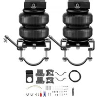
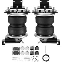
| Kit Contents | Frame brackets, spring brackets, wear pads, hardware, air line, valves, caps, manual |
| Maintenance | Check pressure weekly, clean with garden hose |
| Safety | Do not exceed 100 PSI, do not exceed GVWR, use soapy water for leaks |
| Warranty | Electronic warranty certificate at www.vevor.com/support |
| Country of Manufacture | China |
| Manual Available | Yes, in multiple languages (FR, DE, EN, IT, NL, PL, SV, etc.) |
| Mounting Type | On frame and axle |
| Recommended Leak Test | Soapy water solution |
Frequently Asked Questions - 7X 57289 Vevor
User questions about 7X 57289 Vevor
0 question about this device. Answer the ones you know or ask your own.
Ask a new question about this device
Download the instructions for your Air suspension kit in PDF format for free! Find your manual 7X 57289 - Vevor and take your electronic device back in hand. On this page are published all the documents necessary for the use of your device. 7X 57289 by Vevor.
USER MANUAL 7X 57289 Vevor
Technical Support and E-Warranty Certificate www.vevor.com/support
AIR BAG SUSPENSION KIT
MODEL: 7X 57289
We continue to be committed to provide you tools with competitive price. "Save Half", "Half Price" or any other similar expressions used by us only rep estimate of savings you might benefit from buying certain tools with us compared top brands and does not necessarily mean to cover all categories of tools offer are kindly reminded to verify carefully when you are placing an order with us actually saving half in comparison with the top major brands.
VEVOR®
TOUGH TOOLS, HALF PRICE
AIR BAG SUSPENSION KI
MODEL: 7X 57289

natural_image
Mechanical testing apparatus with black and metallic components mounted on a black base (no visible text or symbols)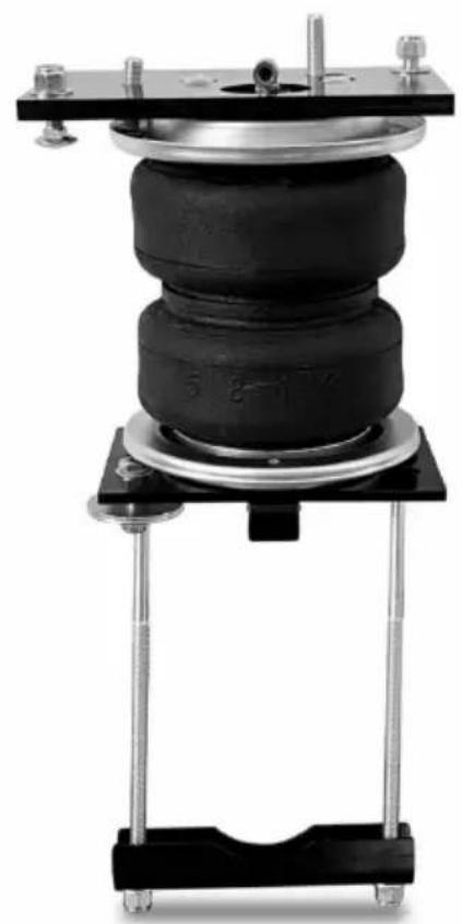
natural_image
Mechanical testing apparatus with black and metallic components mounted on a black base (no visible text or symbols)NEED HELP? CONTACT US!
Have product questions? Need technical support? Please feel fr contact us:
Technical Support and E-Warranty Certificate www.vevor.com/support
This is the original instruction, please read all manual instruction carefully before operating. VEVOR reserves a clear interpretation user manual. The appearance of the product shall be subject to product you received. Please forgive us that we won't inform you there are any technology or software updates on our product.
Thank you for purchasing the 7X 57538 Kit! Please kindly be advised to rea instructions carefully before installing the air spring kit.
Please take safety precautions accordingly during installation.
The installation instructions are based on the left side or based on the driver of the vehicle, and the structure on the right side can refer to the same mode the left side.
The retrofit kit you purchased is a single valve inflation system.
Please note that the air spring will bend and expand under working conditions. Ensure there is enough space for it to work properly and avoid friction between air spring and other chassis parts.
IMPORTANT SAFETY NOTICE
The installation of this kit does not alter the gross vehicle weight rating (GV) payload of the vehicle. Check the vehicle's owner's manual and do not exceed maximum load listed for this vehicle.
Gross vehicle weight rating: The maximum allowable weight of the fully load vehicle (including passengers and cargo). This number — along with other well limits, as well as tire, rim size and inflation pressure data — is shown on the vehicle's Safety Compliance Certification Label.
Payload: The combined, maximum allowable weight of cargo and passengers the truck is designed to carry. Payload is GVWR minus the base curb weigh
Hazard notations appear in various locations in this publication. Information which is highlighted by one of these notations must be observed to help minimize personal injury or possible improper installation which may render the vehicle unsafe. Notes are used to help emphasize areas of procedural importance and
provide helpful suggestions. The following definitions explain the use of these notations as they appear throughout this guide.

INDICATES IMMEDIATE HAZARDS WHICH WILL RESULT IN SEVERE PERSONAL INJURY OR DEATH.

INDICATES HAZARDS OR UNSAFE PRACTICES WHICH COULD RESULT IN SEVERE PERSONAL INJURY OR DEATH.

INDICATES HAZARDS OR UNSAFE PRACTICES WHICH COULD RESULT IN DAMAGE TO THE MACHINE OR MINOR PERSONAL INJURY.
PARAMETER LIST
| Model | standard |
| Adapted models | 2014-2023 Dodge Ram 2500 2WD&4WD |
| rated load (lbs) | 5000 |
| Use the pressure (psi) | 5-100 |
PARTS LIST
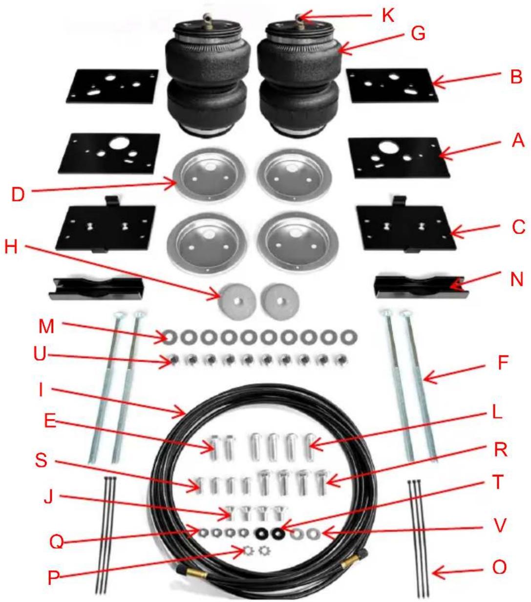
| ITEM | DESCRIPTION | QTY | ITEM | DESCRIPTION | QTY |
| A | Upper frame bracket | 2 | L | 3/8"-24 x 7/8" Button-head screw | 4 |
| B | Upper air spring bracket | 2 | M | 3/8" Flat washer | 10 |
| C | Lower bracket | 2 | N | Clamp bar | 2 |
| D | Roll plate (silver zin plated) | 4 | O | Zip tie | 6 |
| E | 3/8"-16 x 1.25" Hex-head bolt | 2 | P | Star washer | 2 |
| F | 3/8"-16 x 10" Carriage bolt | 4 | Q | 5/16" Hex nut | 4 |
| G | Air spring | 2 | R | 3/8"-16 x 1.25" Carriage bolt | 4 |
| H | Large flat washer | 2 | S | M10-1.5 Button-head screw | 4 |
| I | Nylon air line | 1 | T | Rubber washer | 2 |
| J | 3/8"-24 x 3/4" Flat-head screw | 4 | U | 3/8"-16 Nylon lock nut | 10 |
| K | Push-to-connect (PTC) fitting | 2 | V | M8 Flat washer | 2 |
* not pictured in the Installation Diagram
| DESCRIPTION | QTY |
| Valve cap | 2 |
| instruction | 1 |
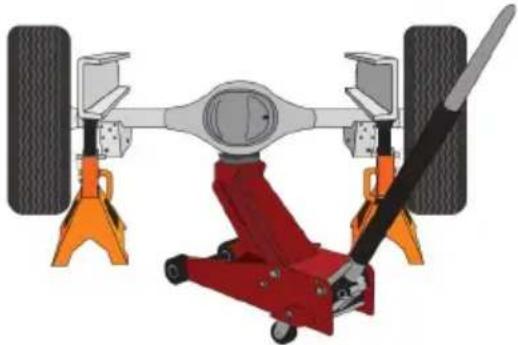
GETTING STARTED
- Raise the vehicle and support the frame with jack stands, drop the axle make room for the air spring assemblies to be put into position between the and axle (Fig. 2).
natural_image
Mechanical assembly diagram showing a red and orange lift with attached components, no text or symbols present.fig. 2
- On the left (driver's) side axle there is a small vent tube (Fig. 3) that not tied on an angle with a zip tie (BB).
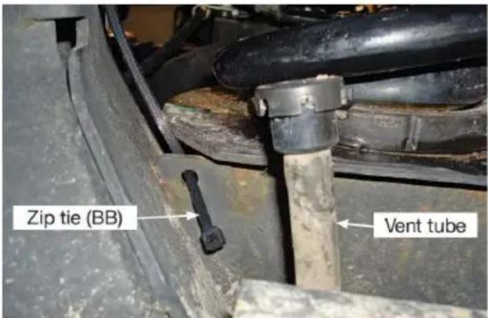
fig. 3
- Insert the zip tie into the small hole in the lower coil spring seat, then a vent tube and just snug the zip tie enough to angle the tube out of the wa
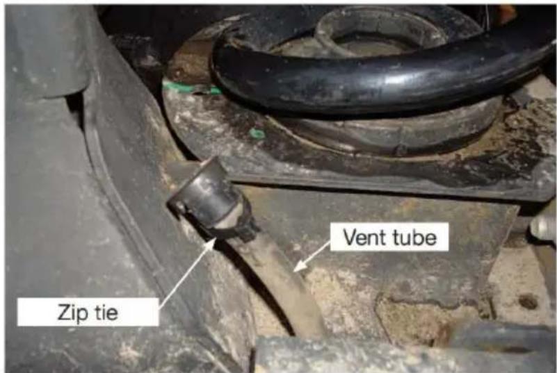
fig. 4
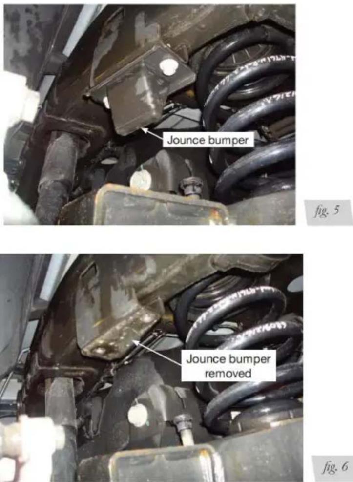
- Remove the left and right side jounce bumpers (Figs. 5 & 6) 6).
- Attach the upper frame bracket (A) to the frame (Figs. 7 & 8) using the button head screws (S).
NOTE: The large hole in the bracket goes to the outside of the frame (towa tire).
Driver's side
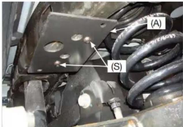
fig. 7
Passenger's side
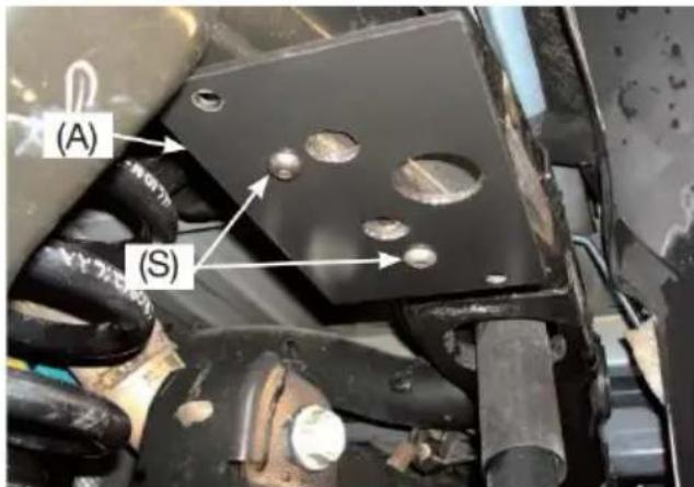
fig. 8
6.Torque the mounting hardware to 30 lb.-ft. (41Nm).
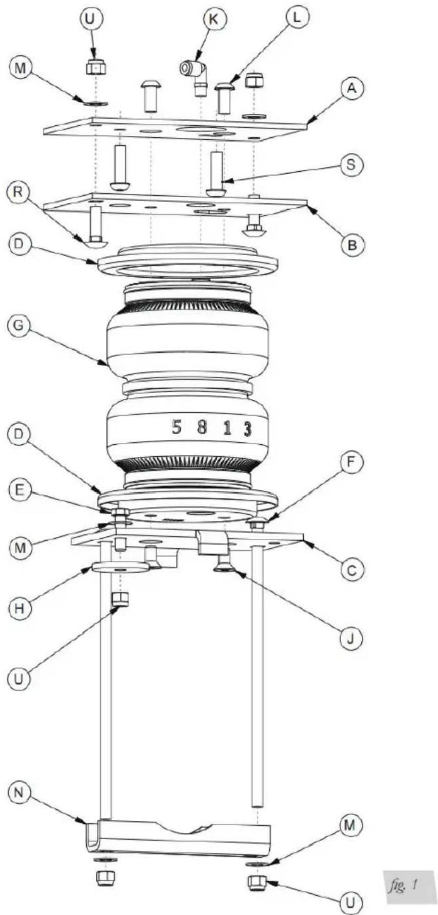
BUILDING THE AIR SPRING ASSEMBLIES
- Set a roll plate (D) over the top of each air spring (G).
NOTE: The radiused (rounded) edge of the roll plate (D) will be toward the spring so that the air spring is seated inside both roll plates.
- Install the swivel fitting (K) into the top of the air spring finger tight plus a half turns (Fig. 9). Repeat for both air springs. It is recommended that the nozzle (K) be wrapped with PTFE TAPE during assembly.
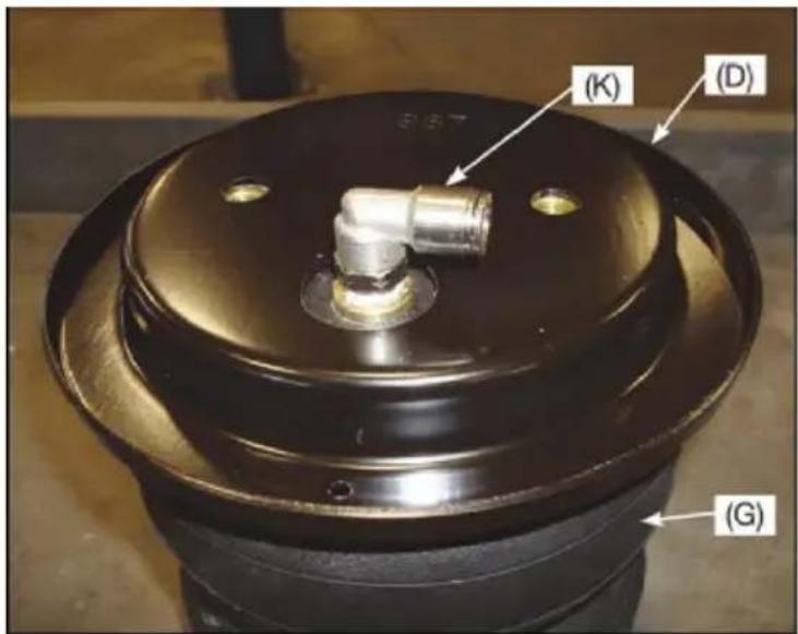
fig. 9
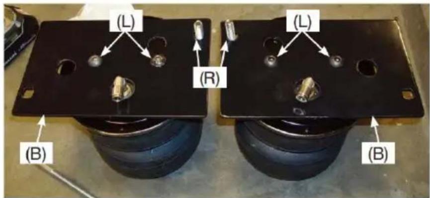
- Set both air springs in front of you with the fittings pointing at you (Fig. 4. Insert the 3/8" carriage bolt (R) through the upper air spring bracket (B) hole at the back side only (Figs. 1 & 10).
NOTE: The upper air spring brackets will be a mirror image when set onto springs (see Fig. 10).
Left (driver's) side assembly
Right (passenger's) side assembly
fig. 10
- Set both brackets onto the air springs and attach using the 3/8" button h screws (L). Torque no more than 20 lb.-ft. (27Nm).
- Install the thick 3/8" flat washer (H) onto the lower bracket (C) with 3/8" hex-head bolt (E), 3/8" flat washer (M) and 3/8" nylon lock nut (U) as show 1 & 11). Tighten securely.
- Insert the long 3/8" carriage bolts (F) into the square holes in the lower (Figs. 1 & 11).
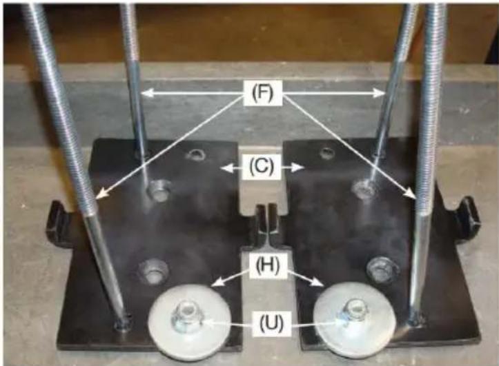
fig. 11
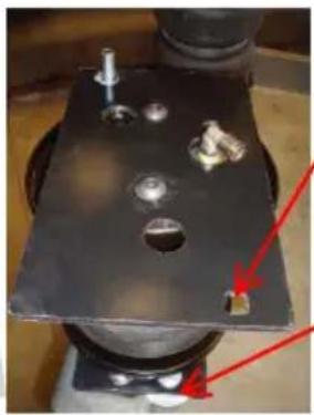
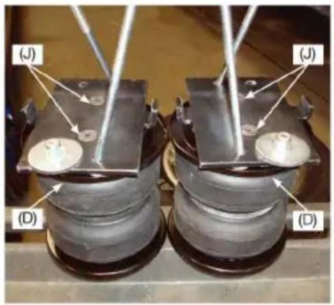
- Set a roll plate (D) over the bottom of the air spring and install the low onto the air spring assembly so that the large washer previously installed will forward of the axle once installed (Figs. 12 & 13) using the 3/8" flat head : (J). Torque to no more than 20 lb-ft. (27Nm).
Left (driver's) side assembly
natural_image
Close-up of a metallic mechanical component with holes and a red arrow pointing to a small square feature (no text or symbols visible)Make sure the lower bracket attached with the large wasl is on the same side as the open square hole in the top bracket as shown.
The large washer installed on the lower bracket will be forward of the axle once installed.
Left (driver's) side assembly
Right (passenger's) side assembly
See Figures 8 & 10 to position correctly on the Assembly.
fig. 13
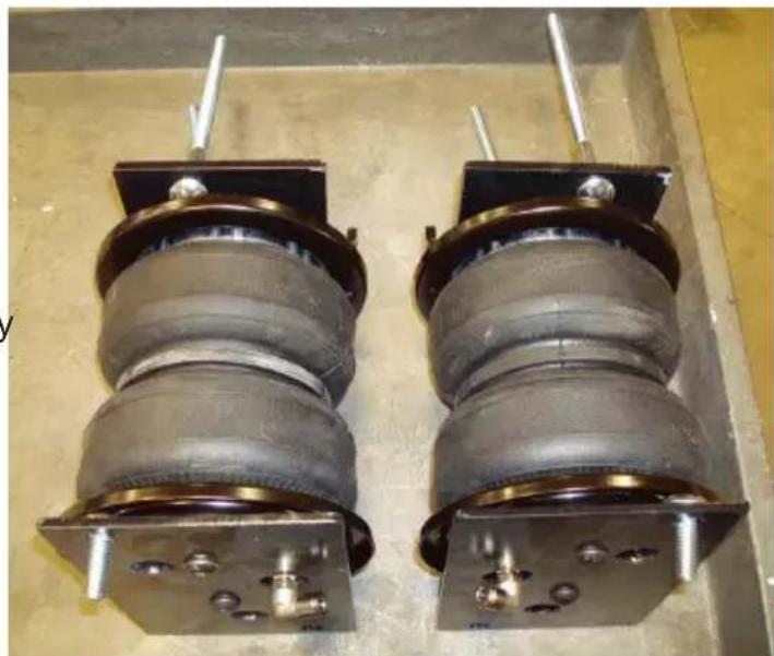
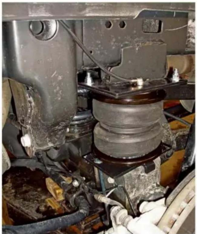
FINISHED ASSEMBLIES
Left (driver's) side assembly
natural_image
Two cylindrical mechanical components mounted on a metal frame, no visible text or symbolsRight (passenger's) side assembly
fig. 14
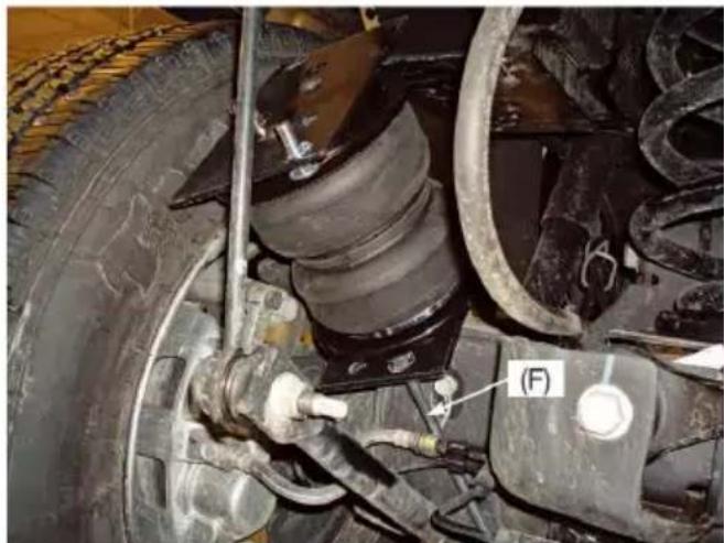
ATTACHING THE ASSEMBLIES TO THE FRAME
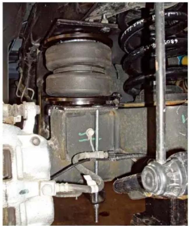
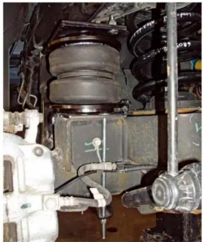
- With the axle slightly hanging, set the left (driver's) side assembly on the making sure that the carriage bolt (F) goes in between the brake line and t
(Fig. 15).
natural_image
Close-up of a vehicle's lower suspension system with visible tire, springs, and brake components (no text or symbols)fig. 15
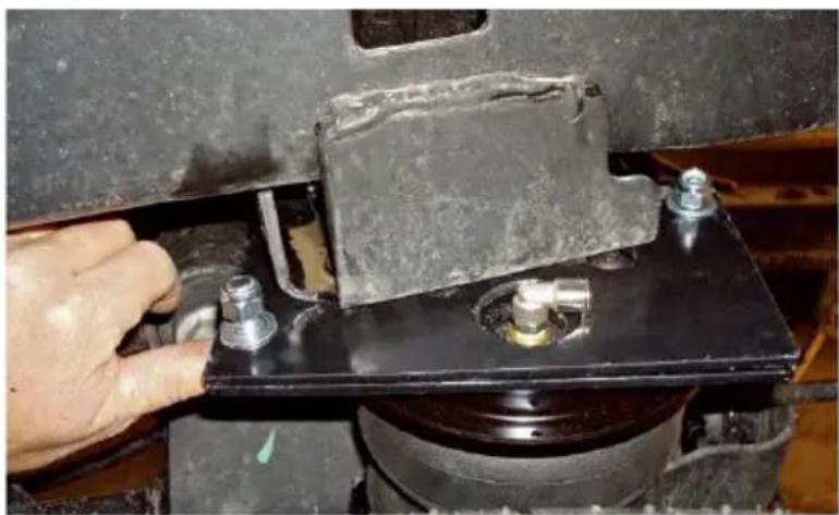
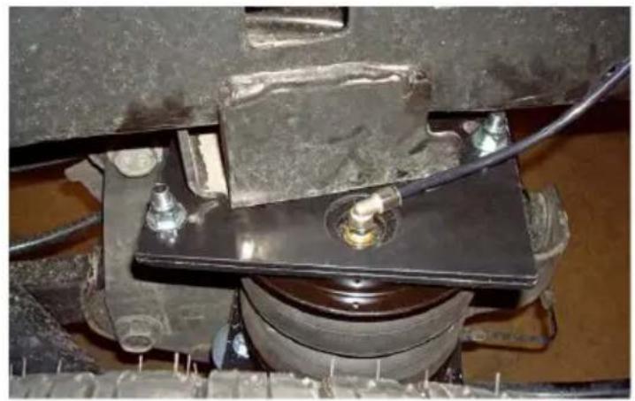
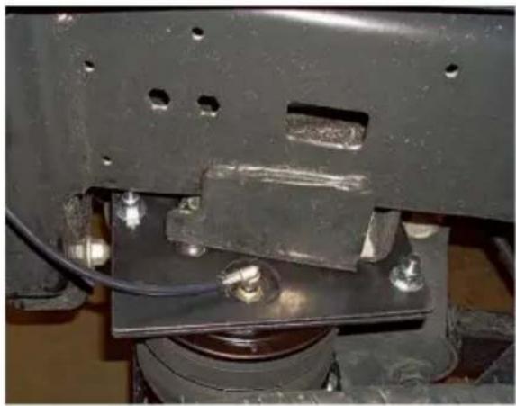
- Carefully set the upper air spring bracket into position, making sure that t carriage bolt and fitting line up with the holes in the frame bracket (Fig. 16) the axle up so that the brackets come together making sure the fitting and carriage bolt go through the holes and do not bind.
natural_image
Close-up of a hand adjusting a metal bracket component on a black metal plate (no visible text or symbols)fig. 16
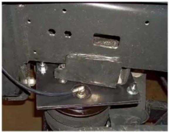
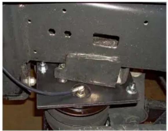
- Insert the remaining carriage bolt (R) through the open front holes from the bottom up and cap both upper carriage bolts with 3/8" flat washer (M) and nylon lock nut (U). Torque to 16 lb.-ft. (22Nm). Repeat for the other side.
NOTE: It may be necessary to use a 9/16" crows foot adapter to torque the underneath the frame.
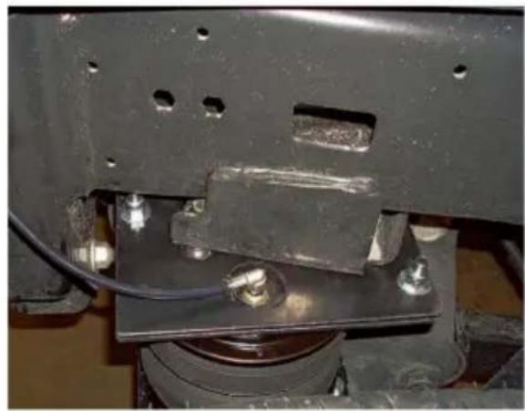
- Bring the axle all the way up and position the lower bracket over the low jounce bumper strike plate. The large washer on the bottom of the bracket is be positioned forward and over the lower jounce bumper strike plate (Fig. 17)
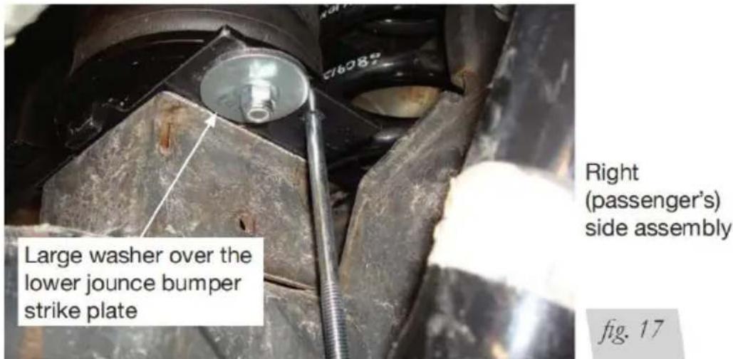
- Set the clamp bar (N) over the two long carriage bolts (F) under the axl cap with two 3/8" flat washers (M) and 3/8" nylon lock nuts (U) (Fig. 18).
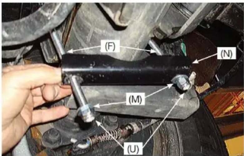
fig. 18
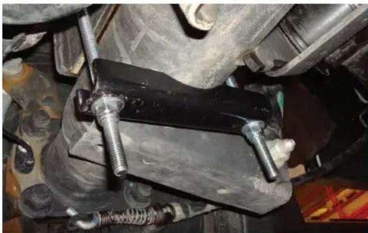
- Torque evenly to 10 lb.-ft. (14Nm) (Fig. 19). Repeat for the other side.
natural_image
Close-up of a mechanical assembly with bolts and bolts mounted on a black metal bracket (no visible text or symbols)fig. 19
- Raise the axle or lower the vehicle and remove the jack stands.
INSTALLING THE AIR LINES
Air lines are routed from the air springs to Schrader valves. lines come in t styles: nylon and braided stainless steel. Air Begin by choosing locations for the Schrader valves and drill a 5/16" hole (8mm), if necessary (Fig. 20).
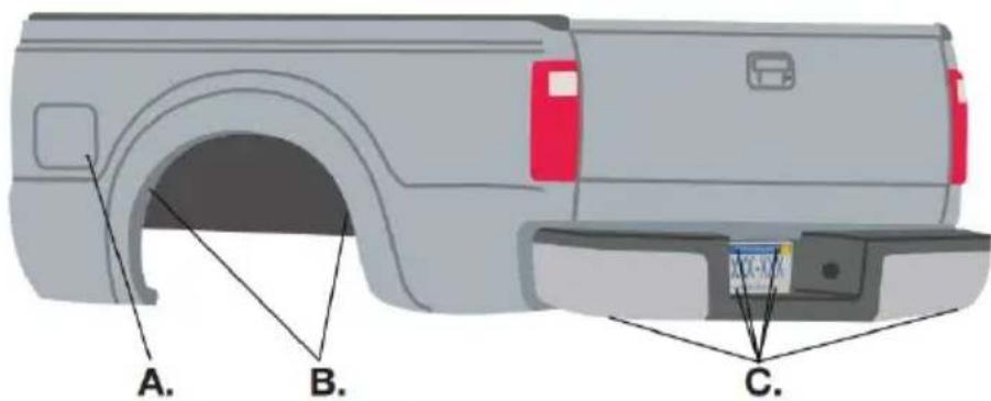
* For LoadLifter Ultimate Plus kits, the recommended location for the Schrader valves is the rear bumper area or license plate.
A. Inside fuel tank filler door
B. Inside rear wheel wells
C. License plate or rear bumper area*
fig. 20

CAUTION
KEEP AT LEAST 6" OF CLEARANCE BETWEEN ALL A LINES AND THE EXHAUST SYSTEM. AVOID SHARP BENDS AND EDGES.
INSTALLING NYLON AIR LINES
- Cut the air line in half. Make clean, square cuts with a razor blade or h (Fig. 21). Do not use scissors or wire cutters.
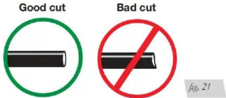
- Use zip ties to secure the airline to fixed points along the chassis. Do n or kink the air line. The minimum bend radius for the air line is 1" (25mm), least 2" (50mm) of slack in the air line to allow for any movement that mig the air line.
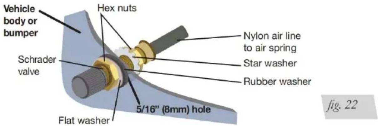
- Install the Schrader valve in the chosen location (Fig. 22).
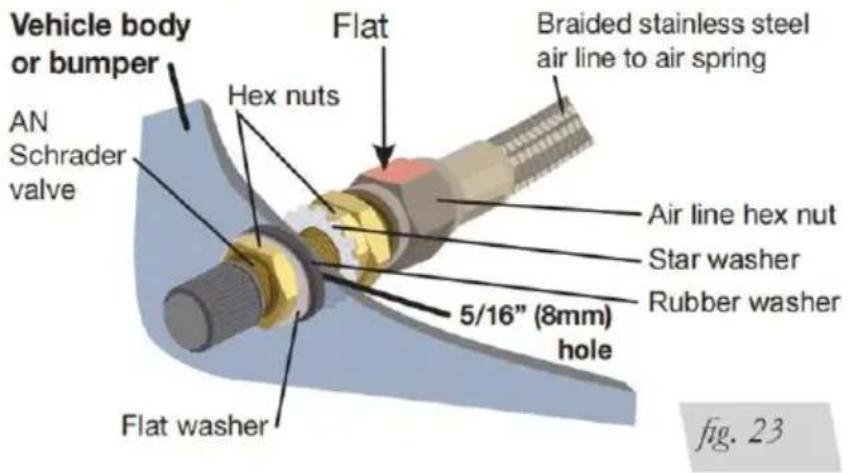
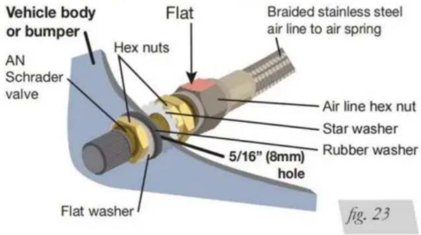
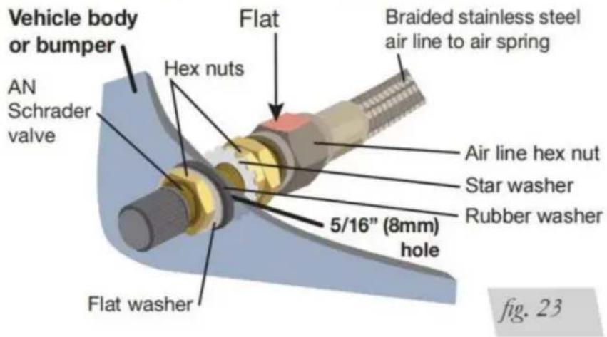
INSTALLING BRAIDED STAINLESS STEEL AIR LINES

CAUTION
KEEP THE AIR LINE AWAY FROM THE FUEL LINE, BRAK LINES AND ELECTRICAL WIRES.
- Use zip ties to secure t airline to fixed points along chassis every 6" to 8" (150-300mm). Leave at least (50mm) of slack to allow for any movement that might p on the air line.
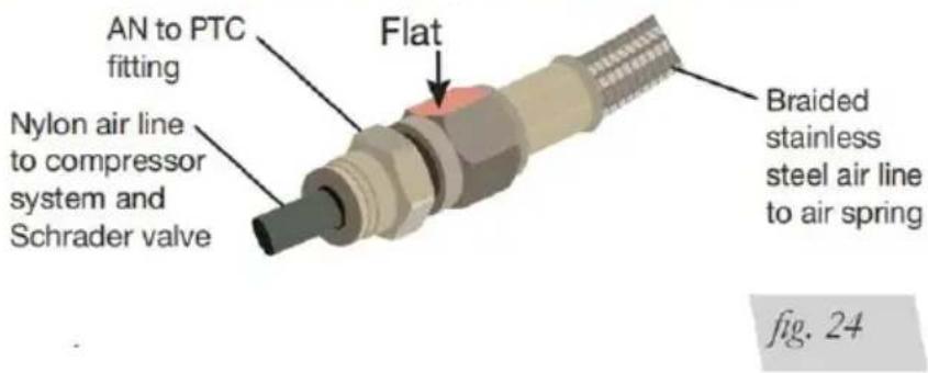
- Tighten the airline hex n finger tight, then use 2 wrenches to turn 1 additional flat (1/6 of one full turn). [ overtighten (Figs. 23 or 24). The easiest way to tighten fitting is off the vehicle. Ins the Schrader valve in the chosen location.
- Coil and secure any exc airline in an area where it not be susceptible to damage
The braided stainless steel airline cannot be trimmed.
Air Line Setup Without Compressor System
Air Line Setup for Compressor Integration
Finished Installation Photos
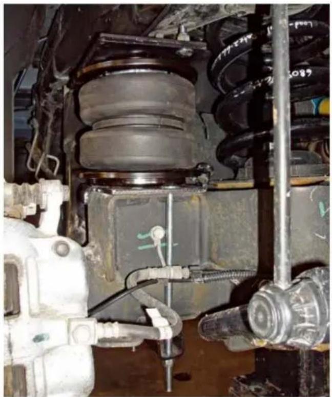
- The following images show the finished installation of both sides. (Figs. 25)
natural_image
Close-up of a mechanical assembly with a car tire and mounting bracket (no visible text or symbols)Left (driver's) side top view
natural_image
Close-up of a mechanical assembly with bolts and a metal frame (no visible text or symbols)Right (passenger's) side top view
fig. 26
natural_image
Close-up of a vehicle suspension system with visible mechanical components and wiring (no text or symbols)Left (driver's) side back view shown with tire removed
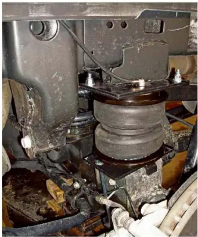
natural_image
Close-up of a car suspension system with visible mechanical components and wiring (no text or symbols)Right (passenger's) side view shown with tire removed
fig. 28
BEFORE OPERATING
CHECKING FOR LEAKS
- Inflate the air spring to 30 PSI (2BAR).
-
Spray all connections and the inflation valves with a solution of liquid dish soap as Spot leaks easily by looking for bubbles in the soapy water.
-
After the test, deflate the springs to the minimum pressure required to restore the to normal ride height. Do not deflate to lower than 5 PSI (.34BAR).
- Check the air pressure again after 24 hours. A 2-4 PSI (.14-.28BAR) loss after ir installation is normal. Retest for leaks if the loss is more than 5 PSI (.34BAR).
FIXING LEAKS
- If there is a problem with the swivel fitting:
a. Check the airline connection by deflating the spring and removing the line pulling the collar against the fitting and pulling firmly on the air line. Trim (25mm) off the end of the air line. Be sure the cut is clean and square 21). Reinsert the air line into the push-to-connect fitting. b. Check the threaded connection by tightening the swivel fitting another hat turn. If it still leaks, deflate the air spring, remove the fitting, and re-coat threads with thread sealant. Reinstall by hand tightening as much as possib and then use a wrench for an additional two turns.
- If there is a problem with the inflation valve:
a. Check the valve core by tightening it with a valve core tool. b. Check the air line by removing the air line from the barbed fitting. Cut airline off a few inches in front of the fitting and use a pair of pliers or to pull/ twist the airline off of the fitting.
DO NOT CUT OFF THE AIR LINE OFF AT THE FITTING BECAUSE THIS COULD NICK
THE BARB AND RENDER THE FITTING USELESS.
INSTALLATION CHECKLIST
Clearance test — Inflate the air springs to 75-90 PSI (5.2-6.2BAR) and make there is at least 1/2" (13mm) clearance from anything that might rub against sleeve. Be sure to check the tire, brakes, frame, shock absorbers and brake cables.
Leak test before road test — Inflate the air springs to 75-90 PSI (5.2-6.2B and check all connections for leaks. All leaks must be eliminated before the is road tested.
Heat test — Be sure there is sufficient clearance from heat sources, at least air springs and air lines. If a heat shield was included in the kit, install it.
Fastener test — Recheck all bolts for proper torque.
Road test — The vehicle should be road tested after the preceding tests. In the springs to recommended driving pressures. Drive the vehicle 10 miles (16 and recheck for clearance, loose fasteners and air leaks.
Operating instructions — If professionally installed, the installer should review the operating instructions with the owner. Be sure to provide the owner with the paperwork that came with the kit.
POST-INSTALLATION CHECKLIST
Overnight leak down test — Recheck air pressure after the vehicle has been used for 24 hours. If the pressure has dropped more than 5 PSI (.34BAR), there is a leak that must be fixed. Either fix the leak yourself or return to installer for service.
Air pressure requirements — It is important to understand the air pressure requirements of the air spring system. Regardless of load, the air pressure shall always be adjusted to maintain adequate ride height at all times while driving Thirty-day or 500-mile (800km) test —Recheck the air spring system after 3 days or 500 miles (800km), whichever comes first. If any part shows signs of rubbing or abrasion, the source should be identified and moved, if possible. If not possible to relocate the cause of the abrasion, the air spring may need remounted. If professionally installed, the installer should be consulted. Check fasteners for tightness
PRODUCT USE, MAINTENANCE AND SERVICING
Minimum Recommended Pressure
5 PSI (.34BAR)
Maximum Air Pressure
100 PSI (7BAR)
MAINTENANCE GUIDELINES
NOTE: By following the steps below, vehicle owners will obtain the longest life and best results from their air springs.
-
Check air pressure weekly.
-
Always maintain normal ride height. Never inflate beyond 100 PSI (7BAR).
- If the system develops an air leak, use a soapy water solution to check line connections and the inflation valve core before deflating and removing the spring.

CAUTION
FOR SAFETY AND TO PREVENT POSSIBLE DAMAGE TO THE VEHICLE, DO NOT EXCEED MAXIMUM GROSS
VEHICLE WEIGHT RATING (GVWR), AS INDICATED BY THE VEHICLE MANUFACTURER. ALTHOUGH THE AIR SPRINGS ARE RATED AT A MAXIMUM INFLATION PRESSURE OF 100 PSI (7BAR), THE AIR PRESSURE ACTUALLY NEEDED IS DEPENDENT ON LOAD AND GROSS VEHICLE WEIGHT RATING.
- Loaded vehicles require at least 25 PSI (1.7BAR). A “loaded vehicle” refer vehicle with a heavy bed load, a trailer or both. Never exceed GVWR, regard of air spring, air pressure or another load assist. The springs in this kit will approximately 40 pounds (18kg) of load (combined on both springs) for each (.07BAR) of pressure. The required air pressure will vary depending on the s the original suspension. Operating the vehicle below the minimum air spring pressure will void the warranty.
- When increasing load, always adjust air pressure to maintain normal ride I Increase or decrease pressure from the system as necessary to attain normal height for optimal ride and handling. Remember that loads carried behind the (including tongue loads) require more leveling force (pressure) than those carri directly over the axle.
- Always add air to springs in small quantities, checking the pressure frequency
- Should it be necessary to raise the vehicle by the frame, make sure the is at minimum pressure (5 PSI [.34BAR]) to reduce the tension on the sus brake components. Use of on-board leveling systems do not require deflation disconnection.
- Periodically check the air spring system fasteners for tightness. Also, check air springs for any signs of rubbing. Realign if necessary.
- On occasion, give the air springs a hard spray with a garden hose to re mud, sand, gravel or other debris.
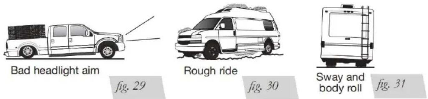
TUNING THE AIR PRESSURE
Pressure determination comes down to three things — level vehicle, ride com and stability.
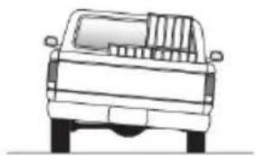
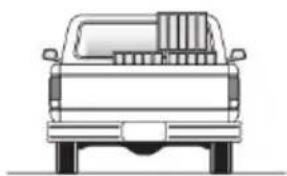
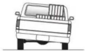
1. Level vehicle
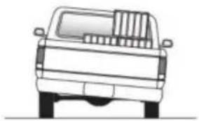
If the vehicle's headlights are shining into the trees or the vehicle is leaning side, then it is not level (Fig. 29). Raise the air pressure to correct either c problems and level the vehicle.
2. Ride comfort
If the vehicle has a rough or harsh ride it may be due to either too much or not enough (Fig. 30). Try different pressures to determine the best ride cost
3. Stability
Stability translates into safety and should be the priority, meaning the driver need to sacrifice a perfectly level and comfortable ride. Stability issues include control, bounce, dive during braking and sponginess (Fig. 31). Tuning out these problems usually requires an increase in pressure.
GUIDELINES FOR ADDING AIR
- Start with the vehicle level or slightly above.
- When in doubt, always add air.
- If the front of the vehicle dives while braking, increase the pressure in the air bags, if equipped.
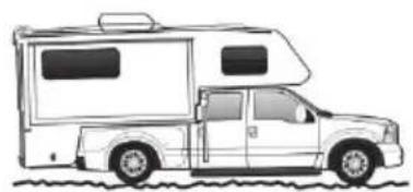
-
If it is ever suspected that the air bags have bottomed out, increase the (Fig. 32).
-
Adjust the pressure up and down to find the best ride.
-
If the vehicle rocks and rolls, adjust the air pressure to reduce movement
-
It may be necessary to maintain different pressures on each side of the Loads such as water, fuel, and appliances will cause the vehicle to be heavy one side (Fig. 33). As much as a 50 PSI (3.5BAR) difference is not uncommon
natural_image
Side view line drawing of a vintage-style camper van (no text or symbols)Bottoming out
natural_image
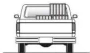
Front view line drawing of a pickup truck (no text or symbols)Unlevel
natural_image
Front view of a pickup truck viewed from the side (no text or symbols)Level
fig. 33
fig. 32
Troubleshooting Guide
| PROBLEM | CAUSE | SOLUTION |
| System won't maintain pressure overnight. | Improperly installed airline, air line has holes or crac | Leak test the air line connecti the threaded connection into th air spring, and all fittings in t control system. |
| Air spring or airline leak. | Fitting seal or airline is compromised. | Check to make sure air lines seated in connectors. Inspect fittings with soapy water. Trim hose or re-seal fitting. Ensure lines are cut straight. |
| Corner won't raise o air leak develops. | Look for a kink or fold air line. | Replace any airline that has b kinked. |
FREQUENTLY ASKED QUESTIONS
Q. Will installing air springs increase the weight ratings of a vehicle?
No. Adding air springs will not change the weight ratings (GAWR, GCWR and or GVWR) of a vehicle. Exceeding the GVWR is dangerous and voids the warranty.
Q. Is it necessary to keep air in the air springs at all times and how pressure will they need?
The recommended minimum air pressure is 5 PSI (.34BAR), Ultimate and Ulti Plus, can safely be run at zero air pressure unladen (no load).
Q. Is it necessary to add a compressor system to the air springs?
No. Air pressure can be adjusted with any type of compressor as long as it produce sufficient pressure to service the springs. Even a bicycle tire pump is used, but it's a lot of work.
Q. How long should air springs last?
If the air springs are properly installed and maintained they can last indefinite
Q. Will raising the vehicle on a hoist for service work damage the air springs?
No. The vehicle can be lifted on a hoist for short-term service work such as rotation or oil changes. However, if the vehicle will be on the hoist for a proper period of time, support the axle with jack stands in order to take the tension the air springs.
Manufacturer: Shanghaimuxinmuyeyouxiangongsi
Address: Shuangchenglu 803nong11hao1602A-1609shi, baoshanqu, shanghai 200000 CN.
Imported to AUS: SIHAO PTY LTD. 1 ROKEVA STREETEASTWOOD NSW 2122 Australia
Imported to USA: Sanven Technology Ltd. Suite 250, 9166 Anaheim Place, Rancho Cucamonga, CA 91730
| UK | REP |
YH CONSULTING LIMITED.
C/O YH Consulting Limited Office 147,
Centurion House, London Road,
Staines-upon-Thames, Surrey, TW18 4AX
| EC | REP |
E-CrossStu GmbH
Mainzer Landstr.69,
60329 Frankfurt am Main.
VEVOR®
TOUGH TOOLS, HALF PRICE
Technical Support and E-Warranty Certificate
www.vevor.com/support
VEVOR®
TOUGH TOOLS, HALF PRICE
natural_image
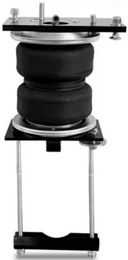
Mechanical testing device with black and metallic components mounted on a stand (no visible text or symbols)
natural_image
Mechanical testing device with black and metallic components mounted on a black base (no visible text or symbols)BESOIN D'AIDE? CONTACTEZ-NOUS!
fig. 1
COMMENCER
natural_image
Mechanical assembly diagram showing a vehicle chassis with two large tires and a red support structure (no text or symbols)fig. 2
fig. 4
fig. 11
FIXATION DES ASSEMBLAGES AU CADRE
natural_image
Close-up of a vehicle's lower suspension system with visible tire, car chassis, and mechanical components (no text or symbols)fig. 15
natural_image
Close-up of a hand adjusting a mechanical component with bolts and a metal bracket (no visible text or symbols)fig. 16
natural_image
Close-up of a mechanical assembly with bolts and components, no visible text or symbols* For LoadLifter Ultimate Plus kits, the recommended location for the Schrader valves is the rear bumper area or license plate.
A. Inside fuel tank filler door
B. Inside rear wheel wells
C. License plate or rear bumper area*
fig. 20

CAUTION
GARDER AU MOINS 6" DE DÉGAGEMENT ENTRE TOUT L'AIR CONDUITES ET SYSTÈME D'ÉCHAPPEMENT. ÉVITER LES POINTS COUDES ET BORDS.
INSTALLATION DE CONDUITES AÉRIENNES EN NYLON
fig. 22
INSTALLATION DE CONDUITES D'AIR TRESSÉES EN ACIER INOXYDABLE

CAUTION
GARDER LA CONDUITE D'AIR ÉLOIGNÉE DE LA CONDUITE DE CARBURANT, FREIN LIGNES ET FILS ÉLECTRIQUES.
Air Line Setup Without Compressor System
Air Line Setup for Compressor Integration

fig. 24
natural_image
Close-up of a vehicle suspension system with brake and wheel assembly (no visible text or symbols)Left (driver's) side top view

natural_image
Close-up of a vehicle chassis frame with bolts and wiring (no visible text or symbols)Right (passenger's) side top view
fig. 26
natural_image
Close-up of a vehicle suspension system with car chassis and mechanical components (no visible text or symbols)Left (driver's) side back view shown with tire removed

natural_image
Close-up of a car suspension system with visible springs and wiring (no text or symbols)Right (passenger's) side view shown with tire removed
fig. 28
AVANT L'UTILISATION
VÉRIFICATION DES FUITES
NE COUPEZ PAS LA CONDUITE D'AIR AU RACCORD CAR CELA
POURRAIT NICK
LE BARBEAU ET REND LE RACCORD INUTILE.
LISTE DE CONTRÔLE D'INSTALLATION
Minimum Recommended Pressure
5 PSI (.34BAR)
Maximum Air Pressure
100 PSI (7BAR)
DIRECTIVES D'ENTRETIEN
natural_image
Side profile illustration of a car with a large vehicle (no text or symbols)Bottoming out

natural_image
Front view line drawing of a pickup truck (no text or symbols)Unlevel

natural_image
Front view line drawing of a pickup truck (no text or symbols)Level
fig. 33
Lieu, Rancho Cucamonga, CA 91730
YH CONSULTING LIMITÉE.
C/O YH Consulting Limited Bureau 147,
Centurion House, London Road,
Staines-upon-Thames, Surrey, TW18 4AX
E-CrossStu GmbH
Mainzer Landstr.69,
natural_image
Mechanical testing device with black and metallic components mounted on a stand (no visible text or symbols)
natural_image
Mechanical testing device with black and metallic components mounted on a black base (no visible text or symbols)fig. 1
ERSTE SCHRITTE
natural_image
Mechanical assembly diagram showing a vehicle chassis with two large tires and a red support structure (no text or symbols)fig. 2
fig. 4
Machine Translated by Google
fig. 11
natural_image
Close-up of a vehicle's lower suspension system with visible tire, car chassis, and mechanical components (no text or symbols)fig. 15
natural_image
Close-up of a hand adjusting a mechanical component with bolts and a metal bracket (no visible text or symbols)fig. 16
natural_image
Close-up of a mechanical assembly with bolts and a black bracket (no visible text or symbols)* For LoadLifter Ultimate Plus kits, the recommended location for the Schrader valves is the rear bumper area or license plate.
A. Inside fuel
tank filler
door
B. Inside rear wheel wells
C. License plate or rear bumper area*
fig. 20

CAUTION
fig. 22
Air Line Setup Without Compressor System

Air Line Setup for Compressor Integration

fig. 24
natural_image
Close-up of a vehicle suspension system with brake and wheel assembly (no visible text or symbols)Left (driver's) side top view
natural_image
Close-up of a vehicle chassis frame with bolts and wiring (no visible text or symbols)Right (passenger's) side top view
fig. 26

natural_image
Close-up of a car suspension system with visible mechanical components and wiring (no text or symbols)Left (driver's) side back view shown with tire removed

natural_image
Close-up of a car suspension system with visible springs and wiring (no text or symbols)Right (passenger's) side view shown with tire removed
fig. 28
VOR DEM BETRIEB
AUF LECKS PRÜFEN
Minimum Recommended Pressure
5 PSI (.34BAR)
Maximum Air Pressure
100 PSI (7BAR)
WARTUNGSRICHTLINIEN
natural_image
Side profile illustration of a car with a large RV (no text or symbols)Bottoming out

natural_image
Front view line drawing of a pickup truck (no text or symbols)Unlevel
natural_image
Front view line drawing of a pickup truck (no text or symbols)Level
fig. 33
C/O YH Consulting Limited Office 147,
Centurion House, London Road,
Staines-upon-Thames, Surrey, TW18 4AX
www.vevor.com/support
VEVOR®
TOUGH TOOLS, HALF PRICE
KIT SOSPENSIONI AIRBAG
MODELLO: 7X 57289
KIT SOSPENSIONI AIRBAG
MODELLO: 7X 57289
natural_image
Mechanical testing device with black and metallic components mounted on a stand (no visible text or symbols)
natural_image
Mechanical testing device with black and metallic components mounted on a black base (no visible text or symbols)HO BISOGNO DI AIUTO? CONTATTACI!
fig. 1
INIZIARE
natural_image
Mechanical assembly diagram showing a red lift platform with two large tires and a central hub, no text or symbols present.fig. 2
fig. 4
- Rimuovere i respingenti laterali sinistro e destro (Fig. 5 e 6ÿ6).
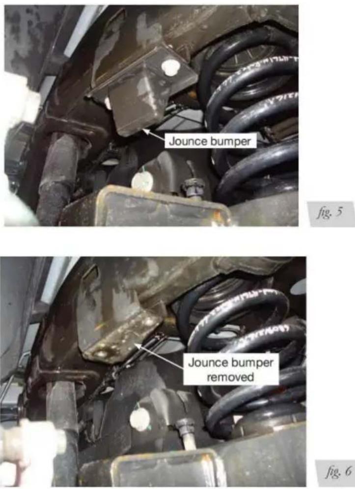
fig. 11
natural_image
Close-up of a vehicle's lower suspension system with visible tire, car chassis, and mechanical components (no text or symbols)fig. 15
natural_image
Close-up of a hand adjusting a metal bracket component on a mechanical assembly (no visible text or symbols)fig. 16
natural_image
Close-up of a mechanical assembly with bolts and a black bracket (no visible text or symbols)* For LoadLifter Ultimate Plus kits, the recommended location for the Schrader valves is the rear bumper area or license plate.
A. Inside fuel tank filler door
B. Inside rear wheel wells
C. License plate or rear bumper area*
fig. 20

CAUTION
MANTENERE ALMENO 6" DI SPAZIO TRA TUTTA L'ARIA
LINEE E SISTEMA DI SCARICO. EVITARE TAGLIENTI
PIEGHE E BORDI.
fig. 22
INSTALLAZIONE DI LINEE ARIA IN TRECCIA DI ACCIAIO INOSSIDABILE

CAUTION
Air Line Setup Without Compressor System
Air Line Setup for Compressor Integration

fig. 24
natural_image
Close-up of a mechanical assembly with a car tire, clamping components, and wiring (no visible text or symbols)Left (driver's) side top view
natural_image
Close-up of a vehicle chassis frame with mounting hardware and bolts (no visible text or symbols)Right (passenger's) side top view
fig. 26
natural_image
Close-up of a vehicle suspension system with visible mechanical components and wiring (no text or symbols)Left (driver's) side back view shown with tire removed

natural_image
Close-up of a car suspension system with visible springs and wiring (no text or symbols)Right (passenger's) side view shown with tire removed
fig. 28
PRIMA DI OPERARE
CONTROLLO PERDITE
Minimum Recommended Pressure
5 PSI (.34BAR)
Maximum Air Pressure
100 PSI (7BAR)
natural_image
Side profile illustration of a car with a large RV (no text or symbols)Bottoming out
natural_image
Front view line drawing of a pickup truck (no text or symbols)Unlevel

natural_image
Front view line drawing of a pickup truck (no text or symbols)Level
fig. 33
Importato in AUS: SIHAO PTY LTD. 1 ROKEVA STREETEASTWOOD NSW 2122 Australia
C/O YH Consulting Limited Office 147,
Centurion House, London Road,
Staines-upon-Thames, Surrey, TW18 4AX

E-CrossStu GmbH
Mainzer Landstr.69,
elettronica www.vevor.com/support
VEVOR®
TOUGH TOOLS, HALF PRICE
natural_image
Mechanical testing device with black and metallic components mounted on a stand (no visible text or symbols)
natural_image
Mechanical testing device with black and metallic components mounted on a black base (no visible text or symbols)fig. 1
EMPEZANDO
natural_image
Mechanical assembly diagram showing a vehicle chassis with two large tires and a red support structure (no text or symbols)fig. 2
fig. 4
fig. 11
natural_image
Close-up of a vehicle's lower suspension system with visible tire, car chassis, and valve (no text or symbols)fig. 15
natural_image
Close-up of a hand adjusting a mechanical component with bolts and a metal bracket (no visible text or symbols)fig. 16
natural_image
Close-up of a mechanical assembly with bolts and a black bracket (no visible text or symbols)* For LoadLifter Ultimate Plus kits, the recommended location for the Schrader valves is the rear bumper area or license plate.
A. Inside fuel tank filler door
B. Inside rear wheel wells
C. License plate or rear bumper area*
fig. 20

CAUTION
MANTENGA AL MENOS 6" DE ESPACIO ENTRE TODO EL AIRE LÍNEAS Y SISTEMA DE ESCAPE. EVITE AFILADOS CURVAS Y BORDES.
Air Line Setup Without Compressor System

Air Line Setup for Compressor Integration
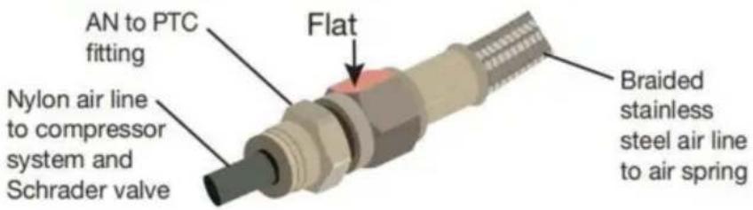
fig. 24
natural_image
Close-up of a vehicle suspension system with brake and wheel assembly (no visible text or symbols)Left (driver's) side top view

natural_image
Close-up of a vehicle chassis frame with bolts and wiring (no visible text or symbols)Right (passenger's) side top view
fig. 26

natural_image
Close-up of a vehicle suspension system with car chassis and mechanical components (no visible text or symbols)Left (driver's) side back view shown with tire removed

natural_image
Close-up of a car suspension system with visible springs and wiring (no text or symbols)Right (passenger's) side view shown with tire removed
fig. 28
ANTES DE OPERAR
COMPROBAR FUGAS
Minimum Recommended Pressure
5 PSI (.34BAR)
Maximum Air Pressure
100 PSI (7BAR)
natural_image
Side profile illustration of a car with a large RV (no text or symbols)Bottoming out

natural_image
Front view line drawing of a pickup truck (no text or symbols)Unlevel

natural_image
Front view line drawing of a pickup truck (no text or symbols)Level
fig. 33
fig. 32
Guía para resolver problemas
Centurion House, London Road,
Staines-upon-Thames, Surrey, TW18 4AX
E-CrossStu GmbH
Mainzer Landstr.69,
natural_image
Mechanical testing device with black and metallic components mounted on a stand (no visible text or symbols)
natural_image
Mechanical testing device with black and metallic components mounted on a black base (no visible text or symbols)POTRZEBUJE POMOCY? SKONTAKTUJ SIĘ Z NAMI!
fig. 1
ROZPOCZĘCIE
natural_image
Mechanical assembly diagram showing a red lift platform with two large tires and a central hub, no text or symbols present.fig. 2
fig. 4
Machine Translated by Google
fig. 11
natural_image
Close-up of a vehicle's lower suspension system with visible tire, car chassis, and valve (no text or symbols)fig. 15
natural_image
Close-up of a hand adjusting a mechanical component with bolts and a metal bracket (no visible text or symbols)fig. 16
natural_image
Close-up of a mechanical assembly with bolts and a black bracket (no visible text or symbols)* For LoadLifter Ultimate Plus kits, the recommended location for the Schrader valves is the rear bumper area or license plate.
A. Inside fuel tank filler door
B. Inside rear wheel wells
C. License plate or rear bumper area*
fig. 20

CAUTION
ZACHOWAJ CO NAJMNIEJ 6" ODSTĘPU MIĘDZY POWIETRZEM
PRZEWODY I UKŁAD WYDECHOWY. UNIKAJ OSTRA
ZGIĘCIA I KRAWĘDZIE.
fig. 22
MONTAŻ LINII POWIETRZNYCH W OPLOCIE ZE STALI NIERDZEWNEJ

CAUTION
Air Line Setup Without Compressor System

Air Line Setup for Compressor Integration

fig. 24
natural_image
Close-up of a vehicle suspension system with brake and wheel assembly (no visible text or symbols)Left (driver's) side top view

natural_image
Close-up of a vehicle chassis frame with bolts and wiring (no visible text or symbols)Right (passenger's) side top view
fig. 26

natural_image
Close-up of a vehicle suspension system with car chassis and mechanical components (no visible text or symbols)Left (driver's) side back view shown with tire removed

natural_image
Close-up of a car suspension system with visible springs and wiring (no text or symbols)Right (passenger's) side view shown with tire removed
fig. 28
PRZED OBSŁUGA
SPRAWDZANIE WYCIEKÓW
Minimum Recommended Pressure
5 PSI (.34BAR)
Maximum Air Pressure
100 PSI (7BAR)
WYTYCZNE KONSERWACJI
natural_image
Side profile illustration of a car with a large RV (no text or symbols)Bottoming out

natural_image
Front view line drawing of a pickup truck (no text or symbols)Unlevel

natural_image
Front view line drawing of a pickup truck (no text or symbols)Level
fig. 33
C/O YH Consulting Limited Office 147,
Centurion House, London Road,
Staines-upon-Thames, Surrey, TW18 4AX
| REPREZENT KE |
E-CrossStu GmbH
Mainzer Landstr.69,
60329 Frankfurt nad Menem.
VEVOR®
TOUGH TOOLS, HALF PRICE
www.vevor.com/support
VEVOR®
TOUGH TOOLS, HALF PRICE
Technische ondersteuning en e-garantiecertificaat www.vevor.com/support
AIRBAG-OPHANGINGSSET
MODEL: 7X 57289
natural_image
Mechanical testing device with black and metallic components mounted on a stand (no visible text or symbols)
natural_image
Mechanical testing device with black and metallic components mounted on a black base (no visible text or symbols)HULP NODIG? NEEM CONTACT MET ONS OP!
| ITEM | BESCHRIJVING | AANTAL | ITEM | BESCHRIJVING | AANTAL |
| A Bovenste framebeugel | 2 | L | 3/8"-24 x 7/8"Bolkopschroef | 4 | |
| B | Bovenste luchtveer haakje | 2 | M 3/8" | platte sluitring | 10 |
| C Onderbeugel | 2 | N Klemstang | 2 | ||
| D | Rolplaat (zilver zink verguld) | 4 | O Ritssluiting | 6 | |
| EN | 3/8"-16 x 1,25"Zeskantbout | 2 | P | Sterren wasmachine | 2 |
| F | 3/8"-16 x 10"Slotbout | 4 | Q 5/16" Zeskantmoer | 4 | |
| G Luchtveer | 2 | R | 3/8"-16 x 1,25"Slotbout | 4 | |
| H | Grote platte sluitring | 2 | S | M10-1.5Bolkopschroef | 4 |
| I | Nylon luchtleiding | 1 | T Rubberen ring | 2 | |
| J IN | 3/8"-24 x 3/4"Platkopschroef | 4 | 3/8"-16 Nylon slot noot | 10 | |
| K | Push-to-connect(PTC) montage | 2 | V M8 | Platte sluitring | 2 |
fig. 1
AAN DE SLAG
natural_image
Mechanical assembly diagram showing a vehicle chassis with two large tires and a red support structure (no text or symbols)fig. 2
fig. 4
fig. 11
natural_image
Close-up of a mechanical component with red arrows pointing to features, labeled 'fig. 12' (no readable text or symbols)natural_image
Two cylindrical mechanical components with metallic brackets and mounting holes, mounted on a workbench (no visible text or symbols)natural_image
Close-up of a vehicle's lower suspension system with visible tire, car chassis, and valve (no text or symbols)fig. 15
natural_image
Close-up of a hand adjusting a mechanical component with bolts and a metal bracket (no visible text or symbols)fig. 16
natural_image
Close-up of a mechanical assembly with bolts and bolts mounted on a metal bracket (no visible text or symbols)* For LoadLifter Ultimate Plus kits, the recommended location for the Schrader valves is the rear bumper area or license plate.
A. Inside fuel tank filler door
B. Inside rear wheel wells
C. License plate or rear bumper area*
fig. 20

CAUTION
HOUD TEN MINSTE 15 cm vrije ruimte TUSSEN ALLE LUCHT LIJNEN EN HET UITLAATSYSTEEM. VERMIJD SCHERP BOCHTEN EN RANDEN.
INSTALLEREN VAN NYLON LUCHTLIJNEN
fig. 22
INSTALLEREN VAN GEVLOCHTEN ROESTVRIJ STALEN LUCHTLIJNEN

CAUTION
HOUD DE LUCHTLIJN UIT DE BUURT VAN DE BRANDSTOFLEIDING, REM LIJNEN EN ELEKTRISCHE DRAĐEN.
Air Line Setup Without Compressor System

Air Line Setup for Compressor Integration

fig. 24
natural_image
Close-up of a car brake system with suspension components and wiring (no visible text or symbols)Left (driver's) side top view

natural_image
Close-up of a vehicle chassis frame with mounting hardware and bolts (no visible text or symbols)Right (passenger's) side top view
fig. 26

natural_image
Close-up of a vehicle suspension system with visible mechanical components and wiring (no text or symbols)Left (driver's) side back view shown with tire removed
natural_image
Close-up of a car suspension system with visible springs and wiring (no text or symbols)Right (passenger's) side view shown with tire removed
fig. 28
VOOR GEBRUIK
CONTROLEREN OP LEKKAGES
Minimum Recommended Pressure
5 PSI (.34BAR)
Maximum Air Pressure
100 PSI (7BAR)
ONDERHOUDSRICHTLIJNEN
natural_image
Side view line drawing of a car with a large rectangular vehicle (no text or symbols)Bottoming out

natural_image
Front view line drawing of a pickup truck (no text or symbols)Unlevel

natural_image
Front view of a pickup truck viewed from the side (no text or symbols)Level
fig. 33
C/O YH Consulting Limited Office 147,
Centurion House, London Road,
Staines-upon-Thames, Surrey, TW18 4AX
E-CrossStu GmbH
Mainzer Landstr.69,
60329 Frankfurt am Main.
VEVOR®
TOUGH TOOLS, HALF PRICE
garantiecertificaat www.vevor.com/support
VEVOR®
TOUGH TOOLS, HALF PRICE
natural_image
Mechanical testing device with black and metallic components mounted on a stand (no visible text or symbols)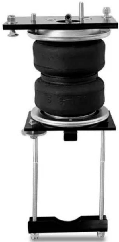
natural_image
Mechanical testing device with black and metallic components mounted on a black base (no visible text or symbols)BEHÖVS HJÄLP? KONTAKTA OSS!
fig. 1
KOMMA IGÅNG
natural_image
Diagram of a vehicle suspension system with two car wheels and a red manual lift (no text or labels)fig. 2
fig. 4
Höger
(passagerarens)
sidomontering
fig. 10
fig. 11
natural_image
Close-up of a mechanical component with red arrows pointing to features, labeled 'fig. 12' (no readable text or symbols)natural_image
Two cylindrical mechanical components mounted on metal plates, no visible text or symbolsHöger (passagerarens) sidomontering
fig. 14
FÄSTNING AV ENHETERNA PÅ RAMEN
natural_image
Close-up of a vehicle's lower suspension system with visible tire, car chassis, and mechanical components (no text or symbols)fig. 15
natural_image
Close-up of a hand adjusting a mechanical component with bolts and a metal bracket (no visible text or symbols)fig. 16
natural_image
Close-up of a mechanical assembly with bolts and a black bracket (no visible text or symbols)* For LoadLifter Ultimate Plus kits, the recommended location for the Schrader valves is the rear bumper area or license plate.
A. Inside fuel
tank filler
door
B. Inside rear wheel wells
C. License plate or rear bumper area*
fig. 20

CAUTION
HÅLL MINST 6" AVSTÅND MELLAN ALL LUFT
LINJER OCH AVGASSYSTEMET. UNDVIK SKARPA
BÖJAR OCH KANTER.
INSTALLERA NYLON AIR LINES
INSTALLERA FLÄTADE LUFTLEDNINGAR AV ROSTFRITT STÅL

CAUTION
HÄLL LUFTLEDNINGEN BORTA FRÅN BRÄNSLELEDNINGEN, BROMS LINJER OCH ELEKTRISKA LEDNINGAR.
Air Line Setup Without Compressor System

Air Line Setup for Compressor Integration

fig. 24
Färdiga installationsfoton
natural_image
Close-up of a car brake system with suspension components and wiring (no visible text or symbols)Left (driver's) side top view
natural_image
Close-up of a vehicle chassis frame with mounting hardware and bolts (no visible text or symbols)Right (passenger's) side top view
fig. 26

natural_image
Close-up of a vehicle suspension system with visible mechanical components and wiring (no text or symbols)Left (driver's) side back view shown with tire removed

natural_image
Close-up of a car suspension system with visible springs and wiring (no text or symbols)Right (passenger's) side view shown with tire removed
fig. 28
INNAN ANVÄNDNING
KONTROLLERA FÖR LÄCKOR
KLIPP INTE AV LUFTLEDNINGEN VID ARMATUREN PÅ ATT DETTA
KUNDE NICK
HYLLING OCH GÖR BESÄTTNINGEN ANVÄNDbar.
INSTALLATIONSCHECKLISTA
Minimum Recommended Pressure
5 PSI (.34BAR)
Maximum Air Pressure
100 PSI (7BAR)
RIKTLINJER FÖR UNDERHÅLL
natural_image
Side view line drawing of a car with a large rectangular vehicle (no text or symbols)Bottoming out
natural_image
Front view line drawing of a pickup truck (no text or symbols)Unlevel

natural_image
Front view line drawing of a pickup truck (no text or symbols)Level
fig. 33
fig. 32
Felsökningsguide
C/O YH Consulting Limited Office 147,
Centurion House, London Road,
Staines-upon-Thames, Surrey, TW18 4AX
| EC | REP |
E-CrossStu GmbH
Mainzer Landstr.69,
60329 Frankfurt am Main.
VEVOR®
TOUGH TOOLS, HALF PRICE
www.vevor.com/support