7X1232 - Air suspension kit Vevor - Free user manual and instructions
Find the device manual for free 7X1232 Vevor in PDF.

| Brand | Vevor |
| Model | 7X1232 |
| Product Type | Air Suspension Kit |
| Compatible Vehicles | GMC Sierra 1500 and Chevrolet Silverado 1500 (2007-2018), 2WD and 4WD |
| Rated Load | 5000 lb (approx 2268 kg) |
| Working Pressure | 5-100 psi (0.35-6.9 bar) |
| Number of Air Springs | 2 |
| Air Tube Diameter | 1/4 inch (6.35 mm) |
| Valve Type | 1/4" Schrader Valve |
| Kit Contents | Air springs, brackets, straps, clamps, heat shield, T-valve, fittings, tubing, instructions |
| Storage Temperature | -15°C to 50°C (5°F to 122°F) |
| Maintenance | Check air pressure weekly; use soapy water to detect leaks |
| Safety | Do not exceed GVWR; wear protective equipment; disconnect battery before electrical work |
| Installation | Remove original rubber bump stops, attach upper and lower brackets, assemble air springs, route air tubing, and install Schrader valve |
| Technical Support | www.vevor.com/support |
| Warranty | Electronic warranty certificate available on Vevor website |
| Manufacturer | Shanghaimuxinmuyeyouxiangongsi, Shanghai, China |
| Importers | SIHAO PTY LTD (Australia), Sanven Technology Ltd (United States), YH CONSULTING LIMITED (United Kingdom) |
Frequently Asked Questions - 7X1232 Vevor
User questions about 7X1232 Vevor
0 question about this device. Answer the ones you know or ask your own.
Ask a new question about this device
Download the instructions for your Air suspension kit in PDF format for free! Find your manual 7X1232 - Vevor and take your electronic device back in hand. On this page are published all the documents necessary for the use of your device. 7X1232 by Vevor.
USER MANUAL 7X1232 Vevor
Technical Support and E-Warranty Certificate www.vevor.com/support
Air Bag Suspension Kit
MODEL: 7X1232
We continue to be committed to provide you tools with competitive price. "Save Half", "Half Price" or any other similar expressions used by us only represents an estimate of savings you might benefit from buying certain tools with us compared to the major top brands and does not necessarily mean to cover all categories of tools offered by us. You are kindly reminded to verify carefully when you are placing an order with us if you are actually saving half in comparison with the top major brands.
VEVOR®
TOUGH TOOLS, HALF PRICE
Air Bag Suspension Kit
MODEL:7X1232
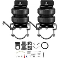
natural_image
Two black automotive lift actuators with metal clamps and mounting brackets, shown from different angles (no text or symbols visible)NEED HELP? CONTACT US!
Have product questions? Need technical support? Please feel free to contact us:
Technical Support and E-Warranty Certificate www.vevor.com/support
This is the original instruction, please read all manual instructions carefully before operating. VEVOR reserves a clear interpretation of our user manual. The appearance of the product shall be subject to the product you received. Please forgive us that we won't inform you again if there are any technology or software updates on our product.
Thank you for purchasing the 7X 1232 Kit! Please kindly be advised to read the instructions carefully before installing the air spring kit.
CAUTION:
Damage to the vehicle and air suspension system can be incurred if work is carried out in a manner other than specified in the instructions or in a different sequence.
- Not to be stored below 5^(-15^) or above 122^(50^) .
- Avoid damage to airlines and cables.
- Use car manufacturer's diagnostic software.
- Removal and installation are only to be performed by fully qualified personnel.

The air suspension system is under pressure (up to 10 bar, or 150 lbf/in).
Do not allow dirt or grease to enter the system. Always wear standard hand, ear, and eye protection when servicing the air suspension system. Verify pressure has been relieved and disconnect power to the air suspension system prior to disassembly. To avoid the possibility of short circuits while working with electric components consult your vehicle owner's manual on how to disconnect your battery.

Consult your vehicle owner's manual, service manual, or car dealer for the correct jacking points on your vehicle and for additional care, safety, and maintenance instructions. Under no circumstances should any work be completed underneath the vehicle if it is not adequately supported, as serious injuries and death can occur.
PARAMETER LIST
| Model | standard |
| Adapted models | 2007 - 2018 GMC Sierra 1500 2WD & 4WD2007 - 2018 Chevrolet Silverado 1500 2WD & 4WD |
| rated load (lbs) | 5000 |
| Use the pressure (psi) | 5-100 |
PARTS LIST
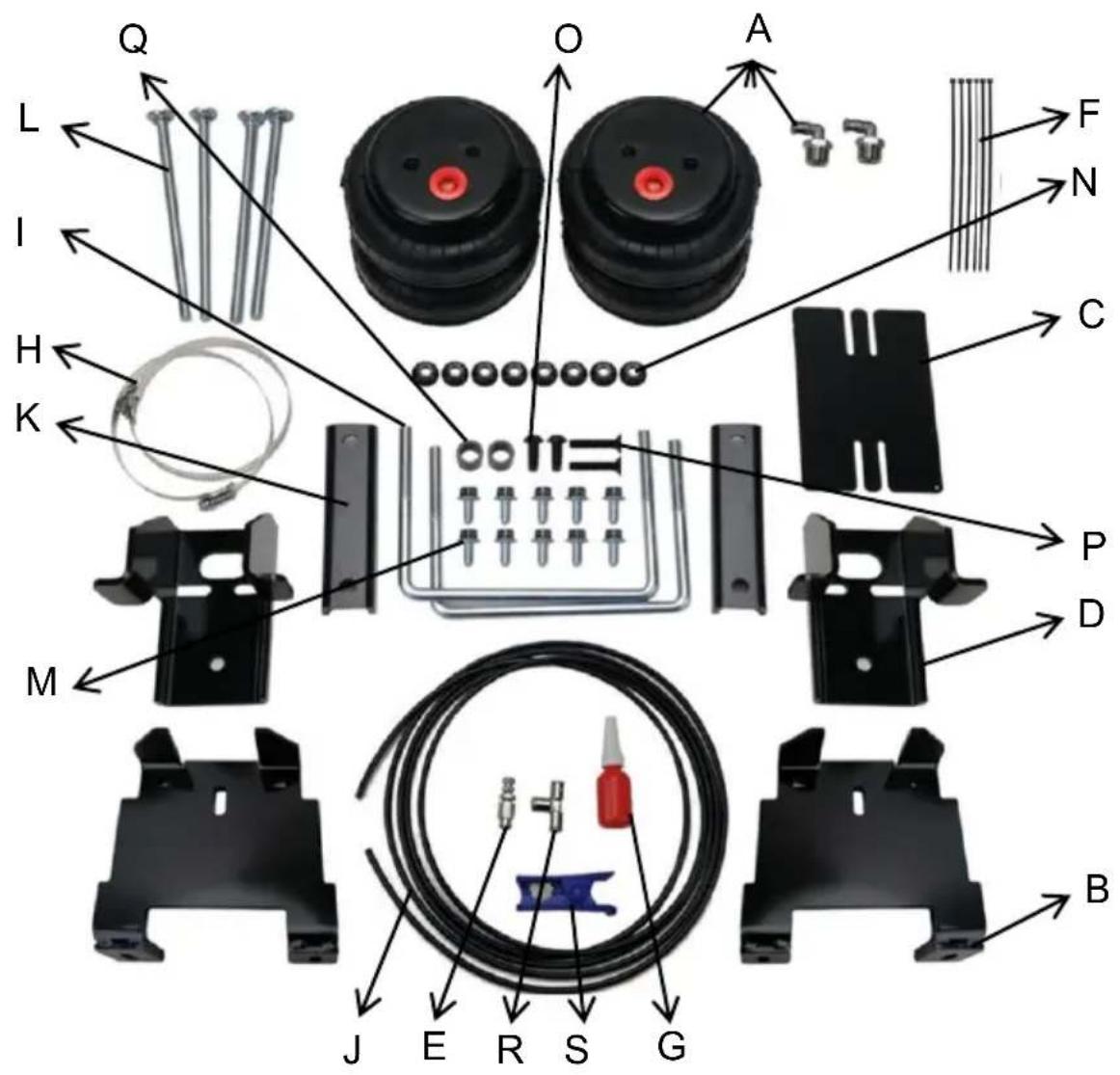
| ITEM | DESCRIPTION | QUANTITY | ITEM | DESCRIPTION | QUANTITY |
| A | Airbags | 2 | K | Bracket Strap | 2 |
| B | Lower Bracket | 2 | L | 3/8"-16 x6"CARRIAGE BOLT | 4 |
| C | Heat Shield | 1 | M | 3/8"-16 x 3/4" FLANGED HEX BOLT | 10 |
| D | Upper Bracket | 2 | N | 3/8"-16 FLANGED NUT | 8 |
| E | 1/4" Schrader valve | 1 | O | M10*25 Round head hexagonal bolt | 2 |
| F | Tie straps | 6 | P | M10*50 FLAT HEAD ALLEN BOLT | 2 |
| G | Thread adhesive | 1 | Q | SPACER | 2 |
| H | Metal Cable Zip Tie | 2 | R | 1/4" T- Valve | 1 |
| I | BAIL CLAMP | 2 | S | Tracheal scissors | 1 |
| J | 1/4" DOT Air Hose | 1 | T | Instructions | 1 |
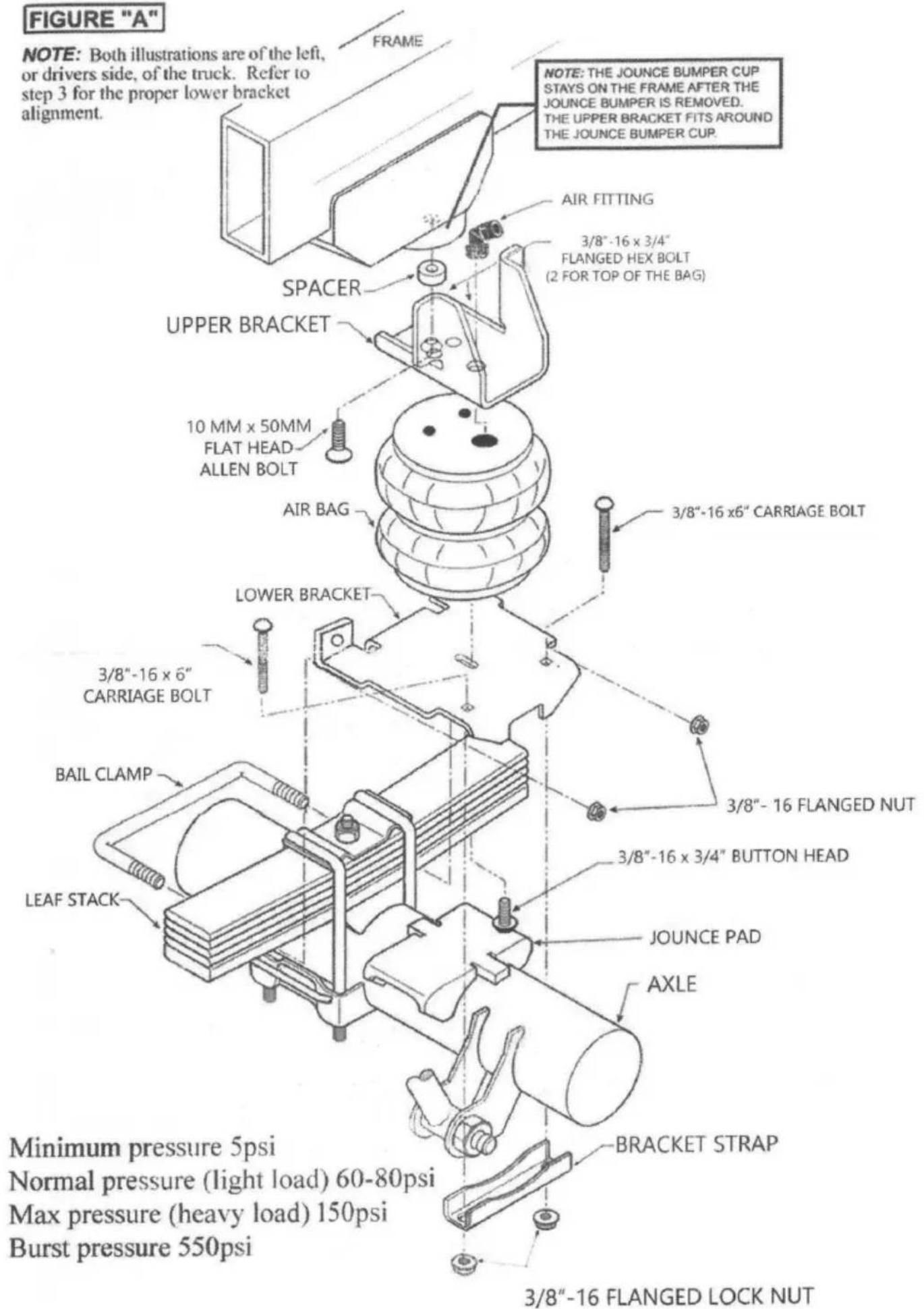
NOTE: Both illustrations are of the left, or drivers side, of the truck. Refer to step 3 for the proper lower bracket alignment.
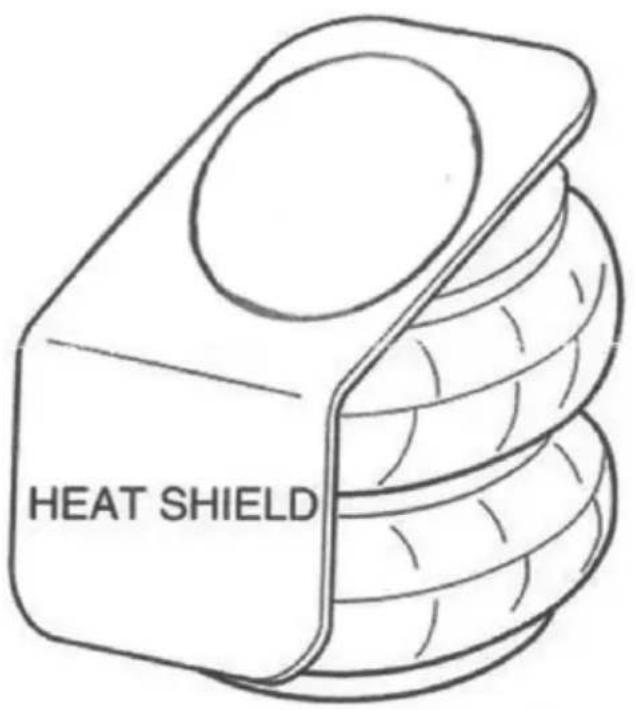
INSTALLING THE HEAT SHIELD
Find the closest point between the exhaust pipe and the air bag. Mount the hear shield in this spot.
ASSEMBLING AIR SPRING BAGS & BRACKETS
Step 1- Prepare The Vehicle/Upper Bracket Installation
Your vehicle is equipped with rubber jounce bumpers. The bumpers are attached to the frame directly above the axle. Remove these Bumpers by unbolting them from the frame. This bumper will not be reused with this kit.
Note: The Bolt Used To Hold The Jounce Bumper In Place May Bea Flat Head Or Hex Head, Depending On The Year Of Your Truck.
Attach the upper brackets to the frame where the jounce bumper was removed using the 10MM x 50 MM flat head bolt, placing the spacer between the upper bracket and the frame, as shown in Figure 'A'.
Step 2- Put Together The Air Bag Assembly
Installation will begin with the left side of the vehicle. All pictures depict the installation on the left side of the vehicle unless noted otherwise. Attach the lower
bracket to the air bag using a 3/4' flange hex bolt. Donot fully tighten the bolt to allow the lower bracket to rotate for installation. See Figures "A" & "B".
Minimum pressure 5psi Normal air pressure 60-80psi Max pressure 150psi (under full load) Burst pressure 550psi
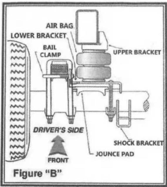
Step 3- Install The Assembly To The Vehicle
Place the air bag assembly on top of the jounce bumper pad on the axle housing, making sure the bracket is pushed flush to the leaf stack. Bolt on air bag to the upper bracket. See Figures "A"& "B". Install the air fitting into the air bag and tighten it. Use vigor thread sealer on the threads (allow to cure for 24 hours before inflating the bags). Adjust the air bag to the upper bracket to provide the best alignment. Secure using 3/8--16 x 3/4" flanged hex bolts. On the driver's side only, the parking brake line will need to be zip-tied to the upper bracket see, Figure "A". With the assembly attached to the frame rail, the next step is to secure the lower bracket to the vehicle. Install the bail clamp under the leaf springs from the outside of the leaf stack and through the holes in the legs of the lower bracket. Secure (hand tight) using the 3/8"-16 flange nuts. Begin to tighten the nuts on the bail clamp first, to draw the bracket towards the leaf stack, making sure the bracket fits around the u-bolts. Alternate to the bracket strap until the bracket is secured. See Figures "A"& "B". Important: In Order For The Air Bag To Function Properly, There Must Be a Minimum Of 1/2" Of Clearance Around The Air Bag.
Step 4- Install The Passenger'S Side Assembly
Follow steps 2 & 3 for installation of the passenger's side assembly.
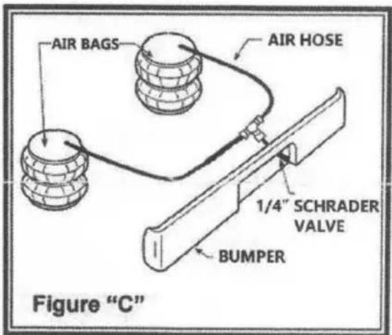
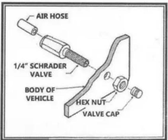
Step 5- Install The Air Hose And Schrader Valve
Uncoil the air hose and cut it into two equal lengths. DO NOT FOLD OR
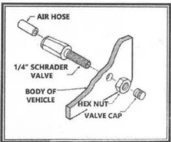
KINK THE HOSE. Make the cut as straight as possible, using a hose cutter. Insert one end of the hose into the push-to-connect fitting installed on the top of the air bag. Select a location on the vehicle for the Schrader valve. The location can be on the bumper or the body of the vehicle, as long as it is in a protected location so the valve will not be damaged, but maintain still accessibility for the air chuck, see Figure "C". Drill a 5/16' hole and install the Schrader valve. Run the tubing from the air bag to the tee and to the valve, routing it to avoid direct heat from the engine, exhaust pipe, and away from sharp edges. Use thermal sleeves if the hose is run near these conditions. The air hose should not be bent or curved sharply as it may buckle.
Secure the hose in place with the nylon zip ties provided. Push the end of the air hose into the schrader valve.
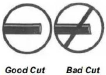
WHEN CUTTING OR TRIMMING THE AIR LINE, USE A HOS CUTTER, A RAZOR BLADE, OR A SHARP KNIFE. A CLEAN, SQUARE CUT WILL ENSURE
AGAINST LEAKS. DON'T USE WIRE CUTTERS OR SCISSORS TO CUT THE AIR LINE. THESE MAY FLATTEN OR CRIMP THE AIR LINE CAUSING IT TO LEAK AROUND THE O-RING SEAL INSIDE THE ELBOW FITTING.
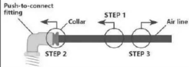
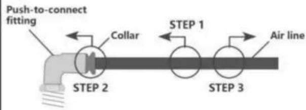
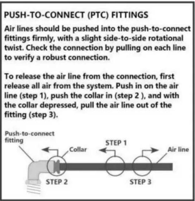
PUSH-TO-CONNECT (PTC) FITTINGS
Air lines should be pushed into the push-to-connect fittings firmly, with a slight side-to-side rotational twist. Check the connection by pulling on each line to verify a robust connection.
To release the air line from the connection, first release all air from the system. Push in on the air line (step 1), push the collar in (step 2), and with the collar depressed, pull the air line out of the fitting (step 3).
GUIDE LINE FOR ADDING AIR
- Start with the vehicle level or slightly above.
- When In doubt, always add air.
- If the front of the vehicle dives while braking, increase the pressure Si the front air bag if equipped.
- If it is ever suspected that the at bags have bottomed out Increase the pressure.
- Adjust the pressure up and down to find the best ride.
- It may be necessary to maintain different pressures on each side of the vehicle Loads such as water, fuel, and appliances will cause the vehicle to be heavier on one side. As much as a 50 PSI and appliances will cause the vehicle to be heavier on one side. As much as a 50 PSI difference is not uncommon. (additional schrader valves can be purchased at www.vigorairride.com)
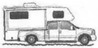
natural_image
Side view illustration of a compact car with a large open cab (no text or symbols visible)Bottoming out
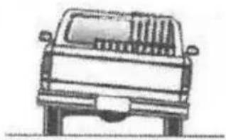
natural_image
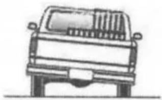
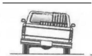
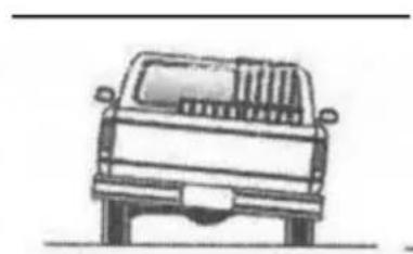
Front view line drawing of a vehicle (no text or symbols)Unlevel
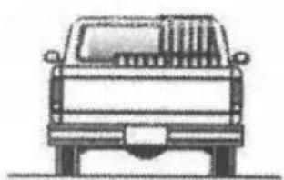
natural_image
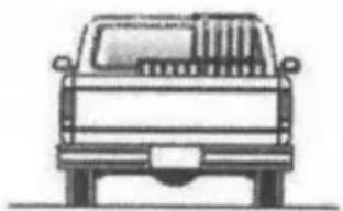
Front view line drawing of a pickup truck (no text or symbols)Level
By following the steps below, vehicle owners will obtain the longest life and best result from their air springs.
- Check the air pressure weekly.
-
Always maintain normal ride height.
-
If you develop an air leak In the system, use a soapy water solution (1 part dish soap. 4 parts water) to check all air fine connections and the Inflation valve core before deflating and removing the air spring.
- When increasing load, always adjust the air pressure to maintain the normal ride height. Increase or decrease pressure from the system as necessary to attain normal ride height for optimal ride and handling. Remember that loads carried behind the aide (including tongue loads) require more levelling force (pressure) than those carried directly over the axle
FOR YOUR SAFETY AND TO PREVENT POSSIBLE DAMAGE TO YOUR VEHICLE, DO NOT EXCEED THE MAXIMUM GROSS VEHICLE WEIGHT RATING
(GVWR). AS INDICATED BY THE VEHICLE MANUFACTURER.
IMPORTANT SAFETY NOTICE :
The installation of this kit does not alter the Gross Vehicle Weight Rating (GVWR) or payload of the vehicle. Check your vehicle's owner's manual and do not exceed the maximum load listed lot your vehicle.
Gross Vehicle Weight Paling:
The maximum allowable weight of the fully-loaded vehicle (including passengers and cargo) This number — along with other weight limits. as well as tire, rim size and inflation pressure data — Is shown on the vehicle's Safely Compliance Certification Label.

Please make sure that you have tightened all the nuts and bolts to the manufacturer's specifications.
Manufacturer: Shanghaimuxinmuyeyouxiangongsi
Address: Shuangchenglu 803nong11hao1602A-1609shi, baoshanqu, shanghai 200000 CN.
Imported to AUS: SIHAO PTY LTD. 1 ROKEVA STREETEASTWOOD NSW 2122 Australia
Imported to USA: Sanven Technology Ltd. Suite 250, 9166 Anaheim Place, Rancho Cucamonga, CA 91730
| UK | REP |
YH CONSULTING LIMITED.
C/O YH Consulting Limited Office 147,
Centurion House, London Road,
Staines-upon-Thames, Surrey, TW18 4AX
| EC | REP |
E-CrossStu GmbH
Mainzer Landstr.69,
60329 Frankfurt am Main.
VEVOR®
TOUGH TOOLS, HALF PRICE
Technical Support and E-Warranty Certificate
www.vevor.com/support
VEVOR®
TOUGH TOOLS, HALF PRICE
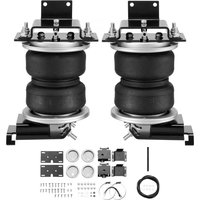
natural_image
Two identical black automotive lift actuators with mounting brackets and metal clamps, shown from different angles (no text or symbols visible)BESOIN D'AIDE? CONTACTEZ-NOUS!
INSTALLATION INSTRUCTIONS
INSTALLATION DU BOUCLIER THERMIQUE
Minimum pressure 5psi Normal air pressure 60-80psi Max pressure 150psi (under full load) Burst pressure 550psi
PUSH-TO-CONNECT (PTC) FITTINGS
Air lines should be pushed into the push-to-connect fittings firmly, with a slight side-to-side rotational twist. Check the connection by pulling on each line to verify a robust connection.
To release the air line from the connection, first release all air from the system. Push in on the air line (step 1), push the collar in (step 2), and with the collar depressed, pull the air line out of the fitting (step 3).

LIGNE DE GUIDAGE POUR L'AJOUT D'AIR
natural_image
Side view line drawing of a flatbed camper van (no text or symbols)Toucher le fond
natural_image
Front view line drawing of a pickup truck (no text or symbols)Unlevel

natural_image
Front view line drawing of a pickup truck (no text or symbols)Niveau
C/O YH Consulting Limited Bureau 147,
Maison Centurion, London Road,
Staines-upon-Thames, Surrey, TW18 4AX
| EC | REP |
E-CrossStu GmbH
Mainzer Landstr.69,
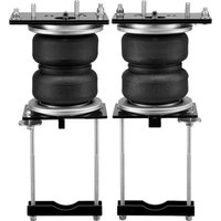
natural_image
Two identical black automotive lift actuators with adjustable arms and mounting brackets (no text or symbols visible)BRAUCHEN SIE HILFE? KONTAKTIERE UNS!
INSTALLATION INSTRUCTIONS
Minimum pressure 5psi Normal air pressure 60-80psi Max pressure 150psi (under full load) Burst pressure 550psi

PUSH-TO-CONNECT (PTC) FITTINGS
Air lines should be pushed into the push-to-connect fittings firmly, with a slight side-to-side rotational twist. Check the connection by pulling on each line to verify a robust connection.
To release the air line from the connection, first release all air from the system. Push in on the air line (step 1), push the collar in (step 2), and with the collar depressed, pull the air line out of the fitting (step 3).

RICHTLINIE ZUM LUFTHINZUFÜGEN
natural_image
Side view line drawing of a flatbed camper van with a large cab (no text or symbols)natural_image
Front view line drawing of a pickup truck (no text or symbols)Uneben

natural_image
Front view line drawing of a pickup truck (no text or symbols)Ebene
C/O YH Consulting Limited Büro 147,
Centurion House, London Road,
Staines-upon-Thames, Surrey, TW18 4AX
| EC | REP |
E-CrossStu GmbH
Mainzer Landstr.69,
60329 Frankfurt am Main.
VEVOR®
TOUGH TOOLS, HALF PRICE
www.vevor.com/support
VEVOR®
TOUGH TOOLS, HALF PRICE
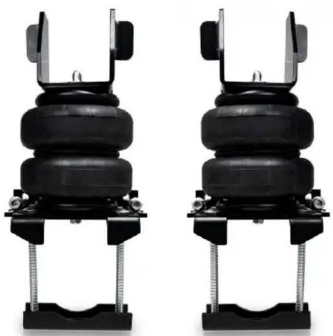
natural_image
Two identical black automotive lift actuators with mounting brackets and metal clamps, shown from different angles (no text or symbols visible)HO BISOGNO DI AIUTO? CONTATTACI!
INSTALLATION INSTRUCTIONS
Minimum pressure 5psi Normal air pressure 60-80psi Max pressure 150psi (under full load) Burst pressure 550psi
PUSH-TO-CONNECT (PTC) FITTINGS
Air lines should be pushed into the push-to-connect fittings firmly, with a slight side-to-side rotational twist. Check the connection by pulling on each line to verify a robust connection.
To release the air line from the connection, first release all air from the system. Push in on the air line (step 1), push the collar in (step 2), and with the collar depressed, pull the air line out of the fitting (step 3).

natural_image
Side view line drawing of a compact car with a large open cab (no text or symbols)
natural_image
Front view line drawing of a pickup truck (no text or symbols)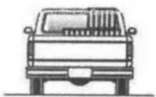
natural_image
Front view line drawing of a pickup truck (no text or symbols)Toccare il fondo
Importato in AUS: SIHAO PTY LTD. 1 ROKEVA STREETEASTWOOD NSW 2122
Australia
C/O YH Consulting Limited Ufficio 147,
Casa del Centurione, London Road,
Staines-upon-Thames, Surrey, TW18 4AX
| EC | REP |
E-CrossStu GmbH
Mainzer Landstr.69,
natural_image
Two identical black automotive lift actuators with mounting brackets and metal clamps, shown from different angles (no text or symbols visible)INSTALLATION INSTRUCTIONS
Minimum pressure 5psi Normal air pressure 60-80psi Max pressure 150psi (under full load) Burst pressure 550psi

PUSH-TO-CONNECT (PTC) FITTINGS
Air lines should be pushed into the push-to-connect fittings firmly, with a slight side-to-side rotational twist. Check the connection by pulling on each line to verify a robust connection.
To release the air line from the connection, first release all air from the system. Push in on the air line (step 1), push the collar in (step 2), and with the collar depressed, pull the air line out of the fitting (step 3).

LÍNEA GUÍA PARA AÑADIR AIRE
natural_image
Side view line drawing of a vintage minibus with a flat roof and open cabin (no text or symbols)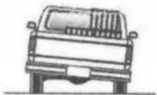
natural_image
Front view line drawing of a pickup truck (no text or symbols)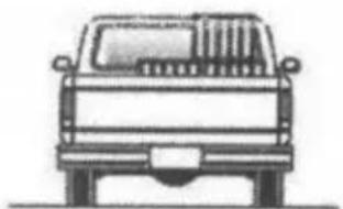
natural_image
Front view line drawing of a classic pickup truck (no text or symbols)Casa Centurión, London Road,
Staines upon Thames, Surrey, TW18 4AX
| EC | REP |
E-CrossStu GmbH
Mainzer Landstr.69,
natural_image
Two identical black rubber car lifters mounted on metal supports, no text or symbols visible.POTRZEBUJE POMOCY? SKONTAKTUJ SIĘ Z NAMI!
INSTALLATION INSTRUCTIONS
MONTAŻ OSŁONY CIEPLNEJ
Minimum pressure 5psi Normal air pressure 60-80psi Max pressure 150psi (under full load) Burst pressure 550psi

Air lines should be pushed into the push-to-connect fittings firmly, with a slight side-to-side rotational twist. Check the connection by pulling on each line to verify a robust connection.
To release the air line from the connection, first release all air from the system. Push in on the air line (step 1), push the collar in (step 2), and with the collar depressed, pull the air line out of the fitting (step 3).

WSKAZÓWKA DLA DOLEWANIA POWIETRZA
natural_image
Side view illustration of a vintage-style camper van with a flat roof and two windows (no text or symbols)Osiągnięcie dna
natural_image
Front view line drawing of a vehicle (no text or symbols)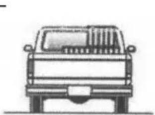
natural_image
Front view line drawing of a pickup truck (no text or symbols)C/O YH Consulting Limited Biuro 147,
Dom Centuriona, London Road,
Staines-upon-Thames, Surrey, TW18 4AX
| EC | REP |
E-CrossStu GmbH
Mainzer Landstr.69,
60329 Frankfurt nad Menem.
VEVOR®
TOUGH TOOLS, HALF PRICE
www.vevor.com/support
VEVOR®
TOUGH TOOLS, HALF PRICE
Technische ondersteuning en e-garantiecertificaat www.vevor.com/support
Airbagophangingsset
MODEL: 7X1232
natural_image
Two identical black automotive lift actuators with mounting brackets and metal clamps, shown from different angles (no text or symbols visible)HULP NODIG? NEEM CONTACT MET ONS OP!
| ARTIKELBESCHRIJVING AANTAL ARTIKELBESCHRIJVING AANTAL | |||||
| A | Airbags | 2 | K | Beugel riem | 2 |
| B Onderbeugel | 2 | L | 3/8"-16x6"VERVOER BOUT | 4 | |
| Hitteschild | 1 | M | 3/8"-16 x 3/4"GEFLENSDE ZESKANTC BOUT | 10 | |
| D Bovenbeugel | 2 | N | 3/8"-16 MET FLENS NOOT | 8 | |
| EN | 1/4" Schrader ventiel | 1 | O | M10*25 Rond hoofd zeshoekig bout | 2 |
| F | Bindbanden | 6 | P | M10*50 PLATHOOFD ALLEN WINKEL | 2 |
| G | Draad Zelfklevend | 1 | Q | SPACER | 2 |
| H | Metalen kabelrits Stropdas | 2 | R | 1/4" T-ventiel | 1 |
| I | BORGKLEM | 2 | S | Tracheale schaar | 1 |
| J | 1/4" DOT-lucht Slang | 1 | T | Instructies | 1 |

INSTALLATION INSTRUCTIONS
Minimum pressure 5psi Normal air pressure 60-80psi Max pressure 150psi (under full load) Burst pressure 550psi
Air lines should be pushed into the push-to-connect fittings firmly, with a slight side-to-side rotational twist. Check the connection by pulling on each line to verify a robust connection.
To release the air line from the connection, first release all air from the system. Push in on the air line (step 1), push the collar in (step 2), and with the collar depressed, pull the air line out of the fitting (step 3).
RICHTLIJNEN VOOR HET TOEVOEGEN VAN LUCHT
natural_image
Side view illustration of a vintage-style camper van with a flat roof and two windows (no text or symbols)natural_image
Front view line drawing of a pickup truck (no text or symbols)
natural_image
Front view line drawing of a pickup truck (no text or symbols)NiveauOngelijk
C/O YH Consulting Limited Kantoor 147,
Centurion House, Londen Road,
Staines-upon-Thames, Surrey, TW18 4AX
| EC | REP |
E-CrossStu GmbH
Mainzer Landstr.69,
60329 Frankfurt am Main.
VEVOR®
TOUGH TOOLS, HALF PRICE
Technische ondersteuning en e-garantiecertificaat www.vevor.com/support
VEVOR®
TOUGH TOOLS, HALF PRICE
natural_image
Two identical black automotive lift actuators with mounting brackets and metal clamps, shown from different angles (no text or symbols visible)BEHÖVS HJÄLP? KONTAKTA OSS!
| ARTIKEL BESKRIVNING ANTAL ARTIKEL BESKRIVNING ANTAL | |||||
| A | Krockkuddar | 2 | K | Fästrem | 2 |
| B Nedre fäste | 2 | L | 3/8"-16x6" VAGNBULT | 4 | |
| C FLÄNSÄVärnHESKöld | 1 | M | 3/8"-16 x 3/4"BULT | 10 | |
| D Övre fäste | 2 | N | 3/8"-16 FLÄNSADNÖT | 8 | |
| GCH | 1/4" Schraderventil | 1 | O | M10*25 Rundhuvud sexkantigtbult | 2 |
| F | Knytband | 6 | P | M10*50 LÄTTHUVUDALLEN SHOP | 2 |
| G | Trådlim | 1 | Q | SPACER | 2 |
| H | MetallkabeldragkedjaSlips | 2 | R | 1/4" T-ventil | 1 |
| .1 | BÖRNINGSKÄLL | 2 | S | Trakeal sax | |
| J | 1/4" DOT AirSlang | 1 | T | Instruktioner | 1 |

INSTALLATION INSTRUCTIONS
INSTALLATION AV VÄRMESKÖLD
Minimum pressure 5psi Normal air pressure 60-80psi Max pressure 150psi (under full load) Burst pressure 550psi
RIKTLINJ FÖR ATT TILLFÖRA LUFT
natural_image
Side view illustration of a vintage-style camper van with a trailer and cabin (no text or symbols)Bottnar
natural_image
Front view line drawing of a vehicle (no text or symbols)Ojämn
natural_image
Front view line drawing of a pickup truck (no text or symbols)Nivå
C/O YH Consulting Limited Office 147,
Centurion House, London Road,
Staines-upon-Thames, Surrey, TW18 4AX
| EC | REP |
E-CrossStu GmbH
Mainzer Landstr.69,
60329 Frankfurt am Main.
VEVOR®
TOUGH TOOLS, HALF PRICE
www.vevor.com/support