SSG-06 - Toys Vevor - Free user manual and instructions
Find the device manual for free SSG-06 Vevor in PDF.


User questions about SSG-06 Vevor
0 question about this device. Answer the ones you know or ask your own.
Ask a new question about this device
Download the instructions for your Toys in PDF format for free! Find your manual SSG-06 - Vevor and take your electronic device back in hand. On this page are published all the documents necessary for the use of your device. SSG-06 by Vevor.
USER MANUAL SSG-06 Vevor
Technical Support and E-Warranty Certificate
www.vevor.com/support
We continue to be committed to provide you tools with competitive price.
"Save Half", "Half Price" or any other similar expressions used by us only represents an estimate of savings you might benefit from buying certain tools with us compared to the major top brands and does not necessarily mean to cover all categories of tools offered by us. You are kindly reminded to verify carefully when you are placing an order with us if you are actually Saving Half in comparison with the top major brands.
VEVOR®
TOUGH TOOLS, HALF PRICE
natural_image
Line drawing of a mechanical device with a circular component and mounting bracket (no text or symbols)NEED HELP? CONTACT US!
Have product questions? Need technical support? Please feel free to contact us: Technical Support and E-Warranty Certificate www.vevor.com/support
This is the original instruction, please read all manual instructions carefully before operating. VEVOR reserves a clear interpretation of our user manual. The appearance of the product shall be subject product you received. Please forgive us that we won't inform you again if there are any technology software updates on our product.
TIPS
Assembling this Score Arcade Game machine will take approximately 3 hours, it is recommended that operate it.
SAFETY INSTRUCTIONS
Thank you for using this product. Please read all of the instructions before using it. The information you achieve the best possible results.
WARNING:
Please read this manual carefully before using the product. Failure to do so may result in serious in
| Warning-To reduce the risk of injury, user must read instructions manual carefully. | |
| CE | Compliance is a EC security certification. |
| CORRECT DISPOSALThis product is subject to the provision of european Directive 2012/19/EU. The symbol show wheelie bin crossed through indicates that the product requires separate refuse collection in European Union. This applies to the product and all accessories marked with this symbol. Products marked as such may not be discarded with normal domestic waste, but must be acollection point for recycling electrical and electronic devices. | |
| FC | FCC Information:CAUTION: Changes or modifications not expressly approved by the party responsible for compliance could void the user's authority to operate the equipment!This device complies with Part 15 of the FCC Rules. Operation is subject to the following conditions:1) This product may cause harmful interference.2) This product must accept any interference received, including interference that may cause undesired operation.WARNING: Changes or modifications to this product not expressly approved by the party.responsible for compliance could void the user's authority to operate the product.Note: This product has been tested and found to comply with the limits for a Class B digital device pursuant to Part 15 of the FCC Rules, These limits are designed to provide reasonable pr against harmful interference in a residential installation.This product generates, uses and can radiate radio frequency energy, and if not installed a used in accordance with the instructions, may cause harmful interference to radio communications. However, there is no guarantee that interference will not occur in a partici installation. If this product does cause harmful interference to radio or television reception,wh can be determined by turning the product off and on, the user is encouraged to try to cc interference by one or more of the following measures.Reorient or relocate the receiving antenna.Increase the distance between the product and receiver.Connect the product to an outlet on a circuit different from that to which the receiver is connected.Consult the dealer or an experienced radio/TV technician for assistance. |
ASSEMBLY PRECAUTIONS
- Assemble needs to follow these instructions. Incorrect assembly can be a hazard.
- Wear safety goggles and heavy-duty work gloves during assembly.
- Do not assemble when tired or under the influence of alcohol, drugs or medication.
- Weight capacity and other product capabilities only apply to a wholly and correctly assembled pro
-
Keep the assembly area clean and well-lit.
-
Keep bystanders out of the area during assembly.
- The weight of plate is heavy; pay attention to the installation to avoid hurting it, and if necessary someone to assist with the installation.
- Assembly should be done by adults only.
- WARNING: This product contains small parts. If swallowed, it will pose a choking hazard. Keep tl parts away from children when assembling!
- Before using the appliance for the first time, peel off any promotional materials and packaging n
ATTENTION!

WARNING! Keep children and pets away.
WARNING! Remove all packaging materials and keep them for future use. Packaging mater are not a toy.
WARNING! Don't let children play with the packaging materials. If they swallow the packaging materials, they will suffocate!
SAVE THESE INSTRUCTIONS
USE PRECAUTIONS
WARNING: TO PREVENT SERIOUS INJURY AND DEATH FROM TIPPING:
- To avoid accidents or sharp edges injuries please assemble and use carefully.
- Use as intended only. Do not sit or stand on the product.
- Inspect before every use. Do not use it if parts are loose or damaged.
- If any parts are missing, broken, damaged, or worn, stop using this item until repairs are made replacement parts are installed.
- Do not exceed the listed weight capacity. Tighten all knobs securely before applying load. Be aw dynamic loading! The sudden load movement may briefly create an excess load, causing product failure
- Try not to be too heavy to avoid the weight in one place, causing the table to overturn.
WARNING: Do not climb onto the machine to play, avoid flipping
HARDWARE IDENTIFIER (To Scale)
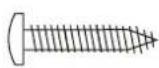
H1 - 3.5 mm x 18 mm Phillips Round Head Screw (24 pcs)
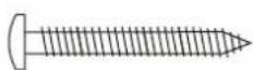
H2 - 3.5 mm x 28 mm Phillips Round Head Screw (28 pcs)
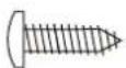
H3 - 3.5 mm x 12 mm Phillips Round Head Screw (98 pcs)
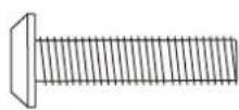
H4 - 6 mm x 25 mm Allen Head Bolt (16 pcs)
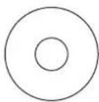
H5 - 6.5 mm x 18 mm Flat Washer (16 pcs)
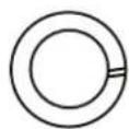
H6 - M6 Lock Washer (16 pcs)
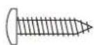
H7 - 3.5 mm x 14 mm Phillips Round Head Screw (12 pcs)
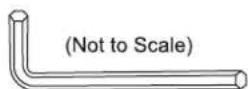
T1 - M6 Allen Wrench (1 pc)
PARTS IDENTIFIER
(Not to Scale)
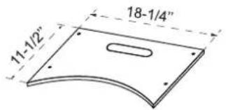
text_image
11-1/2" 18-1/4"P1 - Front Leg Apron (1 pc)
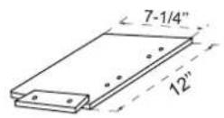
P2 - Left Front Leg (assembles with P17) (1 pc)
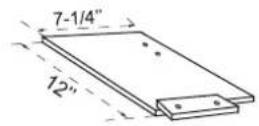
P3 - Right Front Leg (assembles with P18) (1 pc)
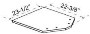
P4 - Ball Stop Bottom Board (1 pc)
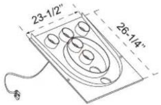
text_image
23-1/2" 26-1/4"P5 - Target Board with Scoring Sensors (1 pc)
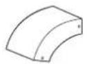
P6- Top Rail Plastic
Corner Cap
(2 pcs)
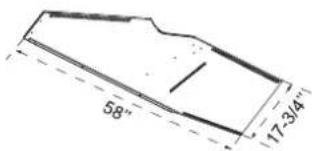
text_image
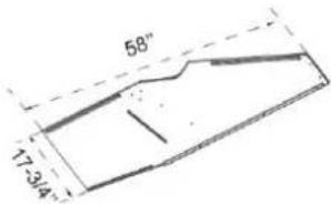
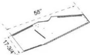
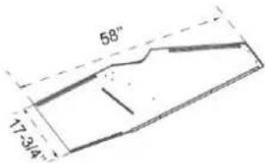
58" 17-3/4"P7 - Right Back Cabinet Leg (1 pc)
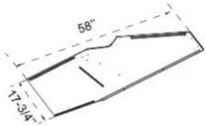
text_image
58" 17-3/4"P8 - Left Back Cabinet Leg (1 pc)
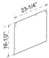
text_image
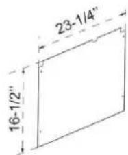
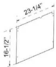
23-1/4" 16-1/2"P9 - Backboard with Graphic (1 pc)
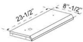
P10 - Top Cabinet Panel for Scorer (1 pc)
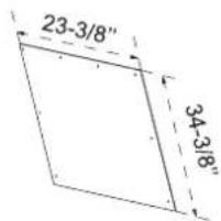
text_image
23-3/8" 34-3/8"P11 - Upper Back Cabinet Board (1 pc)
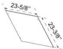
P12 - Lower Back Cabinet Board (1 pc)
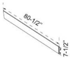
text_image
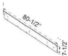
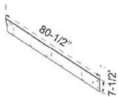
80-1/2" 7-1/2"P13 - Left Side Apron (1 pc)
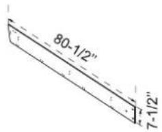
text_image
80-1/2" 7-1/2"P14 - Right Side Apron (1 pc)
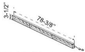
text_image
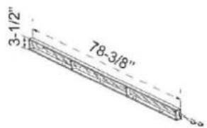
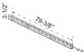
3-1/2" 78-3/8"(With ON/OFF switch+ wiring) P15 - Left Top Rail with Control Switch and Wiring (1 pc)
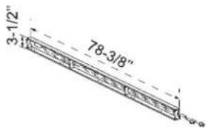
text_image
3-1/2" 78-3/8"P16 - Right Top Rail (1 pc)
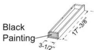
text_image
Black Painting 3-1/2" 17"-3/8"P17 - Left Leg (assembles with P2) (1 pc)
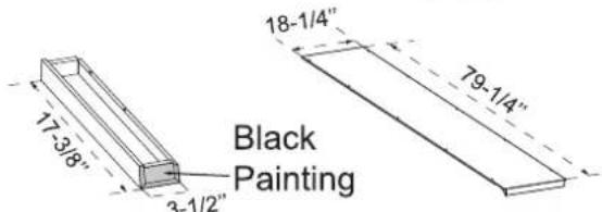
text_image
17-3/8" 3-1/2" Black Painting 18-1/4" 79-1/4"P18 - Right Leg (assembles with P3) (1 pc)
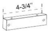
P20 - Wooden Support Brace (packed with black plastic "L" brackets) (1 pc)
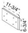
P21 - Connecting Board (2 pcs)
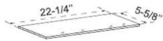
P22 - Goal Box
Bottom Board
(1 pcs)

P23 - Metal Connection Plate (16 pcs)
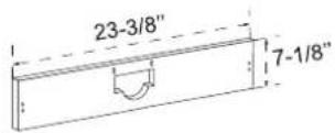
P24 - Middle Support Board (2 pcs)
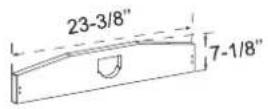
P25 - End Support Board (1 pc)
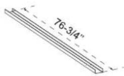
P26 - Plastic Ball Return (1 pc)
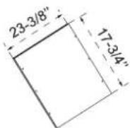
P27 - Clear Plexiglass (1 pc)
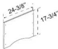
P28 - Lower Front Cabinet Board (1 pc)
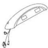
P29 - Electronic Scorer (1 pc)
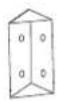
P30 - Black Plastic "L" Bracket (6 pcs)
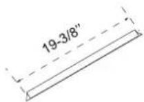
P31 - Left Plastic Trim Strip (1 pc)
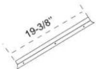
P32 - Right Plastic Trim Strip (1 pc)
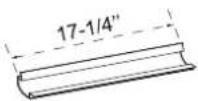
P33 - Plastic Connector (Playfield to Front Leg) (1 pc)
ACCESSORIES IDENTIFIER (Not to Scale)
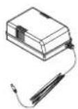
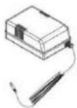
A1 - A/C Adapter (1 pc)

A2 - Ball (4 pcs)
PARTS REQUIRED
1pc - P13 Left Side Apron
10pcs - P23 Metal Connection Plate
1pc - P14 Right Side Apron
40pcs - H3 Phillips Round head Screw
1pc - P15 Left Top Rail with Control Switch
1pc - P16 Right Top Rail
STEP 1
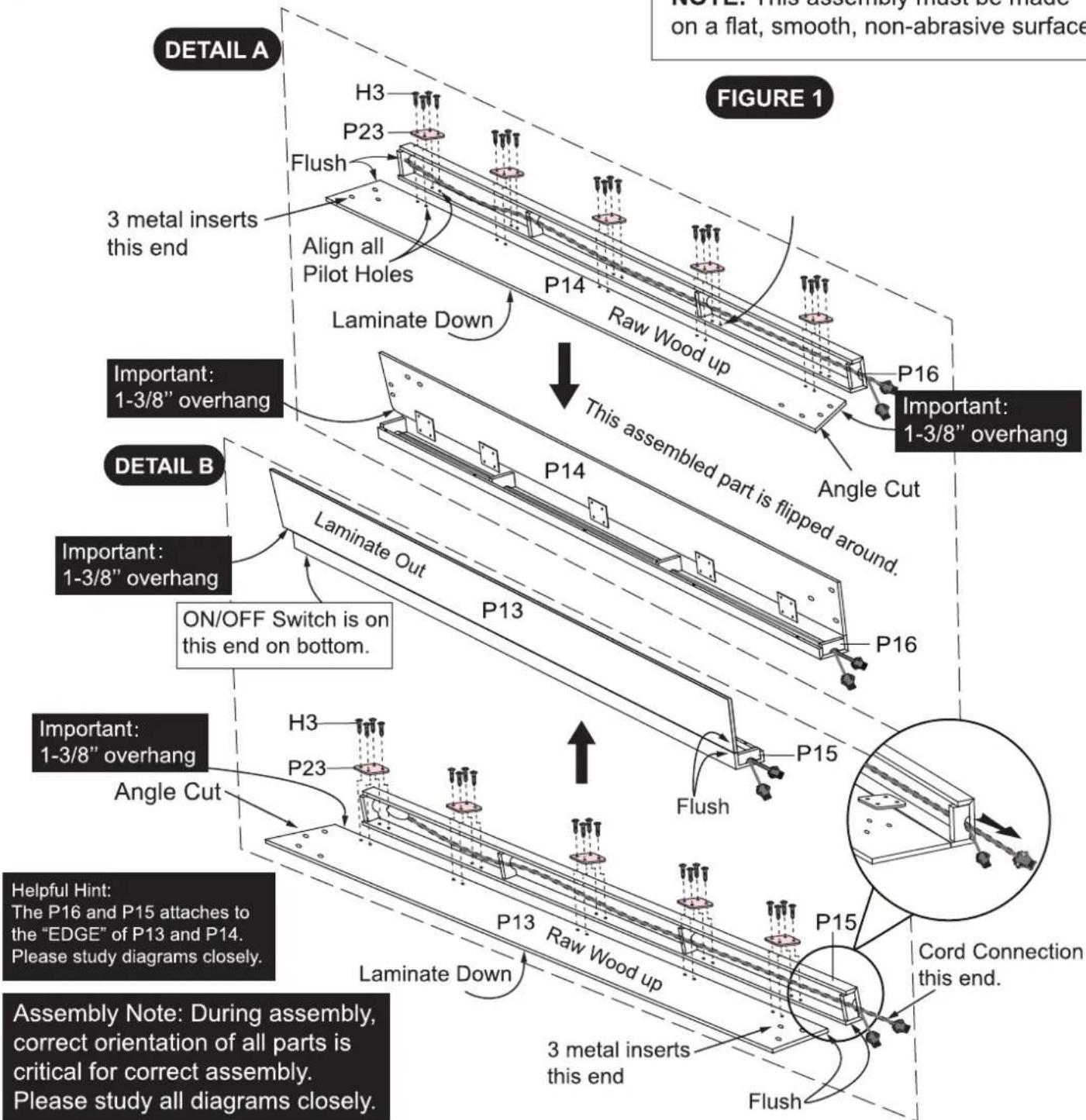
Attach the P14 Right Side Apron onto the P16 Right Top Rail using the P23 Metal Connection Plates and the pilot holes on the P14/P16, using the H3 Phillips Round Head Screws as shown in DETAIL A.
Attach the P13 Left Side Apron onto the P15 Left Top Rail using the P23 Metal Connection Plates and the pilot holes on P13/P15 ,using the H3 Phillips Round Head Screws as shown in DETAIL B.
Tighten, but DO NOT strip out H3 screws.
text_image
DETAIL A H3 P23 Flush 3 metal inserts this end Align all Pilot Holes Laminate Down P14 Raw Wood up P16 FIGURE 1 Important: 1-3/8" overhang This assembled part is flipped around. Angle Cut P14 P16 DETAIL B Important: 1-3/8" overhang ON/OFF Switch is on this end on bottom. Important: 1-3/8" overhang Angle Cut P13 P15 Flush P13 Raw Wood up Laminate Down P15 Cord Connection this end. Helpful Hint: The P16 and P15 attaches to the "EDGE" of P13 and P14. Please study diagrams closely. Assembly Note: During assembly, correct orientation of all parts is critical for correct assembly. Please study all diagrams closely.PARTS REQUIRED
1pc - P19 Playfield with End Ramp
10pcs - H2 Phillips Round Head Screw
STEP 2
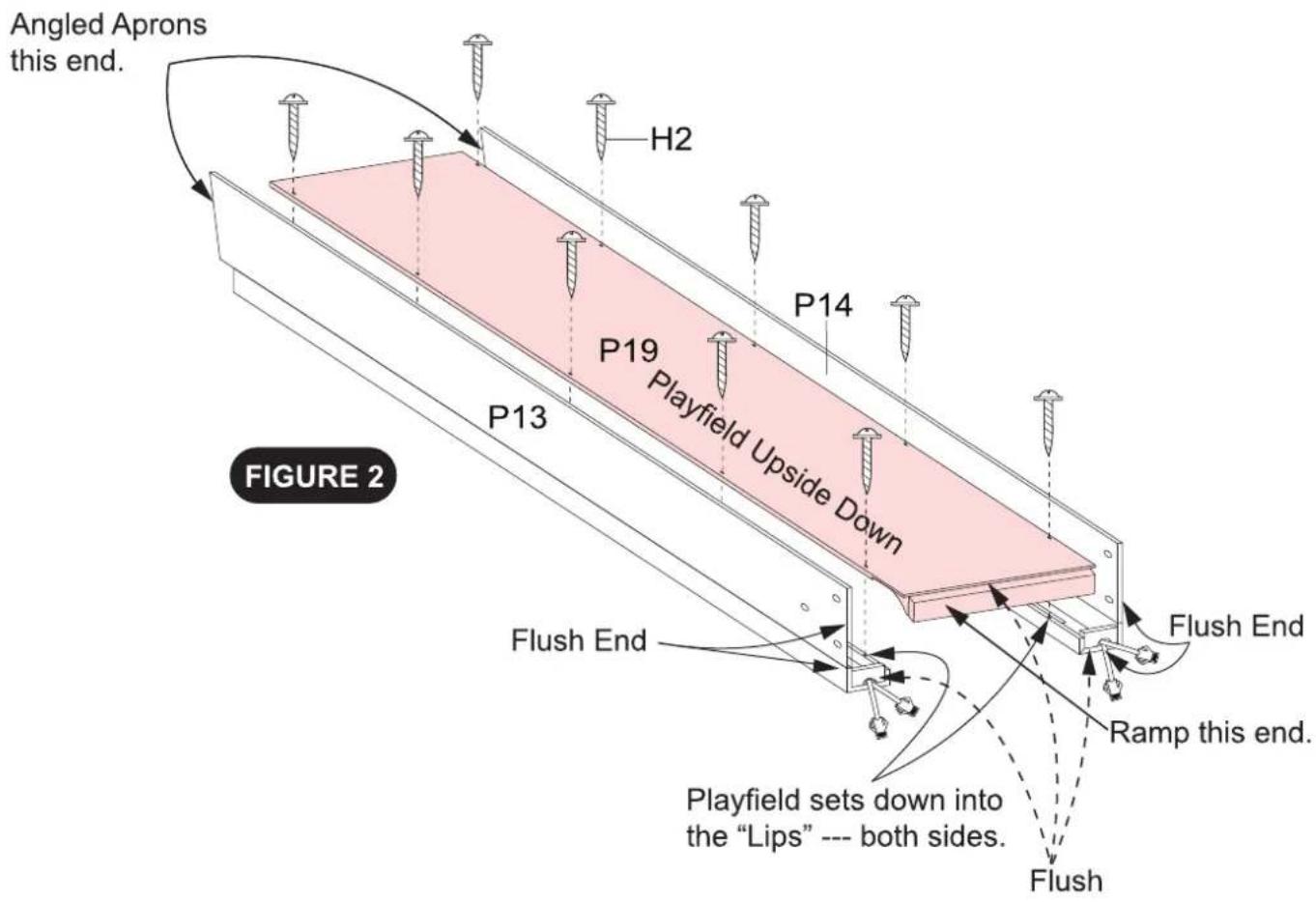
Attach the P19 Playfield onto the STEP 1 Assemblies using the pilot holes and the H2 Philips Round Screws as shown in FIGURE 2.
Tighten, but DO NOT strip out H2 screws.
text_image
Angled Aprons this end. H2 P14 P19 Playfield Upside Down P13 Flush End Flush End Ramp this end. Playfield sets down into the "Lips" --- both sides. Flush FIGURE 2Assembly Note: During assembly, correct orientation of all parts is critical for correct assembly. Please study all diagrams closely.
PARTS REQUIRED
1pc - P1 End Apron
1pc - P2 Left Front Leg
1pc - P3 Right Front Leg
1pc - P17 Left Leg
1pc - P18 Right Leg
4pcs - H2 Phillips Round Head Screw
20pcs - H3 Phillips Round Head Screw
6pcs - P23 Metal Connection Plate
STEP 3
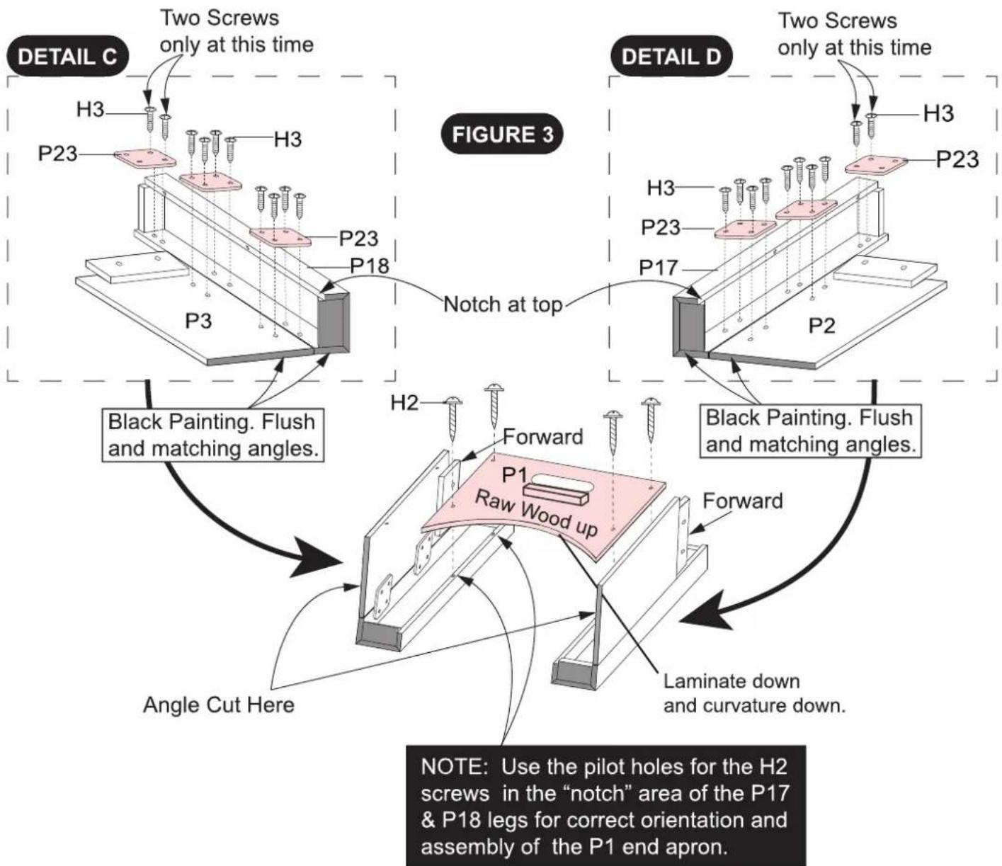
Attach the P3 Right Front Leg onto the P18 Right Leg using the P23 Metal Connection Plates, the pilot holes and the H3 Phillips Round Head Screws as shown in DETAIL C.
Attach the P2 Left Front Leg onto the P17 Left Leg using the P23 Metal Connection Plates, the pilot holes and the H3 Phillips Round Head Screws as shown in DETAIL D.
Attach the DETAIL C / D Assemblies onto the P1 End Apron using the pilot holes and the H2 Phillips Round Head Screws as shown in FIGURE 3.
Tighten, but DO NOT strip out H2,H3 screws.
text_image
DETAIL C Two Screws only at this time H3 P23 H3 P23 P18 P3 NOTCH at top Black Painting. Flush and matching angles. FIGURE 3 DETAIL D Two Screws only at this time H3 P23 H3 P23 P17 Notch at top Black Painting. Flush and matching angles. Forward P1 Raw Wood up Forward Laminate down and curvature down. Angle Cut Here NOTE: Use the pilot holes for the H2 screws in the "notch" area of the P17 & P18 legs for correct orientation and assembly of the P1 end apron.PARTS REQUIRED
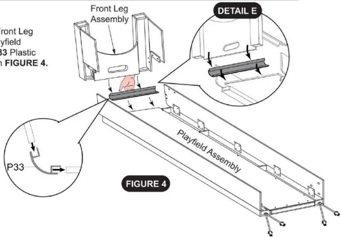
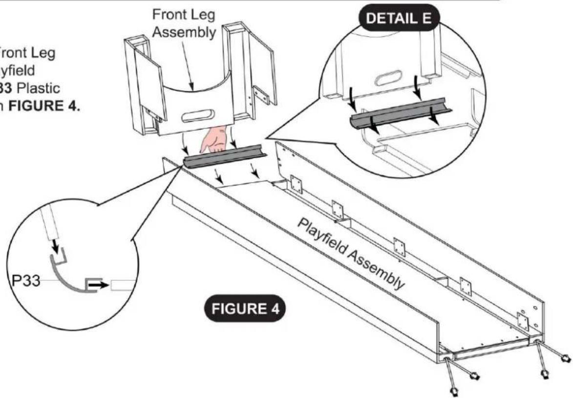
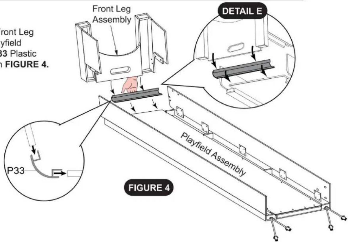
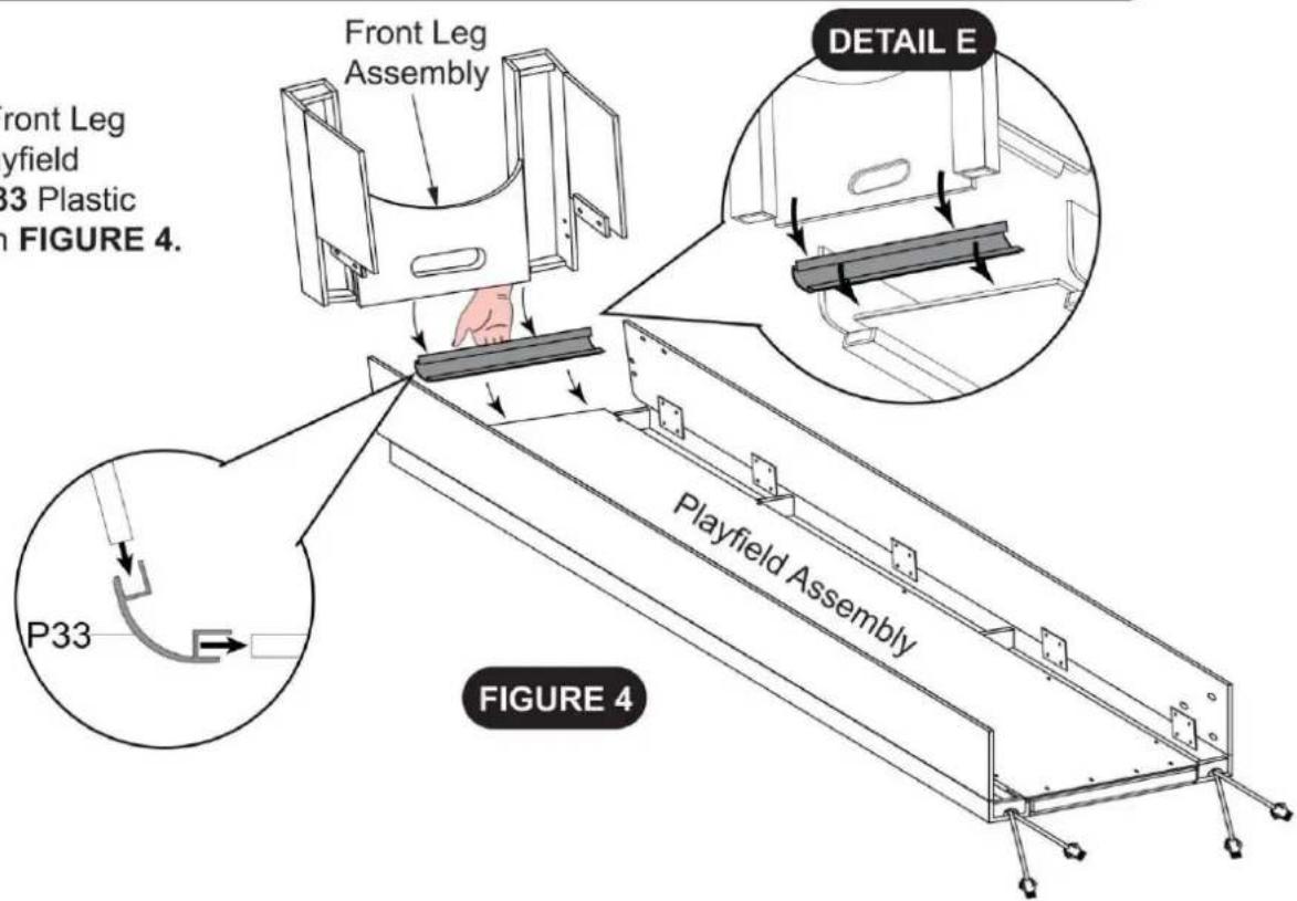
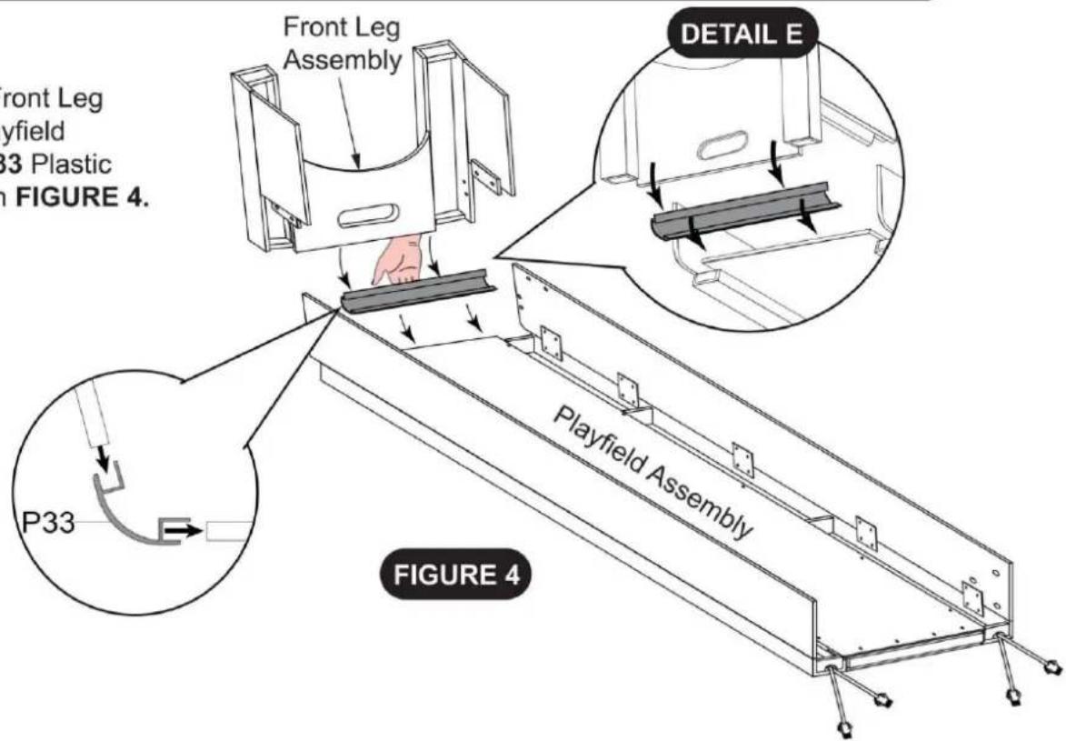
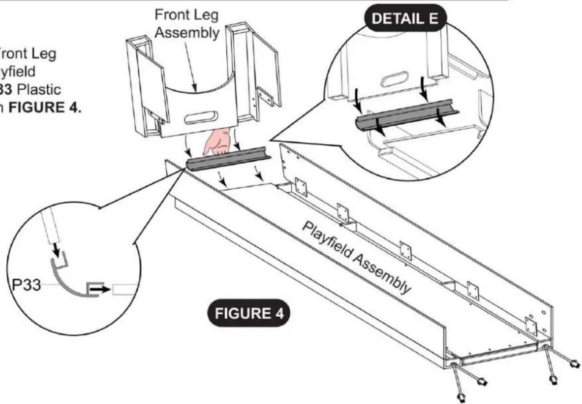
1pc - P33 Plastic Connector (Playfield to Front Leg)
STEP 4
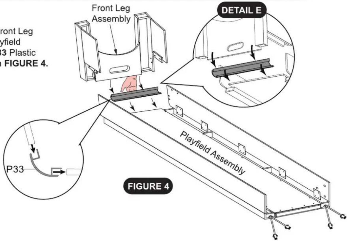
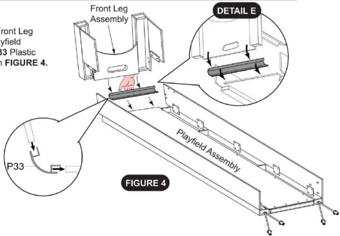
Connect the STEP 3 Front Leg Assembly onto the Playfield Assembly using the P33 Plastic Connector as shown in FIGURE 4.
text_image
Front Leg Assembly PART 3 Plastic FIGURE 4. P33 Playfield Assembly DETAIL E FIGURE 4PARTS REQUIRED
4pcs - H1 Phillips Round Head Screw
4pcs - H3 Phillips Round Head Screw
STEP 5
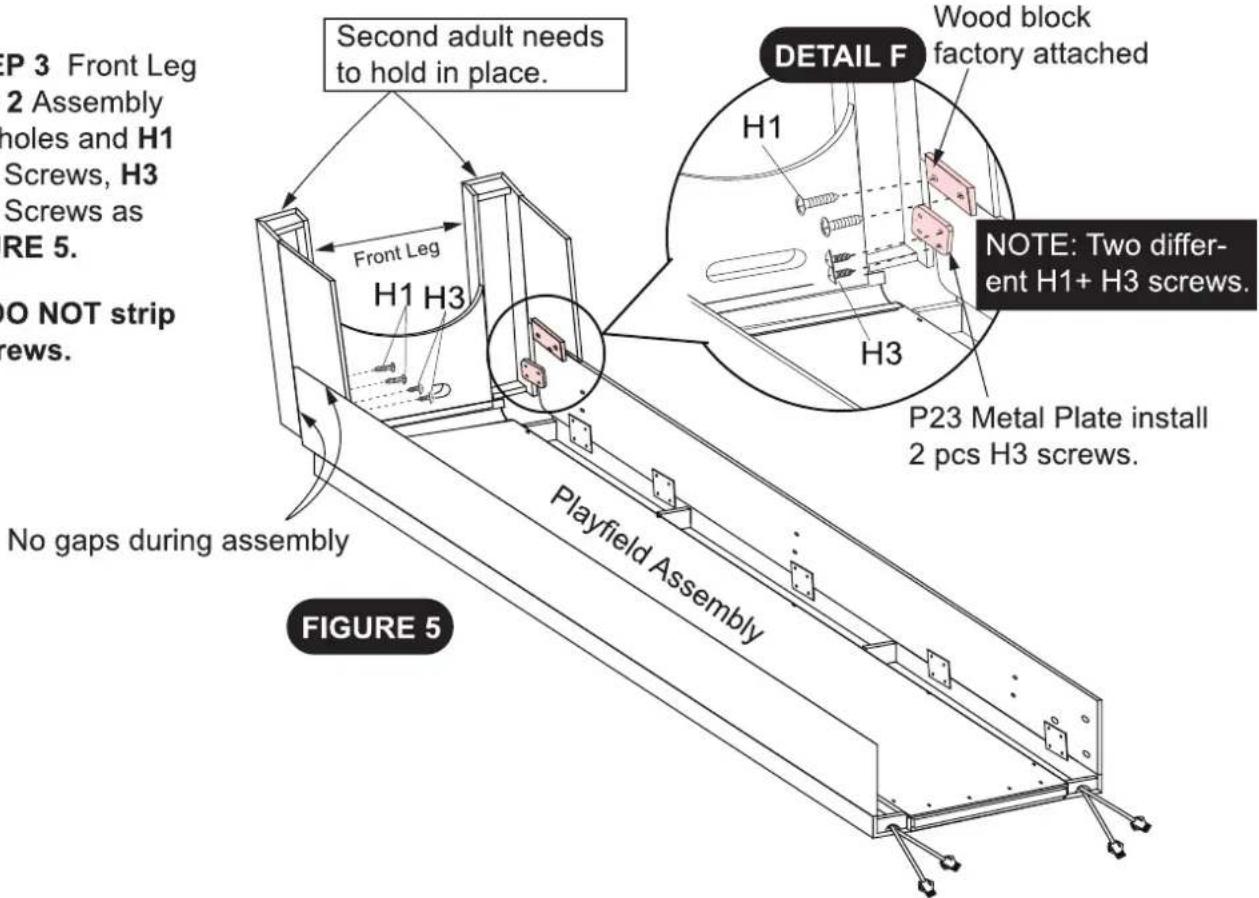
Attach the STEP 3 Front Leg onto the STEP 2 Assembly using the pilot holes and H1 Phillips Round Screws, H3 Phillips Round Screws as shown in FIGURE 5.
Tighten, but DO NOT strip out H1, H3 screws.
text_image
EP 3 Front Leg 2 Assembly holes and H1 Screws, H3 Screws as RE 5. NO NOT strip rews. Second adult needs to hold in place. DETAIL F Wood block factory attached H1 H3 NOTE: Two differ- ent H1+ H3 screws. P23 Metal Plate install 2 pcs H3 screws. No gaps during assembly Playfield Assembly FIGURE 5PARTS REQUIRED
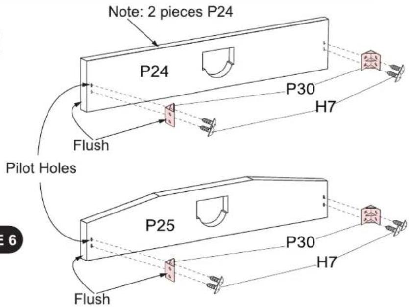
2pcs - P24 Middle Support Board
1pc - P25 End Support Board
6pcs - P30 Black Plastic "L" Bracket
12pcs -H7 Phillips Round Head Screw
STEP 6
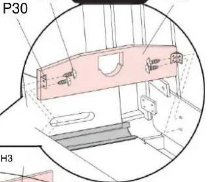
Attach the P30 Plastic "L" Brackets onto the P24 / P25 Support Boards using the pilot holes and the H7 Phillips Round Screws as shown in FIGURE 6.
Tighten, but DO NOT strip out H3 screws.
text_image
Note: 2 pieces P24 P24 P30 H7 Flush Pilot Holes P25 P30 H7 FlushPARTS REQUIRED
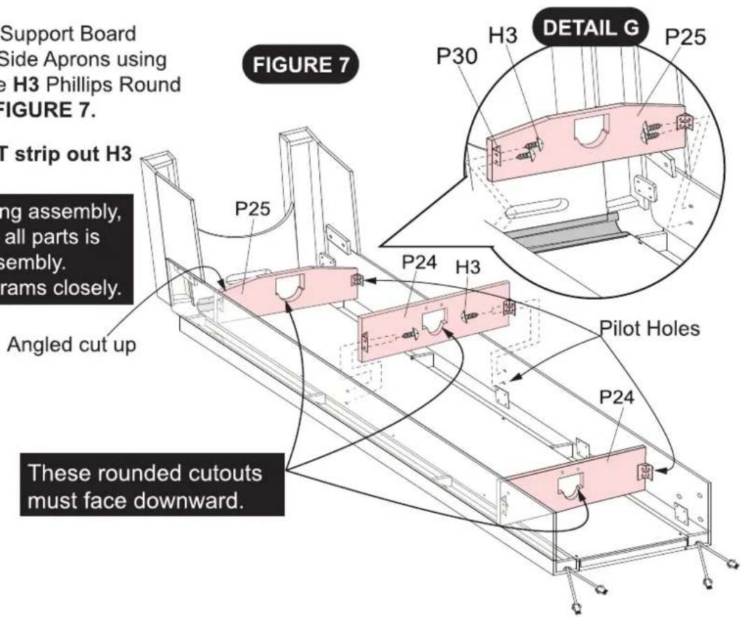
12pcs - H3 Phillips Round Head Screw
STEP 7
Attach the P24 / P25 Support Board Assemblies onto the Side Aprons using the pilot holes and the H3 Phillips Round Screws as shown in FIGURE 7.
Tighten, but DO NOT strip out H3 screws.
Assembly Note: During assembly, correct orientation of all parts is critical for correct assembly. Please study all diagrams closely.
text_image
Support Board Side Aprons using e H3 Phillips Round FIGURE 7. T strip out H3 ing assembly, all parts is sembly. rams closely. Angled cut up P25 P24 H3 P30 DETAIL G P25 P24 Pilot Holes P24 These rounded cutouts must face downward.PARTS REQUIRED
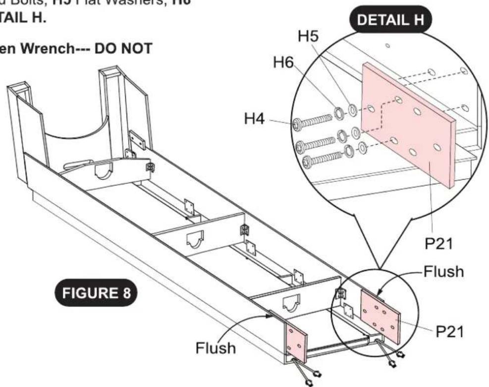
2pcs - P21 Connecting Board
6pcs - H5 Flat Washer
6pcs - H4 Allen Head Bolt
6pcs - H6 Lock Washer
STEP 8
Attach the P21 Connecting Boards onto the inside of the Side Aprons using the H4 Allen Head Bolts, H5 Flat Washers, H6 Lock Washers as shown in DETAIL H.
Tighten H4 bolts using T1 Allen Wrench--- DO NOT overtighten.
text_image
PHIL Wrench--- DO NOT DETAIL H H5 H6 H4 P21 Flush P21 FIGURE 8PARTS REQUIRED
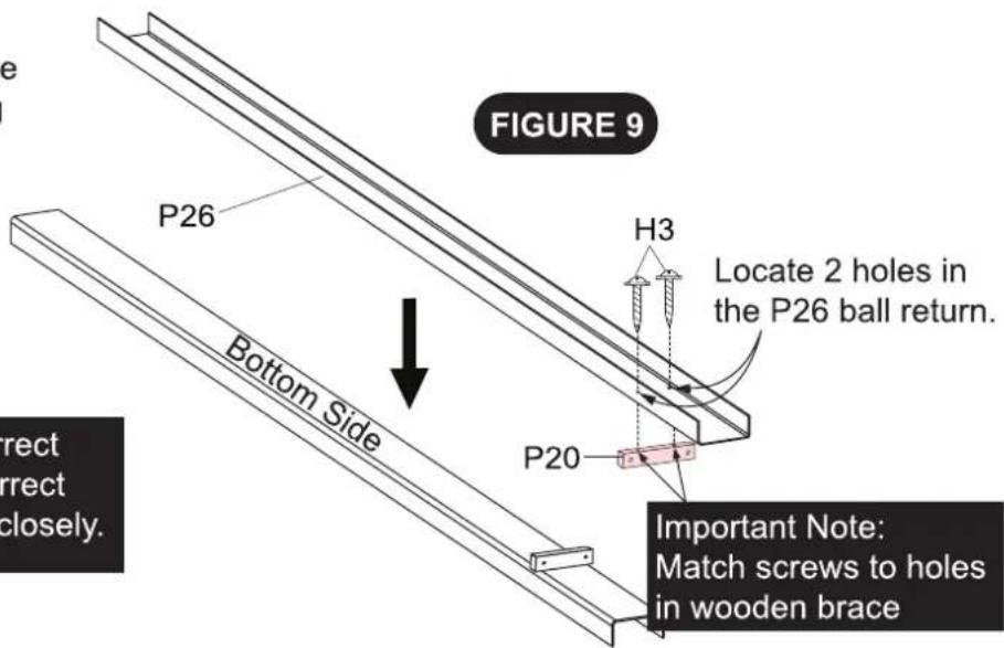
1pc - P20 Wooden Support Brace
2pcs - H3 Phillips Round Head Screw
1pc - P26 Plastic Ball Return
STEP 9
Attach the P20 Wooden Support Brace onto the P26 Plastic Ball Return using the H3 Philips Round Screws as shown in FIGURE 9.
Tighten, but DO NOT strip out H3 screws.
Assembly Note: During assembly, correct orientation of all parts is critical for correct assembly. Please study all diagrams closely.
text_image
FIGURE 9 P26 H3 Locate 2 holes in the P26 ball return. Bottom Side P20 Important Note: Match screws to holes in wooden brace rect rect closely.PARTS REQUIRED
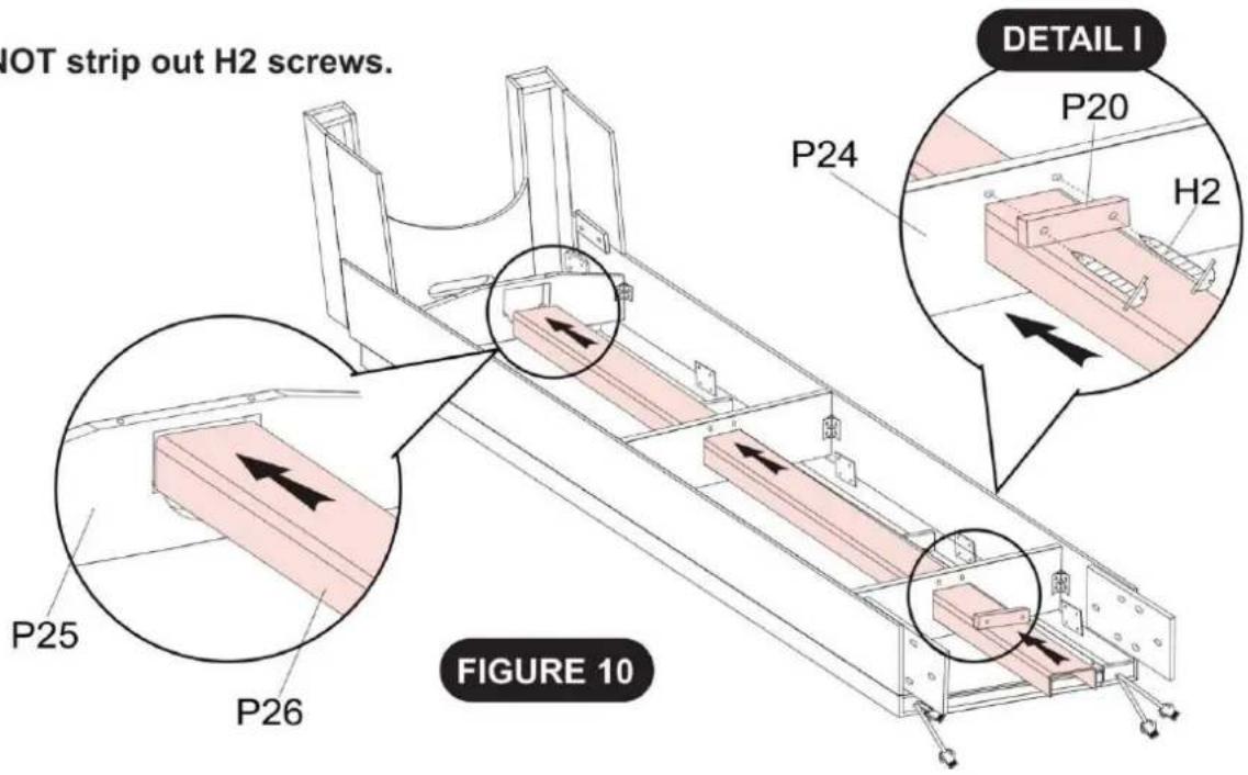
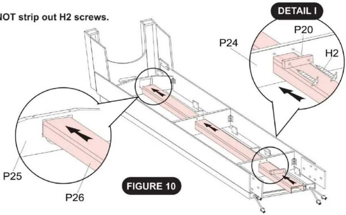
2pcs - H2 Phillips Round Head Screw
STEP 10
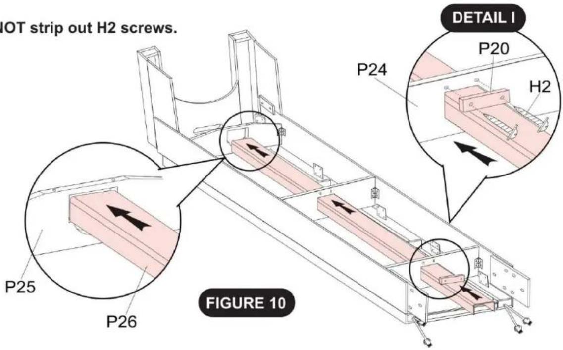
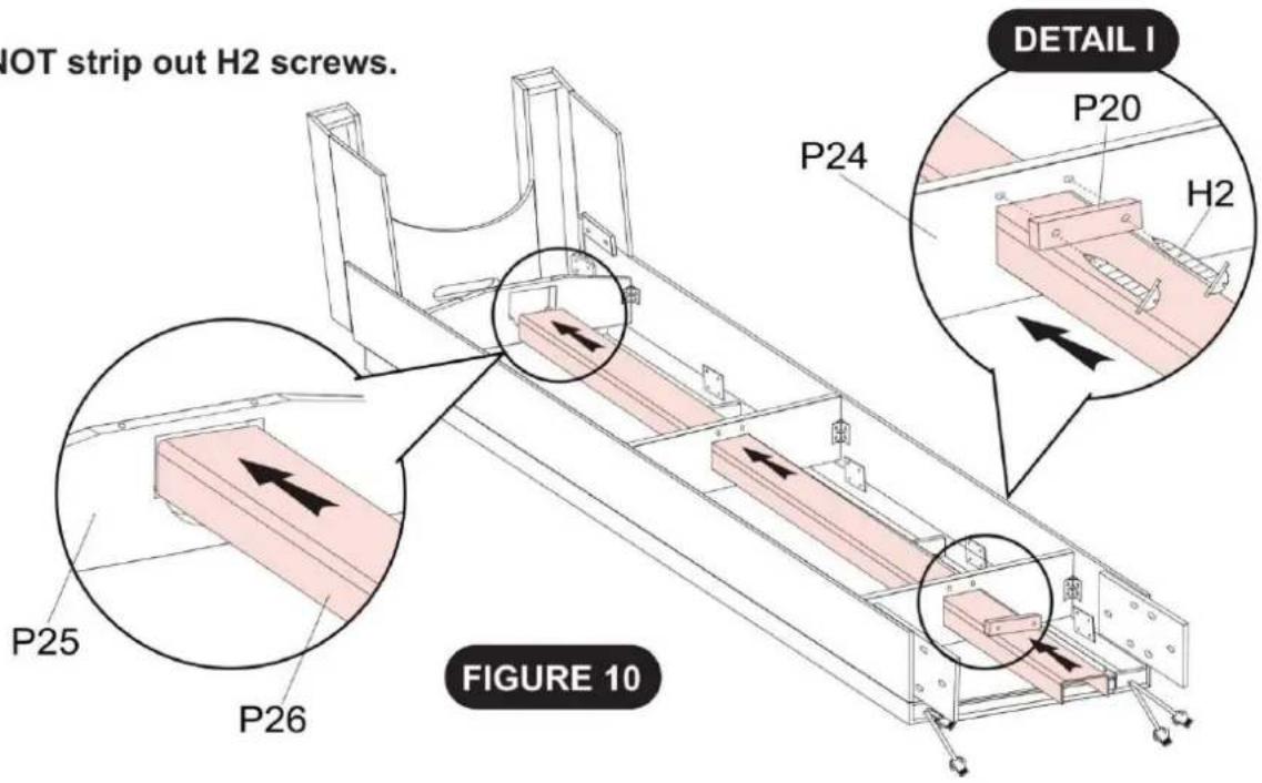
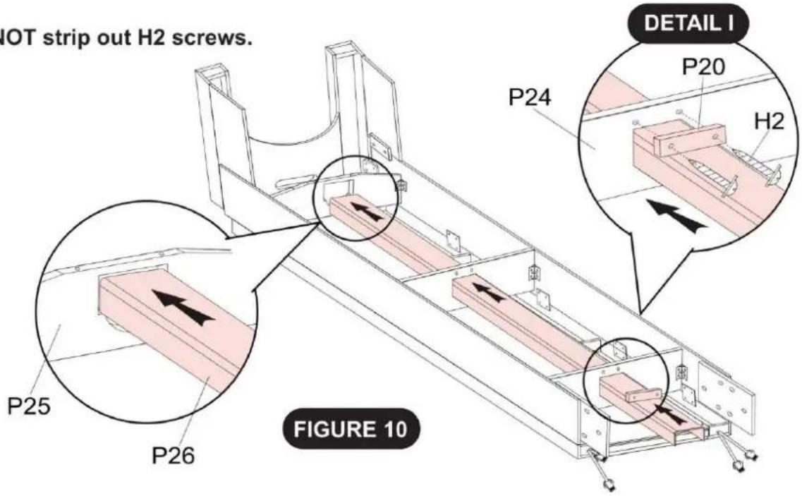
Install and attach the P26 Plastic Ball Return onto the P24/25 Support Boards using the H2 Philips Round Screws as shown in DETAIL I.
Tighten, but DO NOT strip out H2 screws.
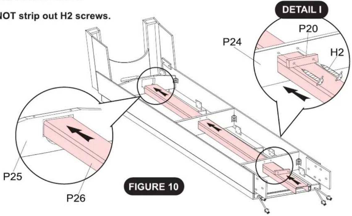
text_image
IOT strip out H2 screws. P24 DETAIL I P20 H2 P25 P26 FIGURE 10PARTS REQUIRED
1pc - P22 Goal Box Bottom Board
4pcs - H2 Phillips Round Head Screw
NOTE: NEED 2 ADULTS FOR ASSEMBLY
STEP 11
Attach the P22 Goal Box Bottom Board onto the P25 End Support Board using the H2 Philips Round Screws as shown in DETAIL J.
Tighten, but DO NOT strip out H2 screws.
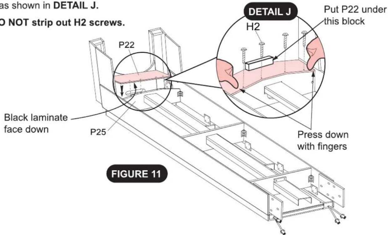
text_image
as shown in DETAIL J. DO NOT strip out H2 screws. P22 DETAIL J H2 Put P22 under this block Black laminate face down P25 Press down with fingers FIGURE 11PARTS REQUIRED
1pc - P7 Right Back Leg
1pc - P8 Left Back Leg
1pc - P28 Back Board - D
4pcs - H2 Phillips Round Head Screw
NOTE: NEED 2 ADULTS FOR ASSEMBLY
STEP 12
Attach the P28 Lower Front Cabinet Board onto the P7 / P8 Back Legs using the pilot holes and the H2 Phillips Round Screws as shown in FIGURE 12.
Tighten, but DO NOT strip out H2 screws.
Second adult holds here
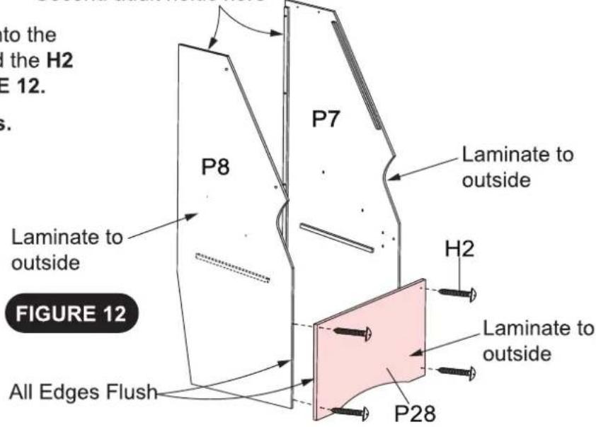
text_image
to the the H2 E 12. s. P7 P8 Laminate to outside Laminate to outside H2 Laminate to outside All Edges Flush P28 FIGURE 12PARTS REQUIRED
6pcs - H4 Allen Head Bolt
6pcs - H5 Flat Washer
6pcs - H6 Lock Washer
NOTE: NEED 2 ADULTS FOR ASSEMBLY
STEP 13
Attach the STEP 12 Assembly onto the STEP 11 Assembly using the H4 Allen Head Bolts, H5 Flat Washers, H6 Lock Washers as shown in FIGURE 13.
Tighten all H4 Bolts using the T1 Allen Wrench--- DO NOT overtigten.
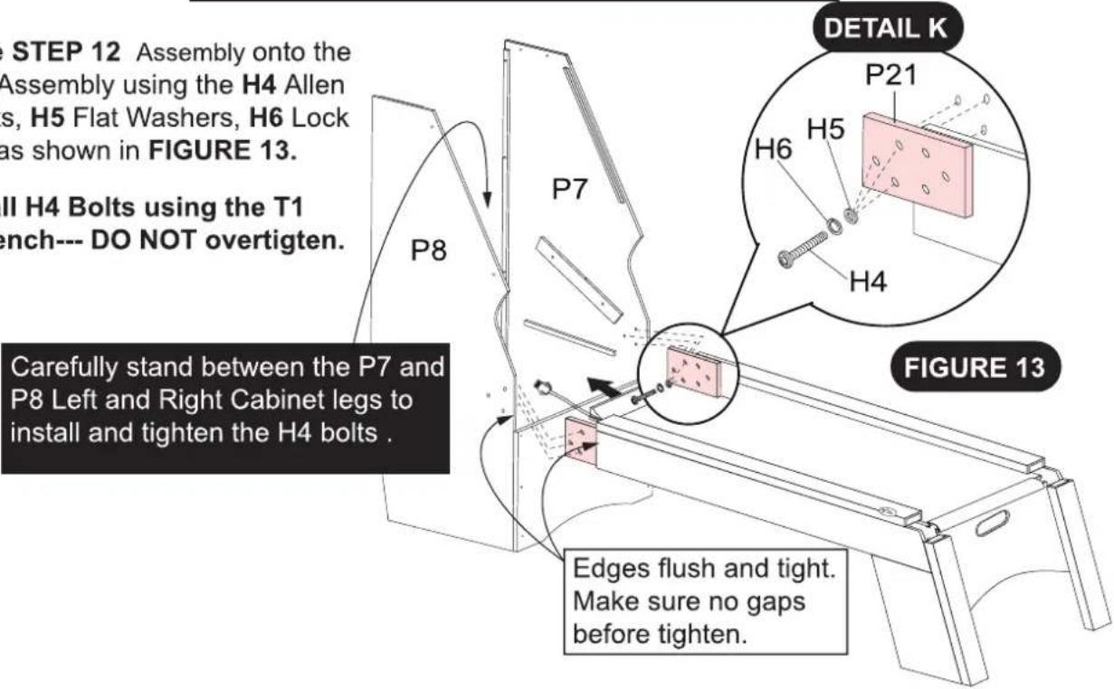
text_image
e STEP 12 Assembly onto the Assembly using the H4 Allen s, H5 Flat Washers, H6 Lock as shown in FIGURE 13. II H4 Bolts using the T1 ench--- DO NOT overtigten. P8 P7 DETAIL K P21 H5 H6 H4 Carefully stand between the P7 and P8 Left and Right Cabinet legs to install and tighten the H4 bolts . FIGURE 13 Edges flush and tight. Make sure no gaps before tighten.Carefully stand between the P7 and P8 Left and Right Cabinet legs to install and tighten the H4 bolts.
PARTS REQUIRED
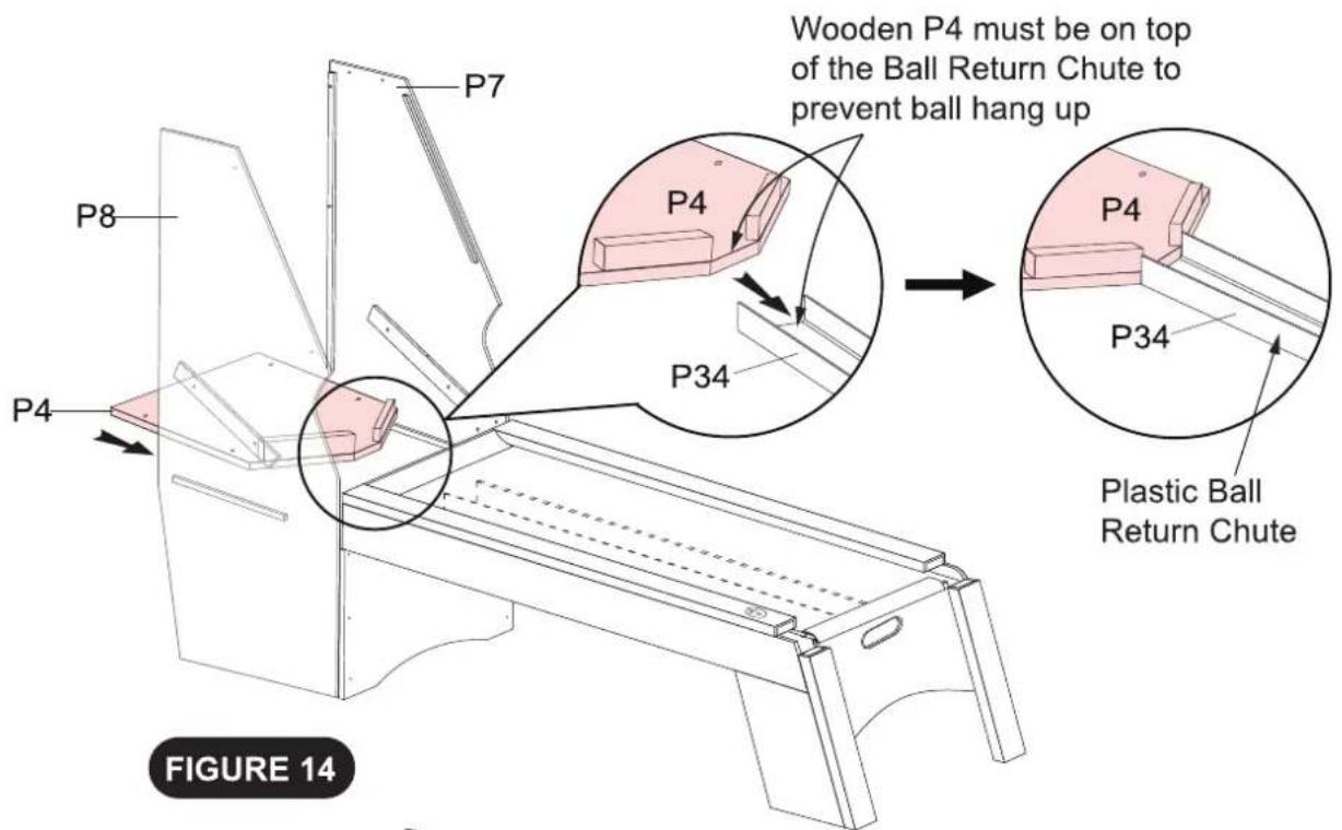
1pc - P4 Ball Stop Bottom Board
4pcs - H1 Phillips Round Head Screw
STEP 14
Attach the P4 Ball Stop Bottom Board onto the P7 / P8 Back Legs using pilot holes and the H1 Phillips Round Screws as shown in FIGURE 14.
Tighten, but DO NOT strip out H1 screws.
text_image
Wooden P4 must be on top of the Ball Return Chute to prevent ball hang up P4 P34 P7 P8 P4 P34 Plastic Ball Return Chute FIGURE 14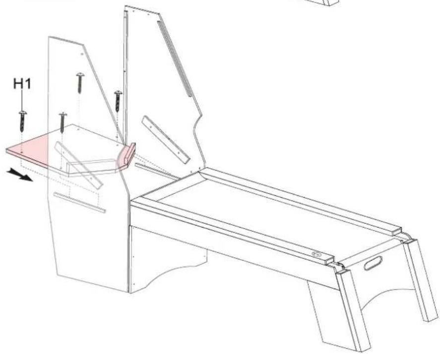
natural_image
Technical line drawing of a mechanical assembly with labeled component H1 (no text or symbols beyond label)PARTS REQUIRED
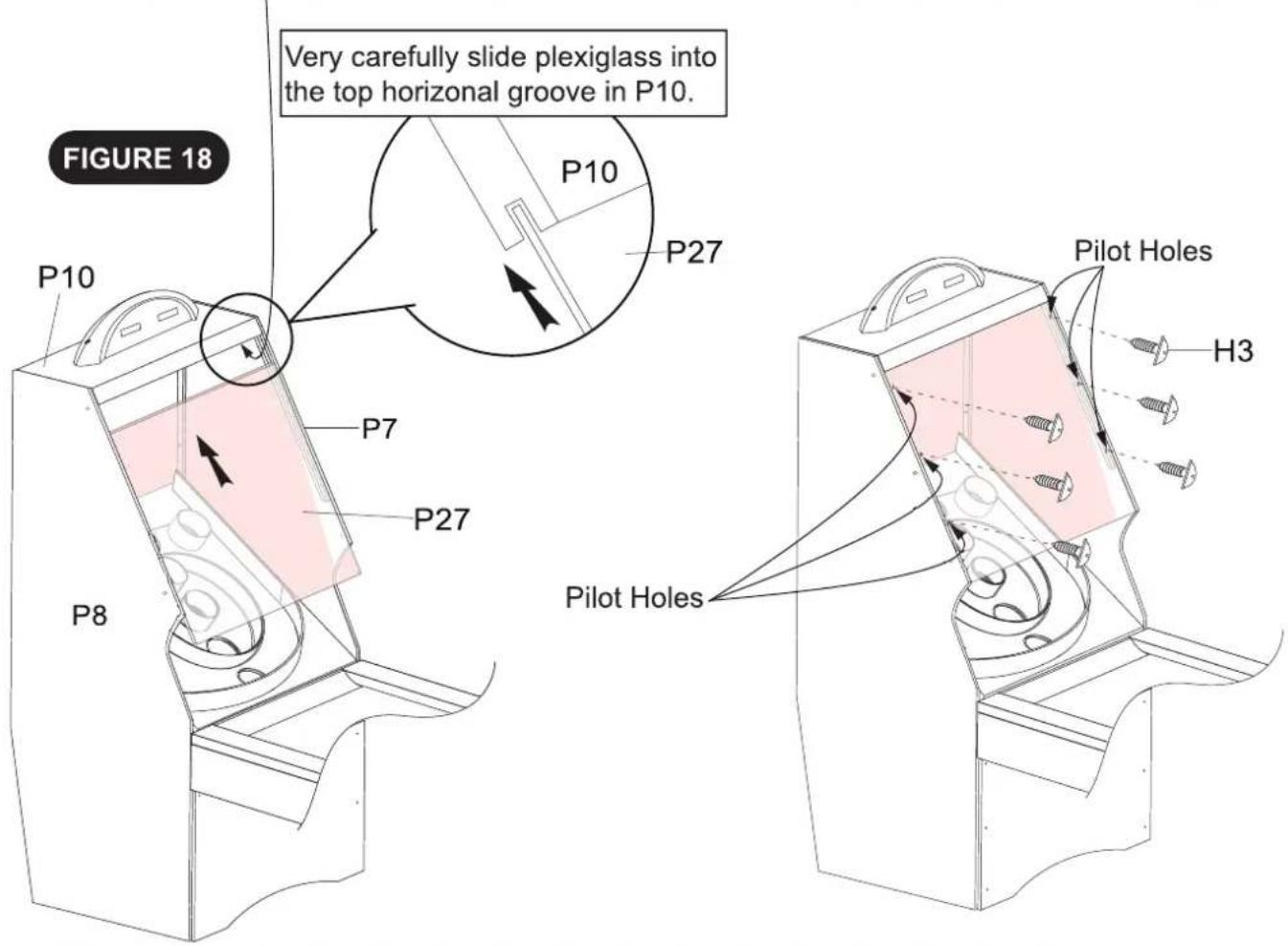
1pc - P27 Clear Plexiglass
6pcs - H3 Phillips Round Head Screw
STEP 18
Install the P27 Clear Plexiglass onto the P7 / P8 Back Legs and attach onto the P10 Top Cabinet Panel using pilot holes and the H3 Phillips Round Screws as shown in FIGURE 18.
Tighten, but DO NOT overtighten H3 Screws as this could crack the plexiglass.
NOTE:
The groove for the top of the P27 plexiglass is in the lower front side of the P10 top cabinet panel. If the plexiglass will not easily slip into this groove, it will be necessary to loosen the 4 pcs H4 bolts that hold the P10 top cabinet panel and carefully tap or push it forward thus moving the groove forward just enough to allow the P27 plexiglass to slip into the groove.
text_image
FIGURE 18 P10 P10 P27 Very carefully slide plexiglass into the top horizontal groove in P10. P7 P27 P8 Pilot Holes H3 Pilot HolesNOTE:
Carefully remove protective covering from the plexiglass before installation, avoid finger prints on the plexiglass by wearing cotton gloves.
PARTS REQUIRED
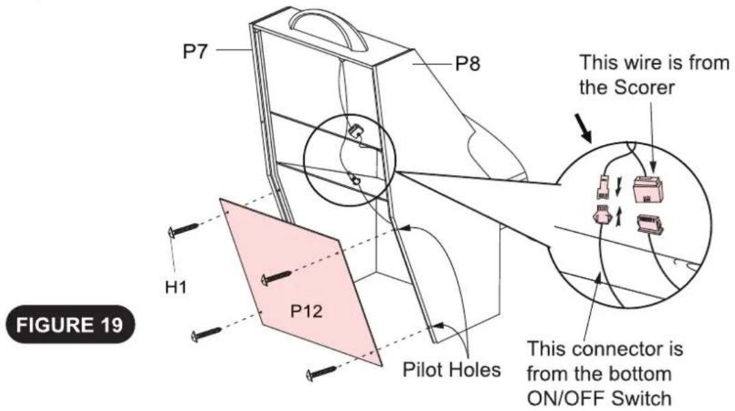
1pc - P12 Lower Back Cabinet Board
4pcs - H1 Phillips Round Head Screw
STEP 19
Attach the P12 Lower Back Cabinet Board onto the P7 / P8 Back Legs using pilot holes and the H1 Phillips Round Screws as shown in FIGURE 19.
NOTE: All male/ female connectors must be turned correctly in order to plug into each other.
Tighten, but DO NOT strip out H1 Screws.
text_image
P7 P8 This wire is from the Scorer H1 P12 Pilot Holes This connector is from the bottom ON/OFF Switch FIGURE 19PARTS REQUIRED
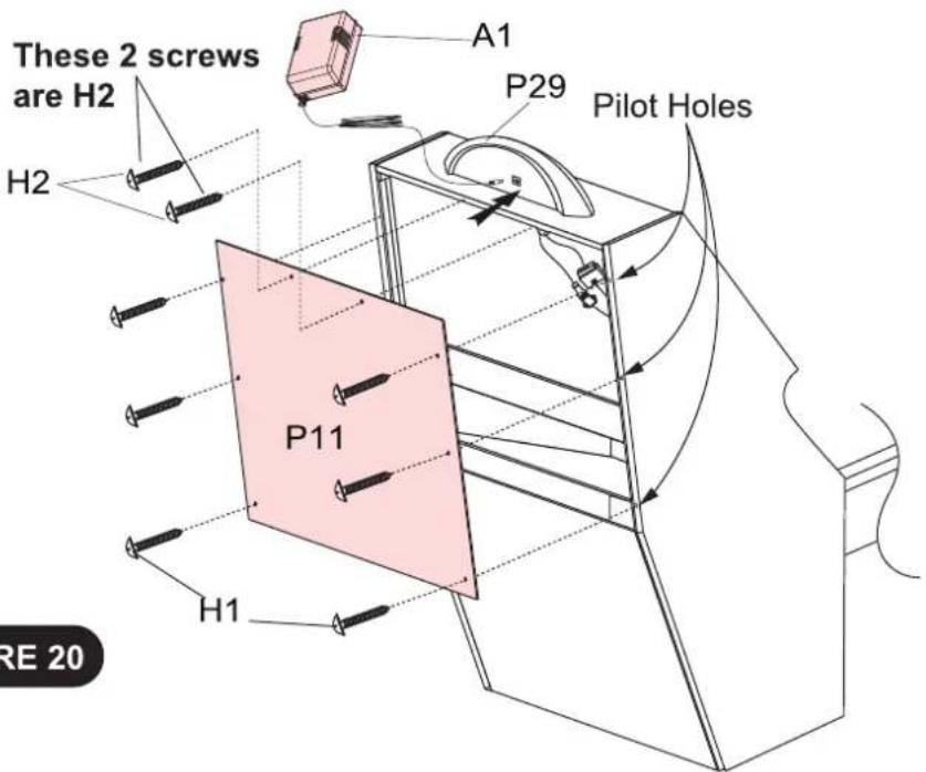
1pc - P11 Upper Back Cabinet Board
6pcs - H1 Phillips Round Head Screw
1pc - A1 A/C Adapter
2pcs - H2 Phillips Round Head Screw
STEP 20
Attach the P11 Upper Back Cabinet Board onto the Back Leg Cabinet using pilot holes and the H1 and H2 Phillips Round Screws as shown in FIGURE 20.
Tighten, but DO NOT strip out H1, H3 Screws.
Plug A1 A/C Adapter into back side of P29 Electronic Scorer
Do not allow A/C Adapter cord to be a trip hazard.
text_image
These 2 screws are H2 H2 A1 P29 Pilot Holes P11 H1 RE 20FIGURE 20
PARTS REQUIRED
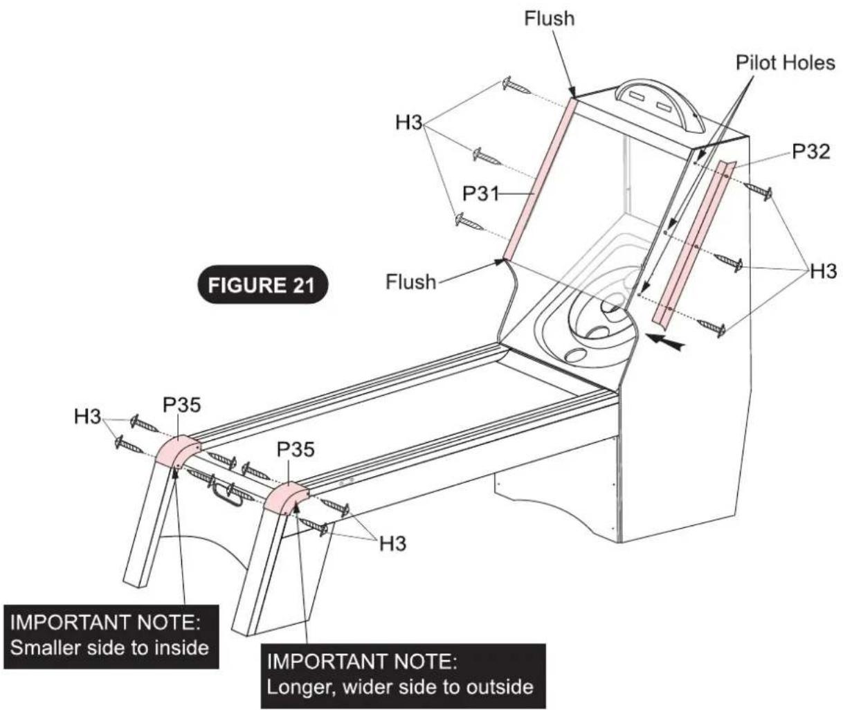
1pc - P31 Left Plastic Trim Strip
14pcs - H3 Phillips Round Head Screw
1pc - P32 Right Plastic Trim Strip
2pcs - P35 Top Rail Plastic Corner Cap
STEP 21
Attach the P31 / 32 Plastic Trim Strips onto the Cabinet using pilot holes and the H3 Phillips Round Screws as shown in FIGURE 21.
Attach the P35 Top Rail Plastic Corner Caps onto the Front Legs using pilot holes and the H3 Phillips Round Screws as shown in FIGURE 21.
Tighten, but DO NOT strip out H3 Screws.
text_image
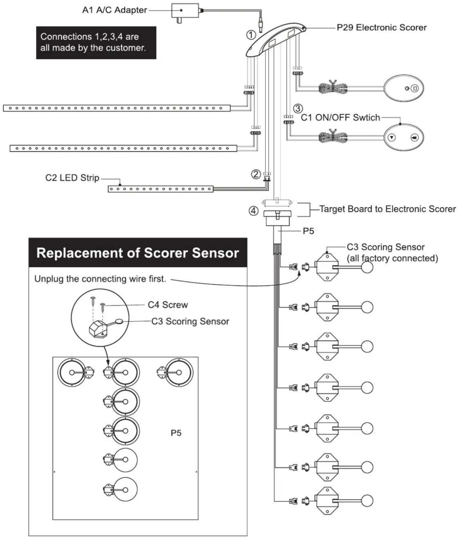
Flush H3 P31 Pilot Holes H3 Flush H3 P35 P35 H3 IMPORTANT NOTE: Smaller side to inside IMPORTANT NOTE: Longer, wider side to outside FIGURE 21ELECTRONIC CONNECTIONS
NOTE: All male/ female connectors must be turned correctly in order to plug into each other.
text_image
A1 A/C Adapter Connections 1,2,3,4 are all made by the customer. P29 Electronic Scorer C1 ON/OFF Switch C2 LED Strip Target Board to Electronic Scorer P5 C3 Scoring Sensor (all factory connected) Replacement of Scorer Sensor Unplug the connecting wire first. C4 Screw C3 Scoring Sensor P5Congratulations! You have now assembled your game table. Please note the Care and Use instructions below to ensure many years of trouble-free use of your game table.
ELBATRUOYFOESUDN
- Use spray furniture polish to clean all exterior surfaces of your game table and on the playfield (but not the plexiglass which requires an acrylic cleaner/polish).
- Use only a suitable UK AC household outlet, and ensure the cord is not a trip hazard.
- This product is intended for INDOOR use only.
- DO NOT sit, climb or lean on the table.
- DO NOT drag the table when moving it. This will damage the legs.
- DO NOT set drinks on the table.
PRODUCT PARTS LIST FOR MODEL
188805
| Key # | Part # | Description | Qty. |
| H1 | 188805HLH1 | 3.5 mm x 18 mm Phillips Round Head Screw 24 | |
| H2 | 188805HLH2 | 3.5 mm x 28 mm Phillips Round Head Screw | 28 |
| H3 | 188805HLH3 | 3.5 mm x 12 mm Phillips Round Head Screw | 98 |
| H4 | 188805HLH4 | 6 mm x 25 mm Allen Head Bolt | 16 |
| H5 | 188805HLH5 | 6.5 mm x 18 mm Flat Washer | 16 |
| H6 | 188805HLH6 | M6 Lock Washer | 16 |
| H7 | 188805HLH7 | 123.5 mm x 14 mm | |
| T1 | 188805HLT1 | M5 Allen Wrench | 1 |
| P1 | 188805HLP1 | Front Leg Apron | 1 |
| P2 | 188805HLP2 | Left Front Leg | 1 |
| P3 | 188805HLP3 | Right Front Leg | 1 |
| P4 | 188805HLP4 | Ball Stop Bottom Board | 1 |
| P5 | 188805HLP5 | Target Board with Scoring Sensors | 1 |
| P6 | 188805HLP6 | Top Rail Plastic Corner Cap | 2 |
| P7 | 188805HLP7 | Right Back Cabinet Leg | 1 |
| P8 | 188805HLP8 | Left Back Cabinet Leg | 1 |
| P9 | 188805HLP9 | Backboard with Graphic | 1 |
| P10 | 188805HLP10 | Top Cabinet Panel for Scorer | 1 |
| P11 | 188805HLP11 | Upper Back Cabinet Board | 1 |
| P12 | 188805HLP12 | Lower Back Cabinet Board | 1 |
| P13 | 188805HLP13 | Left Side Apron | 1 |
| P14 | 188805HLP14 | Right Side Apron | 1 |
| P15 | 188805HLP15 | Left Top Rail with Control Switch and Wiring | 1 |
| P16 | 188805HLP16 | Right Top Rail | 1 |
| P17 | 188805HLP17 | Left Leg (assembled with P2) | 1 |
| P18 | 188805HLP18 | Right Leg (assembled with P3) | 1 |
| P19 | 188805HLP19 | Playfield with End Ramp | 1 |
| P20 | 188805HLP20 | Wooden Support Brace (packed with P30) | 1 |
| P21 | 188805HLP21 | Connecting Board | 2 |
| P22 | 188805HLP22 | Goal Box Bottom Board | 1 |
| P23 | 188805HLP23 | Metal Connection Plate | 16 |
| P24 | 188805HLP24 | Middle Support Board | 2 |
| P25 | 188805HLP25 | End Support Board | 1 |
| P26 | 188805HLP26 | Plastic Ball Return | 2 |
| P27 | 188805HLP27 | Clear Plexiglass | 1 |
| P28 | 188805HLP28 | Lower Front Cabinet Board | 1 |
| P29 | 188805HLP29 | Electronic Scorer | 1 |
| Key # Part # | Description | Qty. |
| P30 188805HLP30 | Black Plastic “L” Bracket 6 | |
| P31 188805HLP31 | Left Plastic Trim Strip | 1 |
| P32 188805HLP32 | Right Plastic Trim Strip | 1 |
| P33 188805HLP33 | Plastic Connector (Playfield to Front Leg) | 1 |
| A1 188805HLA1 | A/C Adapter | 1 |
| A2 188805HLA2 | Ball | 4 |
| C1 188805HLC1 | ON / OFF Switch | 1 |
| C2 188805HLC2 | Led Strip | 2 |
| C3 188805HLC3 | Scoring Sensor | 7 |
| C4 188805HLC4 | 3.5mm x 12mm Phillips Round Head Screw | 14 |
| K1 188805HLK1 | Hardware Kit | 1 |
| M1 188805-HLM1 | Instruction Manual | 1 |
VEVOR®
TOUGH TOOLS, HALF PRICE
Technical Support and E-Warranty Certificate www.vevor.com/support
Machine Translated by Google
text_image
11-1/2" 18-1/4"text_image
23-1/2" 26-1/4"text_image
58" 17-34"text_image
58" 17-3/4"text_image
23-1/4" 16-1/2"text_image
80-1/2" CM 7-1text_image
80-1/2" 7-1/2"text_image
3-1/2" 78-3/8"text_image
3-1/2" 78-3/8"text_image
17-3/8" 3-1/2" Black Painting 18-1/4" 79-1/4"Machine Translated by Google
text_image
Angled Aprons this end. H2 P14 P19 Playfield Upside Down P13 Flush End Flush End Ramp this end. Playfield sets down into the "Lips" --- both sides. Flush FIGURE 21pc - P33 Plastic Connector (Playfield to Front Leg)
STEP 4
Connect the STEP 3 Front Leg Assembly onto the Playfield Assembly using the P33 Plastic Connector as shown in FIGURE 4.
text_image
Front Leg byfield B3 Plastic Figure 4. Front Leg Assembly DETAIL E Playfield Assembly P33 FIGURE 4PIÈCES REQUISES
Tighten, but DO NOT strip out H2 screws.

text_image
NOT strip out H2 screws. P24 DETAIL 1 P20 H2 P25 P26 FIGURE 10PIÈCES REQUISES
text_image
P7 P8 This wire is from the Scorer H1 P12 Pilot Holes This connector is from the bottom Interrupteur marche/arrêt FIGURE 19PIÈCES REQUISES
text_image
Flush H3 P31 P32 H3 Flush Pilot Holes H3 P35 H3 P35 H3 IMPORTANT NOTE: Smaller side to inside IMPORTANT NOTE: Longer, wider side to outside FIGURE 21CONNEXIONS ÉLECTRONIQUES
Machine Translated by Google
T1 -M6 Inbusschlüssel
(1 Stk.)
TEILEKENNZEICHNUNG
text_image
11-1/2" 18-1/4"text_image
23-1/2" 26-1/4"text_image
58" 17-3/4"P7 – Rechter Verteidiger Schrankbein (1 Stk.)
text_image
58" 17-3/4"P8 – Linksverteidiger Schrankbein (1 Stk.)
text_image
23-1/4" 16-1/2"text_image
80-1/2" 7-1"text_image
80-1/2" 7-1/2"text_image
3-1/2" 78-3/8"text_image
3-1/2" 78-3/8"text_image
17-3/8" 3-1/2" Black Painting 18-1/4" 79-1/4"text_image
Angled Aprons this end. H2 P14 P19 Playfield Upside Down P13 Flush End Flush End Playfield sets down into the "Lips" --- both sides. Ramp this end. Spülen FIGURE 21pc - P33 Plastic Connector (Playfield to Front Leg)
STEP 4
Connect the STEP 3 Front Leg Assembly onto the Playfield Assembly using the P33 Plastic Connector as shown in FIGURE 4.
text_image
Front Leg byfield 3 Plastic Figure 4. Front Leg Assembly DETAIL E Playfield Assembly P33 FIGURE 4BENÖTIGTE TEILE
Tighten, but DO NOT strip out H2 screws.
text_image
NOT strip out H2 screws. P24 DETAIL 1 P20 H2 P25 P26 FIGURE 10BENÖTIGTE TEILE
natural_image
Technical line drawing of a mechanical device with labeled component H1, showing internal components and mounting brackets (no text or symbols beyond label)text_image
Flush H3 P31 P32 H3 Flush Pilot Holes H3 P35 H3 P35 H3 IMPORTANT NOTE: Smaller side to inside IMPORTANT NOTE: Longer, wider side to outside FIGURE 21Machine Translated by Google
text_image
11-1/2" 18-1/4"P1 - Grembiule per la gamba
anteriore (1 pz)
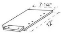
P2 - Gamba anteriore
sinistra (si monta con P17) (1 pz)
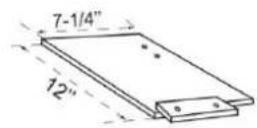
P3 - Gamba anteriore destra
(si monta con P18) (1 pz)
text_image
23-1/2" 26-1/4"text_image
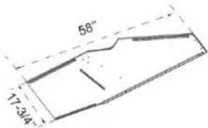
58" 17-3/4"P7 - Terzino destro
Gamba per mobile
(1 pz)
text_image
58" 17-3/4"text_image
23-1/4" 16-1/2"text_image
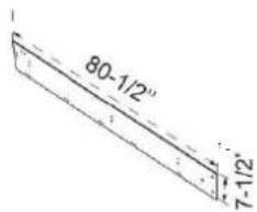
80-1/2" CM 7-1P13 - Grembiule lato sinistro (1 pz)
text_image
80-1/2" 7-1/2"P14 - Grembiule lato destro
(1 pz.)
text_image
3-1/2" 78-3/8"text_image
3-1/2" 78-3/8"text_image
Angled Aprons this end. H2 P14 P19 Playfield Upside Down P13 Flush End Flush End Ramp this end. Playfield sets down into the "Lips" --- both sides. Arrossire FIGURE 21pc - P33 Plastic Connector (Playfield to Front Leg)
STEP 4
Connect the STEP 3 Front Leg Assembly onto the Playfield Assembly using the P33 Plastic Connector as shown in FIGURE 4.
text_image
Front Leg byfield B3 Plastic Figure 4. Front Leg Assembly DETAIL E Playfield Assembly P33 FIGURE 4PARTI RICHIESTE
Viti tonde Phillips, H3
text_image
Numero 30 H3P Buchi dell'isola
Tighten, but DO NOT strip out H2 screws.
text_image
NOT strip out H2 screws. P24 DETAIL 1 P20 H2 P25 P26 FIGURE 10PARTI RICHIESTE
natural_image
Technical line drawing of a mechanical device with labeled component H1, showing internal components and mounting brackets (no text or symbols beyond label)PARTI RICHIESTE 6
1 pz - P27 Plexiglass trasparente
pezzi - Vite a testa tonda Phillips H3
PASSO 18
text_image
P7 P8 This wire is from the Scorer H1 P12 Pilot Holes This connector is from the bottom Interruttore ON/OFF FIGURA 19PARTI RICHIESTE
text_image
Flush H3 P31 P32 H3 Flush Pilot Holes H3 P35 H3 P35 H3 IMPORTANT NOTE: Smaller side to inside IMPORTANT NOTE: Longer, wider side to outside FIGURE 21CONNESSIONI ELETTRONICHE
Machine Translated by Google
text_image
11-1/2" 18-1/4"text_image
23-1/2" 26-1/4"text_image
58" 17.3/4"text_image
58" 17-3/4"text_image
23-1/4" 16-1/2"text_image
80-1/2" 7-1/1"text_image
80-1/2" 7-1/2"text_image
3-1/2" 78-3/8"text_image
3-1/2" 78-3/8"Machine Translated by Google
Machine Translated by Google
PIEZAS REQUERIDAS
text_image
Angled Aprons this end. H2 P14 P19 Playfield Upside Down P13 Flush End Flush End Ramp this end. Playfield sets down into the "Lips" --- both sides. Enjuagar FIGURE 21pc - P33 Plastic Connector (Playfield to Front Leg)
STEP 4
Connect the STEP 3 Front Leg Assembly onto the Playfield Assembly using the P33 Plastic Connector as shown in FIGURE 4.
text_image
Front Leg byfield B3 Plastic Figure 4. Front Leg Assembly DETAIL E Playfield Assembly P33 FIGURE 4PIEZAS REQUERIDAS
Tighten, but DO NOT strip out H2 screws.
text_image
NOT strip out H2 screws. P24 DETAIL 1 P20 H2 P25 P26 FIGURE 10PIEZAS REQUERIDAS
text_image
P7 P8 This wire is from the Scorer H1 P12 Pilot Holes This connector is from the bottom FIGURA 19text_image
Flush H3 P31 P32 H3 Flush Pilot Holes H3 P35 H3 P35 H3 FIGURE 21 IMPORTANT NOTE: Smaller side to inside IMPORTANT NOTE: Longer, wider side to outsideMachine Translated by Google
text_image
11-1/2" 18-1/4"text_image
23-1/2" 26-1/4"text_image
58" 17-34"text_image
58" 17-3/4"text_image
23-1/4" 16-1/2"text_image
23-1/2" 8"-1/2"text_image
80-1/2" CM 7-1"text_image
80-1/2" 7-1/2"text_image
3-1/2" 78-3/8"text_image
3-1/2" 78-3/8"text_image
17-3/8" 3-1/2" Black Painting 18-1/4" 79-1/4"Machine Translated by Google
Machine Translated by Google
CZEŚCI POTRZEBNE
text_image
Angled Aprons this end. H2 P14 P19 Playfield Upside Down P13 Flush End Flush End Ramp this end. Playfield sets down into the "Lips" --- both sides. Splukać FIGURE 21pc - P33 Plastic Connector (Playfield to Front Leg)
STEP 4
Connect the STEP 3 Front Leg Assembly onto the Playfield Assembly using the P33 Plastic Connector as shown in FIGURE 4.
text_image
Front Leg byfield B3 Plastic Figure 4. Front Leg Assembly DETAIL E Playfield Assembly P33 FIGURE 4CZEŚCI POTRZEBNE
natural_image
Technical line drawing of a mechanical component with no visible text or symbolsP24 H3
Dziury na wyspach
P24
CZEŚCI POTRZEBNE
Tighten, but DO NOT strip out H2 screws.
text_image
NOT strip out H2 screws. P24 DETAIL 1 P20 H2 P25 P26 FIGURE 10CZEŚCI POTRZEBNE
natural_image
Technical line drawing of a mechanical device with labeled component H1, showing internal components and mounting brackets (no text or symbols beyond label)text_image
P7 P8 This wire is from the Scorer H1 P12 Pilot Holes This connector is from the bottom Przełącznik WŁ./WYL. RYCINA 19CZEŚCI POTRZEBNE
text_image
Flush H3 P31 P32 H3 Flush P35 H3 H3 P35 H3 Pilot Holes H3 FIGURE 21 IMPORTANT NOTE: Smaller side to inside IMPORTANT NOTE: Longer, wider side to outsideMachine Translated by Google
text_image
11-1/2" 18-1/4"P1 - Voorpootschort (1 st)
text_image
23-1/2" 26-1/4"text_image
58" 17.3/4"P7 - Rechtsback Kastpoot (1 st)
text_image
58" 17-3/4"P8 - Linksback Kastpoot (1 st)
text_image
23-1/4" 16-1/2"text_image
80-1/2" CM 7-1P13 - Linkerkant schort (1 st)
text_image
80-1/2" 7-1/2"text_image
3-1/2" 78-3/8"(Met AAN/UIT schakelaar + bedrading)
text_image
3-1/2" 78-3/8"text_image
17-3/8" 3-1/2" Black Painting 18-1/4" 79-1/4"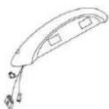
P29 - Electronic Scorer
(1 stuk)
1st - P13 1st - Linkerkant schort
text_image
Angled Aprons this end. H2 P14 P19 Playfield Upside Down P13 Flush End Flush End Ramp this end. Playfield sets down into the "Lips" --- both sides. Doorposten FIGURE 21pc - P33 Plastic Connector (Playfield to Front Leg)
STEP 4
Connect the STEP 3 Front Leg Assembly onto the Playfield Assembly using the P33 Plastic Connector as shown in FIGURE 4.
text_image
Front Leg byfield B3 Plastic Figure 4. Front Leg Assembly DETAIL E Playfield Assembly P33 FIGURE 4VEREISTE ONDERDELEN
Tighten, but DO NOT strip out H2 screws.
text_image
NOT strip out H2 screws. P24 DETAIL I P20 H2 P25 P26 FIGURE 10VEREISTE ONDERDELEN
1st - ÿ P8 Linkerachterbeen
P28 Achterbord - D
natural_image
Technical line drawing of a mechanical device with labeled component H1, showing internal components and mounting brackets (no text or symbols beyond label)BENODIGDE
1st - P27 Helder Plexiglas
text_image
P7 P8 This wire is from the Scorer H1 P12 Pilot Holes This connector is from the bottom AAN/UIT-schakelaar FIGUUR 19VEREISTE ONDERDELEN
1 st. - P11 bovenste achterkastbord, 1 st. - A1 netadapter
text_image
Flush H3 P31 P32 H3 Flush Pilot Holes H3 P35 H3 P35 H3 IMPORTANT NOTE: Smaller side to inside IMPORTANT NOTE: Longer, wider side to outside FIGURE 21ELEKTRONISCHE VERBINDINGEN
Machine Translated by Google
text_image
11-1/2" 18-1/4"text_image
23-1/2" 26-1/4"text_image
58" 17-34"P7 - Högerback Skåpsben (1 st)
text_image
58" 17-3/4"text_image
23-1/4" 16-1/2"P9 - Backboard med grafik (1 PC)
text_image
80-1/2" CM 7-1/2"(1 st)
(1 st)
(1 st)
text_image
80-1/2" 7-1/2"text_image
3-1/2" 78-3/8"text_image
3-1/2" 78-3/8"text_image
17-3/8" 3-1/2" Black Painting 18-1/4" 79-1/4"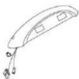
P29 - Electronic Scorer
(1 st)
A1 - A/C Adapter (1 st)

A2 - Bolla
(4 st)
DELAR KRÄVS
text_image
Angled Aprons this end. H2 P14 P19 Playfield Upside Down P13 Flush End Flush End Ramp this end. Playfield sets down into the "Lips" --- both sides. Spola FIGURE 21pc - P33 Plastic Connector (Playfield to Front Leg)
STEP 4
Connect the STEP 3 Front Leg Assembly onto the Playfield Assembly using the P33 Plastic Connector as shown in FIGURE 4.
text_image
Front Leg byfield B3 Plastic Figure 4. Front Leg Assembly DETAIL E Playfield Assembly P33 FIGURE 4DELAR KRÄVS
Support Board 6st - P30 Svart plast "L"
fäste
12st -H3 Phillips Round Head Skruv
STEG 7
FIGUR 7
H3
DETAIL G
P25
text_image
P30 H3P24 H3
PÖ Holes
P24
Dessa rundade utskärningar
DELAR KRÄVS 2st - H3
Phillips Round Head Screw
STEG 9
text_image
Tighten, but DO NOT strip out H2 screws. P24 DETAIL I P20 H2 P25 P26 FIGURE 10DELAR KRÄVS
1st - P22 Goal Box Bottenbräda
1st - P7 Höger bakre ben
Phillips Round Head Screw
STEG 14
Phillips Round Head Screw
STEG 18
Phillips Round Head Screw
STEG 19
text_image
P7 P8 This wire is from the Scorer H1 P12 Pilot Holes This connector is from the bottom ON/OFF-brytare FIGUR 19DELAR KRÄVS
1st - P11 Upper Back Cabinet Board 1st - A1 A/C Adapter
6st - H1 Phillips Round Head Screw 2st - H2 Ph" lips Round Head Screwy
STEG 20
Phillips Round Head Screw