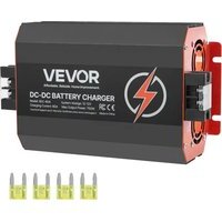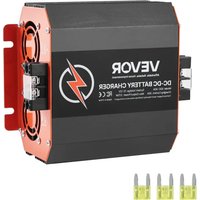
SDC-30A - Toys Vevor - Free user manual and instructions
Find the device manual for free SDC-30A Vevor in PDF.


User questions about SDC-30A Vevor
0 question about this device. Answer the ones you know or ask your own.
Ask a new question about this device
Download the instructions for your Toys in PDF format for free! Find your manual SDC-30A - Vevor and take your electronic device back in hand. On this page are published all the documents necessary for the use of your device. SDC-30A by Vevor.
USER MANUAL SDC-30A Vevor
Affordable. Reliable. Home Improvement.
DC-DCBATTERYCHARGER
MODEL:SDC-20A,SDC-30A,SDC-40A,SDC-60A
TechnicalSupportandE-WarrantyCertificate
www.vevor.com/support
MODEL:SDC-20A,SDC-30A,SDC-40A,SDC-60A
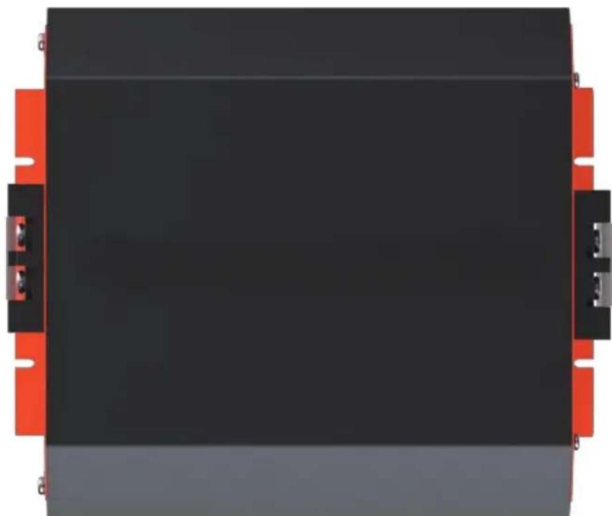
natural_image
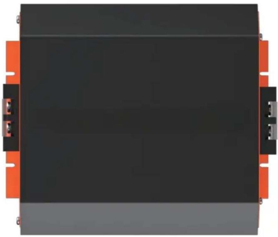
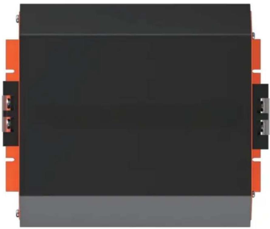
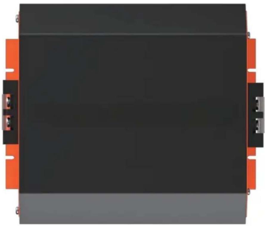
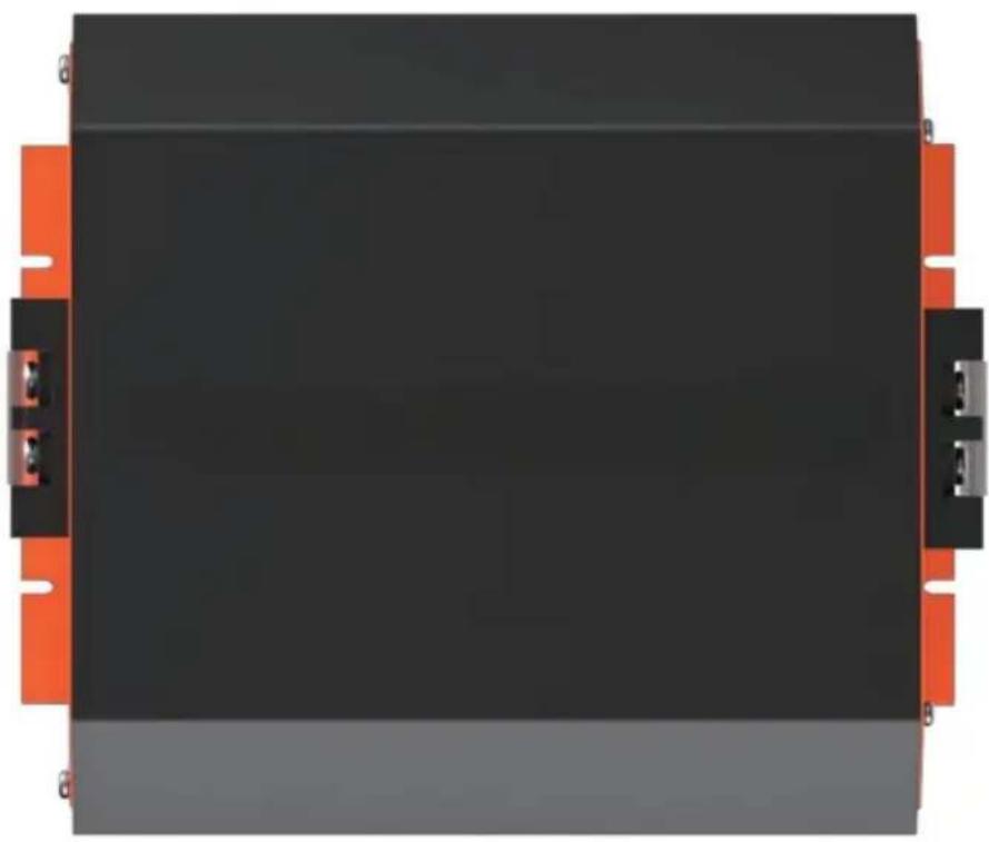
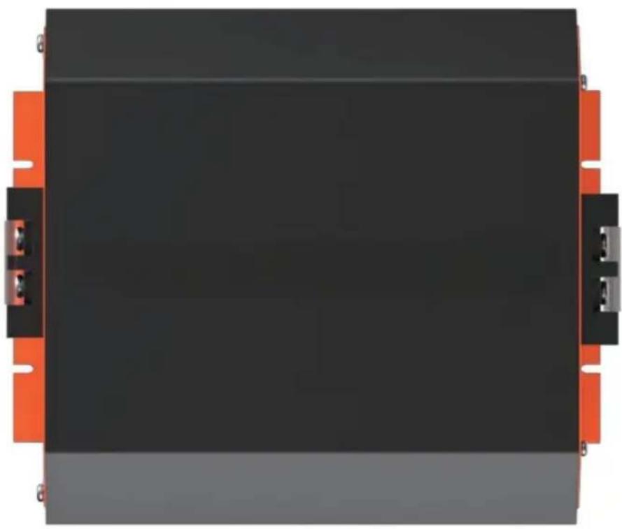
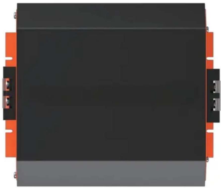
Top-down view of a black rectangular electronic component with red and gray side connectors (no text or symbols visible)(Thepictureisforreferenceonly, pleaserefertotheactualobject)
Thisistheoriginalinstruction, pleasereadallmanualinstructions carefullybeforeoperating.VEVORreservesaclearinterpretationofour usermanual.Theappearanceoftheproductshallbesubjecttothe productyoureceived.Pleaseforgiveusthatwewon'tinformyouagainif thereareanytechnologyorsoftwareupdatesonourproduct.

Important Safety Instructions

Please save these instructions.
This manual contains important safety, installation, and operating instructions for the charger. The following symbols are used throughout the manual to indicate potentially dangerous conditions or important notes.
WARNING
Indicates a potentially dangerous condition. Use extreme caution when performing this task.
CAUTION
Indicates a critical procedure for the safe and proper installation and operation of the controller.
NOTE
Indicates a procedure or function that is important to the safe and proper operation of the controller.
The manufacturer accepts no liability for damage by:
• Faulty assembly or connection
- Damage resulting from mechanical influences or excess voltage
- Modification or tampering with the unit without expressed permission from the manufacturer
• Used for purposes other than described in this manual

General safety
WARNING
Risk of electric shock, fire hazard, or injury. To minimize risk:
- Ensure the positive and negative terminals for the charger do not come into contact
- Firmly secure cables and connections.
- Disconnect the product from the battery each time before cleaning or before making changes to the circuit.
- Do not use the product if physically damaged or with visibly cracked cables. Contact the manufacturer, customer service to prevent safety hazards
- Do not attempt to repair the charger. Inadequate repairs may cause serious injury.
- Electrical devices are not toys—keep away from children.

Installation Safety
- This charger is for 12V battery banks only. Make sure your voltage specification is within the input voltage range expressed.
- Install and store the product in a dry and cool place. Keep away from liquids! Do not expose the product to heat sources such as direct sunlight or other heating elements.
-
Never mount in areas with increased levels of dust or gas-explosion risk!
-
Ensure secure location where it cannot tip or fall
- For installation on boats: if the electrical devices are incorrectly connected, this can lead to corrosion damage on the boat. Verify installation with a qualified electrician or installer.
- Lay cables so they cannot be damaged by doors or be a tripping hazard. Damaged cables can lead to serious injury
- Use ductwork or cable ducts if necessary, to lay cables through metal plates or other panels
- Do not lay AC and DC cable in the same conduit and do not pull on the cables.
Operation Safety
- Warning—Explosion Risk! Batteries can give off explosive hydrogen gas that can be ignited by sparks or electrical connections. Make sure the area is well-ventilated.
- Do not operate in salty, wet, or damp environments; in the vicinity of corrosive fumes; in the vicinity of combustible material; in areas with risks of explosions
- Please be aware that parts of this product may still produce voltage even after disconnected or activation of fuse.
- Do not disconnect cables while the product is operating
Battery Safety
- Warning—Explosion Risk! Batteries may contain corrosive acids or fumes. Avoid contact with battery acid. If your skin comes into contact, thoroughly wash the affected area with water. Any other injuries should seek medical care.
- Avoid wearing metal objects such as watches or rings when working with batteries. Short circuit risk!
- Use only rechargeable deep cycle batteries. NEVER attempt to charge a frozen or defective battery.
- Wear goggles, gloves, or other or protective clothing when working with batteries. Do not touch your eyes.
- Ensure proper cable sizing for batteries! Over-current protection devices should be on the positive line.
- Refer to your battery manufacturer for battery maintenance and care
- When removing a battery, power off all loads first, then disconnect it from the circuit before removing.
Table of Contents
Safety Information 01
General Information 04
Product Overview 05
Identification of Parts 05
Dimensions 06
Optional Components 07
Installation 07
Location Considerations 07
Wiring and Fusing 09
Grounding 09
DC Output Wiring (House) 10
DC Input Wiring (Starter) 11
D+ Ignition Wiring 12
LC Current Limit Wiring 14
Operation 15
LED Indicators 15
Setting Battery Type 15
Setting Lead Acid 16
Setting Lithium 17
Battery Charging Logic 18
Lithium Activation 18
Troubleshooting 19
Maintenance 21
Technical Specifications 22
Temperature Compensation 22
General Information
The DC-DC Series battery chargers are the most effective way to charge your auxiliary or house batteries from the alternator/starter battery. Compatible with smart or traditional alternator types, the DC-DC offers correct charging for AGM, Flooded, Gel, and even Lithium deep cycle batteries! Featuring a 3-stage battery charger and multiple electronic protections, owners can feel confident that their batteries are being charged optimally and automatically. Easily install the compact yet sturdy DC-DC on RV's, commercial vehicles, boats, yachts and many more applications.
Key Features
- Compatible with multiple 12V batteries: AGM, Flooded, Gel, Sealed, Lithium-iron Phosphate and Lithium-ion
- Smart protections features including Over-voltage, Over-Temperature, and reverse polarity!
- Battery Isolation and Battery Charger in one
- Compact yet built tough for all conditions
• 3-Stage Battery Charger get your batteries to 100%
Check the charging requirements from the battery manufacturer before charging your battery with this unit.
Product Overview
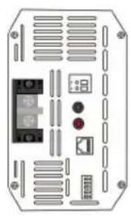
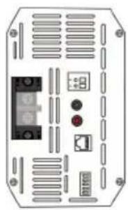
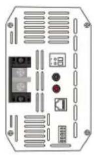
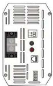
Identification of Parts
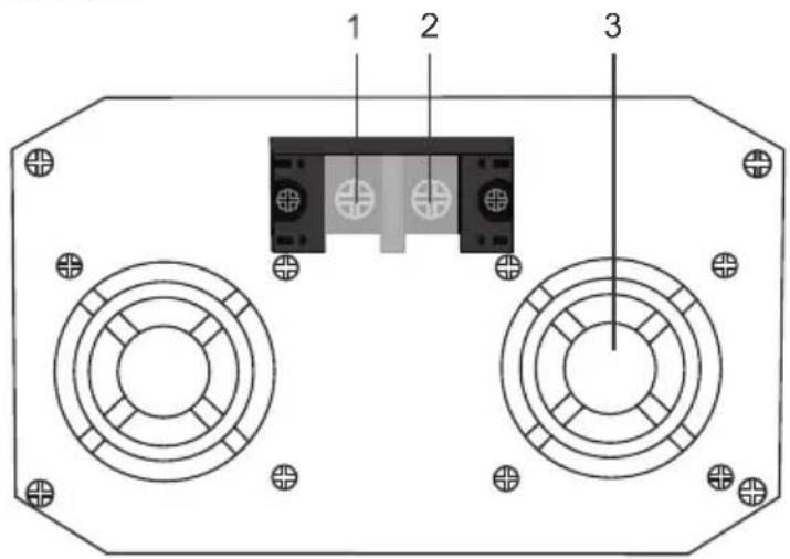
text_image
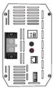
1 2 3Key Features
- Negative DC Input Terminal
- Positive DC Input Terminal
- Ventilation Fans
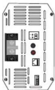
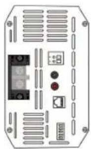
text_image
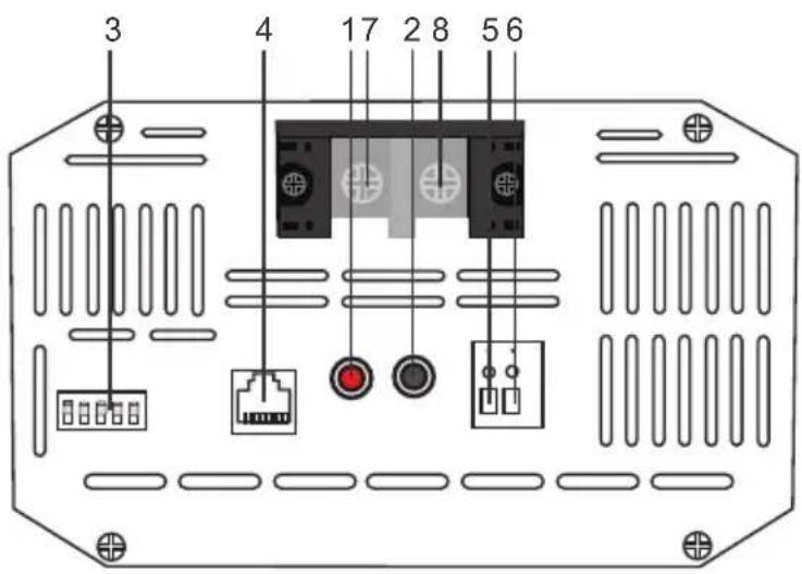
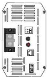
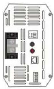
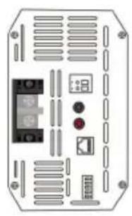
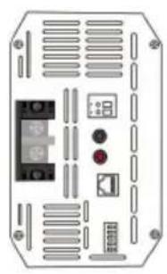
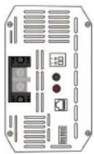
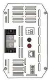
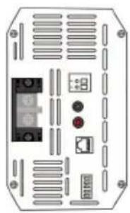
3 4 17 2 8 5 6DC Output Side
Key Features
- Power LED
2.Fault LED
3.Dip Switches
4.RJ11 Temperature Sensor Port (requires separate purchase)
5.D+ Ignition Terminal
6.LC Terminal – Current Limiting Terminal
7. Positive DC Output Terminal
8. Negative DC Output Terminal
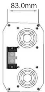
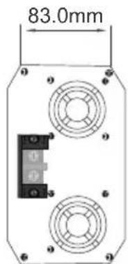
Dimensions
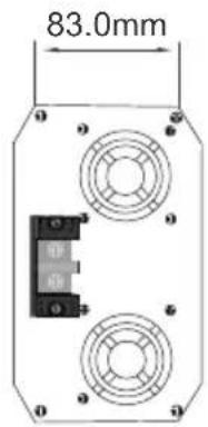
text_image
83.0mmDCC1212-20
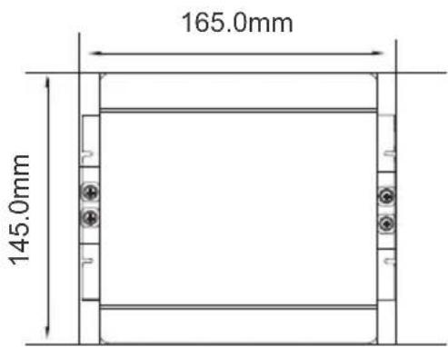
text_image
165.0mm 145.0mm
natural_image
Front view of an electronic device casing with ventilation grilles and control buttons (no visible text or symbols)The dimensions have a ±0.5mm tolerance
text_image
83.0mmDCC1212-40
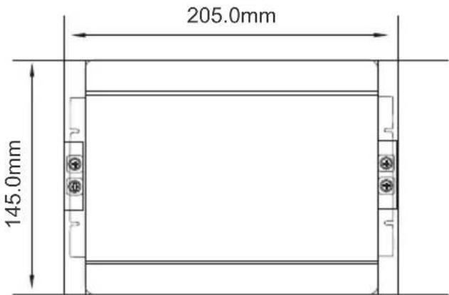
text_image
205.0mm 145.0mm
natural_image
Front view of a device casing with internal components and ventilation slots (no text or symbols visible)The dimensions have a ±0.5mm tolerance
text_image
83.0mmDCC1212-60
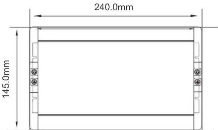
text_image
240.0mm 145.0mm
natural_image
Front view of a device chassis with labeled ports and connectors (no readable text or symbols)The dimensions have a ±0.5mm tolerance
Optional Components
DC-DC Temperature Sensor (Model: RTSDCC)

Do not use with Lithium batteries.
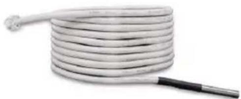
natural_image
Coiled white cable with a black handle, isolated on white background (no text or symbols)The RTSDCC comes in handy for reading incoming temperature values from the house battery bank while adjusting the charging voltage of your DC to DC On-Board Battery Charger. Featuring a temperature operation range from -4^ 176^ / -20^ +80^ , the sensor will be important in the overall lifespan and performance of your house battery bank by applying higher charging voltage to counter the increased resistance due to low temperature. Simply connect the RTSDCC to the charger and place the sensor on top or on the side of the house battery bank and the charger will take care of the rest with temperature compensation.
Installation
DANGER
- Never mount the product in areas where there is a risk of gas or dust explosion.
CAUTION
- Ensure a secure stand! The product must be set up and fastened in such a way that it cannot tip over or fall down.
NOTICE
- Do not expose the product to any heat source (such as direct sunlight or heating). Avoid additional heating of the product.
- Set up the product in a dry location protected from splashing water.
Location Considerations
- The battery charger can be installed horizontally as well as vertically.
- The battery charger must be installed in a place that is protected from moisture.
- The battery charger may not be installed in the presence of flammable materials.
- The battery charger may not be installed in a dusty environment.
- The place of installation must be well ventilated. A ventilation system must be available for installations in small, enclosed spaces. The minimum clearance around the batterycharger must be at least 5cm.
- The device must be installed on a level and sufficiently sturdy surface.
When selecting a location for the DC-DC, make sure that the unit is as close as possible to the battery you will be charging (auxiliary battery). The charger may be mounted on the cabin of the vehicle, along a chassis rail, the inner guard of a vehicle, behind the grille or headlight or even on the side of the radiator. However, you want to make sure that the area is not susceptible to moisture or other substances as well as potentially high temperatures.
The DC-DC would operate best if there is some air flow.

Mounting
- Have at least 5cm of clearance from all areas and ensure some ventilation for best performance
- Trace the mounting holes with a pencil/pen when placing the DC-DC against the desired area
- Use 4 x screws to secure the dc-dc onto a surface
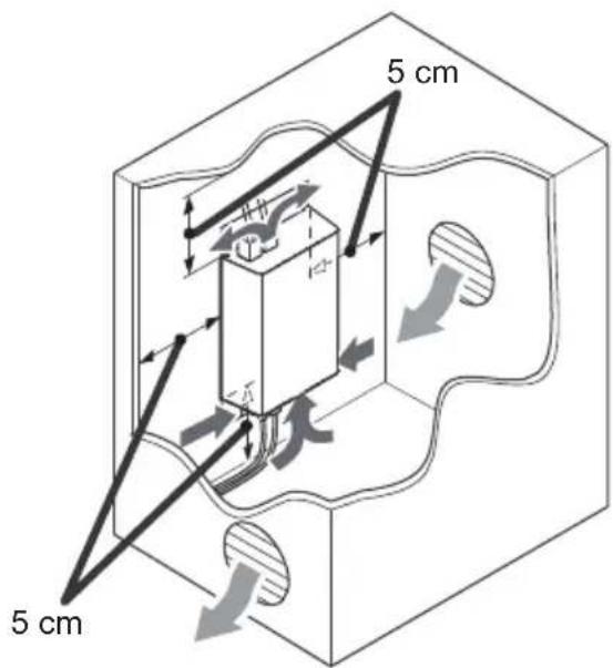
text_image
5 cm 5 cm
natural_image
Diagram of a computer monitor with a pencil inserted, showing a scroll and cable (no text or symbols present)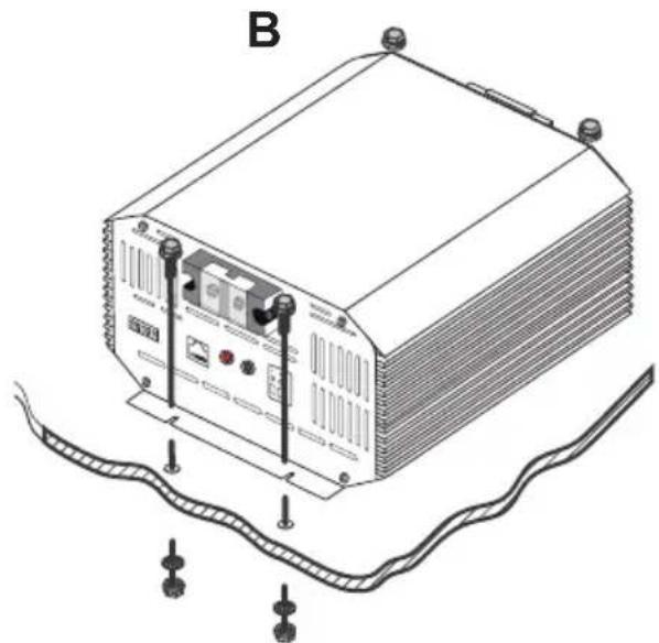
natural_image
Line drawing of a rectangular electronic device with mounting points and wiring, no text or symbols presentWiring and Fusing
Battery Ring terminals are recommended for 12V input and output connections. The following is a reference incorporating a critical 0-3% max voltage drop and may not cover all unique applications that may exist. When the battery charger is sending the rated amps, the input side may experience a draw higher current draw by a factor of up to 50%. Larger wire sizes generally improve performance, whereas smaller wire sizes may reduce performance, especially if undersized. When considering wiring, fusing, and connection options, think big and short as possible as heavier components and shorter wire length offer less resistance and voltage drop. Terminal Size Limitations may apply. The installer is responsible for ensuring that the correct cable and fuse sizes are used when installing the DC-DC battery charger.
| CableModel | Cable Length/ Min AWG | Recommended Fuse | |||
| 0 ~ 10ft / 0 ~ 3m | 11 ~ 20ft / 3 ~ 6m | 21 ~ 30ft / 6 ~ 9m | |||
| DCC-1212-20 | To DC Input (Starter) | 30A or close10AWG 8-6A | |||
| To DC Output (House) | 12AWG 10-8AWG 6AWG | 25A or close | |||
| DCC-1212-40 | To DC Input (Starter) | 6AWG 4AWG | 4AWG* 60A or close | ||
| To DC Output (House) | 50A or close8AWG 8-6AV | ||||
| DCC-1212-60 | To DC Input (Starter) | 4AWG | 4AWG* | 4AWG* 90A or close | |
| To DC Output (House) | 6AWG 4AWG | 4AWG* 75A or close | |||
*3-10% Non-Critical Voltage Drop

Grounding
NOTE
Depending on the application, the grounding point may differ.
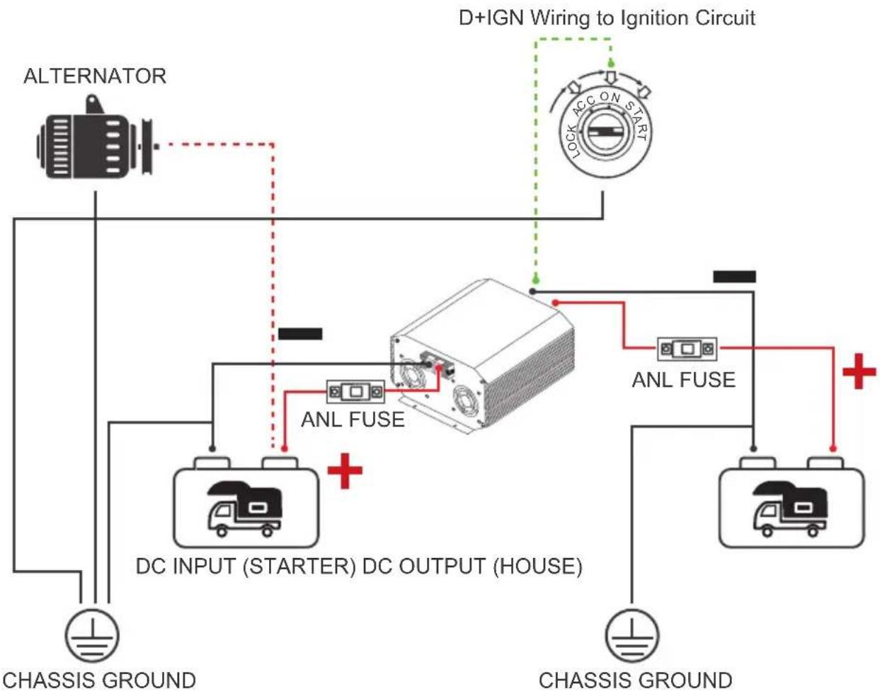
The DC-DC share a common negative ground meaning that there should be only one common ground point between all batteries and electronics typically seen in either chassis/body ground, a canopy, a trailer, or even the vehicle battery negative connection. In most cases, connecting the starter and house battery directly to the DC-DC is enough for a grounding application. You will not ground the body of the DC-DC. In the illustration below, the two batteries are connected to the same chassis ground point.
flowchart
graph TD
    A["ALTERNATOR"] --> B["DC INPUT (STARTER) DC OUTPUT (HOUSE)"]
    B --> C["ANL FUSE"]
    C --> D["AND Gate"]
    D --> E["D+IGN Wiring to Ignition Circuit"]
    E --> F["CHASSIS GROUND"]
    F --> G["CHASSIS GROUND"]
    H["LOCK ACC ON START"] --> I["AnL Fuse"]
    I --> J["AND Gate"]
    J --> K["CHASSIS GROUND"]
    L["CHASSIS GROUND"] --> M["AND Gate"]
    M --> N["CHASSIS GROUND"]

DC Output Wiring (House)
WARNING
Only use 12V batteries. Damages due to connecting higher voltage batteries will not be covered in warranty.
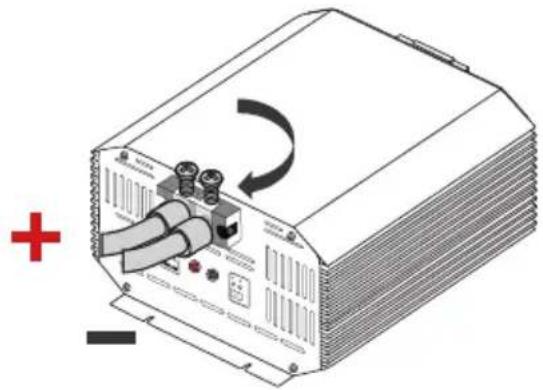
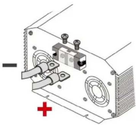
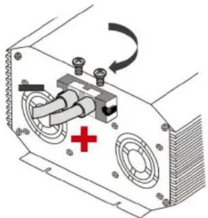
The DC-DC output will connect to the 12V auxiliary or house battery that you are intending to charge. These batteries may be a different chemistry from the starter battery. The DC-DC input and output terminals are isolated, meaning that the output voltage can be kept stable without interference from the input circuit. This ensures stable and correct charging of auxiliary batteries. It is best to place the DC-DC closer to the battery you will be charging primarily.
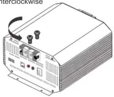
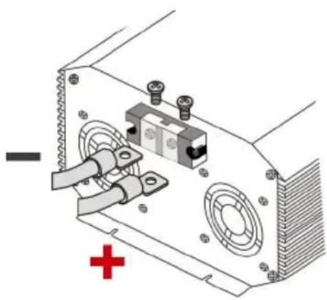
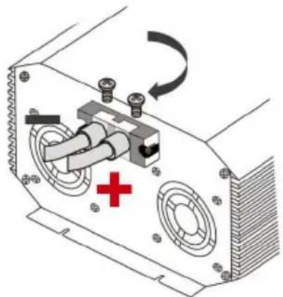
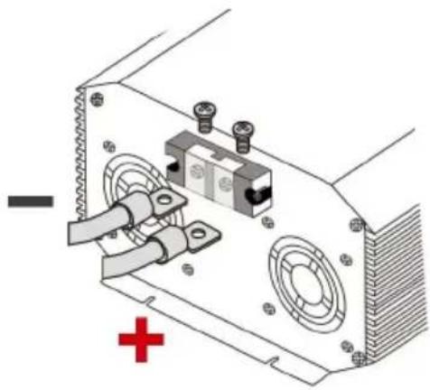
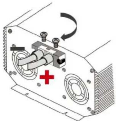
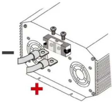
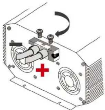
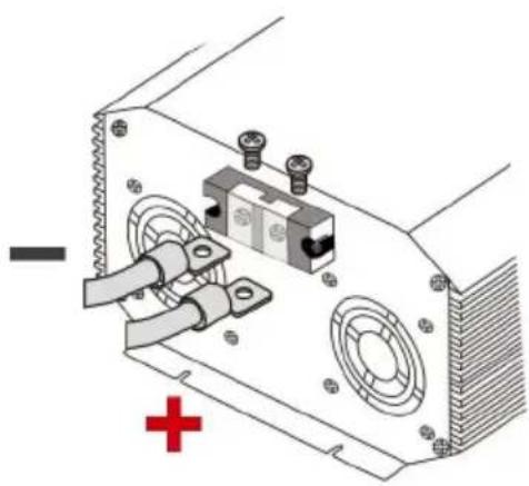
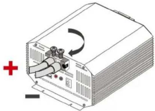
- Use a screwdriver to loosen the DC output terminals by rotating counterclockwise (CCW)
- Connect a ring terminal cable from House Battery Positive to the Positive DC Output Terminal
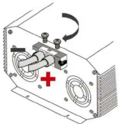
- Use a screwdriver to tighten the DC output terminal by rotating clockwise (CW)
- Repeat for the House Battery Negative to the Negative DC Output Terminal
1 counterclockwise
natural_image
Illustration of a portable electronic device with ports and buttons, no visible text or symbols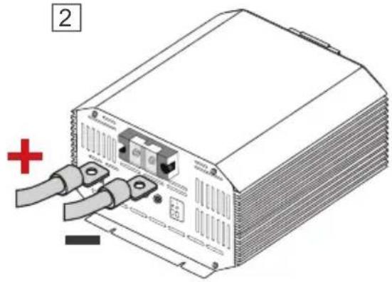
natural_image
Illustration of a server rack with two cables and a red plus symbol (no text or labels)3 clockwise
natural_image
Illustration of a power supply unit with cable and indicator lights, no visible text or symbolsDC Input Wiring (Starter)
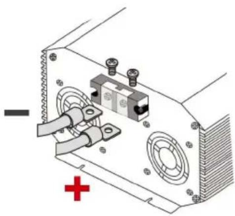
The DC-DC will not power on or operate until the D+ ignition cable is connected.
When connecting the DC input, note that the DC-DC will still be off until the D+ ignition cable voltage senses.
The DC-DC input will connect to the 12V starter battery that will be used to charge your auxiliary or house battery. The starter battery may be a different chemistry from the house battery.
The DC-DC input and output terminals are isolated, meaning that the output voltage can be kept stable without interference from the input circuit. This ensures stable and correct charging of auxiliary batteries.
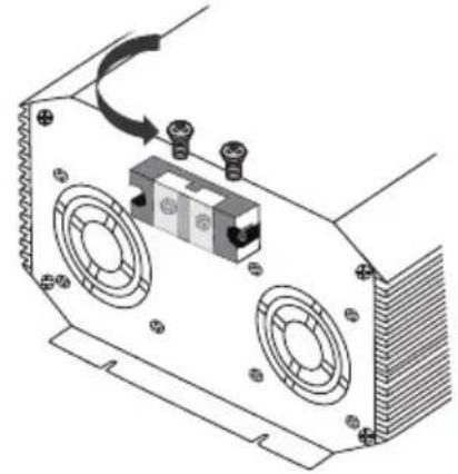
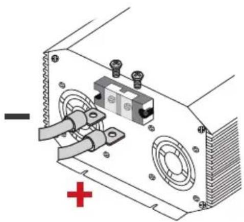
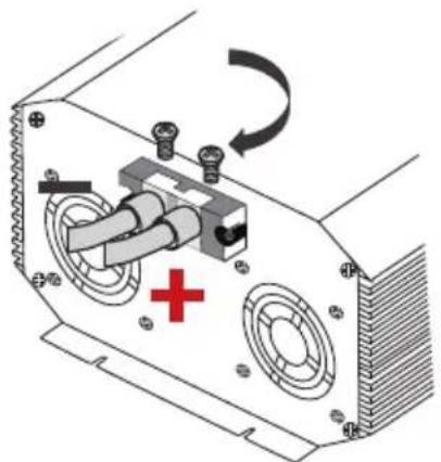
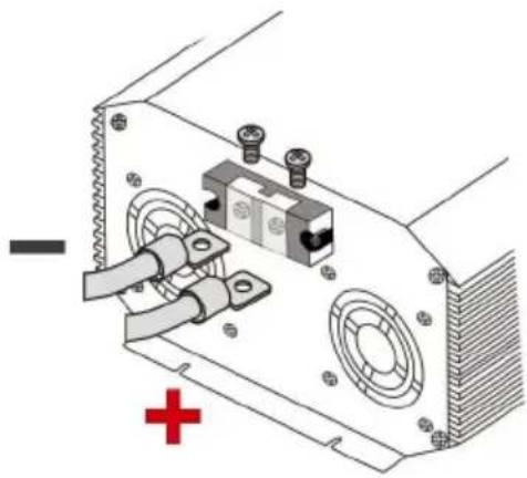
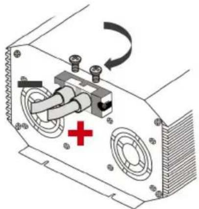
- Use a screwdriver to loosen the DC input terminals by rotating counterclockwise (CCW)
- Connect a ring terminal cable from Starter Battery Positive to the Positive DC Input Terminal
- Use a screwdriver to tighten the DC Input terminal by rotating clockwise (CW)
- Repeat for the Starter Battery Negative to the Negative DC Input Terminal
1 counterclockwise
natural_image
Technical diagram of a mechanical or electronic component with mounting holes and a central housing (no text or symbols visible)2
natural_image
Technical diagram of an electronic device showing ports, connectors, and a central component with a red cross symbol (no text or labels)3 clockwise
natural_image
Diagram of an electronic device showing a switch, battery, and cooling unit with a red cross symbol (no text or labels)D+ Ignition Wiring
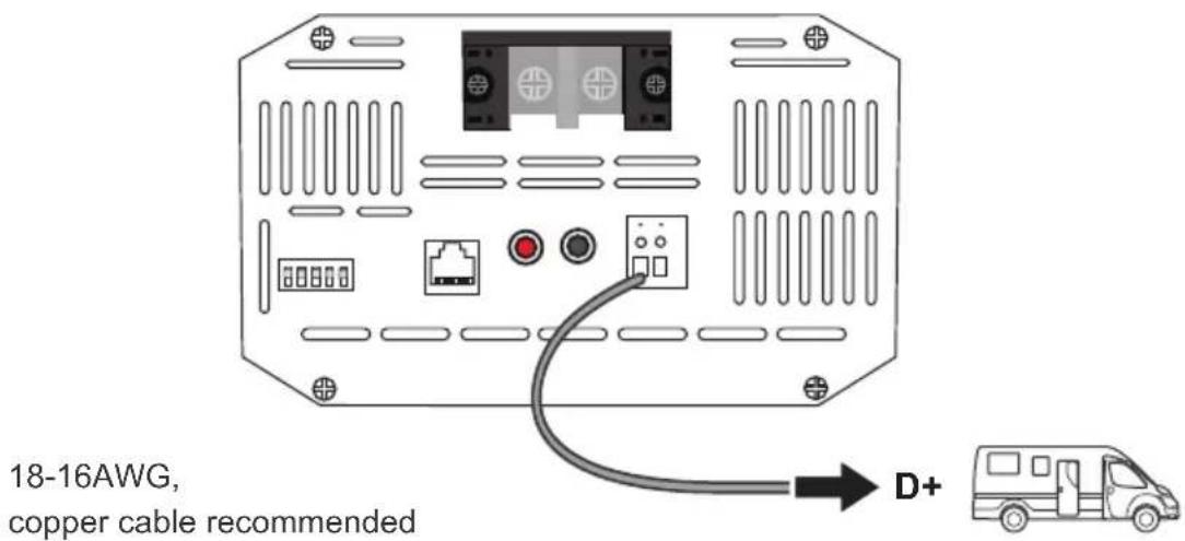
The D+ terminal will be located on the output side but connects to the DC ignition circuit of the input starter battery. This may be in the engine bay fuse block for some vehicles. Refer to your own vehicle's electrical diagram for D+ wiring placement. May require splicing or cable adjustments to connect correctly to your ignition circuit.
text_image
18-16AWG, copper cable recommended D+The DC-DC will not power on or operate until the D+ ignition cable is connected to the ignition circuit where it will detect a 12V source to operate ON. The purpose is to toggle the DC-DC switch on when the vehicle is running with the alternator to prevent the DC-DC from operating incorrectly with just the starter battery leaving you with a drained starter battery. Use 18-16AWG copper cable. You may need a multi-meter to test your connections to verify placement of the D+ wire.
Alternator Recommendation
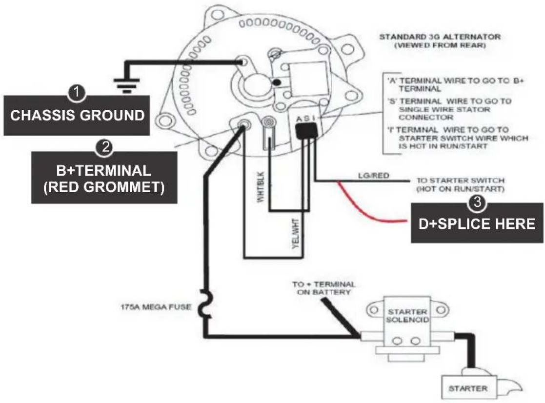
Check your alternator and identify the number of terminals. Most alternators will have 3 wires connected (BATT+, BATT-, IGN). The following is an example and may not match your application. Refer to your vehicle's documentation and part for actual wiring
| 1 | BATT+ | Could be labeled as “B”, “Bat”, or “Pos”. This will connect directly to the battery and typically be heavy gauge for high current applications. |
| 2 | BATT- | Could be labeled as “Neg”, “Field” or “F”. This will connect to ground. Some alternators may not have this as they will be directly grounded to the engine. |
| 3 | IGN | Could be labeled “IGN” or “L” and will likely be the smaller terminal. This connects to the ignition circuit or dashboard warnings signs. This is where you will want to splice the D+ ignition cable. |
text_image
CHASSIS GROUND B+TERMINAL (RED GROMMET) 1 2 3 STANDARD 3G ALTERNATOR (VIEWED FROM REAR) 'A' TERMINAL WIRE TO GO TO B+ TERMINAL 'S' TERMINAL WIRE TO GO TO SINGLE WIRE STATOR CONNECTOR 'I' TERMINAL WIRE TO GO TO STARTER SWITCH WIRE WHICH IS HOT IN RUN/START LG/RED TO STARTER SWITCH (HOT ON RUN/START) D+SPLICE HERE 175A MEGA FUSE TO + TERMINAL ON BATTERY STARTER SOLENCID STARTEREngine Bay Fuse Block Recommendation
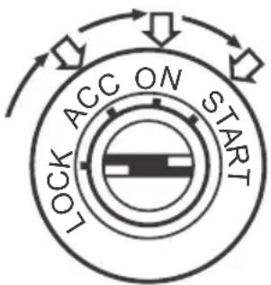
Review your vehicle's fuse layout diagram to identify a fuse location that is live when the vehicle is running with the alternator. Key positions in the ignition are typically lock, accessory, on, and start.
| LOCK | Off position where no accessories will work, and steering is also likely locked |
| ACCESSORY | Accessories are given power such as radio and some other small electronics. |
| ON | Turns on all your electronics. The key will default into this position after cranking in START. Splicing of fuse block will need to be live when the key is in reverting back to this position |
| START | Cranks the engine on and reverts to ON position. |
You may need to test the fuse location by checking the voltage with a multi-meter and making sure it's live only when the vehicle is in the Start/Run position. This will help in identifying where to connect if the fuse layout does not have an IGN position. The easiest connections when splicing can be made when using a fuse holder splice connector.
flowchart
graph TD
    A["LOCK"] --> B["ACC"]
    B --> C["ON"]
    C --> D["START"]
    D --> E["Arrow Right"]
    E --> F["Arrow Down"]
    F --> G["Arrow Up"]
    G --> H["Arrow Left"]
    H --> I["Arrow Left"]
    I --> J["Arrow Left"]
LC Current Limit Wiring
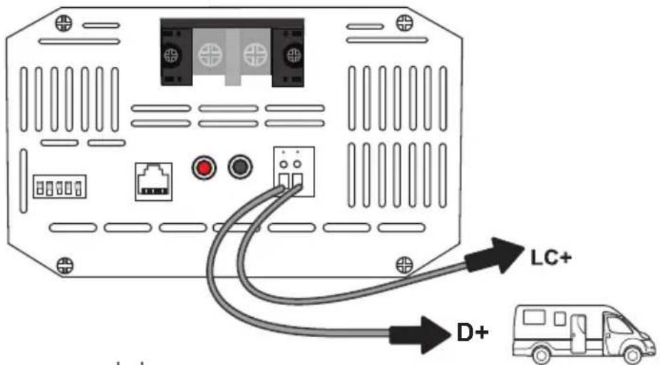
The DC-DC battery chargers feature 50% current limiting from the rated specification when connecting the LC Terminal to a 12V source. Current Limiting is instant and recommended to be connected to the same location as the D+ ignition cable. Alternatively, you can toggle current limiting to your liking by connecting the LC terminal to starter battery positive terminal. In this fashion, current limiting will always take until removing the LC wire from the battery terminal to revert to the normal amp rating. Use 18-16AWG copper cable for the LC terminal and you may need to splice your own connections for the other cable end depending on your connection point.
| Amp RatingModel Current Limit | |
| DCC1212-20 20A 10A | |
| DCC1212-40 40A 20A | |
| DCC1212-60 60A 30A |
text_image
LC+ D+18-16AWG,
copper cable recommended
Operation
Assuming correct 12V battery connections and D+ ignition cable wiring, then the POWER LED will illuminate green.

LED Indicator
Power LED
| StatusCode Meaning | ||
| Green | Off | Powered Off; if abnormal refer to troubleshooting |
| Solid ON Normal | ||
| StatusColor Meaning | ||
| Red | Off | No faults |
| Solid ON Fault detected; refer to troubleshooting | ||

Setting Battery Type

Refer to your battery manufacturer specifications when selecting a battery type via Dip switches. Damage due to incorrect battery settings will not be covered in warranty.
DIP Switches
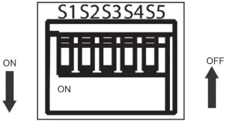
The 5 x dip switches can be configured to charge lead acid or lithium batteries. Note that ON is position down and OFF is position up if facing the dip switches directly. Lead acid profiles have an absorption charge and a float charge whereas lithium batteries will only have an absorption charge and no float charge.
text_image
S1S2S3S4S5 ON ON OFFSetting Lead Acid
Lead acid assumes deep cycle AGM, Gel, Flooded, and Sealed Lead Acid. To get started, make sure SW5 = ON to gear the charger for lead acid batteries. Next select your absorption charge and float charge below by configuring the dip switches to your desired specifications.
| DIP Switch Meaning | |
| SW1, SW2 | Set Absorption Charge Voltage |
| SW3, SW4 | Set Float Charge Voltage |
| SW5 | ON—Lead Acid |
| Set Absorption Charge | ||
| SW1 SW2 | Voltage | |
| ON | ON | 14.4 V |
| OFF ON | 14.1 V | |
| ON OFF | 14.7V | |
| OFF | OFF | |
| Set Float Charge | ||
| SW3 SW4 | Voltage | |
| 13.8 VON ON | ||
| OFF ON | 13.5 V | |
| ON OFF | 13.2V | |
Setting Lithium
To get started, make sure SW5 = OFF to gear the charger for lithium batteries. There will not be a float voltage and instead users will select between Type 1 lithium voltages or switch into Type 2 lithium voltages depending on your lithium battery specifications. You must select a lithium Type to when selecting your charge voltage. Type 1 voltages range from 12.6V \~ 13.0V and Type 2 voltages range from 14.0V\~14.6V.
| DIP Switch | Lithium VoltageDIP Switch | ||||
| SW5=OFF | SW1 | OFF | SW3 SW4 | Voltage | |
| OFF | ON | 13.0V | |||
| SW2 | ON OFF | 12.8 V | |||
| OFF OFF | 12.6V | ||||
| DIP Switch Lithium Voltage | |||||
| SW3 | ON | SW1 SW2 Voltage | |||
| ON ON | 14.6 V | ||||
| SW4 | OFF ON | 14.4 V | |||
| ON OFF | 14.2V | ||||
| OFF OFF | 14.0V | ||||
Battery Charging Logic
line
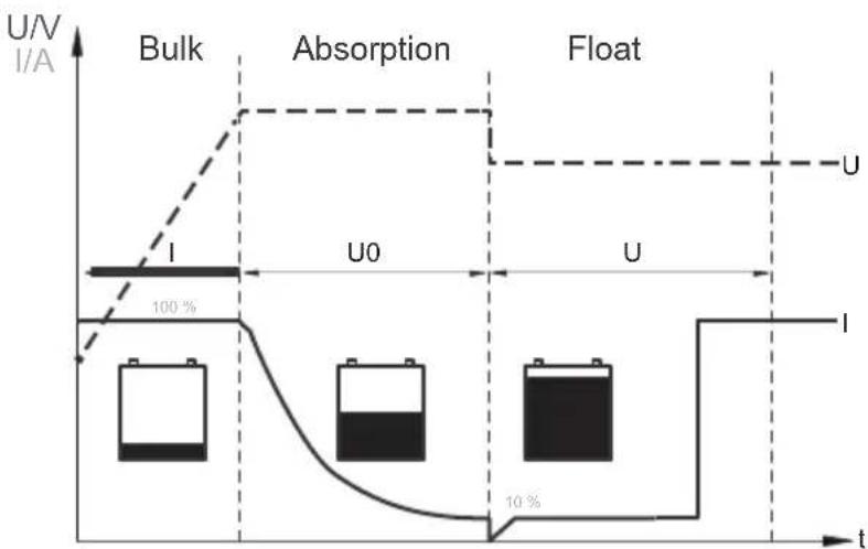
| Phase | Time (t) | U/V (I/A) | |-----------|----------|-----------| | Bulk | U0 | 100% | | Absorption| U | U | | Float | U | U |Bulk (Phase I) (Lead Acid + Lithium)
In the beginning, a discharged battery will be charged with maximum current and voltage will be climbing steadily until reaching the absorption voltage setpoint.
Absorption (Phase U0) (Lead Acid + Lithium)
The battery reaches the absorption voltage setpoint and holds the voltage constant while the current gradually decreases until the battery is becoming full (within 10-20%). By default, absorption will not exceed 3 hours to prevent overcharging.
Float (Phase U) (Only Lead Acid)
After the absorption stage, the voltage of the battery will reduce to the float voltage setpoint and current will also reduce to a low maintenance mode to prevent the battery from discharging and offsetting any self-discharge. Heavier battery discharge may set controller back to Bulk/Absorption to replenish energy lost while energy is available.
Lithium Activation
NOTE
This is an automatic process for Lithium batteries. Ensure correct lithium polarity when connecting to the DC Output.
The DC-DC have reactivation feature to awaken a sleeping lithium battery. The protection circuit of Lithium batteries will typically turn the battery off and make it unusable if over-dis-charged. This can happen when storing a Lithium pack in a discharged state for any length of time as self-discharge would gradually deplete the remaining charge. Without the wake-up feature to reactivate and recharge batteries, these batteries would become unser-viceable and the packs would be discarded. A small charge current will be applied to the house battery to activate the protection circuit and if a correct cell voltage can be reached, it starts a normal charge.
Troubleshooting
If the DC-DC is not functioning correctly, it may be undergoing an internal electronic protection and stop normal operation. This is not indicative of a defective unit but may require some troubleshooting to resume normal operation.
Electronic Protection
| Behavior Protection | Troubleshoot Steps | ||
| Red Fault LED ON | Battery Overvoltage | 1.Use a multi-meter to measure the DC input and DC output batteries as well as the respective DC-DC input/output terminals. Battery over-voltage is 15.5-16V: | |
| High Voltage Shutdown 16V | |||
| High Voltage Restart 15.5V | |||
| 2.Disconnect any other chargers in the circuit and let the battery rest to lower the voltage. Disconnect any sensitive loads.3.Double check correct DIP switches | |||
| Battery Undervoltage | 1.Use a multi-meter to measure the DC input and DC output batteries as well as the respective DC-DC input/output terminals. They should be similar. Battery undervoltage is below 8-10V. | ||
| Low Voltage Cut-out 8V (Lead Acid) | |||
| Low Voltage Restart 10V | |||
| 2.Disconnect any other loads in the circuit and let the battery charge.3.Lead acid batteries below 8V may need an external charger to reach minimum DC-DC voltages; Lithium batteries will be able to recover due to Lithium Activation. | |||
| Reverse Polarity | 1.Use a multi-meter in DC Volts and probe the positive line onto the positive battery terminal and probe the negative line to the negative battery terminal. You should see a reading within 10V~14V and be a positive number.2.If the DC reading is negative, your poles are reversed. Fix the wiring to return to normal operation.WARNING Lithium batteries in reverse polarity may cause irreversible damage to the dc-dc. | ||
| Behavior Protection | Troubleshoot Steps | ||
| Red Fault LED ON | High Temperature | 1. Double check that your wiring is correct with a multi-meter and that the battery levels are suitable within the operating voltage range2. Observe the ambient temperature. Avoid installations in direct sun. Ambient temperatures above 122°F/50°C will cause the unit to stop functioning until conditions get cooler.Move the unit to a cooler location or introduce ventilation into the install location. The protection is automatic, and the dc-dc will resume normal function upon cooling down. | |
| Short Circuit | 1. The DC-DC is experiencing an internal short circuit due to an imbalance between its input and output circuits. Restart the DC-DC by disconnecting the input/output and then reconnecting it again.The error will clear automatically upon a successful restart. If issues continue with a permanent red led, then contact support to address the previous troubleshooting steps. | ||
More Troubleshooting
| Behavior Cause | Fix | |
| Green Power LED OFF, batteries correctly connect- | Incorrect D+ Connection | 1. Check to make sure there is a cable connected between the D+ Terminal (DC Output Side) and the ignition circuit. The D+ needs a 12V signal to start/stop the DC-DC. Splicing required. Refer to your vehicles fuse box layout to identify the ignition line or similar location that is live when the alternator is running. |
| Wrong battery at input/output | 1. Verify correct battery placement with tight and secure corrections, eliminate any breaks.2. DC Input terminals should be the starting battery and should also have a charging source (alternator in this case).3. DC output terminals should be the auxiliary or house battery you're charging. | |
| Battery voltage too low or highConnection break | 1. The DC-DC requires 12V batteries more than 10V (Lead Acid) and can not exceed 15.5V so no 24V batteries.Use a multi-meter to measure the battery terminals and verify that the dc-dc terminals match the respective values (or similar).Continued problems with batteries may need to be taken to a nearby battery tester at your nearby automotive shop.1. Inspect your connections for tight, secure, and undamaged wiring to and from the DC-DC2. Check fuses for any breaks and replace them to continue normal operation.3. Use your multi-meter's (check with manufacturer) continuity test to individually check each line (positive and negative) at the input and output to verify consistent connection. Audible multi-meter Beeps indicate continuity. No sound indicates connection break. | |
Maintenance
For best DC-DC performance, periodically check the unit and related wiring monthly as well as the installation location:
- Inspect the wiring and note any wiring cracks, wear, tear, corrosion, or loose wiring and replace immediately. Inspect wiring terminals and ensure they're tight as they may become loose during vehicle vibrations.
- Check that the battery charger is free of dust, liquids, or heat sources and ensure the DC-DC is receiving some ventilation. Improved ventilation improves performance.
Technical Specifications
| Model | DCC1212-20 | DCC1212-30 | DCC1212-40 | DCC1212-60 |
| Transformation | 12 V → 12 V | |||
| Input Battery Voltage Range | 8V ~ 16VDC | |||
| Rated Charging Current | 20 A | 30 A | 40 A | 60 A |
| Charging Voltage Range | Lead Acid: 13.2V ~ 14.7VLithium: 12.6V ~ 14.6V | |||
| Rated Max Power | 250W | 360W | 500W | 750W |
| Residual ripple of output voltage at rated current | < 50 mV | |||
| Efficiency | 90 % | |||
| Idle power consumption | 0.4 A | |||
| Operational temperature (Ambient) | -4 °F ~ 122 °F/-20 °C to +50 °C | |||
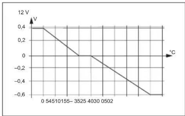
| Temperature Compensation | -3mV/C° /2V | |||
| Humidity | ≤95 % Non-condensing | |||
| Dimensions | 165*145*83mm | 205*145*83mm | 205*145*83mm | 240*145*83mm |
| Weight | 1.8kg | 2kg | 2.4kg | 3kg |
| Terminal Size | M6 x 10mm | |||
| Terminal Torque | 2.2 - 2.6 lbf - in /24.5 - 29.4 N - cm | |||
| Certification | CE | |||

Temperature Compensation
NOTE
The temperature compensation is not to be used with lithium batteries.
line
| Temperature (°C) | Voltage (V) | | ---------------- | ----------- | | 0 | 0.4 | | 545 | 0.4 | | 1055 | 0.2 | | 155 | 0.0 | | 3525 | 0.0 | | 4030 | 0.0 | | 502 | -0.2 | | 602 | -0.4 | | 702 | -0.6 |Manufacturer:Shanghaimuxinmuyeyouxiangongsi
Address:Shuangchenglu803nong11hao1602A-1609shi,baoshanqu,shanghai200000CN.
ImportedtoAUS:SIHAOPTYLTD.1ROKEVASTREETEASTWOOD
NSW2122Australia
ImportedtoUSA:SanvenTechnologyLtd.Suite250,9166Anaheim
Place, Rancho Cucamonga, CA91730
| REPU |
YHCONSULTINGLIMITED.C/OYHConsulting
KlimitedOffice147,CenturionHouse,London
Road, Staines-upon-Thames, Surrey, TW184AX
| REPE |
E-CrossStuGmbH
C MainzerLandstr.69,
60329FrankfurtamMain.

TechnicalSupportandE-WarrantyCertificate
www.vevor.com/support
VEVOR
Affordable. Reliable. Home Improvement.
CHARGEUR DE BATTERIE CC-CC
MODÈLE : SDC-20A, SDC-30A, SDC-40A, SDC-60A
Affordable. Reliable. Home Improvement.
BATTERIE CC-CC
CHARGEUR
MODÈLE : SDC-20A, SDC-30A, SDC-40A, SDC-60A
natural_image
Top-down view of a black rectangular electronic device with orange connectors and labeled pins (no text or symbols on the device itself)text_image
165,0 mm 145,0 mm
natural_image
Front view of a device chassis with labeled ports and connectors (no readable text or symbols)text_image
205,0 mm 145,0 mm
natural_image
Front view of a computer interface panel with buttons and ports (no visible text or labels)natural_image
Front view of an electronic device casing with ports, buttons, and wiring (no visible text or symbols)natural_image
Coiled white cable with black end cap, isolated on white background (no text or symbols)natural_image
Technical diagram of a mechanical or electronic component with two circular parts and a central housing, showing no text or symbols.2
natural_image
Diagram of an electronic device showing a connector with pins and a red cross symbol (no text or labels)3

natural_image
Technical diagram of an electronic device with screw and housing components, no visible text or symbolstext_image
Diagram of an electronic device rear panel with labeled ports and connections to a bus, showing connections via LC+ and D+ cables.Opération
YH CONSULTING LIMITED. A/S YH Consulting Limited, bureau 147, Centurion House, London Road, Staines-upon-Thames, Surrey, TW18 4AX
E-CrossStu GmbH
Mainzer Landstr.69,
Affordable. Reliable. Home Improvement.
DC-DC-BATTERIE-LADEGERÄT
MODELL: SDC-20A, SDC-30A, SDC-40A, SDC-60A
Affordable. Reliable. Home Improvement.
DC-DC-BATTERIE
LADEGERÄT
MODELL: SDC-20A, SDC-30A, SDC-40A, SDC-60A
natural_image
Top-down view of a black rectangular electronic device with orange connectors and labeled pins (no text or symbols on the device itself)text_image
165,0 mm 145,0 mm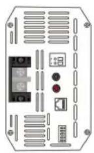
natural_image
Front view of a device chassis with labeled ports and connectors (no readable text or symbols)text_image
205,0 mm 145,0 mm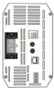
natural_image
Front view of a computer interface panel with buttons and ports (no visible text or labels)natural_image
Front view of an electronic device casing with ports, buttons, and wiring (no visible text or symbols)natural_image
Coiled white cable with black handle, isolated on white background (no text or symbols)natural_image
Diagram of a computer interface with a pencil inserted, showing a curved arrow indicating rotation (no text or symbols present)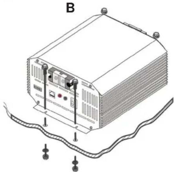
natural_image
Line drawing of a server rack with attached components and wiring (no text or symbols)natural_image
Technical diagram of a mechanical component with mounting holes and a central housing (no text or symbols)2
natural_image
Diagram of an electronic device showing a connector with pins and a red cross symbol (no text or labels)3 im Uhrzeigersinn
natural_image
Technical diagram of an electronic device with screw and housing components, no visible text or symbolsD+ Zündverkabelung
line
| °C | ln | | --- | ---- | | -5.0 | 0.4 | | 25 | 0 | | 50 | -0.6 |Hersteller: Shanghaimuxinmuyeyouxiangongsi
Adresse: Shuangchenglu 803nong11hao1602A-1609shi, Baoshanqu, Shanghai 200000 CN.
YH CONSULTING LIMITED. C/O YH Consulting
Limited, Büro 147, Centurion House, London
Road, Staines-upon-Thames, Surrey, TW18 4AX
| EG-Vertreter |
E-CrossStu GmbH
Mainzer Landstr.69,
60329 Frankfurt am Main.

www.vevor.com/support
VEVOR
Affordable. Reliable. Home Improvement.
CARICABATTERIE DC-DC
MODELLO:SDC-20A, SDC-30A, SDC-40A, SDC-60A
Affordable. Reliable. Home Improvement.
BATTERIA CC-CC
CARICABATTERIE
MODELLO:SDC-20A, SDC-30A, SDC-40A, SDC-60A
natural_image
Top-down view of a black rectangular electronic device with orange connectors and labeled pins (no text or symbols on the device itself)text_image
165,0mm 145,0mm
natural_image
Front view of a device chassis with labeled ports and ventilation slots (no readable text or symbols)text_image
205,0mm 145,0mm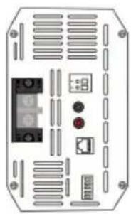
natural_image
Front view of an electronic device chassis with ports and connectors (no visible text or symbols)text_image
83,0mm 240,0mm 145,0mmnatural_image
Coiled white cable with black end cap, isolated on white background (no text or symbols)natural_image
Technical diagram of a mechanical component with mounting holes and a central housing (no text or symbols)2
natural_image
Diagram of an electronic device showing a connector with pins and a red cross symbol (no text or labels)3 in senso orario
natural_image
Technical diagram of an electronic device with screw and housing components, no visible text or symbolsImportato in AUS: SIHAO PTY LTD. 1 ROKEVA STREETEASTWOOD
Nuovo Galles del Sud 2122 Australia
Importato negli USA: Sanven Technology Ltd. Suite 250, 9166 Anaheim Place, Rancho Cucamonga, CA 91730
| RAPPRESENTANZA DEL REGNO UNITO |
YH CONSULTING LIMITED. C/O YH Consulting Limited Ufficio 147, Centurion House, London Road, Staines-upon-Thames, Surrey, TW18 4AX
E-CrossStu GmbH
Via Magonza 69,
Affordable. Reliable. Home Improvement.
Affordable. Reliable. Home Improvement.
BATERÍA CC-CC
CARGADOR
MODELO: SDC-20A, SDC-30A, SDC-40A, SDC-60A
natural_image
Top-down view of a black rectangular electronic device with orange connectors and labeled pins (no text or symbols on the device itself)text_image
165,0 mm 145,0 mm
natural_image
Front view of a device chassis with labeled ports and ventilation slots (no readable text or symbols)text_image
205,0 mm 145,0 mm
natural_image
Front view of an electronic device chassis with ports and connectors (no visible text or symbols)natural_image
Front view of an electronic device casing with ports, buttons, and wiring (no visible text or symbols)natural_image
Coiled white cable with black end cap, isolated on white background (no text or symbols)natural_image
Diagram of a computer monitor with a pencil inserted, showing a curved arrow indicating rotation (no text or symbols present)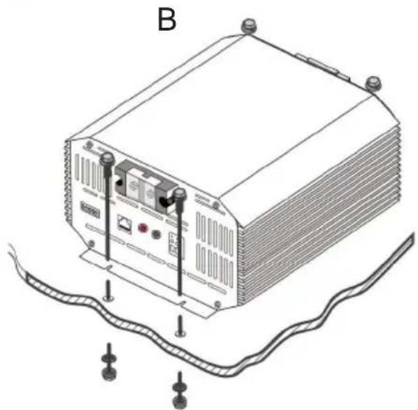
natural_image
Technical line drawing of a rectangular electronic device with mounting points and wiring, labeled 'B' (no text or symbols on the device itself)Cableado y fusibles
natural_image
Technical diagram of a mechanical component with mounting holes and a central housing (no text or symbols)2
natural_image
Technical diagram of an electronic device showing a connector with pins and a red cross symbol (no text or labels)3 dextrorso
natural_image
Technical diagram of an electronic device with screw and housing components, no visible text or symbolschemical
Diagram of a circular DNA structure with labeled segments and directional arrows indicating electron flow or binding
line
| °C | En | | --- | ---- | | -5 | 0.4 | | 25 | 0 | | 50 | -0.6 |Fabricante: Shanghaimuxinmuyeyouxiangongsi
Dirección: Shuangchenglu 803nong11hao1602A-1609shi, baoshanqu, shanghai 200000 CN.
Importado a AUS: SIHAO PTY LTD. 1 ROKEVA STREET, EASTWOOD NSW 2122 Australia
Importado a EE. UU.: Sanven Technology Ltd. Suite 250, 9166 Anaheim Place, Rancho Cucamonga, CA 91730
text_image
REPRESENTANTE DEL REINO UNIDOYH CONSULTING LIMITADA. A/C YH Consulting
Limited Oficina 147, Centurion House, London
Road, Staines-upon-Thames, Surrey, TW18 4AX
text_image
Representante del CEE-CrossStu GmbH
Mainzer Landstr.69,
Affordable. Reliable. Home Improvement.
ŁADOWARKA AKUMULATORÓW DC-DC
MODEL: SDC-20A, SDC-30A, SDC-40A, SDC-60A
Affordable. Reliable. Home Improvement.
AKUMULATOR DC-DC
RUMAK
MODEL: SDC-20A, SDC-30A, SDC-40A, SDC-60A
natural_image
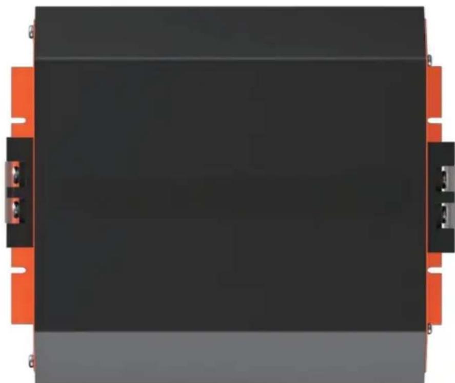
Top-down view of a black rectangular electronic device with orange connectors and mounting holes (no text or symbols visible)text_image
165,0 mm 145,0 mm
natural_image
Front view of a device chassis with labeled ports and ventilation slots (no readable text or symbols)text_image
205,0 mm 145,0 mm
natural_image
Front view of an electronic device casing with ports and indicator lights (no text or symbols visible)natural_image
Front view of an electronic device casing with ports, buttons, and wiring (no visible text or symbols)natural_image
Coiled white cable with black handle, isolated on white background (no text or symbols)natural_image
Diagram of a computer monitor with a pencil inserted, showing a curved arrow indicating rotation (no text or symbols present)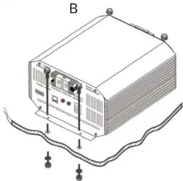
natural_image
Line drawing of a server rack with attached components and wiring (no text or symbols)natural_image
Technical diagram of a mechanical or electronic component with mounting holes and a central switch (no text or symbols)2
natural_image
Technical diagram of an electronic device showing a connector with pins and a red cross symbol (no text or labels)3 zgodnje zo wokzodnikami zagoro
natural_image
Technical diagram of an electronic device showing a central switch, screw holes, and a red cross symbol (no text or labels)text_image
Diagram of a device rear panel with labeled ports and connection to a bus, showing D+ signal directiontext_image
Diagram of an electronic device rear panel with labeled ports and connections to a bus, including 'LC+' and 'D+' labels.Działanie
line
| °C | w | | --- | ---- | | -5.0 | 0.4 | | 25 | 0.0 | | 50 | -0.6 |Producent: Shanghaimuxinmuyeyouxiangongsi Adres:
Shuangchenglu 803nong11hao1602A-1609shi, Baoshanqu, Szanghaj 200000 CN.
Importowane do AUS: SIHAO PTY LTD. 1 ROKEVA STREETEASTWOOD NSW 2122 Australia
Importowane do USA: Sanven Technology Ltd. Suite 250, 9166 Anaheim Place, Rancho Cucamonga, CA 91730
| REP WIELKIEJ BRYTANII |
| Przedstawiciel UE |
YH CONSULTING LIMITED. C/O YH Consulting Limited
Biuro 147, Centurion House, London Road, Staines-upon-Thames, Surrey, TW18 4AX
E-CrossStu GmbH
Mainzer Landstr.69,
60329 Frankfurt nad Menem.

Affordable. Reliable. Home Improvement.
DC-DC BATTERIJLADER
MODEL: SDC-20A, SDC-30A, SDC-40A, SDC-60A
Technische ondersteuning en e-garantiecertificaat www.vevor.com/support
VEVOR
Affordable. Reliable. Home Improvement.
DC-DC-BATTERIJ
OPLADER
MODEL: SDC-20A, SDC-30A, SDC-40A, SDC-60A
natural_image
Top-down view of a black rectangular electronic device with orange connectors and labeled pins (no text or symbols on the device itself)Lithium-activering 18
Probleemoplossing 19
Onderhoud 21
Technische specificaties 22
text_image
165,0 mm 145,0 mm
natural_image
Front view of a device chassis with labeled ports and connectors (no readable text or symbols)text_image
205,0 mm 145,0 mm
natural_image
Front view of a computer interface panel with buttons and ports (no visible text or labels)natural_image
Front view of an electronic device casing with ports, buttons, and wiring (no visible text or symbols)natural_image
Coiled white cable with black handle, isolated on white background (no text or symbols)natural_image
Diagram of a computer monitor with a pencil inserted, showing a scroll and cable stack (no text or symbols)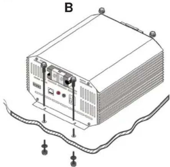
natural_image
Line drawing of a server rack with attached components and wiring (no text or symbols)natural_image
Technical diagram of a mechanical or electronic component with mounting holes and a central switch (no text or symbols)2
natural_image
Diagram of an electronic device showing a connector with pins and a red cross symbol (no text or labels)3 rechtsom
natural_image
Technical diagram of an electronic device with screw and housing components, no visible text or symbolsD+ Ontstekingsbedrading
text_image
Diagram of an electronic device rear panel with labeled ports and connections to a bus, showing connections via LC+ and D+ cables.18-16AWG,
line
| Phase | Current (I) | Voltage (U0 IN) | |-------------|-------------|-----------------| | Absorptie | 100% | U0 IN | | Vlot | 10% | IN |Bulk (fase I) (loodzuur + lithium)
YH CONSULTING LIMITED. C/O YH Consulting
Limited Kantoor 147, Centurion House, London
Road, Staines-upon-Thames, Surrey, TW18 4AX
text_image
EC-REPE-CrossStu GmbH
Mainzer Landstr.69,
60329 Frankfurt am Main.

Technische ondersteuning en e-garantiecertificaat www.vevor.com/support
VEVOR
Affordable. Reliable. Home Improvement.
DC-DC BATTERILADDARE
MODELL: SDC-20A, SDC-30A, SDC-40A, SDC-60A
Affordable. Reliable. Home Improvement.
DC-DC BATTERI
LADDARE
MODELL: SDC-20A, SDC-30A, SDC-40A, SDC-60A
natural_image
Top-down view of a black rectangular electronic component with orange connectors on both sides (no text or symbols visible)text_image
165,0 mm 145,0 mm
natural_image
Front view of a device chassis with labeled ports and ventilation slots (no readable text or symbols)text_image
205,0 mm 145,0 mm
natural_image
Front view of an electronic device chassis with ports and connectors (no visible text or symbols)natural_image
Front view of an electronic device casing with ports, buttons, and wiring (no visible text or symbols)natural_image
Coiled white cable with black handle, isolated on white background (no text or symbols)natural_image
Diagram of a computer monitor with a pencil inserted, showing a scroll and cable stack (no text or symbols)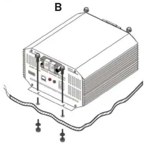
natural_image
Line drawing of an electronic device labeled 'B' connected to a wavy cable, with no visible text or symbols beyond the label.natural_image
Line drawing of a server rack with ports and connectors (no text or symbols)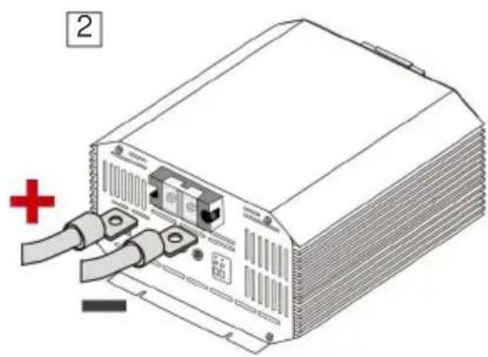
natural_image
Illustration of a server rack with two cables and a red plus symbol (no text or labels)3 medurs
natural_image
Illustration of an electronic device with ports and a red plus symbol indicating polarity (no text or labels)natural_image
Technical diagram of a mechanical or electronic component with mounting holes and a central housing (no text or symbols visible)2
natural_image
Diagram of an electronic device showing a connector with pins and a red cross symbol (no text or labels)3 medurs
natural_image
Technical diagram of an electronic device with screw and housing components, no visible text or symbolsD+ tändkabel
text_image
Diagram of an electronic device rear panel with labeled ports and connections to a bus, showing connections via LC+ and D+ cables.18-16AWG,
kopparkabel rekommenderas
Drift
Bulk (fas I) (blysyra + litium)
Absorption (Fas U0) (blysyra + litium)
line
| °C | I | | --- | ---- | | -50 | 0.4 | | 25 | 0 | | 50 | -0.6 |Tillverkare: Shanghaimuxinmuyeyouxiangongsi
Adress: Shuangchenglu 803nong11hao1602A-1609shi, baoshanqu, shanghai 200000 CN.
Importerad till AUS: SIHAO PTY LTD. 1 ROKEVA STREETEASTWOOD NSW 2122 Australien
Importerad till USA: Sanven Technology Ltd. Suite 250, 9166 Anaheim Place, Rancho Cucamonga, CA 91730
| UK | REP |
YH CONSULTING LIMITED. C/O YH Consulting
Limited Office 147, Centurion House, London
Road, Staines-upon-Thames, Surrey, TW18 4AX
| EC | REP |
E-CrossStu GmbH
Mainzer Landstr.69,
60329 Frankfurt am Main.

www.vevor.com/support