SCWP80Ⅱ - Water pump Vevor - Free user manual and instructions
Find the device manual for free SCWP80Ⅱ Vevor in PDF.

| Brand | Vevor |
| Model | SCWP80-II |
| Product Type | Gasoline Engine Water Pump |
| Suction Port Diameter | 80 mm |
| Discharge Port Diameter | 80 mm |
| Max Flow Rate | 60 m³/h |
| Total Head | 43 m |
| Max Suction Height | 7 m |
| Engine | SV210, 209 cc, 3600 rpm |
| Fuel Type | Unleaded gasoline (octane rating 86+) |
| Fuel Tank Capacity | Not specified (fill to filter shoulder) |
| Engine Lubrication | 4-stroke engine oil, SAE appropriate for temperature |
| Ignition | Spark plug F7RTC, gap 0.70–0.80 mm |
| Main Functions | Pumping non-potable fresh water, self-priming |
| Routine Maintenance | Check oil, air filter, spark plug, oil change (first 20h, then every 100h) |
| Safety | Emergency stop, avoid CO, do not pump flammable liquids, flat surface |
| Spare Parts | Available from authorized dealer |
| Warranty | Electronic warranty certificate at www.vevor.com/support |
| Weight | Approximately 35 kg (estimate) |
Frequently Asked Questions - SCWP80Ⅱ Vevor
User questions about SCWP80Ⅱ Vevor
0 question about this device. Answer the ones you know or ask your own.
Ask a new question about this device
Download the instructions for your Water pump in PDF format for free! Find your manual SCWP80Ⅱ - Vevor and take your electronic device back in hand. On this page are published all the documents necessary for the use of your device. SCWP80Ⅱ by Vevor.
USER MANUAL SCWP80Ⅱ Vevor
Support and E-Warranty Certificate https://www.vevor.com/support
WATER PUMP
USR MANUAL
MODEL:SCWP80-II/SCWP50
We continue to be committed to provide you tools with competitive price. "Save Half", "Half Price" or any other similar expressions used by us only represents an estimate of savings you might benefit from buying certain tools with us compared to the major top brands and does not necessarily mean to cover all categories of tools offered by us. You are kindly reminded to verify carefully when you are placing an order with us if you are actually saving half in comparison with the top major brands.
Model:SCWP80-II/SCWP50
NEED HELP? CONTACT US!
Have product questions? Need technical support? Please feel free to contact us:
Technical Support and E-Warranty Certificate
www.vevor.com/support
This is the original instruction. Please read all manual instructions carefully before operating. VEVOR reserves a clear interpretation of o user manual. The appearance of the product shall be subject to the product you received. Please forgive us that we won't inform you ag there are any technology or software updates on our product.
PUMP SAFETY
Your safety and the safety of others are very important. And using the water pump safely is an important responsibility.
To help you make informed decisions about safety, we have provided operating procedures and other information on labels and in this manu. This information alerts you to potential hazards that could hurt you or others.
Of course, it is not practical or possible to warn you about all the I associated with operating or maintaining a water pump. You must use own good judgment.
You will find important safety information in a variety of forms, includi
Safety Labels-on the pump.
Safety Messages—preceded by a safety alert symbol and one of three signal words, DANGER, WARNING, or CAUTION. These signal words mean:

You WILL be KILLED or SERIOUSLY HURT if you don't f instructions.

You CAN be KILLED or SERIOUSLY HURT if you don't for instructions.

You CAN be HURT if you don't follow instructions.

Your pump or other property could be damaged if you don't follow instructions.
Safety Headings—such as IMPORTANT SAFETY INFORMATION.
Safety Section—such as PUMP SAFETY.
Instructions—how to use this pump correctly and safely.
This entire book is filled with important safety information—please read carefully.
Always make a preoperation inspection before you start the engine. Y may prevent an accident or equipment damage.
Most accidents can be prevented if you follow all instructions in this and on the pump. The most common hazards are discussed below, a with the best way to protect yourself and others.
Operator Responsibility
It is the operator's responsibility to provide the necessary safeguards to protect people and property. Know how to stop the pump quickly in an emergency. If you leave the pump for any reason, always turn the engine off. Understand the use of all controls and connections.
Be sure that anyone who operates the pump receives proper instruction. Do not let children operate the pump. Keep children and pets away the area of operation.
Pump Operation
Pump only water that is not intended for human consumption. Pumping is flammable liquids, such as gasoline or fuel oils, can result in a fire or explosion, causing serious injury. Pumping seawater, beverages, acids, chemical solutions, or any other liquid that promotes corrosion can damage the pump.
Refuel With Care
Gasoline is extremely flammable, and gasoline vapor can explode. Refractory outdoors, in a well-ventilated area, with the engine stopped and the power on a level surface. Do not fill the fuel tank above the fuel strainer since Never smoke near gasoline, and keep other flames and sparks away.
Always store gasoline in an approved container. Make sure that any fuel has been wiped up before starting the engine. After refueling, measure the tank cap is closed properly and securely.
Hot Exhaust
The muffler becomes very hot during operation and remains hot for a.
after stopping the engine. Be careful not to touch the muffler while it
Let the engine cool before transporting the pump or storing it indoors
To prevent fire hazards, keep the pump at least 3 feet(1 meter)away building walls and other equipment during operation. Do not place flammable objects close to the engine..
Carbon Monoxide Hazard
Exhaust gas contains poisonous carbon monoxide. Avoid inhalation of exhaust gas. Never run the engine in a closed garage or confined a
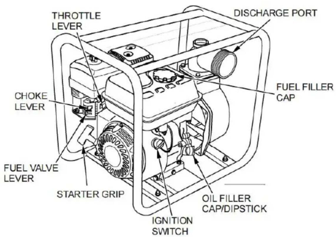
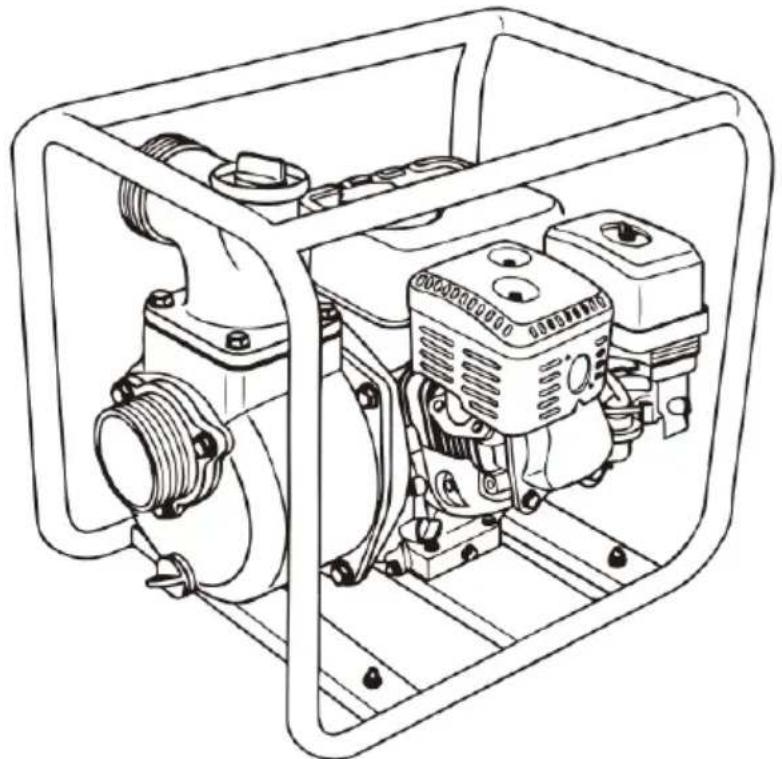
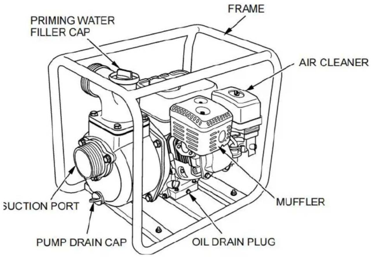
COMPONENTS & CONTROL LOCATIONS
CONTROLS
Read and understand this manual. Know what the controls do and how to operate them.
Familiarize yourself with the pump and its operation before you begin pumping. Know what to do in case of emergencies.
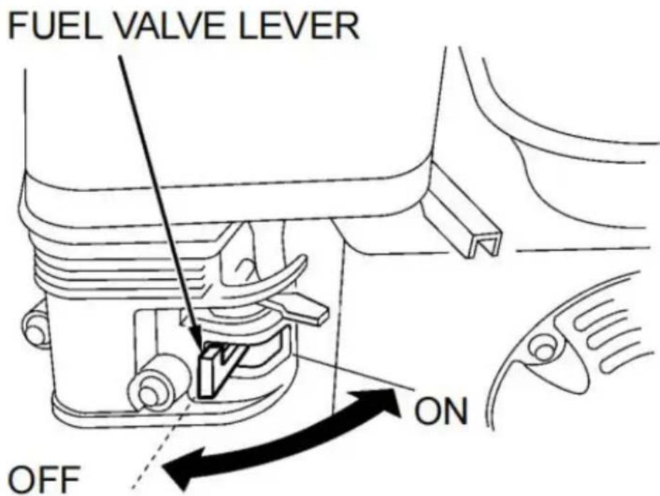
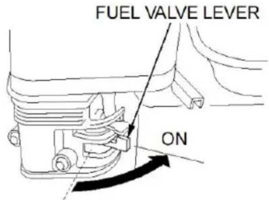
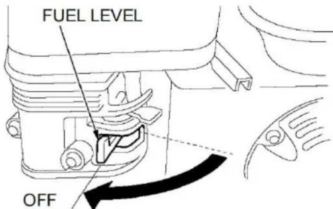
Fuel Valve Lever
The fuel valve opens and closes the passage between the fuel tank the carburetor.
The fuel valve lever must be in the ON position for the engine to run. When the engine is not in use, leave the fuel valve lever in the OFF position to prevent carburetor flooding and reduce the possibility of fuel leakage.
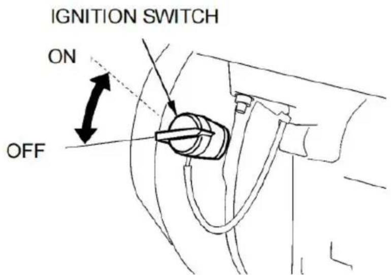
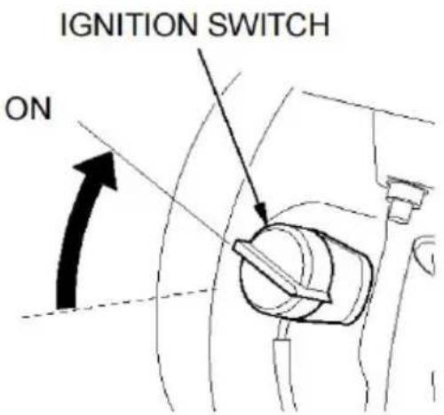
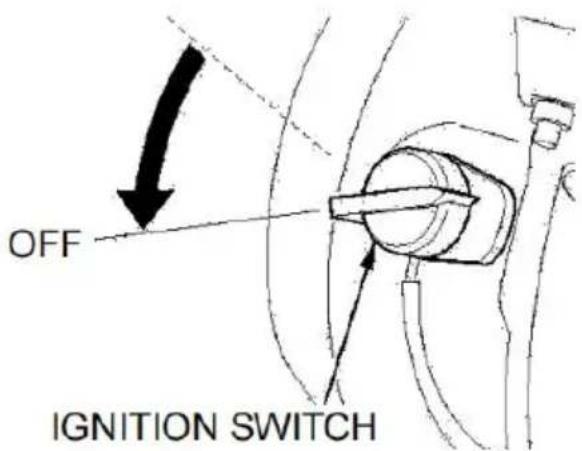
Ignition Switch
The ignition switch controls the ignition system.
The ignition switch must be in the ON position for the engine to run. Turning the ignition switch to the OFF position stops the engine.
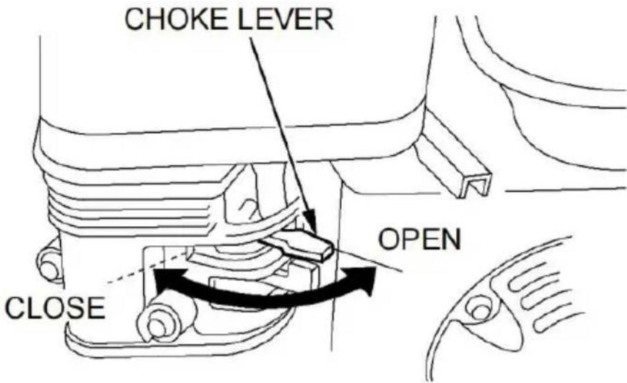
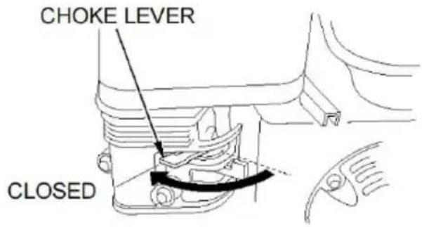
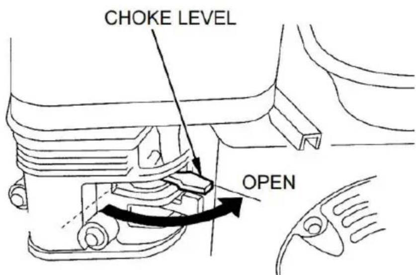
Choke Lever
The choke lever opens and closes the choke valve in the carburetor.
CLOSED position enriches the fuel mixture for starting a cold engine. The OPEN position provides the correct fuel mixture for operation after starting and for restarting a warm engine.
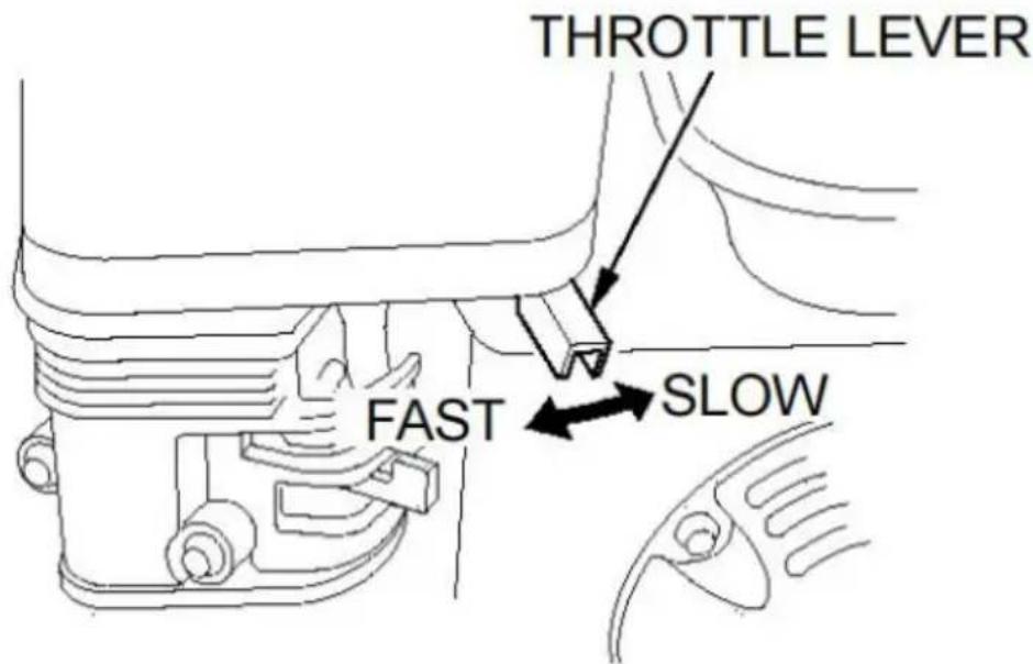
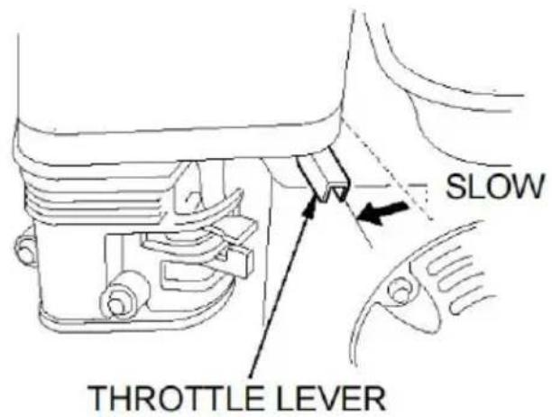
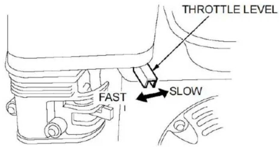
Throttle Lever
The throttle lever controls engine speed.
Moving the throttle lever in the directions shown makes the engine run faster or slower.
The pump output is controlled by adjusting the throttle lever. At the maximum throttle position, the pump will deliver the highest output vol Moving the throttle lever toward the idle position will decrease the ou volume of the pump.
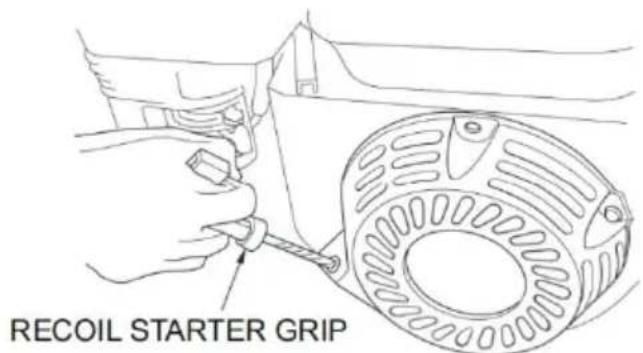
Recoil Starter Grip
Pulling the recoil starter grip operates the recoil starter to crank the

Be sure of what you are pumping. This pump is designed to pump fresh water that is not intended for human consumption.
For your safety and to maximize the service life of your equipment, I very important to take a few moments before you operate the pump check its condition. Be sure to take care of any problem you find on your servicing dealer correct it before you operate the pump.
WARNING
Improperly maintaining this pump, or failing to correct a problem before operation, could cause a malfunction in which you could be seriously injured. Always perform a preoperation inspection before each operation, and correct any problem.
Exhaust gas contains poisonous carbon monoxide. Avoid inhalation of exhaust gas. Never run the engine in a closed garage or confined a
To prevent fire hazards, keep the pump at least 3 feet(1 meter) away
building walls and other equipment during operation. Do not place flammable objects close to the engine.
Before beginning your preoperation checks, be sure the pump is on at a Surface, and the ignition switch is in the OFF position.
Check the General Condition of the Pump
Look around and underneath the pump for signs of oil or gasoline le Remove any excessive dirt or debris, especially around the engine mu and recoil starter.
Look for signs of damage.
Check that all nuts, bolts, screws, hose connectors, and clamps are tightened.
Check the Suction and Discharge Hoses
Check the general condition of the hoses. Be sure the hoses are in serviceable condition before connecting them to the pump. Remember the suction hose must be reinforced construction to prevent hose colla
Check that the sealing washer in the suction hose connector is in good condition (see page 14).
Check that the hose connectors and clamps are securely installed (se pages 14&15).
Check that the strainer is in good condition and is installed on the hose (see page 14).
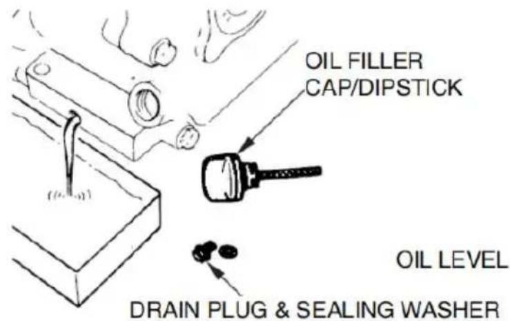
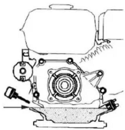
CHECK ENGINE OIL LEVEL
Check the engine oil level with the engine stopped and in a level pot. 1.Remove the oil filler cap/dipstick and wipe it clean.
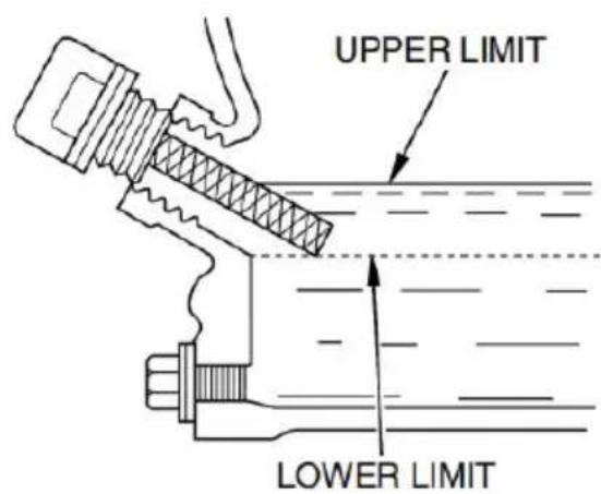
2.Insert and remove the dipstick without screwing it into the filler neck. Check the oil level shown on the dipstick.
3.If the oil level is low, fill the edge of the oil filler hole with the recommended oil (see page 24).
4.Screw in the oil filler cap/dipstick securely.
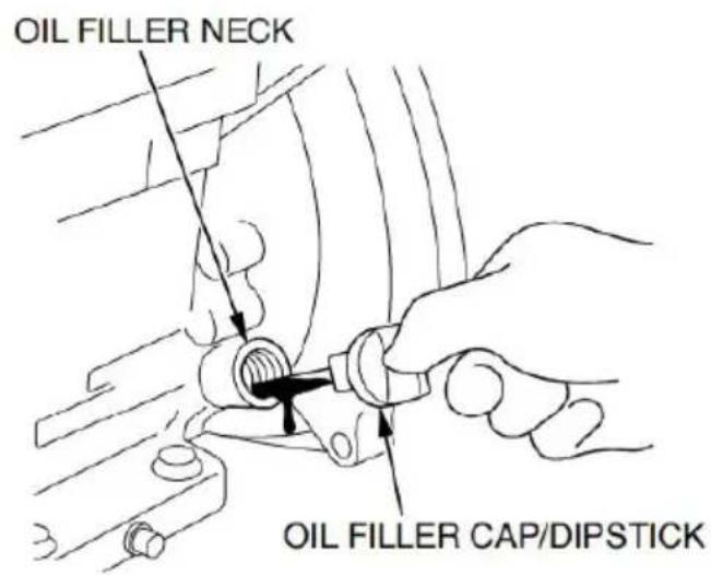

Running the engine with a low oil level can cause engine damage.
AIR FILTER INSPECTION
A dirty air filter will restrict airflow to the carburetor, reducing engine pump performance.
Remove the air cleaner cover and inspect the filter. Clean or replace filter elements. Always replace damaged filter elements. If equipped with an oil-bath air cleaner, also check the oil level.
Reinstall the air filter and air cleaner cover. Be sure all the parts sh below are in place. Tighten the wing nut securely.
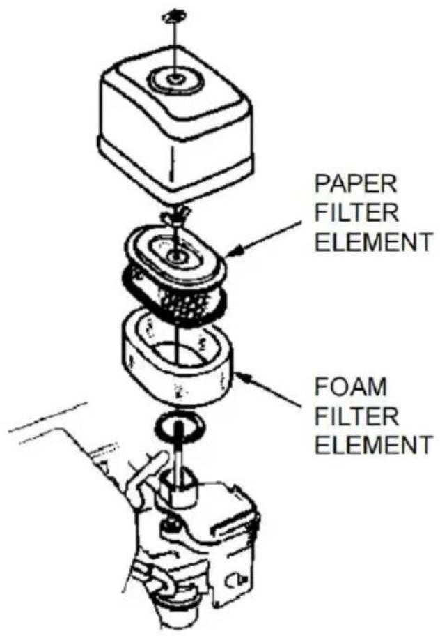
NOTI Operating the engine without an air filter or with a damage air filter will allow dirt to enter the engine, causing rapid engine wear. This type of damage is not covered by the Distributor's Limited Warranty.
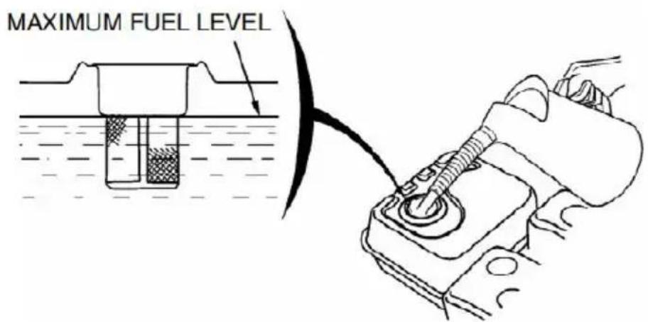
CHECK FUEL LEVEL
With the engine stopped and on a level surface, remove the fuel tank and check the fuel level. Refill the tank if the fuel level is low. After tightening the fuel tank cap securely.
WARNING Gasoline is highly flammable and explosive. You can be burned or seriously injured when handling fuel.
-
Stop the engine and keep heat, sparks, and flame away.
-
Handle fuel only outdoors.
Wipe up spills immediately.
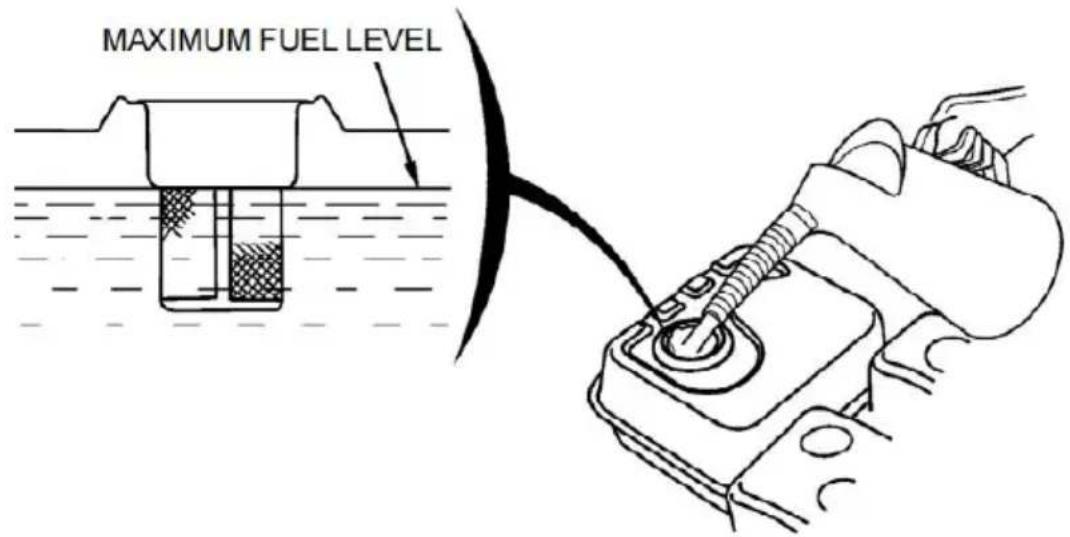
N o T I D o not fill above the shoulder of the fuel strainer(maximum level).
FUEL RECOMMENDATIONS
Use unleaded gasoline with a pump octane rating of 86 or higher. These engines are certified to operate on unleaded gasoline. Unleaded gasoline produces fewer engine and spark plug deposits and extends exhaust system life.
Never use stale or contaminated gasoline or an oil/gasoline mixture. A getting dirt or water in the fuel tank.
Occasionally you may hear a light "spark knock" or "pinging" (metallic rapping noise) while operating under heavy loads. This is no cause for concern.
If a spark knock or pinging occurs at a steady engine speed, under load, change brands of gasoline. If spark knock or pinging persists, authorized servicing dealer.
Running the engine with persistent spark knock or ping
can cause engine damage.
Running the engine with persistent spark knock or pinging is mis and the Distributor's Limited Warranty does not cover parts damage by misuse.
OPERATION
SAFE OPERATING PRECAUTIONS
To safely realize the full potential of this pump, you need a complete understanding of its operation and a certain amount of practice with i controls.
Before operating the pump for the first time, please review the
IMPORTANT SAFETY INFORMATION on page 3 and the chapter titles CHECK BEFORE OPERATION.
For your safety, avoid starting or operating the engine in an enclosed such as a garage. Your engine's exhaust contains poisonous carbon monoxide gas, which can collect rapidly in an enclosed area and cause illness or death.
Pump only fresh water that is not intended for human consumption.
Pumping flammable liquids, such as gasoline or fuel oils, can result in or explosion, causing serious injury. Pumping seawater, beverages, acid chemical solutions, or any other liquid that promotes corrosion can da the pump.
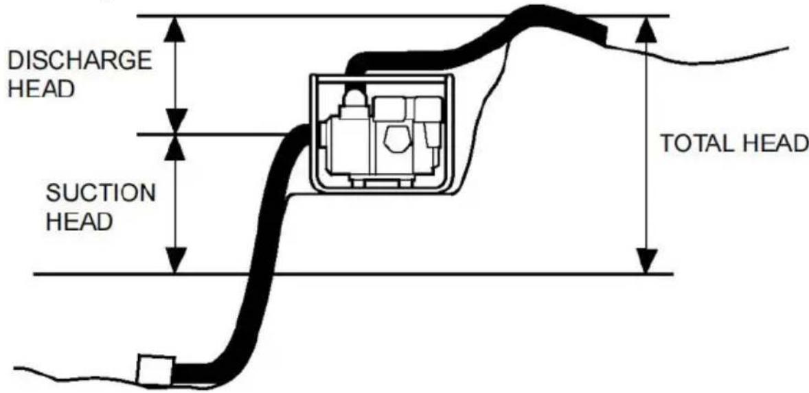
PUMP PLACEMENT
For best pump performance, place the pump near the water level, and hoses that are no longer than necessary. That will enable the pump to produce the greatest output with the least self-priming time.
As the head (pumping height) increases, pump output decreases. The length, type, and size of the suction and discharge hoses can also
significantly affect pump output.
Discharge head capability is always greater than suction head capability so it is important for the suction head to be the shorter part of the head.
Minimizing the suction head (placing the pump near the water level) is very important for reducing self-priming time. Self-priming time is the time that it takes the pump to bring water the distance of the suction head to the initial operation.
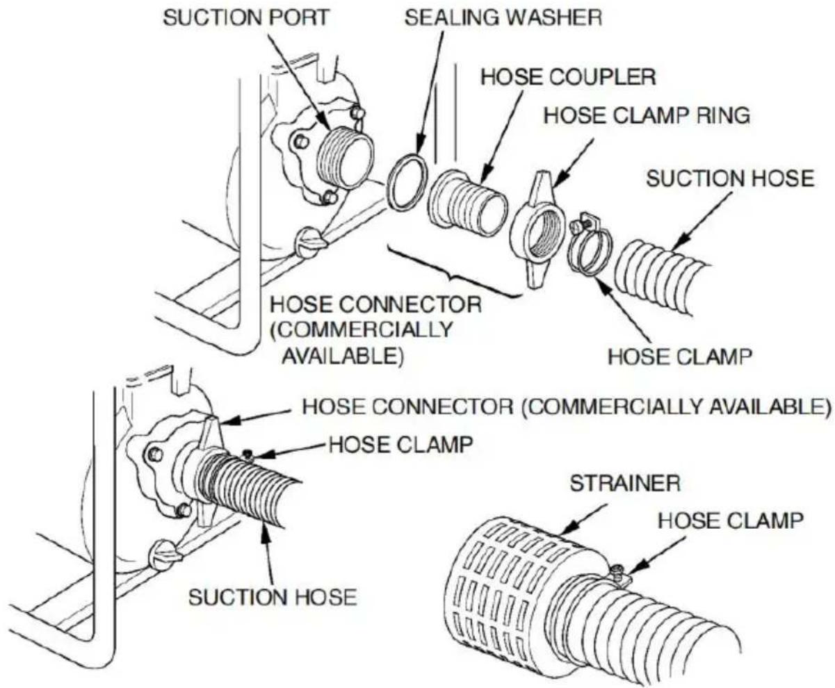
SUCTION HOSE INSTALLATION
Use a commercially available hose and hose connector with the hose clamp provided with the pump. The suction hose must be reinforced non-collapsible wall or braided wire construction.
Do not use a hose smaller than the pump's suction port size. Minimise hose size: WP25 (25mm), SCWP50, WP50, CP50, HP50 (50mm), WTB, SCWP80-II, WP80 (80mm), WP100 (100mm).
The suction hose should be no longer than necessary. Pump performance is best when the pump is near the water leve, and the hoses are set. Use a hose clamp to securely fasten the hose connector to the suction hose in order to prevent air leakage and loss of suction. Verify that the hose connector sealing washer is in good condition.
Install the strainer (provided with the pump) on the other end of the hose, and secure it with a hose clamp. The strainer will help to pre
pump from becoming clogged or damaged by debris.
Securely tighten the hose connector on the pump suction port.
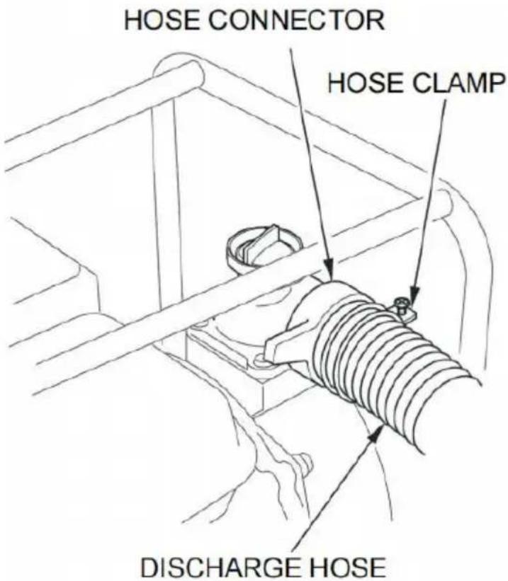
DISCHARGE HOSE INSTALLATION
Use a commercially available hose and hose connector and clamp provided with the pump.
It is best to use a short, large-diameter hose because that will reduce friction and improve pump output. A long or small-diameter hose will increase fluid friction and reduce pump output.
Tighten the hose clamp securely to prevent the discharge hose from disconnecting under pressure.
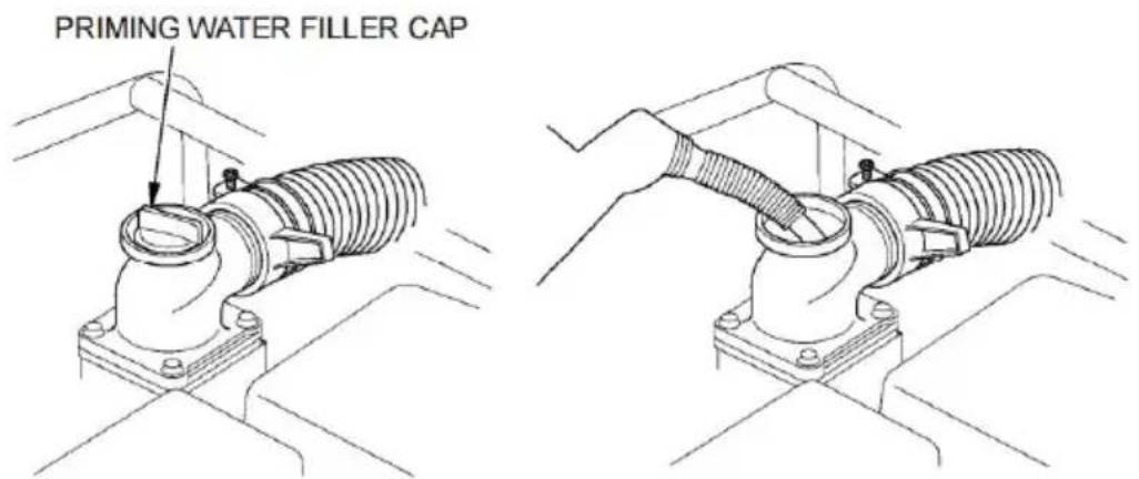
PRIMING THE PUMP
Before starting the engine, remove the filler cap from the pump char and completely fill the pump chamber with water. Reinstall the filler c and tighten it securely.
NOTICE
Operating the pump dry will destroy the pump seal. If the pump has been operated dry, stop the engine immediately and allow the pump to cool before priming.
STARTING THE ENGINE
- Prime the pump(see page 16).
- Move the fuel valve lever to the ON position.
3.To start a cold engine, move the choke lever to the CLOSED position; restart a warm engine, leave the choke lever in the OPEN position.
- Move the throttle lever away from the SLOW position about 1/3 of way toward the FAST position.
- Turn the ignition switch to the ON position.
6.Pull the recoil starter grip lightly until resistance is felt, then pull it. Do not allow the recoil starter grip to snap back against the engine. Return it gently to prevent damage to the starter.
7.If the choke lever was moved to the CLOSED position to start the gradually move it to the OPEN position as the engine warms up.
8.Setting engine speed
After starting the engine, move the throttle lever to the FAST position self-priming, and check the pump output.
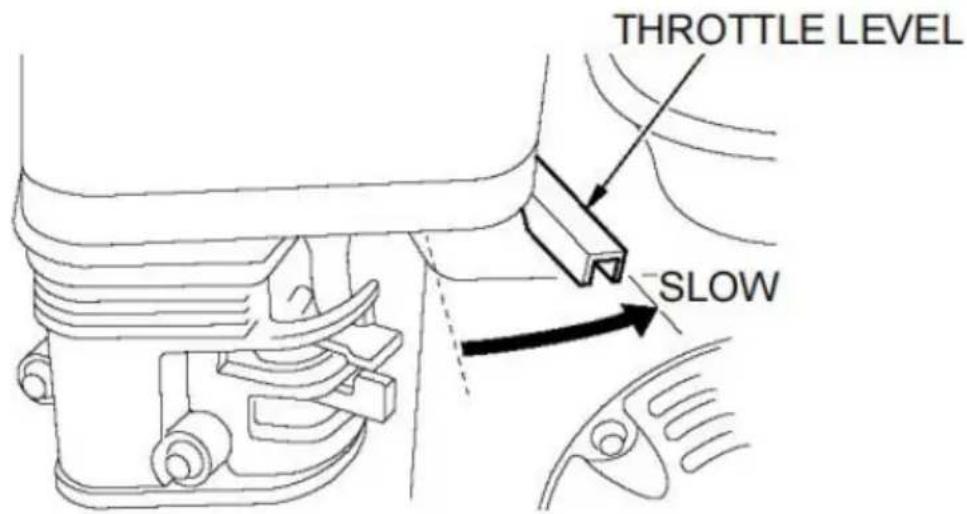
The pump output is controlled by adjusting the engine speed. Moving throttle lever in the FAST direction will increase pump output, and more the throttle lever in the SLOW direction will decrease pump output.
STOPPING THE ENGINE
To stop the engine in an emergency, simply turn the ignition switch OFF position. Under normal conditions, use the following procedure.
- Move the throttle lever to the SLOW position.
- Turn the ignition switch to the OFF position.
- Turn the fuel valve lever to the OFF position.
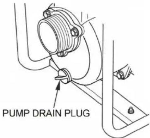
After use, remove the pump drain plug(see page 31), and drain the chamber. Remove the filler cap, and flush the pump chamber with clear fresh water. Allow the water to drain from the pump chamber, then run the filler cap and drain plug.
MAITENANCE
THE IMPORTANCE OF MAINTENANCE
Good maintenance is essential for safe, economical, and trouble-free operation. It will also help reduce air pollution.
WARNING
Improperly maintaining this pump, or failing to correct a
problem before operation, can cause a malfunction in which you can seriously hurt or killed.
Always follow the inspection and maintenance recommendations and schedules in this owner's manual.
To help you properly care for your pump, the following pages include maintenance schedule, routine inspection procedures, and simple maintenance procedures using basic hand tools. Other service tasks that are more difficult, or require special tools, are best handled by professionals and are normally performed by a technician or other qualified mechanic.
The maintenance schedule applies to normal operating conditions. If you operate your pump under severe conditions, such as sustained high-loss or high-temperature operation, or use it in unusually wet or dusty conditions, consult your servicing dealer for recommendations applicable to your individual needs and use.
Remember that your servicing dealer knows your pump best and is fine equipped to maintain and repair it.
To ensure the best quality and reliability, use only new, genuine parts their equivalents for repair and replacement.
Maintenance, replacement, or repair of emission control devices and systems may be performed by any engine repair establishment or
individual, using parts that are "certified" to EPA standards. MAINTENANCE SAFETY
Some of the most important safety precautions follow. However, we can warn you of every conceivable hazard that can arise in performing maintenance. Only you can decide whether or not you should perform given task.
WARNING
Failing to properly follow maintenance instructions and
precautions can cause you to be seriously hurt or killed.
Always follow the procedures and precautions in the owner's mar
Safety Precautions
Make sure the engine is off before you begin any maintenance or re. This will eliminate several potential hazards:
-Carbon monoxide poisoning from engine exhaust.
Be sure there is adequate ventilation whenever you operate the engine. -Burns from hot parts.
Let the engine and exhaust system cool before touching.
-Injury from moving parts.
Do not run the engine unless instructed to do so.
Read the instructions before you begin, and make sure you have the and skills required.
To reduce the possibility of fire or explosion, be careful when working around gasoline. Use only a nonflammable solvent, not gasoline, to cl parts. Keep cigarettes, sparks, and flames away from all fuel-related p
MAINTENANCE SCHEDULE
| Performed at every indicated month or operating hour interv whichever comes first. | Each use | First month or 20 Hrs. | Every 3 months or 50 Hrs. | Every 6 months or 100 Hrs. | Every year o 300 Hrs. | |
| ITEM | ||||||
| •Engine oil | Check level | ○ | ||||
| Change | ○ | ○ | ||||
| •Air cleaner | Check | ○ | ||||
| Clean | ○(1) | |||||
| •Idle speed | Check-Adjust | ○(2) | ||||
| •Spark plug | Check-Clean | ○ | ||||
| •Spark arrester | Clean | ○ | ||||
| Combustion chamber | Clean | ○(2) | ||||
| •Valve clearance | Check-Adjust | ○(2) | ||||
| •Fuel tank and strain | Clean | ○(2) | ||||
| •Fuel tube | Check | Every 2 years (Replace if necessary) | ||||
| Impeller | Check | ○(2) | ||||
| Impeller clearance | Check | ○(2) | ||||
| Pump inlet valve | Check | ○(2) | ||||
Emission-related items.
(1)Service more frequently when used in dusty areas.
(2) These items should be serviced by your servicing dealer unless you have the proper tools and are mechanically proficient. Refer to the sh manual for service procedures.
REFUELING
With the engine stopped and on a level surface, remove the fuel tank and check the fuel level. Refill the tank if the fuel level is low.
Refuel in a well-ventilated area before starting the engine. If the engine has been running, allow it to cool. Refuel carefully to avoid spilling fuel. If fill the fuel tank above the fuel strainer shoulder. After refueling, tighten fuel tank cap securely.
Never refuel the engine inside a building where gasoline fumes may flames or sparks. Keep gasoline away from appliance pilot lights, barbecues, electric appliances, power tools, etc.
Spilled fuel is not only a fire hazard; it causes environmental damage up spills immediately.
NOTICE Do not fill above the shoulder of the fuel strainer (max fuel level).
Refuel in a well-ventilated area before starting the engine. If the engine has been running, allow it to cool. Refuel carefully to avoid spilling fuel. Do not fill the fuel tank above the fuel strainer shoulder. After refueling, tighten the fuel tank cap securely.
Never refuel the engine inside a building where gasoline fumes may
flames or sparks. Keep gasoline away from appliance pilot lights, barbecues, electric appliances, power tools, etc.
Spilled fuel is not only a fire hazard; it also causes environmental damage. Wipe up spills immediately.
NOTICE
Fuel can damage paint and plastic. Be careful not to
spill fuel when filling your fuel tank. Damage caused by spilled f not covered under warranty.
ENGINE OIL CHANGE
Drain the used oil while the engine is warm. Warm oil drains quickly completely.
- Place a suitable container below the engine to catch the used oil, then remove the oil filler cap/dipstick, drain plug, and sealing washer.
- Allow the used oil to drain completely, and then reinstall the drain and tighten it securely.
Please dispose of used motor oil in a manner that is compatible with the environment. We suggest you take used oil in a sealed container to local recycling center or service station for reclamation. Do not throw the trash; pour it on the ground or down a drain.
- With the engine in a level position, fill the outer edge of the oil fin with the recommended oil.
NOTICE
Running the engine with a low oil level can cause engine damage.
4.Screw in the oil filler cap/dipstick securely.
ENGINE OIL RECOMMENDATIONS
Oil is a major factor affecting performance and service life. Use 4-stro automotive detergent oil.
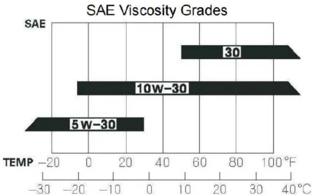
AMBIENT TEMPERATURE
The SAE oil viscosity and service classification are on the API label oil container. We recommend that you use API SERVICE category SJ The recommended operating range of this pump is 23^ F to 104^ F ( 5^
40^)
AIR FILTER CLEANING
A dirty air filter will restrict airflow to the carburetor, reducing engine performance. If you operate the pump in very dusty areas, clean the filter more frequently than specified in the MAINTENANCE SCHEDULE (see page 23).
- Clean the air filter in warm soapy water, rinse, and dry it thoroughly clean it in a nonflammable solvent and dry it thoroughly.
2.Dip the air filter in clean engine oil, and then squeeze out all excThe engine will smoke when started if too much oil is left in the fo
- Wipe dirt from the air cleaner base and cover using a moist rag. Be careful to prevent dirt from entering the air duct that leads to the car
SPARK PLUG SERVICE
Recommended spark plug: F7RTC or other equivalents.
NOTICE
Incorrect spark plugs can cause engine damage.
1.Disconnect the spark plug cap, and remove any dirt from around the spark plug area.
2.Remove the spark plug with a spark plug wrench.
3.Inspect the spark plug. Replace it if the electrodes are worn or if insulator is cracked or chipped.
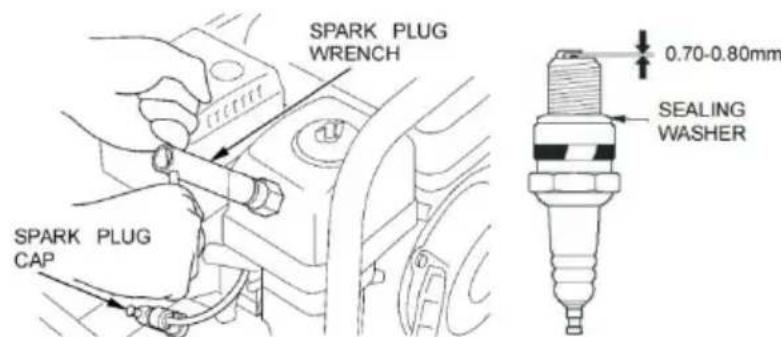
4.Measure the spark plug electrode gap with a suitable gauge. Correct gap, if necessary, by carefully bending the side electrode. The gap slit be 0.028-0.031 in (0.70-0.80mm).
5.Install the spark plug carefully, by hand, to avoid cross-threading.
6. After the spark plug seats, tighten with a spark plug wrench to corner the sealing washer.
If reinstalling the used spark plug, tighten 1/8-1/4 turn after the spa plug seats.
If installing a new spark plug, tighten 1/2 turn after the spark plug
NOTICE
A loose spark plug can overheat and damage the
engine. Over-tightening the spark plug can damage the threads in cylinder head.
- Attach the spark plug cap.
SPARK ARRESTER SERVICE (optional equipment)
Your engine is not factory-equipped with a spark arrester. In some areas is illegal to operate an engine without a spark arrester. Check local regulations. A spark arrester is available from authorized servicing dealers.
The spark arrester must be serviced every 100 hours to keep it func as designed.
If the engine has been running, the muffler will be very hot. Allow the muffler to cool before servicing the spark arrester.
1.Remove the two 8 mm nuts, and remove the muffler.
2.Remove the four 5 mm screws, and remove the muffler protector from the muffler.
3.Remove the 4 mm screw from the spark arrester, and remove the arrester from the muffler.
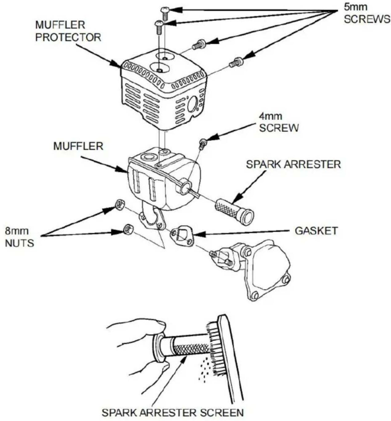
4.Use a brush to remove carbon deposits from the spark arrester scr Be careful to avoid damaging the screen.
The spark arrester must be free of breaks and holes. Replace the arrester if it is damaged.
5.Install the spark arrester, muffler protector, and muffler in the revers order of disassembly using a new gasket.
STORAGE/ TRANSPORTING
STORAGE PREPARATION
Proper storage preparation is essential for keeping your pump trouble-free and looking good. The following steps will help to keep rust and corrosion from impairing your pump's function and appearance and will make the engine easier to start when you use the pump again.
Cleaning
1.Wash the engine and pump.
Wash the engine by hand, and be careful to prevent water from entering the air cleaner or muffler opening. Keep water away from controls and other places that are difficult to dry, as water promotes rust.
NOTICE
- Using a garden hose or pressure washing equipment can force water into the air cleaner or muffler opening. Water in the air cleaner will soak the air filter, and water that passes through the filter or muffler can enter the cylinder, causing damage.
Water contacting a hot engine can cause damage. If the engine been running, allow it to cool for at least half an hour before washing.
2.Wipe dry on all accessible surfaces.
- Fill the pump chamber with clean, fresh water, start the engine oil and let it run until it reaches the normal operating temperature to ev any external water.
NOTICE
A dry operation will damage the pump seal. Be sumber is filled with water before starting the engine.
-
Stop the engine, and allow it to cool.
-
Remove the pump drain plug, and f pump with clean, fresh water. Allow the water to drain from the pump chamber, then reinstall the drain plug.
-
After the pump is clean and dry, to any damaged paint and coat areas that rust with a light film of oil. Lubricate c with a silicone spray lubricant.
Fuel
Gasoline will oxidize and deteriorate in storage. Old gasoline will cause hard starting, and it leaves gum deposits that clog the fuel system. If gasoline in your engine deteriorates during storage, you may need to replace the carburetor and other fuel system components serviced or replaced.
The length of time that gasoline can be left in your fuel tank and c without causing functional problems will vary with such factors as the gasoline blend, your storage temperatures, and whether the fuel tank partially or completely filled. The air in a partially filled fuel tank pron fuel deterioration. Very warm storage/temperatures accelerate fuel
deterioration. Fuel deterioration problems may occur within a few mont or even less if the gasoline was not fresh when you filled the fuel
The Distributor's Limited Warranty does not cover fuel system damage engine performance problems resulting from neglected storage preparation.
You can extend fuel storage life by adding a fuel stabilizer that is formulated for that purpose, or you can avoid fuel deterioration probe by draining the fuel tank and carburetor.
Adding a Fuel Stabilizer to Extend Fuel Storage Life
When adding a fuel stabilizer, fill the fuel tank with fresh gasoline. If partially filled, the air in the tank will promote fuel deterioration during storage. If you keep a container of gasoline for refueling, be sure that contains only fresh gasoline.
-
Add fuel stabilizer following the manufacturer's instructions.
-
After adding a fuel stabilizer, run the engine outdoors for 10 minutes to be sure that treated gasoline has replaced the untreated gasoline in the carburetor.
NOTICE A dry operation will damage the pump seal. Be sure the pump chamber is filled with water before starting the engine.
- Stop the engine, and move the fuel valve lever to the OFF position
Draining the Fuel Tank and Carburetor
- Place an approved gasoline container below the carburetor, and use funnel to avoid spilling fuel.
2.Remove the carburetor drain bolt and sediment cup, and then move
fuel valve lever to the ON position.
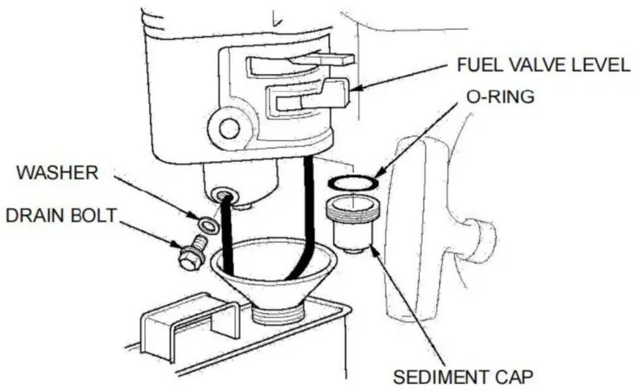
- After all the fuel has drained into the container, reinstall the drain I sediment cup. Tighten them securely.
STORAGE PROCEDURE
- Change the engine oil (see page 25).
2.Remove the spark plug(see page 27). - Pour a tablespoon(5-10 cc) of clean engine oil into the cylinder.
4.Pull the starter grip several times to distribute the oil in the cylinde
5.Reinstall the spark plug and attach the spark plug cap.
6.Pull the recoil starter grip slowly until resistance is felt. This will clo valves so moisture cannot enter the engine cylinder. Return the recoil starter grip gently.
STORAGE PRECAUTIONS
If your pump will be stored with gasoline in the fuel tank and carbun important to reduce the hazard of gasoline vapor ignition. Select a well-ventilated storage area away from any appliance that operates wit
flame, such as a furnace, water heater, or clothes dryer. Also, avoid area with a spark-producing electric motor or where power tools are operated.
If possible, avoid storage areas with high humidity because that promotes rust and corrosion.
Unless all fuel has been drained from the fuel tank, leave the fuel lever in the OFF position to reduce the possibility of fuel leakage.
Place the pump on a level surface. Tilting can cause fuel or oil leak
With the engine and exhaust system cool, cover the pump to keep c A hot engine and exhaust system can ignite or melt some materials. use sheet plastic as a dust cover. A nonporous cover will trap moist around the pump, promoting rust and corrosion.
REMOVAL FROM STORAGE
Check your pump as described in the CHECK BEFORE OPERATION chapter of this manual.
If the fuel was drained during storage preparation, fill the tank with f gasoline. If you keep a container of gasoline for refueling, be sure the contains only fresh gasoline. Gasoline oxidizes and deteriorates over time causing hard starting.
If the cylinder was coated with oil during storage preparation, the end might smoke briefly at startup. This is normal.
TRANSPORTING
If the pump has been running, allow the engine to cool for at least minutes before loading the pump on the transport vehicle. A hot engine exhaust system can burn you and can ignite some materials.
Keep the pump level when transporting to reduce the possibility of full leakage. Move the fuel valve lever to the OFF position.
TROUBLESHOOTING
ENGINE
| Engine Will Not Sta | Possible Cause | Correction |
| 1. Check control positions. | Fuel valve OFF. | Move fuel valve lever ON position. |
| Choke open. | Move choke lever to CLOSED position unless engine is warn | |
| Ignition switches OFF. | Turn ignition switch to ON. | |
| 2. Check fuel. | Out of fuel. | Refuel (p.24). |
| Bad fuel; pump stored without treating or draining gasoline, or refuel with bad gasolin | Drain fuel tank and carburetor (p.32). Refuel with fresh gasoline (p.24). | |
| 3. Remove and inspe spark plug. | Spark plug faulty, foule or improperly gapped. | Gap or replace spark plug (p.27). |
| Spark plug wet with fu (flooded engine). | Dry and reinstall spar plug. Start engine with throttle lever in FAST position. | |
| 4. Take engine to an authorized servicing dealer, or refer to s manual. | Fuel filter clogged, carburetor malfunction, ignition malfunction, valves stuck, etc. | Replace or repair fau components as necessary. |
| Engine Lacks Powe | Possible Cause | Correction |
| 1. Check air filter. | Air filter clogged. | Clean or replace filte (p.27). |
| 2. Check fuel. | Bad fuel; pump stored without treating or draini gasoline, or refuel with gasoline. | Drain fuel tank and carburetor (p.32). Refuel with fresh gasoline (p.24). |
| 3. Take engine to a authorized servicing dealer, or Refer to shop manual. | Fuel filter clogged, carburetor malfunction, ignition malfunction, valve stuck, etc. | Replace or repair faulty components as necessary. |
PUMP
| No Pump Output | Possible Cause | Correction |
| 1. Check pump chamber. | Pump not primed. | Prime the pump (p.1) |
| 2. Check suction hose | Hose collapsed, cut punctured. | Replace suction hose (p.14). |
| Strainer not complete underwater. | Sink the strainer and the end of a suction hose completely underwater. | |
| Air leak at connector | Replace sealing washer if missing or damaged. Tighten hos connector and clamp (p.14,16). | |
| Strainer clogged. | Clean debris from strainer. | |
| 3. Measure suction and discharge head. | Excessive head. | Relocate pump and/o hoses to reduce hea (p.13,14). |
| 4. Check engine. | Engine lacks power. | See page 23. |
SPECIFICATIONS
| Model | SCWP50 | SCWP80-II |
| Suction Port Diameter | 50 | 80 |
| Discharge Port Diameter | 50 | 80 |
| Maximum Flow | 32m³/h | 60m³/h |
| Total Head Lift | 45m | 43m |
| Suction (m) | 7 | 7 |
| Engine Mode | SV210 | SV210 |
| Displacement (cc) | 209 | 209 |
| Rated Speed (rpm) | 3600 | 3600 |
Tuneup
| Spark plug gap | 0.70- 0.80 mm | See page 28. |
| Idle speed | 1800±50rpm | |
| Valve clearance (cold) | Exhaust: 0.20±0.02 mm Intake: 0.15±0.02 mm | |
| Other specifications | No other adjustments are needed. | |
TECHNICAL & CONSUMER INFORMATION
Carburetor Modification for High Altitude Operation
At high altitudes, the standard carburetor air-fuel mixture will be too rich. The performance will decrease, and fuel consumption will increase. A rich mixture will also foul the spark plug and cause a hard start. Op at an altitude that differs from that at which this engine was certified extended periods of time may increase emissions.
High-altitude performance can be improved by specific modifications to carburetor. If you always operate your pump at altitudes above 5,000 (1,500 meters), have your servicing dealer perform this carburetor modification. This engine, when operated at a high altitude with the carburetor modifications for high altitude use, will meet each emission standard throughout its useful life.
Even with carburetor modification, engine horsepower will decrease by about 3.5% for every 1,000 feet (300 meters) increase in altitude. The effect of altitude on horsepower will be greater than this if no carbur modification is made.
NOTICE
When the carburetor has been modified for high-altitude operation, the air-fuel mixture will be too lean for low-altitude use. Operation altitudes below 5,000 feet (1,500 meters) with a modified carburet may cause the engine to overheat and result in serious engine damage. For use at low altitudes, have your servicing dealer retuthe carburetor to its original factory specifications.
Oxygenated Fuels
Some conventional types of gasoline are blended with alcohol or an oil compound. These types of gasoline are collectively referred to as oxygenated fuels. To meet clean air standards, some areas of the United States and Canada use oxygenated fuels to help reduce emissions.
If you use an oxygenated fuel, be sure it is unleaded and meets the minimum octane rating requirement.
Before using an oxygenated fuel, try to confirm the fuel's contents. Some states/provinces require this information to be posted on the pump.
The following are the EPA-approved percentages of oxygenates:
ETHANOL---(ethyl or grain alcohol) 10% by volume.
You may use gasoline containing up to 10% ethanol by volume. Gas containing ethanol may be marketed under the name "Gasohol".
MTBE---(methyl tertiary butyl ether) 15% by volume. You may use gasoline containing up to 15% MTBE by volume.
METHANOL---(methyl or wood alcohol) 5% by volume. You may use gasoline containing up to 5% methanol by volume as as it also contains cosolvents and corrosion inhibitors to protect the system. Gasoline containing more than 5% methanol by volume may cause starting and/or performance problems. It may also damage the metal, rubber, and plastic parts of your fuel system.
If you notice any undesirable operating symptoms, try another service station, or switch to another brand of gasoline.
Fuel system damage or performance problems resulting from the use of oxygenated fuel containing more than the percentages of oxygenates mentioned above are not covered under warranty.
Emission Control System Information
Source of Emissions
The combustion process produces carbon monoxide, oxides of nitrogen and hydrocarbons. Control of hydrocarbons and oxides of nitrogen is 'important because, under certain conditions, they react to form photochemical smog when subjected to sunlight. Carbon monoxide does not react in the same way, but it is toxic.
This utilizes lean carburetor settings and other systems to reduce the emissions of carbon monoxide, oxides of nitrogen, and hydrocarbons.
Tampering and Altering
Tampering with or altering the emission control system may increase emissions beyond the legal limit. Among those acts that constitute tampering are:
-Removal or alteration of any part of the intake, fuel, or exhaust syst
- Altering or defeating the governor linkage or speed-adjusting mechanism to cause the engine to operate outside its design parameters.
Problems That May Affect Emissions
If you are aware of any of the following symptoms, have your engine inspected and repaired by your servicing dealer.
- Hard starting or stalling after starting.
·Rough idle.
-Misfiring or backfiring under load.
Afterburning (backfiring).
- Black exhaust smoke or high fuel consumption.
Replacement Parts
The emission control systems on your engine were designed, built, and certified to conform with EPA and California emission regulations. We recommend the use of genuine parts whenever you have maintenance
done. These original-design replacement parts are manufactured to the same standards as the original parts, so you can be confident of the performance. The use of replacement parts that are not of the original design and quality may impair the effectiveness of your emission cont system.
A manufacturer of an aftermarket part assumes the responsibility that part will not adversely affect emission performance. The manufacturer rebuilder of the part must certify that the use of the part will not refailure of the engine to comply with emission regulations.
Maintenance
Follow the maintenance schedule on page 23. Remember that this schedule is based on the assumption that your machine will be used designed purpose. Sustained high-load or high-temperature operation, or use in unusually wet or dusty conditions, will require more frequent s
Air Index
An Air Index Information hang tag/label is applied to engines certified emission durability time period in accordance with the requirements of California Air Resources Board.
The bar graph is intended to provide you, our customer, the ability to compare the emissions performance of available engines. The lower the Index, the less pollution.
The durability description is intended to provide you with information relating to the engine's emission durability period. The descriptive term indicates the useful-life period for the engine's emission control system. See your Emission Control Warranty for additional information.
| Descriptive Term Applicable to Emission Durability Period | |
| Moderate | 50 hours (0–65 cc) 125 hours (greater than 65 cc) |
| Intermediate | 125 hours (0–65 cc) 250 hours (greater than 65 cc) |
| Extended | 300 hours (0–65 cc) 500 hours (greater than 65 cc) |
The Air Index Information hang tag must remain on the pump until it sold. Remove the hang tag before operating the pump.
CONSUMER INFORMATION
Publications
These publications will give you additional information for maintaining a repairing your pump. You may order them from your pump dealer.
Parts Catalog
This manual provides complete, illustrated parts lists.
Customer Service Information
Servicing dealership personnel are trained professionals. They should be able to answer any questions you may have. If you encounter a pro that your dealer does not solve to your satisfaction, please discuss it the dealership's management. The Service Manager or General Manager can help. Almost all problems are solved in this way.
Address: Baoshanqu Shuangchenglu 803long 11hao 1602A-1609shi Shanghai
| EC | REP |
SHUNSHUN GmbH
Römeräcker 9 Z2021,76351
Linkenheim-Hochstetten, Germany
| UK | REP |
Pooledas Group Ltd Unit 5 Albert Edward House, The Pavilions Preston, United Kingdom
Made In China
VEVOR®
TOUGH TOOLS, HALF PRICE
Support and E-Warranty Certificate https://www.vevor.com/support
VEVOR
TOUGH TOOLS, HALF PRICE
RECOMMANDATIONS DE CARBURANT
Pooledas Group Ltd Unit 5 Albert Edward House, The Pavilions Preston, United Kingdom
Fabrique en Chine
VEVOR
TOUGH TOOLS, HALF PRICE
MTBE---(Methyl-tertiarbutylether) 15 Vol.-%
Pooledas Group Ltd Unit 5 Albert Edward House, The Pavilions Preston, United Kingdom
Pooledas Group Ltd Unit 5 Albert Edward House, The Pavilions Preston, United Kingdom
Made in China
VEVOR
TOUGH TOOLS, HALF PRICE
NoOLLOWING INSTRUCTIONS NoOLLOWING INSTRUCTIONS
Un filtered spectrum is the sum of a spectrum of the frequency domain and a spectrum of the time domain.
Pooledas Group Ltd Unit 5 Albert Edward House, The Pavilions Preston, United Kingdom
Hecho en china
VEVOR
TOUGH TOOLS, HALF PRICE
INSTALACJA WEZA SPUSTOWEGO
Pooledas Group Ltd Unit 5 Albert Edward House, The Pavilions Preston, United Kingdom
VEVOR
TOUGH TOOLS, HALF PRICE
HULP NODIG? NEEM CONTACT MET ONS OP!
INSTALLATIE AFVOERSLANG
OPSLAGVOORZORGSGMAATREGELEN
Pooledas Group Ltd Unit 5 Albert Edward House, The Pavilions Preston, United Kingdom
Gemaakt in China
VEVOR
TOUGH TOOLS, HALF PRICE
Ondersteuning en E-garantiecertificaat https://www.vevor.com/support
VEVOR
TOUGH TOOLS, HALF PRICE
Pooledas Group Ltd Unit 5 Albert Edward House, The Pavilions Preston, United Kingdom
Tillverkad i Kina
VEVOR
TOUGH TOOLS, HALF PRICE