
NMBP11-G1100-40-12 - Water pump Vevor - Free user manual and instructions
Find the device manual for free NMBP11-G1100-40-12 Vevor in PDF.
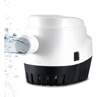


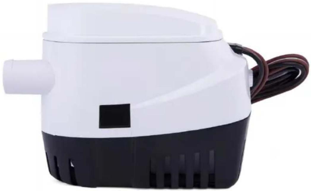
| Product Type | Submersible Automatic Bilge Pump |
| Brand | Vevor |
| Model | NMBP11-G1100-40-12 |
| Supply Voltage | 12 V DC |
| Power Consumption | 54 W |
| Maximum Flow Rate | 1100 GPH (approx 4164 L/h) |
| Maximum Head Height | 4 m |
| Outlet Hose Outer Diameter | 29 mm |
| Pump Type | Centrifugal Pump with Integrated Float Switch |
| Operating Mode | Automatic (water level detection) and manual (forced operation) |
| Electrical Protection | Appropriate fuse (amperage per specifications, not included) |
| Recommended Wire Gauge | 18 AWG wire |
| Housing Material | Corrosion-resistant plastic (ABS type) |
| Estimated Weight | Approximately 1.2 kg |
| Package Contents | Pump, strainer (filter), mounting base, user manual |
| Safety Instructions | Do not use for flammable liquids; keep electrical connections out of water; use appropriate fuse |
| Routine Maintenance | Regular cleaning of strainer and impeller; inspection of connections |
| Repairability | Cleanable; accessible impeller and float; replaceable wear parts |
| Operating Temperature | Do not use if frozen; withstands freezing temperatures but do not operate if caught in ice |
| Warranty | Technical support and electronic warranty certificate at www.vevor.com/support |
Frequently Asked Questions - NMBP11-G1100-40-12 Vevor
User questions about NMBP11-G1100-40-12 Vevor
0 question about this device. Answer the ones you know or ask your own.
Ask a new question about this device
Download the instructions for your Water pump in PDF format for free! Find your manual NMBP11-G1100-40-12 - Vevor and take your electronic device back in hand. On this page are published all the documents necessary for the use of your device. NMBP11-G1100-40-12 by Vevor.
USER MANUAL NMBP11-G1100-40-12 Vevor
Technical Support and E-Warranty Certificate
www.vevor.com/support
BOAT BILGE PUMP INSTRUCTIONS
MODEL: NMBP11-G1100-40-12 / NMBP11-G750-30-12
We continue to be committed to provide you tools with competitive price. "Save Half", "Half Price" or any other similar expressions used by us only represent estimate of savings you might benefit from buying certain tools with us compared to top brands and does not necessarily mean to cover all categories of tools offered. We kindly remind you to verify carefully when you are placing an order with us to ensure you are actually saving half in comparison with the top major brands.
MODEL: NMBP11-G1100-40-12 / NMBP11-G750-30-12
NEED HELP? CONTACT US!
Have product questions? Need technical support? Please feel free to contact us:
Technical Support and E-Warranty Certificate www.vevor.com/support
This is the original instruction. Please read all manual instructions carefully before operating. VEVOR reserves a clear interpretation of the user manual. The appearance of the product shall be subject to the product you received. Please forgive us that we won't inform you of any technology or software updates on our product.
 | Warning-To reduce the risk of injury, user must read instructions manual carefully. |
 | This product is subject to the provision of European D 2012/19/EC. The symbol showing a wheelie bin crossed through indicates that the product requires separate refi collection in the European Union. This applies to the p and all accessories marked with this symbol. Products as such may not be discarded with normal domestic v but must be taken to a collection point for recycling e and electronic devices |
PROPERTIES OF PRODUCTS
| Model | Input | Max power | Max flow | Max lift | Outer diameter of outlet pipe |
| NMBP11-G1100-40-12 | DC12V | 54W | 1100GPH | 4m | Φ29mm |
| NMBP11-G750-30-12 | DC12V | 43W | 750GPH | 3m | Φ19mm |
WARNING
CAUTION:
Read all instructions carefully before installing and using this product. This pump is sealed and, therefore, submersible. However, the electric wire connections must not be submerged. For extra protection, coat the butt joints and adjacent wire ends liberally with liquid electrical tape.
SECURITY:
The automatic bilge pump can only be used for pumping water. It cannot be used for other liquids. During installation, connect the pump's black wire to the negative (-) terminal and the brown or brown-white wire to the positive (+) terminal.
Use the appropriate fuse.
Wire connections must be sealed with marine sealant.
All wires and connections must be positioned above the bilge water level. Unless necessary, do not arbitrarily remove the insulator. Use marine sealant on all wires. Do not run dry.
WARNING:
- To prevent injury, always disconnect the power source when installing or servicing any electrical product. Do not use the pump to remove gasoline, oil, or other flammable liquids. Always use the fuse amperage rating specified for your pump model. Failure to do so could result in serious personal injury or fire.
OPTIONAL MATERIALS
- 1/2-inch-thick marine plywood block (slightly larger than pump base). Waterproof adhesive (epoxy, silicone adhesive, or fiberglass resin) to mount block. 18-gauge wire (brown, brown-white, and black).
PUMP MOUNTING INSTRUCTIONS
WARNING: Remove the pump mounting base (See Figure 3).
Remove the foam block that supports the float during shipping.
Failure to do this prevents the pump from starting when water is present.
Step 1: Press the hasps on both sides of the automatic bilge pump, and the filter away from the bottom of the pump.
NOTE: Before connecting or operating the pump, install the filter correctly. It is strictly prohibited to disconnect
the filter when the pump is running. The pump must be installed above water level.
Step 2: Ensure the best place when installing the pump. If you only have one pump, it is usually installed in the deepest place of the water line when the boat stops. You must install complete tubes for draining water.
Drain all sweepers by horizontal installation of water pipes, or placing pump in a higher position.
Step 3: Install the strainer.
A: When fixing the strainer on wood block, use Φ 4.0 mm stainless steel self-tapping screws.
B: If you fix the strainer to a metal or glass fiber, firstly install a pin wood on it, then fix the strainer to the piece of wood, then install the in the filter, and ensure that the two hasps are fastened.
Step 4: Connect a 3/4" ID pipe to the outlet nozzle, and clamp their stainless steel clamp. Recommend using the standard tubes, because they will not tie off by suddenly bending. If using a pipe with smaller diameter will not damage the pump, but will reduce the pump's flow.
Step 5: Wire. In order to prevent ruin or corrosion of the wire, it is in to fasten the ends of the wire and the terminals by insulators or place at the highest horizontal position as possible. When installing the pump, 18 wire is suggested. If too small wire is used, it will cause overhead inside, reducing the pressure and affecting the performance of the pump.
NOTE:
- Make sure the hull thickness is at least 1/2" thick. If not, place a 1/2" marine plywood (slightly larger than the pump base) in the lowest of the bilge. Be sure that the pump cover can be removed for clear this position. Glue the plywood to the hull with a waterproof adhesive (epoxy, silicone adhesive, or fiberglass resin). See figure 1.
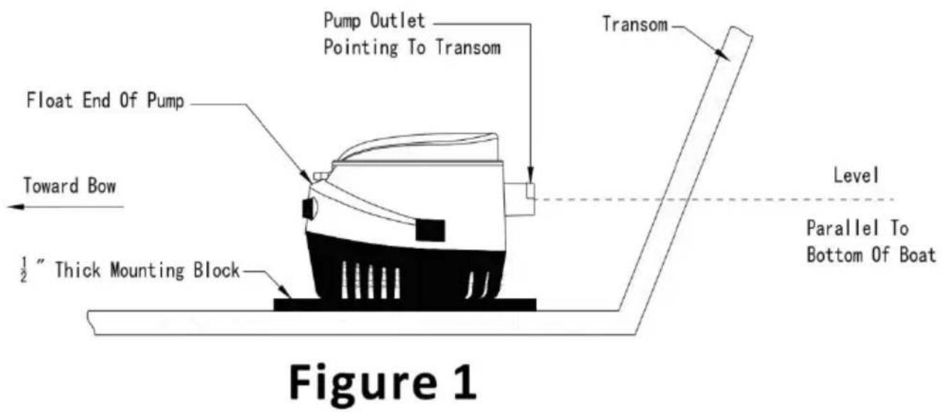
- Position the pump in the lowest part of the bilge on a flat, level (on the plywood block if it has been
installed) with the outlet pointing toward the transom.
Be sure outlet nozzle is level. If pointed upward or downward, an air may form in the pump. (See Figure 1)
- The float end of the pump must be level with or above the pump (See figure 1). This prevents the pump from running out of water while float is still high enough to activate the pump.
- Mark location of the three (3) mounting holes with a pencil or scrib
WARNING: When drilling holes do not drill through the hull!
- Carefully drill two 1/8" diameter pilot holes in marked area and drive a screw in each hole.
- Slide hose clamps (one to clamp hose to the pump, the other to thru-hull connector) over end of the hose. Force hose over the discharge nozzle of the pump. Install clamp.
- Route hose on an upward incline to the thru-hull connector. Avoid kinks in hose that can trap water and airlock the pump. Avoid putting excessive strain on hose, which can damage the pump outlet.
- Force the hose over the thru-hull fitting and clamp into place.
OPERATION:
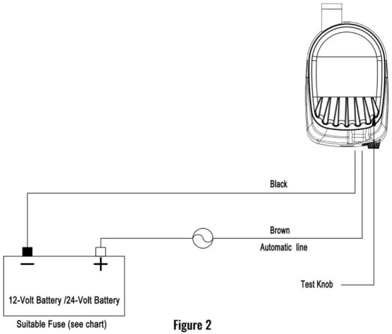
When the brown white wire of the auto bilge pump is connected to battery's positive (+) terminal, the black wire is connected to the battery negative (-) terminal, the pump has automatic function.
When the brown white wire of the auto bilge pump is connected to battery's positive (+) terminal, the black wire is connected to the battery negative (-) terminal, the pump has automatic function.
- When the water level rises above the bottom flat surface of the strainer - 50 mm, the float switch's contact point is connected then the pump works. 2. When the water level drops to 20-30 mm above the bottom surface of the strainer, the float switch's contact point is disconnected, float switch stops working, and then the pump ceases to work.
When the brown wire of the auto bilge pump is connected to the battery positive (+) terminal, the black wire is connected to the battery's negative terminal, this pump is same as the ordinary bilge pump and has no automatic function.
WARNING INSTRUCTIONS
WARNING: Be certain that power source is 12-volt D.C. / 24-volt D.C. voltage will damage the pump.
- Using the full length of wire provided (and additional wire if necessary), connect wires to the pump as shown in the diagram. (See Figure 2.)
- Route wires out of the way and secure them to the bulkhead to avoid pulling.
- Using butt connectors sized for 18-gauge wire, splice fuse holder into positive lead (brown) between the battery and switch.
Position fuse holder in a location that is easily accessible for changing fuses.
IMPORTANT: Use fuses of the proper amperage (See Specification Chart at top of sheet.)
Warning: FAILURE TO PROPERLY FUSE AND MAKE THE APPROPRIATE WATERPROOF CONNECTIONS WILL VOID THE PRODUCT WARRANTY.
- Install a Three-way switch that allows for automatic or manual switching models. 5. Turn the pump on and twist the Test Knob clockwise to check operation. Feed water into the pump. If output appears to be too low, check the wire connections. Reversed connections result in opposite impeller rotation that drastically reduces capacity and can cause premature pump failure.
CARE AND MAINTENANCE
Occasionally check your pump to be certain debris is not jamming the impeller and/or float within the housing. Use the test knob by rotating clockwise direction. Careful attention will guarantee outstanding pump performance.
- To clean the water chamber, remove pump housing from the mount base by pressing in tabs on sides. Lift the pump housing away. (Figure 3)
- To clean the impeller, remove the impeller guard screw and lift the impeller guard.
- Remove all debris that has accumulated in pump chamber and around the impeller. Ensure that all debris is removed from strainer slots around the pump base.
- Inspect the impeller to ensure that it is firmly attached to shaft and not cracked or broken.
- Replace the impeller guard, screw, and pump housing on the base. Be certain that all tabs are fully engaged.
- Periodically check the electrical connections to ensure they are water-resistant and mounted high and dry. Do not use household cleaners on the pump because many of them may damage the pump materials.
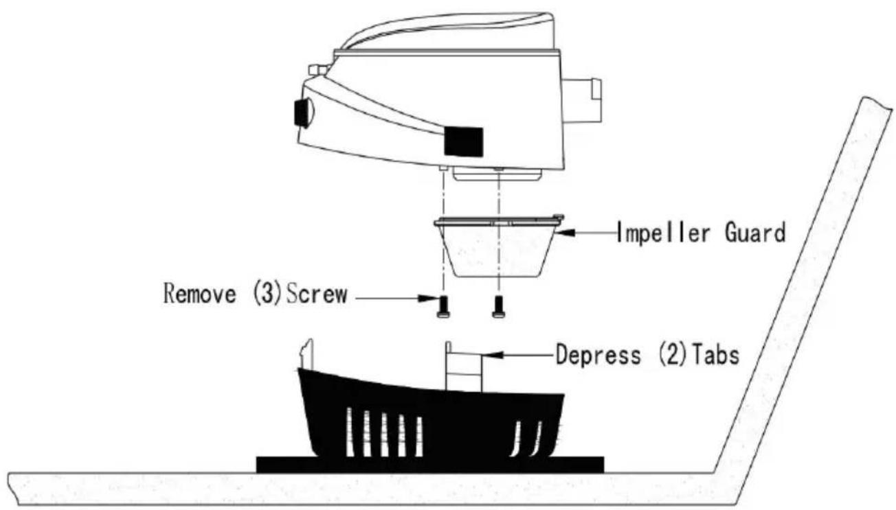
Figure 3
STORAGE
The pump itself is not affected by freezing temperatures. However, if the pump is embedded in ice or surrounded by ice, it cannot be operated. Never turn the pump on if it is embedded in or surrounded by ice.
| Symptom | possible cause | cure |
| Reduced Flow | Plugged strainer | Clean outside of strainer and clean debris from around impeller. |
| Discharge line plugged | Clean out hose by back flushing | |
| Low battery voltage | Check battery condition and charge if necessary. | |
| Kinked discharge hose | If hose is kinked because of sharp bend,convert to hose which will not kink bends. | |
| No water pumped | Wire connections | Make sure wire Connections are not corroded.Visual check is not enough -a s pull on each wire will tell if the wires are still joined. Check to be sure joins are hanging down into the water. |
| Fuse melted | Check fuse to see that it is the correct fuse still blows,check impeller through inlet opening to be sure it is no jammed or stuck with debris. | |
| Float switch failure | Lift end of float switch up-if pump runs, is OK.If pump does not run, turn Manual SWITCH TO on position-if pu runs automatic switch has failed. | |
| Pump won't shut off | Something under float | Clean under the float to make sure debris not holding the float up |
| Stuck float | Check to see that the float is loose and gummy bilge oil. If float action appears sluggish and/or the float does not move intermittent or sporadic operation of the p may occur.This condition is usually the result of oil and/or Dirt accumulating in a around the movable parts of the switch.To correct try soaking the entire switch In Marine cleaner for ten minutes, agitati several times and checking for smooth air free operation of the float. Repeat if necessary | |
| Switch mounted too Low IMPORTANT | If the pump is sucking air and the autorswitch has not reached the OFF position, the switch may be mounted too low for and should be pump reinstalled at least higher than the pump base. | |
| Wires over-heated. Melted insulation | Combination of jammed impeller and wrong size fuse. | Be sure impeller is clean of debris and to rotate Reduce fuse to proper size Replace damaged wiring and/or switch. |
| Repeated melted fuse | Fuse size or jammed impeller | Be sure fuse has amp rating Check imp to see that it is not bound up by fish I |
Manufacturer: Shanghai Muxin Muye Youxiangongsi
Address: Shuangchenglu 803nong11hao1602A-1609shi, Baoshanqu, Shanghai 200000 CN.
EC REP: E-CrossStu GmbH.
Mainzer Landstr. 69, 60329 Frankfurt am Main.
UK REP: YH CONSULTING LIMITED.
C/O YH Consulting Limited Office 147, Centurion House, London
Road, Staines-upon-Thames, Surrey, TW18 4AX
Imported to AUS: SIHAO PTY LTD.
1 ROKEVA STREET, EASTWOOD NSW 2122, Australia
Imported to USA: Sanven Technology Ltd.
Suite 250, 9166 Anaheim Place, Rancho Cucamonga, CA 91730
VEVOR®
TOUGH TOOLS, HALF PRICE
Technical Support and E-Warranty Certificate
www.vevor.com/support
VEVOR®
TOUGH TOOLS, HALF PRICE
NEED HELP? CONTACT US!
PRODUCT PROPERTIES
Figure 1
IMPROPER WATERPROOF CONNECTIONS VOID THE
PRODUCT WARRANTY.
Figure 3
STORAGE
C/O YH Consulting Limited Bureau 147, Centurion House, London Road, Staines-upon-Thames, Surrey, TW18 4AX
Imported in AUS: SIHAO PTY LTD.
1 ROKEVA STREET EASTWOOD NSW 2122 Australia
Suite 250, 9166 Anaheim Place, Rancho Cucamonga, CA 91730
VEVOR®
TOUGH TOOLS, HALF PRICE
www.vevor.com/support
VEVOR®
TOUGH TOOLS, HALF PRICE
www.vevor.com/support
Figure 1
Figure 3
STORAGE
C/O YH Consulting Limited Office 147, Centurion House, London
Straße, Staines-upon-Thames, Surrey, TW18 4AX
Suite 250, 9166 Anaheim Place, Rancho Cucamonga, CA 91730
VEVOR®
TOUGH TOOLS, HALF PRICE
www.vevor.com/support
VEVOR®
TOUGH TOOLS, HALF PRICE
electronics www.vevor.com/support
BOAT BILGE PUMP
INSTRUCTIONS
MODEL: NMBP11-G1100-40-12 / NMBP11-G750-30-12
PRODUCT PROPERTIES
Figure 1
Figure 3
STORAGE
C/O YH Consulting Limited Office 147, Centurion House, London Road, Staines-upon-Thames, Surrey, TW18 4AX
Imported into AUS: SIHAO PTY LTD.
1 ROKEVA STREET EASTWOOD NSW 2122 Australia
Suite 250, 9166 Anaheim Place, Rancho Cucamonga, CA 91730
VEVOR®
TOUGH TOOLS, HALF PRICE
electronics www.vevor.com/support
VEVOR®
TOUGH TOOLS, HALF PRICE
Figure 1
Figure 3
STORAGE
Road, Staines-upon-Thames, Surrey, TW18 4AX
Imported into AUS: SIHAO PTY LTD.
1 ROKEVA STREET EASTWOOD NSW 2122 Australia
Suite 250, 9166 Anaheim Place, Rancho Cucamonga, CA 91730
VEVOR®
TOUGH TOOLS, HALF PRICE
www.vevor.com/support
VEVOR®
TOUGH TOOLS, HALF PRICE
NEED HELP? CONTACT US!
Figure 1
Figure 3
STORAGE
C/O YH Consulting Limited Office 147, Centurion House, London
Road, Staines-upon-Thames, Surrey, TW18 4AX
Imported to AUS: SIHAO PTY LTD.
1 ROKEVA STREETEASTWOOD NSW 2122 Australia
Imported to USA: Sanven Technology Ltd.
Apartment 250, 9166 Anaheim Place, Rancho Cucamonga, CA 91730
VEVOR®
TOUGH TOOLS, HALF PRICE
www.vevor.com/support
VEVOR®
TOUGH TOOLS, HALF PRICE
Technical support and e-warranty certificate www.vevor.com/support
BOAT BILGE PUMP INSTRUCTIONS
MODEL: NMBP11-G1100-40-12 / NMBP11-G750-30-12
NEED HELP? CONTACT US!
Figure 1
WARNING INSTRUCTIONS
Figure 3
STORAGE
C/O YH Consulting Limited Office 147, Centurion House, London
Weg, Staines-upon-Thames, Surrey, TW18 4AX
Suite 250, 9166 Anaheim Place, Rancho Cucamonga, CA 91730
VEVOR®
TOUGH TOOLS, HALF PRICE
www.vevor.com/support
VEVOR®
TOUGH TOOLS, HALF PRICE
www.vevor.com/support
BOAT PUMP
INSTRUCTIONS
MODEL: NMBP11-G1100-40-12 / NMBP11-G750-30-12
NEED HELP? CONTACT US!
Figure 1
Figure 3
STORAGE
UK REP: YH CONSULTING LIMITED.
C/O YH Consulting Limited Office 147, Centurion House, London Road, Staines-upon-Thames, Surrey, TW18 4AX
Imported to AUS: SIHAO PTY LTD.
1 ROKEVA STREET EASTWOOD NSW 2122 Australia
Imported to USA: Sanven Technology Ltd.
Suite 250, 9166 Anaheim Place, Rancho Cucamonga, CA 91730
VEVOR®
TOUGH TOOLS, HALF PRICE
www.vevor.com/support
- BOAT BILGE PUMP INSTRUCTIONS
- NEED HELP? CONTACT US
- WARNING
- CAUTION
- SECURITY
- OPTIONAL MATERIALS
- PUMP MOUNTING INSTRUCTIONS
- STEP 3: INSTALL THE STRAINER
- NOTE
- OPERATION
- WARNING INSTRUCTIONS
- WARNING: FAILURE TO PROPERLY FUSE AND MAKE THE APPROPRIATE WATERPROOF CONNECTIONS WILL VOID THE PRODUCT WARRANTY
- CARE AND MAINTENANCE
- STORAGE
- VEVOR®
- TOUGH TOOLS, HALF PRICE
- BOAT BILGE PUMP
- INSTRUCTIONS
- MODEL: NMBP11-G1100-40-12 / NMBP11-G
- BOAT PUMP
Brand : Vevor
Model : NMBP11-G1100-40-12
Category : Water pump