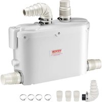
HSP1100II - Water pump Vevor - Free user manual and instructions
Find the device manual for free HSP1100II Vevor in PDF.

| Product Type | Water pump for spa, pool and jacuzzi |
| Brand | Vevor |
| Model | HSP1100II |
| Power supply | 220-240 V ~ 50 Hz, single phase |
| Maximum power | 1100 W |
| Motor type | Two speeds (1450 rpm low, 2900 rpm high) |
| Maximum flow rate | 35,000 L/h |
| Nominal flow rate | 14,000 L/h |
| Maximum head | 13 m |
| Minimum head | 2.8 m |
| Inlet/outlet connection | 2 x 2 inches (50.8 mm) |
| Self-priming | No |
| Thermal protection | Integrated, automatic reset at high speed |
| Maximum water temperature | 50 °C |
| Insulation class | Class I |
| Required safety device | GFCI (RCD) with trip current ≤ 30 mA |
| Intended use | Permanently installed pools, spas, jacuzzis, hydromassage |
| Installation | Horizontal, screw-mounted, short pipes |
| Maintenance | Disassemble, clean, store dry if inactive for long periods |
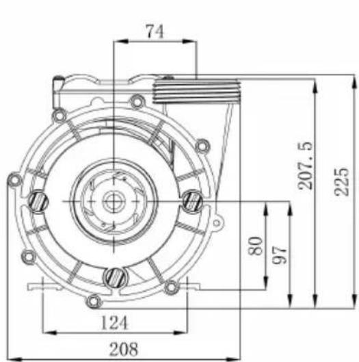
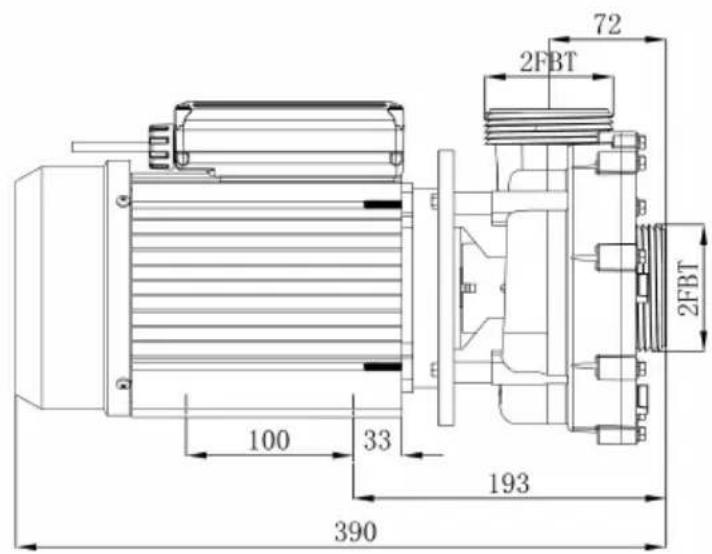
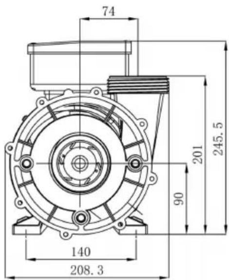
| Approximate dimensions (L x W x H) | 207.5 x 124 x 225 mm (from diagram) |
| Warranty and support | Electronic warranty via www.vevor.com/support |
Frequently Asked Questions - HSP1100II Vevor
User questions about HSP1100II Vevor
0 question about this device. Answer the ones you know or ask your own.
Ask a new question about this device
Download the instructions for your Water pump in PDF format for free! Find your manual HSP1100II - Vevor and take your electronic device back in hand. On this page are published all the documents necessary for the use of your device. HSP1100II by Vevor.
USER MANUAL HSP1100II Vevor
Technical Support and E-Warranty Certificate
www.vevor.com/support
SPA PUMPS
INSTRUCTION MANUAL
MODEL: HSP1100II,HDP1800II,HDP2200II
We continue to be committed to provide you tools with competitive price.
"Save Half", "Half Price" or any other similar expressions used by us only represents an estimate of savings you might benefit from buying certain tools with us compared to the top brands and does not necessarily mean to cover all categories of tools offered by us.
are kindly reminded to verify carefully when you are placing an order with us if you are actually saving half in comparison with the top major brands.
MODEL: HSP1100 II, HDP1800 II, HDP2200 II
natural_image
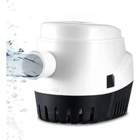
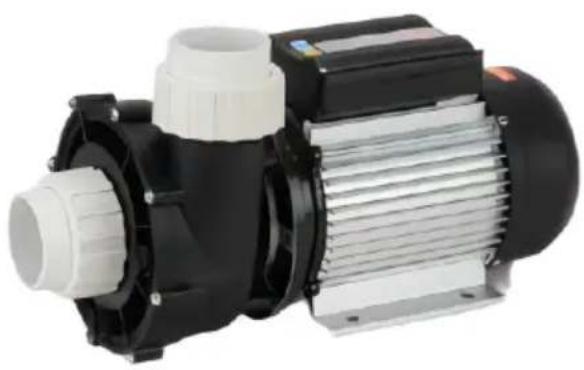
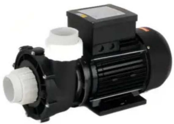
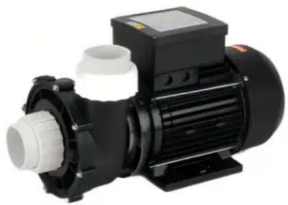
Exterior view of a black and white electric motor with cooling fins and housing (no text or symbols visible)HSP1100 II
natural_image
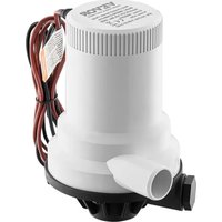
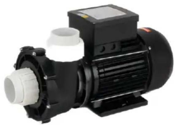
Black and white industrial motor with control panel and side ports (no visible text or symbols)HDP1800II, HDP2200II
NEED HELP? CONTACT US!
Have product questions? Need technical support? Please feel free to contact us:
Technical Support and E-Warranty Certificate www.vevor.com/support
This is the original instruction, please read all manual instructions carefully before operating. VEVOR reserves a clear interpretation of o user manual. The appearance of the product shall be subject to the product you received. Please forgive us that we won't inform you ag there are any technology or software updates on our product.
IMPORTANT SAFETY INSTRUCTIONS
When installing and using this electrical equipment, basic safety precautions should always be followed, including the following:
1) READ AND FOLLOW ALL INSTRUCTIONS
2) WARNING - To reduce the risk of injury, do not permit children to this product unless they are closely supervised at all times.
3) WARNING -Risk of Electric Shock. Connect only to a branch circuit protected by a ground-fault circuit-interrupter (GFCI). Contact a qualified electrician if you can not verify that the circuit is protected by a GFCI
4) The unit must be connected only to a supply circuit that is protected by a ground-fault circuit-interrupter (GFCI). Such a GFCI should be provided by the installer and should be tested on a routine basis. To the GFCI, push the test button. The GFCI should interrupt power. Push reset button. Power should be restored. If the GFCI fails to operate in manner, the GFCI is defective. If the GFCI interrupts power to the p without the test button being pushed, a ground current is flowing, ind the possibility of an electric shock.
Do not use this pump. Disconnect the pump and have the problem corrected by a qualified service representative before using it.
5) WARNING - To reduce the risk of electric shock, replace damaged immediately.
6) Do not install within an outer enclosure or beneath the skirt of a or spa.
7) CAUTION- This pump is for use with permanently-installed pools and may also be used with hot tubs and spas if so marked. Do not use storable pools. A permanently-installed pool is constructed in or on the ground or in a building such that it cannot be readily disassembled for storage. A storable pool is constructed so that it is capable of being readily disassembled for storage and reassembled to its original integri
8) SAVE THESE INSTRUCTIONS.
These instructions are for correct installation, and optimum performance the Bath pumps.
Statement
These instructions are for correct installation, and optimum performance of Bath pumps, so they should be read carefully. These are single-stage centrifugal pumps designed to operate with compact hydromassage equipment, They are equipped with a total-emptying system to prevent the discharge of residual liquid in each stopping.
These units are designed to operate with clean water at a maximum water temperature of 50^ C.
Built of top quality materials, they are subjected to strict hydraulic and electrical controls and are carefully verified. Correct installation is ensured by following these instructions and those of the wiring diagram; otherwise, overloads may be produced in the motor. We decline responsibility for an damage caused by not following these instructions.
PRODUCT PARAMETER
| Model HSP1100II HDP1800II | HDP2200II | |
| Speed type Two-speed Two-speeTwo-speed d | ||
| Input AC220-240V 50 Hz | ||
| Max powe 1100W | 1600W | 1900W |
| Q max 35000L/H | 39000L/H 43000L/H | |
| Q min 14000L/H | 19000L/H | 21500L/H |
| H max 13m | 15m | 18 m |
| H min 2.8m | 3.9 m | 4.4 m |
| Self-absorption function No | No | No |
| Inlet/outlet caliber 2.0 x 2.0 inches | ||
1. Installation
The pumps should be installed horizontally, securing them with screws through the holes in the supports to prevent undesirable noise and vibration.
The suction, pipe of the pump should be as short as possible.
The rating Label must be visible after installation. Parts containing live pa except parts supplied with safety extra low voltage<12V, must be inaccess to a person in the bath.
Class I appliances must be permanently connected to fixed wiring. Part including electrical components except remote control devices must be local or fixed so that they cannot into bath.
2.Pipe Assembly
The suction and discharge pipes should have a diameter equal to or gre than that of the intake tapping of the pump.
Avoid traps as, in addition to affecting efficiency, they impede total overall emptying.
The suction and discharge pipes should not rest on the pump in any ca Seal all the connectors and unions well. Avoid any dripping on the motor which would unfailingly damage it.
3. Electrical connection
The electrical install action should have a multiple separation system with contacts opening at least 3mm.
For continued protection against possible electric shock this unit is to be mounted to the base in accordance with the installation instructions.
The protection of the system should be based on a residual current device (RCD) with a rated tripping current not exceeding 30mA. The supply cable should comply with EMC standards (2). Single-phase motors have built-in thermal protector. When the pump run under abnormal condition and causes the thermal protector to work, please cut off the pump power if it is at speed (1450r/min) and plug in 1 minute later. If the pump is at a high (2900r/min), it will start work again when the thermal protector reset automatically as the motor temperature drops to a certain degree.
The diagrams in Fig.(1) correct electrical connection. The electric connection must be carried out by qualified staff following strictly the "60335-1, IEC 60335-2-41" standard.
Be sure that the grounding connection is correctly made.
Be sure that the equipotential connection between the bath and the pump correctly made.
Wires serving as equipotential bonding conductors shall have a cross-sectional area between 2.5 and 6mm^2 and shall be equipped with the terminal suitable receptacle.
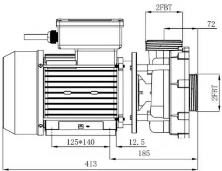
Installation structure
HSP1100II
HDP1800II/HDP2200II
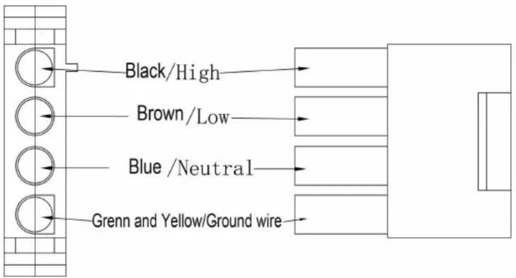
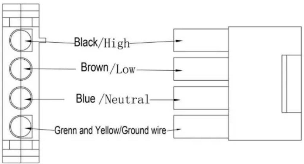
Installation circuit diagram
As the colors of the wires in the mains lead of this appliance may correspond with the colored markings identifying the terminals in your connection unit proceed as follows.
The wire, which is colored green-and-yellow,
must be connected to the terminal in the
connection unit which is marked with the letter E or by the earth sy green-and-yellow.
Brown wire and Blue wire connected with power supply is low speed.
Black wire and Blue wire connected with power supply is high sp
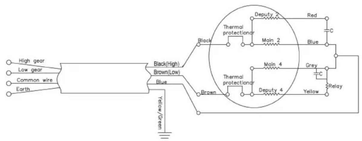
Schematic diagram of the AMP plug connection
1. Controls Prior to Initial Start-up
Verify that the pump shaft turns freely.
Check that the mains voltage and frequency are according to the nameplate. The hydromassage assembly should be equipped with a system to prevent the pump from starting up if a minimum water level is not present.
Check the rotating direction of the motor, which should concur with that indicated on the fan cover.
If the motor does not start up, try to locate the problem in the table of common faults and their possible solutions that is provided further on.
Start electrically the pump only when the suction and discharge pipes are connected to the corresponding inlets and outlets. Check that there is no obstacle in the pipes.
Apply voltage to the motor and suitably adjust the jets to obtain the des flow.
MAINTENANCE AND CLEAN
Our pumps for hydromassage facilities do not require any special maintenance or programming.
If the pump will be idle for a long period of time, it is recommended disassemble, clean and store it in a dry, well-ventilated place. If the supply cord is damaged, it must be replaced by the manufacturer or service agent or a similarly qualified person to a hazard.
Pump can be automotive empty water after correct installation.
When the pump needs to clean (1) filling with water up to level post of bathtub's nozzle, (2) operating 2-3minute,(3) exhausting water of bathtub after engine stop.
TROUBLE SHOOTING GUIDE
| SYMPTOM | POSSIBLE CAUSE | CHECK |
| PUMP DOESNO TURN | NO POWERTO PUMP | -incoming power to the pump?-Is circuit breaker on?-Is GFCI operating properly?-Is the air switch plugged in? |
| AIR SWITCHDISCONNECTED | -Is the air switch hose connected to the pump?-Is the air switch hose connected to the actuator button on the tub deck? | |
| PUMP NOTPUMPINGPROPERLY | BLOCKAGE ORLEAK | -Jets should be pointed away from the suction inlet so air is not forced into pump suction-Is the in-tub suction inlet blocked or covered?-Is there any debris in the pump housing?-Is there a leak in the piping or the pump? |
| LOW VOLTAGE | -Is the proper voltage applied to the pump?-Is there an extension cord being used? |
Correct Disposal
This product is subject to the provision of european Directive 2012/19/El. The symbol showing a wheelie bin crossed through indicates that the product requires separate refuse collection in the European Union. This applies to the product and all accessories marked with this symbol. Products marked as such may not be discarded with normal domestic waste, but must be taken to a collection point for recycling electrical and electronic devices.
VEVOR®
TOUGH TOOLS, HALF PRICE
Technical Support and E-Warranty Certificate
www.vevor.com/support
VEVOR®
TOUGH TOOLS, HALF PRICE
MANUEL D'INSTRUCTIONS
MODÈLE : HSP1100II, HDP1800II, HDP2200II
natural_image
Exterior view of a black and white electric motor with internal components (no visible text or symbols)HSP1100 II

natural_image
Exterior view of a black and white electric motor with no visible text or symbolsHDP1800I Je, HDP 2 2 0 0 II
BESOIN D'AIDE? CONTACTEZ-NOUS!
DÉCLARATION D'OPÉRATION
www.vevor.com/support
SPA-PUMPEN
BEDIENUNGSANLEITUNG
MODELL: HSP1100II,HDP1800II,HDP2200II
natural_image
Exterior view of a black and white electric motor with internal components (no visible text or symbols)HSP1100 II

natural_image
Black and white industrial motor with control panel and side ports (no visible text or symbols)HDP1800I I , HDP 2 2 0 0 II
BETRIEBSERKLÄRUNG
www.vevor.com/support
VEVOR®
TOUGH TOOLS, HALF PRICE
elettronica www.vevor.com/support
POMPE SPA
natural_image
Exterior view of a black and white electric motor with internal components (no visible text or symbols)Modello HSP1100 II
natural_image
Electric motor with black housing and white internal components (no visible text or symbols)Modello HDP1800I, HDP 2 2 0 0 II
natural_image
Exterior view of a black and white electric motor with internal components (no visible text or symbols)HSP1100 II

natural_image
Electric motor with black housing and white internal components (no visible text or symbols)HDP1800I Yo, HDP 2 2 0 0 II
natural_image
Exterior view of a black and white electric motor with internal components (no visible text or symbols)HSP1100 II

natural_image
Exterior view of a black and white electric motor with no visible text or symbolsHDP1800I ja , HDP2 2 0 0 II
POTRZEBUJESZ POMOCY? SKONTAKTUJ SIĘ Z NAMI!
DEKLARACJA OPERACYJNA
POMPA NIGDY NIE POWINNA PRACOWAĆ NA SUCHO.
2.Rozpoczę cie
natural_image
Exterior view of a black and white electric motor with internal components (no visible text or symbols)HSP1100 II

natural_image
Exterior view of a black and white electric motor with no visible text or symbolsHDP1800I Ik, HDP 2 2 0 0 II
HULP NODIG? NEEM CONTACT MET ONS OP!
Schematisch diagram van de AMP-stekkerverbinding
OPERATIEVERKLARING
www.vevor.com/support
SPA PUMPAR
BRUKSANVISNING
MODELL: HSP1100II, HDP1800II, HDP2200II
natural_image
Exterior view of a black and white electric motor with internal components (no visible text or symbols)HSP1100 II
natural_image
Black and white industrial motor with control panel and side ports (no visible text or symbols)HDP1800I I, HDP 2 2 0 0 II
BEHÖVER HJÄLP? KONTAKTA OSS!
DRIFTSDEKLARATION
www.vevor.com/support