OMS150S - Electric motor Vevor - Free user manual and instructions
Find the device manual for free OMS150S Vevor in PDF.

| Product Type | Electric Trolling Motor |
| Brand | Vevor |
| Model | OMS150S |
| Weight | Approximately 29.5 kg (65 lb) |
| Power Supply | 12 V DC Battery (12 V system) |
| Maximum Current | 50 A |
| Main Functions | Multifunction wireless remote, direction control, variable speed 0-10, automatic navigation modes |
| Operating Modes | Fixed heading, cruise, anchor, pilot (route following), go to point, route recording |
| Remote Control | LCD screen, directional handle, function buttons, battery indicator, GNSS signal level and remote |
| External Sensor | Optional, normal operation and error indicator, anti-tangle function |
| Protections | Automatic shutdown after 1 hour without input, overcurrent protection (alarm at 60 A, shutdown at 70 A), thermal protection (shutdown at 80 °C), propeller obstacle detection, low battery detection |
| Standards | European safety certification, compliant with FCC Part 15, WEEE directive 2012/19/EU |
| Included Accessories | Remote control, external sensor (optional), propeller, nuts, screws, hex key, brackets, gaskets, etc. (see parts list) |
| Spare Parts and Repairability | Detailed parts list in the manual, technical support via www.vevor.com/support. Warranty: electronic warranty certificate. |
| Maintenance | Regular cleaning, propeller inspection, cable inspection, recharge battery within 12 to 24 hours after use |
| Safety | Do not run out of water, keep away from propeller, use Vevor approved accessories, follow wiring instructions |
Frequently Asked Questions - OMS150S Vevor
User questions about OMS150S Vevor
0 question about this device. Answer the ones you know or ask your own.
Ask a new question about this device
Download the instructions for your Electric motor in PDF format for free! Find your manual OMS150S - Vevor and take your electronic device back in hand. On this page are published all the documents necessary for the use of your device. OMS150S by Vevor.
USER MANUAL OMS150S Vevor
Technical Support and E-Warranty Certificate www.vevor.com/support
Electric Trolling Motor
Model: OMS150S
We continue to be committed to provide you tools with competitive price. "Save Half", "Half Price" or any other similar expressions used by us only represents an estimate of savings you might benefit from buying certain tools with us compared to the major top brands and does not necessarily mean to co all categories of tools offered by us. You are kindly reminded to verify carefully when you are placing an order with us if you are actually Saving Half in comparison with the top major brands.
VEVOR®
TOUGH TOOLS, HALF PRICE
Electric Trolling Motor
Model: OMS150S
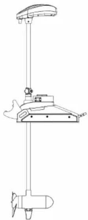
natural_image
Technical line drawing of a vertical electric motor or propeller device (no text or symbols)NEED HELP? CONTACT US!
Have product questions? Need technical support? Please feel free to contact us:
Technical Support and E-Warranty Certificate www.vevor.com/support
This is the original instruction, please read all manual instructions care before operating. VEVOR reserves a clear interpretation of our user manual. The appearance of the product shall be subject to the product received. Please forgive us that we won't inform you again if there are technology or software updates on our product.

Warning: To reduce the risk of injury, the user must read the instructions manual carefully.

Comply with the European security certification.
CORRECT DISPOSAL
This product is subject to the provision of european Directive 2012/19/EU.
The symbol showing a wheelie bin crossed through indicates that the product requires separate refuse collection in the European Union.
This applies to the product and all accessories marked with this symbol. Products marked as such may not be discarded with normal domestic wa but must be taken to a collection point for recycling electrical and electro devices.
FCC Information:
CAUTION: Changes or modifications not expressly approved by the party responsible for compliance could void the user's authority to operate the equipment!
This device complies with Part 15 of the FCC Rules. Operation is subject the following two conditions:
1) This product may cause harmful interference.
2) This product must accept any interference received, including interference that may cause undesired operation.
WARNING: Changes or modifications to this product not expressly approved by the party.
responsible for compliance could void the user's authority to operate the product.
Note: This product has been tested and found to comply with the limits Class B digital device pursuant to Part 15 of the FCC Rules, These
limits are designed to provide reasonable protection against harmful interference in a residential installation.
This product generates, uses and can radiate radio frequency energy, and not installed and used in accordance with the instructions, may cause harmful interference to radio communications. However, there is no guarantee that interference will not occur in a particular installation. If this product does cause harmful interference to radio or television reception, which can be determined by turning the product off and on, the user is encouraged to try to correct the interference by one or more of the following measures.
Reorient or relocate the receiving antenna.
Increase the distance between the product and receiver.
- Connect the product to an outlet on a circuit different from that to whi the receiver is connected.
- Consult the dealer or an experienced radio/TV technician for assistance.
SAFETYCONSIDERATIONS
Please thoroughly read the user manual. Follow all instructions and heed all safety and cautionary notices. Use of this motor is only permitted for persons that have read and understood these user instructions. Minors may use this motor only under adult supervision.
WARNING!
You are responsible for the safe and prudent operation of your vessel. We have designed your VEVOR product to be an accurate and reliable tool that will enhance boat operation and improve your ability to catch fish. This product does not relieve you from the responsibility for safe operation of your boat. You may avoid hazards to navigation and always maintain a permanent watch so you respond to situations as they develop. You must always be prepared to regulate manual control of your boat. Learn to operate your VEVOR product in an air free from hazards and obstacles.
WARNING!
Never run the motor out of the water, as this may result in injuries from the rotating propeller. The motor should be disconnected fro the power source wh
it is not in use or is off the water. When connecting the power-supply cable the motor to the battery, ensure that they are not kinked or subject to chafe route them in such a way that persons cannot trip over them. Before using motor make sure that the insulation of the power cables is not damaged. Disregarding these safety precautions may result in electric short of battery(s) and/or motor. Always disconnect motor from battery(s) before cleaning or checking the propeller. Avoid submerging the complete motor as water may enter the lower unit through control head and shaft. If the motor is used wh water is present in the lower unit considerable damage to the motor can occur. This damage will not be covered by warranty.
WARNING!
Take care that neither you nor other persons approach the turning propeller is closely, neither with body parts nor with object. The motor is powerful and may endanger or injure you or others. While the motor is running watch out for persons swimming and for floating objects. Persons who lack the ability to run the motor or whose reactions are impaired by alcohol, drugs, medication, or other substances are not permitted to use this motor. This motor is not suitable for use in strong currents. The constant noise pressure level of the motor does use is less than 70dB(A). The overall vibration level does not exceed 2,5 m/sec ^2 .
WARNING!
When stowing or deploying the motor, keep fingers clear of all hinge and piv points and all moving parts. in the event of unexpected operation, remove power leads from the battery
WARNING!
It is recommended to only use VEVOR approved accessories with your VEVC motor. Using non-approved accessories including to mount or control your motor may cause damage, unexpected motor operation and injury. Be sure to use the product and approved accessories, including remotes, safely and in the manner directed to avoid accidental or unexpected motor operation. Keep all factory installed parts in place including motor and accessory covers, enclosures and guards
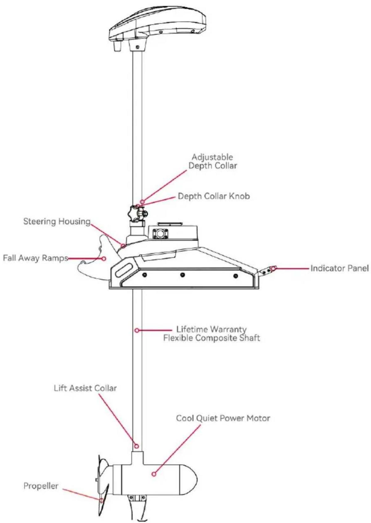
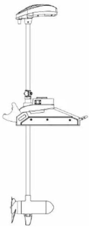
FEATURES
NOTICE: Specifications subject to change without notice. This diagram is for reference only and may differ from your actual motor.
INSTALLATION
Your new equipment arrives with all necessary components for direct installation onto the boat. This motor can be mounted directly onto th or coupled with a quick-release bracket to facilitate ease of mounting removal. For installation utilizing a quick-release bracket, please refer t the installation instructions supplied with the bracket. For compatible quick-release mounting brackets and to locate your nearest dealer, visi www.vevor.com. To install the motor directly onto the boat, please adl to the instructions outlined in this manual. Prior to beginning installatic please review the parts list, mounting considerations, and tools require installation. For additional product support, please visit
www.vevor.com/support.
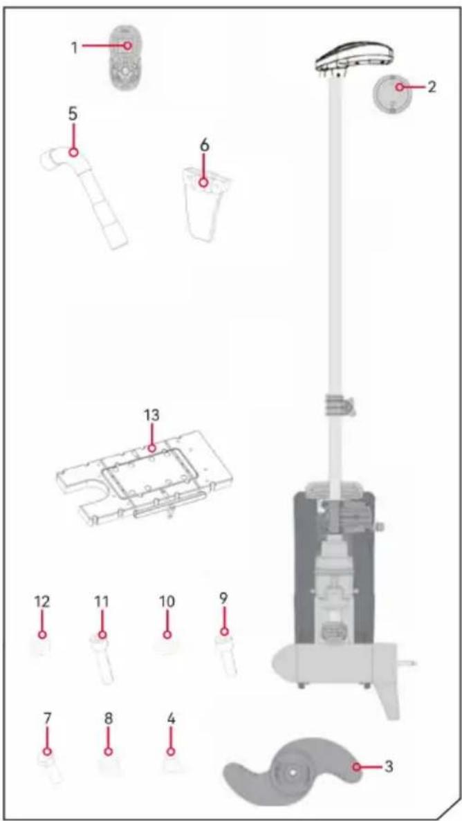
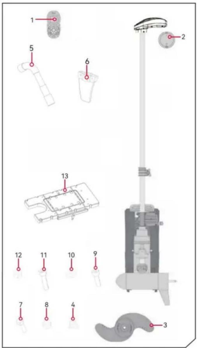
INSTALLATION PARTS LIST
| Item/ Assembly | Description | Qty. |
| 1 | Remote Control | 1 |
| 2 | External Sensor(Optional) | 1 |
| 3 | Propellor | 1 |
| 4 | M10 nut | 1 |
| 5 | M15 hexagonal spanner | 1 |
| 6 | Fins | 1 |
| 7 | M5*16 hexagon socket screws | 2 |
| 8 | M5 nut | 2 |
| 9 | M6*16 hexagon socket screws | 4 |
| 10 | gaskets | 1 |
| 11 | M6*25 hexagon socket screw | 12 |
| 12 | M6 nut | 4 |
| 13 | Plastic quick release Bracket | 1 |
Remote-control unit
Review the complete CoPilot section of this manual to become familia this feature. For more information on CoPilot or for additional product support. please visit www.vevor.com.
> Propeller ON/OFF Function
The button responsible for activating or deactivating the propeller is conveniently situated at the center of the remote control. To initiate the rotation of the propeller, simply press this button once; to halt the ro press it again. It is important to note that maintaining pressure on the button is not necessary for it to function.
> Steering Mechanism: Left & Right
The steering lever is positioned centrally on the remote control. When need arises to adjust the direction to the left or right, one simply ne displace the steering lever in the respective direction. These buttons t direct the motor to rotate in the corresponding direction, thereby enable precise control over the movement of the device. This operation reser the manipulation of a game controller and is highly convenient.
If either the right or left steering button is pressed continuously for a duration exceeding seven seconds, the steering mechanism will automatically cease operation until the button is pressed once again.
> Speed Adjustment: Accelerate & Decelerate
The buttons responsible for controlling the acceleration and deceleration functions are conveniently positioned right in the middle of the remote control unit. Whenever there is a need to either speed up or slow down device, one simply needs to manipulate the steering lever by flicking the desired direction, either forward or backward, to achieve the desired change in speed. With each flick of the lever, the speed can be incrementally adjusted, allowing for a gradual increase or decrease by unit at a time. The speed range itself is highly versatile and can be customized to span from a complete standstill at level 0, all the way maximum speed of 10. This means that at level 0, the propeller is a motionless, providing a full stop, while at level 10, the propeller operates its highest possible speed, offering a wide spectrum of control options the user.
In audio mode 2, an audible beep is emitted for each incremental ch
in speed, providing auditory feedback during adjustments. Attempts to the speed above 10 or below 0 will be met with no change in speed accompanying beep, serving as a safeguard against invalid settings. For more comprehensive understanding of the Audio Mode, please refer to relevant section in the manual.
Should the receiver fail to detect any input from the foot pedal or re a continuous period of one hour, the remote speed setting will default zero. This safety feature is designed to prevent any accidental activation the propeller, should the Propeller ON/OFF button on the remote be accidentally engaged.
MOUNTING CONSIDERATIONS
It is advisable to mount the motor as near to the centerline of the vessel a. Ensure that the area beneath the mounting point is unobstructed to facilitate drilling of holes and the installation of nuts and washers. Furthermore, ensure the motor rest extends sufficiently beyond the boat's edge. The motor must re encounter any impediments during the process of being lowered into the water raised back into the boat, both when deployed and when stowed. The install: a quick release or adapter bracket should be considered in conjunction with motor installation.
TOOLS AND RESOURCES REQUIRED
• Phillips Screw Driver • Drill
- Drill Bit • Box End Wrench
• A second person to help with the installation
INSTALLATION
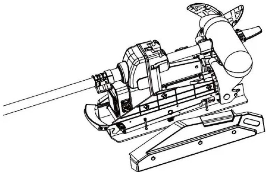
a. Place the mount on an elevated, level surface such as a workbench or t tailgate of a pickup. The motor, as removed from the box, should be in the stowed position.
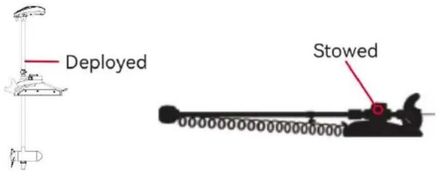
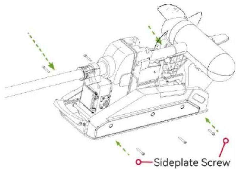
b. Remove the four sideplate screws using a Phillips screwdriver. Two of the screws will be located on each side of the mount.
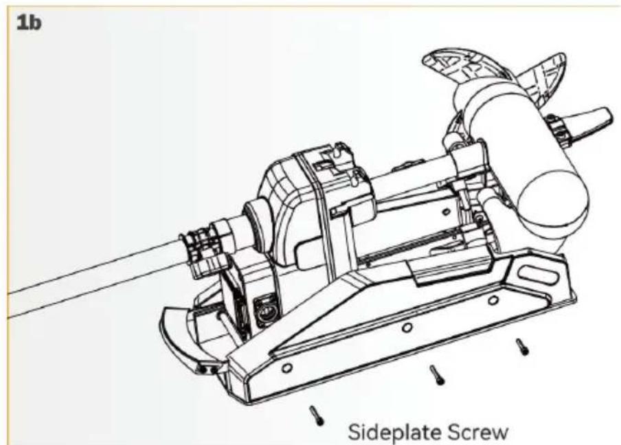
NOTICE: This motor weighs approximately 65lbs.
VEVOR recommends having a second person help with the installation.
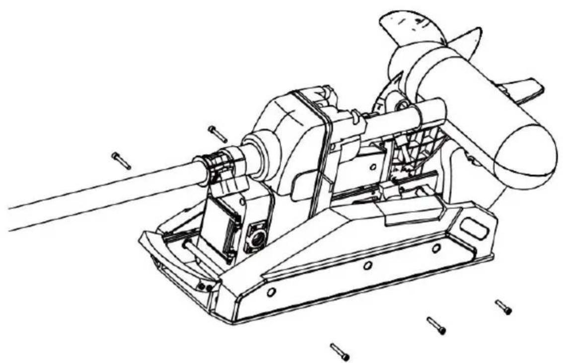
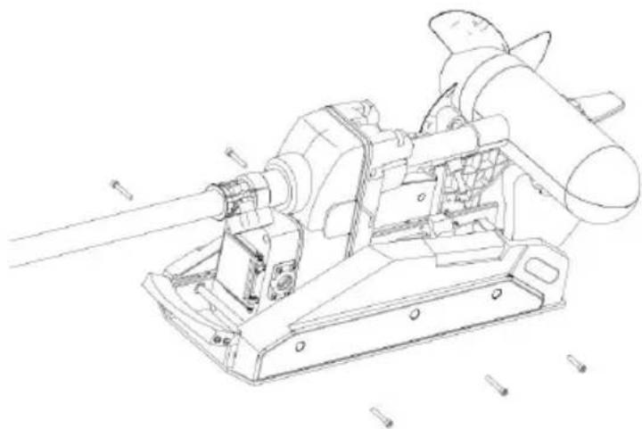
c. Remove the Right Sideplate.
natural_image
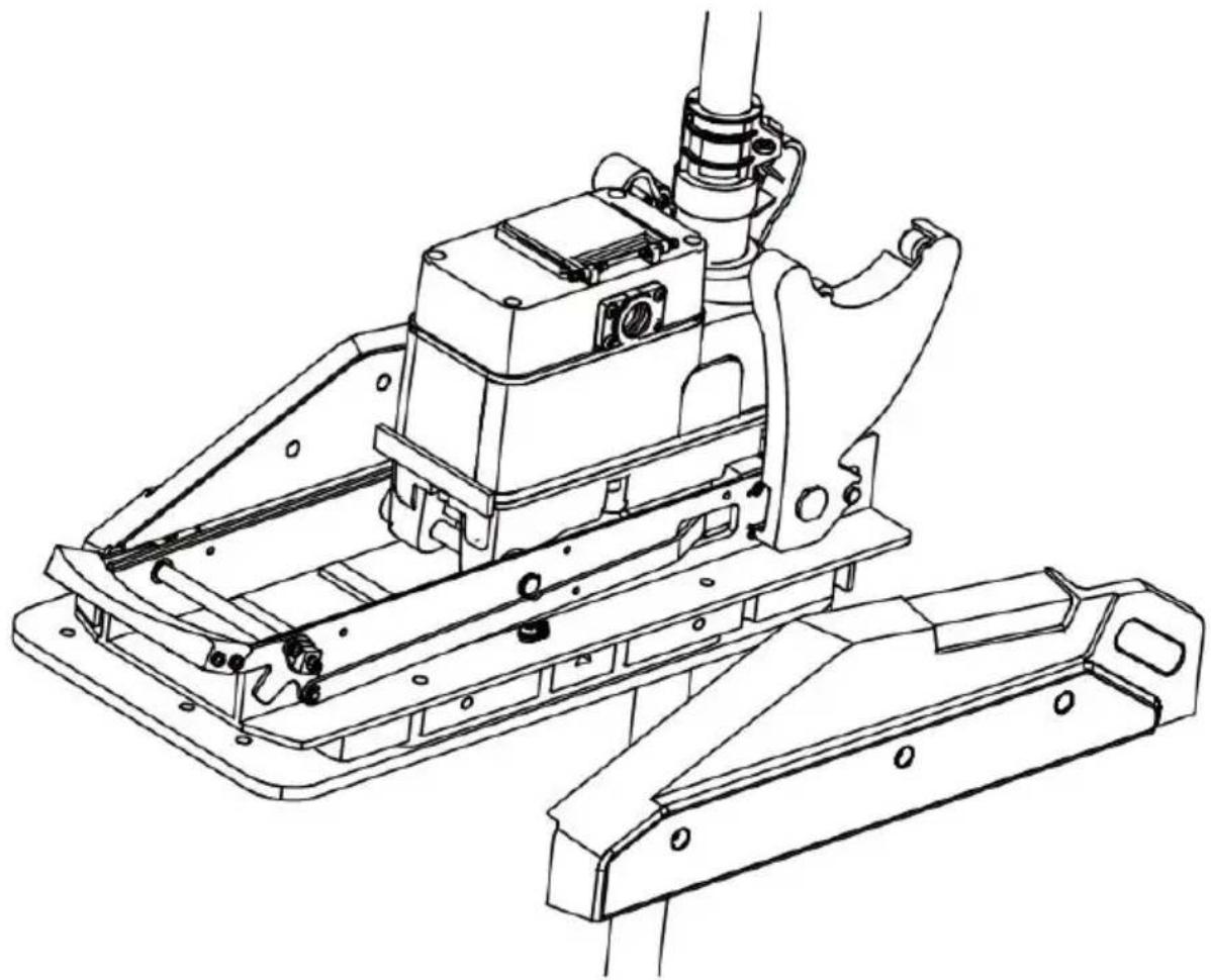
Technical line drawing of a mechanical device with multiple blades and a central shaft (no text or symbols)d. Swing the Left Sideplate out and away from the Base Extrusion.
natural_image
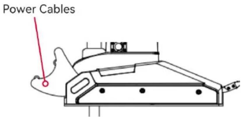
Technical line drawing of a mechanical assembly with frame and housing components (no text or symbols)e.Make sure that the Power Cables from the battery are disconnected, or the breaker, if equipped, is "off."
WARNING!
Make sure the motor is mounted on a level surface and is not connected to power source.
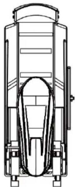
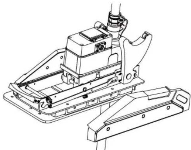
f. Place the mount as close to the centerline or keel of the boat as possible motor can be installed on either the Port or Starboard side of the boat base personal preference. Check placement with the motor in the stowed and deployed positions.
Review the mounting considerations at the beginning of the installation.
natural_image
Technical line drawing of a mechanical device with internal components (no text or symbols)i. It is recommended to mark 4 of the 4 holes in the Base Extrusion. j. Drill through the deck of the boat using a Drill Bit on the marked location
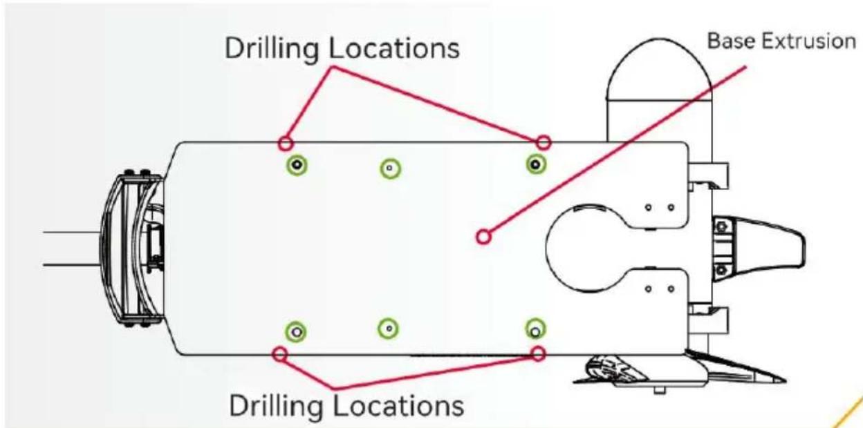
k. Put a screw in each of the drilled locations. The screw should pass through Base Extrusion and the boat deck.
If the rubber washers are used, they should sit between the Base Extrusion boat deck. Make sure to secure the motor with screws on each side of the Extrusion.
I. Place a Flat Washer and then a Nylock Nut at the end of each screw and secure. Make sure all hardware is secure.
natural_image
Technical line drawing of a mechanical device with lever and base mount (no text or symbols)NOTICE: To prevent seizing of the stainless steel hardware, do not use high speed installation tools.
Wetting the screws or applying an anti-seize may help prevent seizing. m. Replace the Right Sideplate.
natural_image
Technical line drawing of a mechanical device with no visible text or symbolsn. Swing the Left Sideplate back into its correct position on the Base Extrusion.
natural_image
Technical line drawing of a mechanical assembly with mounting brackets and a central housing (no text or symbols)o. Replace the four sideplate screws using a Phillips screwdriver. Two these screws will be located on each side of the mount.
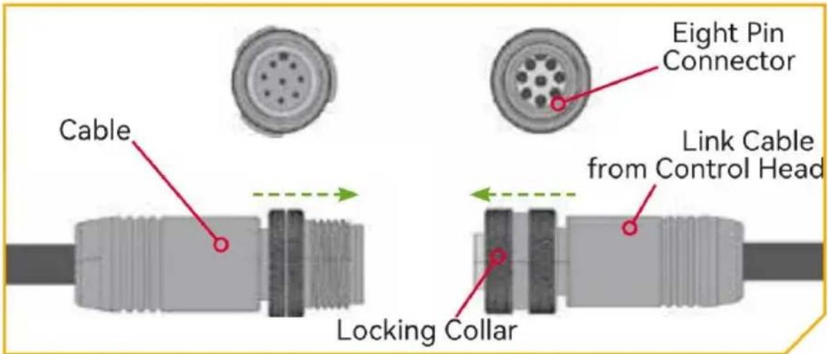
(\*) ROUTING THE LINK CABLE
Your trolling motor may be pre-installed with either Link. To learn more about GPS capabilities available with your Link navigation system, please refer to the corresponding Owner's Manual by visiting www.vevor.com/support.
The Link features require a cable to be connected to an output device. The connection is present on the trolling motor below the Control Head, if installed system does not need an external wired connection. If only one connection is present, your motor is equipped with Link system. If no connections are present your motor may or may not be installed with it. Please follow the MAKO SH recommendations on routing the cables to optimize mobility and maximize functionality. The routing will be the same regardless of the number of cables present. Use the following instructions to properly route cables.
Cables are shielded to minimize interference. To protect this shielding the cables should not be pulled tight against sharp angles or hard objects. If using cable ties, do not over-tighten.
Any excess cable should be bundled in a loose loop of no less than in dia. To minimize trolling motor interference, ensure that the fish finder and trolling motor are powered by separate batteries. Please refer to the Battery & Wirin Installation and Motor Wiring Diagram sections of this manual for correct riggi instructions.
Note: Solely the signal cable interface is designated for the sensor function. Consumers are required to purchase the specific sensor accessories or ensure they are included in the product model. It is not mandatory for the product to include accessories; rather, the physical accessories that consumers purchase shall prevail.
BOAT RIGGING & PRODUCT INSTALLATION
For safety and compliance reasons, we recommend that you follow American Boat and Yacht Council (ABYC) standards when rigging your boat. Altering bo wiring should be completed by a qualified marine technician. The following specifications are for general guidelines only:
CAUTION
These guidelines apply to general rigging to support your Minn Kota motor. Powering multiple motors or additional electrical devices from the same power circuit may impact the recommended conductor gauge and circuit breaker size. If you are using wire longer than that provided with your unit, follow the conductor gauge and circuit breaker sizing table below. If your wire extension length is more than 25 feet, we recommend that you contact a qualified man technician.
CAUTION
An over-current protection device (circuit breaker or fuse) must be used. Coas Guard requirements dictate that each ungrounded current-carrying conductor must be protected by a manually reset, trip-free circuit breaker or fuse. The (voltage and current rating) of the fuse or circuit breaker must be sized accordingly to the trolling motor used. The table below gives recommended guidelines for circuit breaker sizing.
CONDUCTOR GAUGE AND CIRCUIT BREAKER SIZING TABLE
This conductor and circuit breaker sizing table is only valid for the following assumptions:
- No more than 2 conductors are bundled together inside of a sheath of conduit outside of engine spaces.
- Each conductor has 105^ C temp rated insulation.
| Motor Thrust/Mode | Max Amp Draw | Circuit Breaker | Wire Extension Length | ||||
| 5 feet | 10 feet | 15 feet | 20 feet | 25 feet | |||
| 30 lb. | 30 | 50Amp @12VDC | 10 AWG | 10 AWG | 8 AWG | 6 AWG | 4AWG |
| 40 lb.,451b | 42 | 10 AWG | 8 AWG | 6 AWG | 4 AWG | 4 AWG | |
| 50 lb.,55 lb | 50 | 60 Amp @12 VDC | 8 AWG | 6 AWG | 4AWG | 4AWG | 2 AWG |
| 70 lb. | 42 | 50 Amp @24VDC | 10 AWG | 10 AWG | 8 AWG | 8 AWG | 6 AWG |
| 80 lb. | 56 | 60 Amp @24VDC | 8 AWG | 8 AWG | 8 AWG | 6 AWG | 6 AWG |
| 101lb. | 46 | 50 Amp @36VDC | 8 AWG | 8 AWG | 8 AWG | 8 AWG | 8 AWG |
| Engine Mount 101 | 50 | 60 Amp @36 VDC | 8 AWG | 8 AWG | 8 AWG | 8 AWG | 8 AWG |
| 112lb. | 52 | 60 Amp @36VDC | 8 AWG | 8 AWG | 8 AWG | 8 AWG | 8 AWG |
| Engine Mount 160 | 116 | 60 Amp @24 VDC | 6 AWG | 6 AWG | 4 AWG | 2 AWG | 2 AWG |
| E-Driv | 40 | 50 Amp @48 VDC | 10 AWG | 10 AWG | 10 AWG | 10 AWG | 10 AWG |
- No more than 5% voltage drop allowed at full motor power based on published product power requirements.
NOTICE: Wire Extension Length refers to the distance from the batteries to t trolling motor leads. Consult website for available thrust options. Maximum Am Draw values only occur intermittently during select conditions and should not used as continuous amp load ratings.
Reference
United States Code of Federal Regulations: 33 CFR 183 - Boats and Association Equipment ABYC E-11: AC and DC Electrical Systems on Boats
SELECTING THE CORRECT BATTERIES
The motor will operate with any lead acid, deep cycle marine 12 volt battery batteries. For best results, use a deep cycle, marine battery with at least a amp-hour rating. Maintain battery at full charge. Proper care will ensure havin battery power when you need it and will significantly improve the battery life.
Failure to recharge lead-acid batteries (within 12-24 hours) is the leading cause of premature battery failure. Use a multi-stage charger to avoid overcharging. We offer a wide selection of chargers to fit your charging needs. If you are a crank battery to start a gasoline outboard, we recommend that you use a separate deep cycle marine battery/batteries for your VEVOR trolling motor. For more information on battery selection and rigging, please check with related departments.
WARNING
Never connect the (+) and the (-) terminals of the same battery together. Ta care that no metal object can fall onto the battery and short the terminals. would immediately lead to a short and extreme fire danger.
CAUTION
Refer to "Conductor Gauge and Circuit Breaker Sizing Table" in the previous section to find the appropriate circuit breaker or fuse for your motor.
CAUTION
Please read the following information before connecting your motor to your batteries in order to avoid damaging your motor and/or voiding your warranty.
ADDITIONAL CONSIDERATIONS
> Using DC or Alternator Chargers
Your VEVOR trolling motor may be designed with an internal bonding wire to reduce sonar interference. Most alternator charging systems do not account for this bonding wire, and connect the negative posts of the trolling motor batteri to the negative posts of the crank/starting battery. These external connections can damage connected electronics and the electrical system of your trolling motor, voiding your warranty. Review your charger's manual carefully or consu the manufacturer prior to use to ensure your charger is compati-ble.
> Additional Accessories Connected to Trolling Motor Batteries
Significant damage to your VEVOR motor, your boat electronics, and your boat can occur if incorrect connections are made between your trolling motor batteries and other battery systems. VEVOR recommends using an exclusive battery system for your trolling motor. Where possible, accessories should be connected to a separate battery system. Radios and sonar units should not be
connected to any trolling motor battery systems as interference from the trollir motor is unavoidable. If connecting any additional accessories to any trolling motor battery system, or making connections between the trolling motor batteries and other battery systems on the boat, be sure to carefully observe information below. The negative (-) connection must be connected to the nega-tive terminal of the same battery that the trolling motor negative lead connects to. In the diagrams below this battery is labeled "Low Side"
Battery. Connecting to any other trolling motor battery will input positive voltage into the "ground" of that accessory, which can cause excess corrosion. Any damage caused by incorrect connections between battery systems will not be covered under warranty.
The negative (-) connection must be connected to the negative terminal of the same battery that the trolling motor negative lead connects to. In the diagram below this battery is labeled "Low Side" Battery. Connecting to any other trol motor battery will input positive voltage into the "ground" of that accessory, which can cause excess corrosion. Any damage caused by incorrect connections between battery systems will not be covered under warranty.
> Automatic Jump Start Systems and Selector Switches
Automatic jump start systems and selector switches tie the negatives of the connected batteries together. Connecting these systems to the "High Side" Battery or "Middle" Battery in the diagrams below and will cause significant damage to your trolling motor and electronics. The only trolling motor battery that is safe to connect to one of these systems is the "Low Side" Battery.
CONNECTING THE BATTERIES
> 12-Volt Systems
-
Make sure that the motor is switched off (speed selector on "OFF" or Connect positive (+) red lead to positive (+) battery terminal.
-
Connect negative (-) black lead to negative (-) battery terminal.
WARNING
For safety reasons do not switch the motor on until the propeller is in water. If installing a leadwire plug, observe proper polarity and follow instructions in your boat owner's manual.
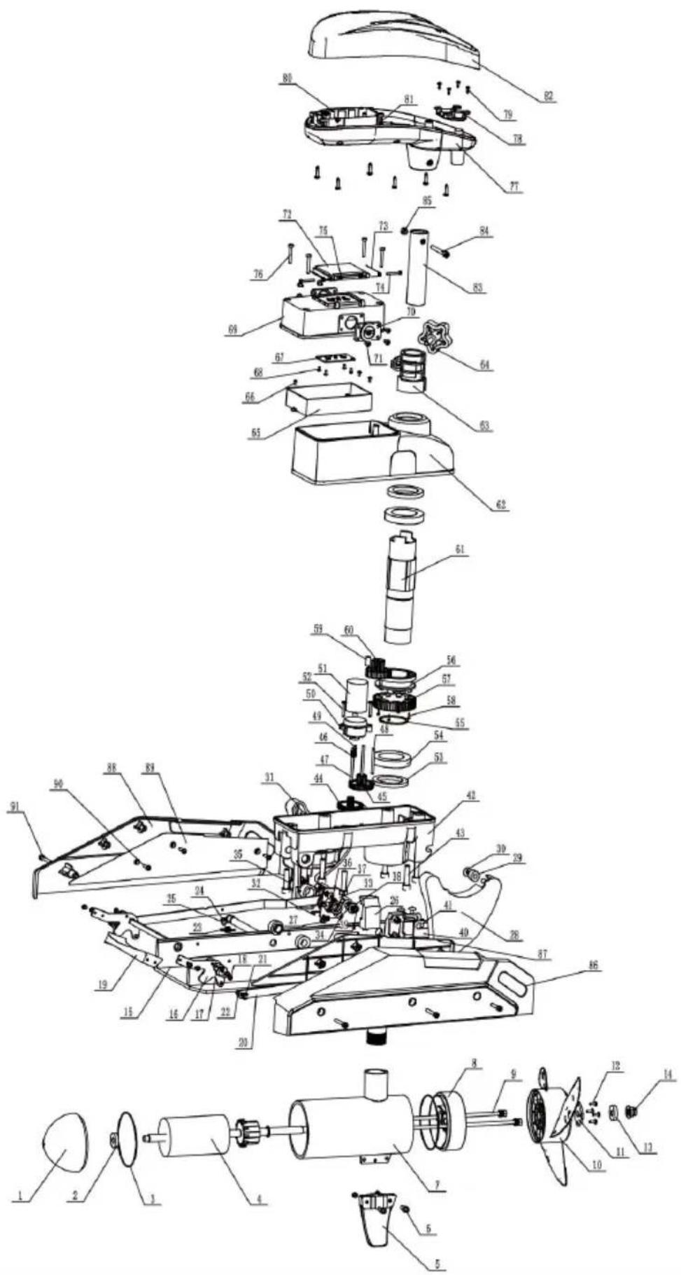
| item | description | quantity | specification |
| 1 | Motor front cover | 1 | |
| 2 | Deep groove ball bearings | 1 | 61900-2RS |
| 3 | Oring seals | 1 | 6*5 |
| 4 | Rotor assembly | 1 | |
| 5 | Fins | 1 | |
| 6 | m5*16 hexagonal bolts | 2 | |
| 7 | Motor barrel | 1 | |
| 8 | Motor backseat | 1 | |
| 9 | m6*232 bolts | 2 | |
| 10 | Propeller | 1 | |
| 11 | Propeller pressure plate | 1 | |
| 12 | Cross recessed pan head tapping screws | 4 | |
| 13 | Anti-corrosion zinc block | 1 | |
| 14 | m10 lock nuts | 1 | |
| 15 | Base plate | 1 | |
| 16 | Pedal support | 2 | |
| 17 | Square shaft cover | 2 | |
| 18 | Cross recessed pan head screws | 18 | M4*6 |
| 19 | Pedal | 1 | |
| 20 | Left and right connecting rods | 1 | |
| 21 | E-Clip | 2 | d5 |
| 22 | Slotted Pins | 2 | |
| 23 | Tension Spring | 2 | |
| 25 | Tension spring spacer | 2 | |
| 26 | Cross recessed large round head screws | 2 | m5*10 |
| 26 | Gearboxleft and right spacers | 1 | |
| 27 | Copper bushing | 2 | |
| 28 | Left and right support plate | 1 | |
| 29 | Pulley | 4 | |
| 30 | Cross recessed pan head screws | 4 | 3.5*9.5 |
| 31 | Lower housing sealing strip | 1 | |
| 32 | Torsion spring | 2 | |
| 33 | Torsion Spring Plate | 2 | |
| 34 | Cross recessed pan head tapping screws | 8 | 3.5*9.5 |
| 35 | M14*1.5 studs | 2 | |
| 36 | Elastic spring for shaft | 4 | |
| 37 | Support plate spacer | 2 | |
| 38 | Igus spacer | 4 | D10*D18*1 |
| 39 | Elastic Circlips for Shaft | 2 | d10 |
| 40 | Fixed wall plate | 2 | |
| 41 | Cross recessed large flat head screws | 4 | 6*8 |
| 42 | Gearboxlower housing | 1 | |
| 43 | Hexagonsocket head cap screws | 6 | 8*35 |
| 44 | Primary reduction gear | 1 | |
| 45 | Secondary reduction gear | 1 |
Manufacturer: Shanghaimuxinmuyeyouxiangongsi
Address: Shuangchenglu 803nong11hao1602A-1609shi, baoshanqu, shanghai 200000 CN.
Imported to AUS: SIHAO PTY LTD. 1 ROKEVA STREETEASTWOOD NSW 2122 Australia
Imported to USA: Sanven Technology Ltd. Suite 250, 9166 Anaheim Place, Rancho Cucamonga, CA 91730
| EC | REP |
E-CrossStu GmbH
Mainzer Landstr.69, 60329 Frankfurt am Main
| UK | REP |
YH CONSULTING LIMITED.
C/O YH Consulting Limited Office 147, Centurion House, London Road, Staines-upon-Thames, Surrey TW18 4AX
VEVOR®
TOUGH TOOLS, HALF PRICE
Technical Support and E-Warranty Certificate
www.vevor.com/support
VEVOR®
TOUGH TOOLS, HALF PRICE
Technical Support and E-Warranty Certificate www.vevor.com/support
Electric Trolling Motor Remote Control Instructions
Model: OMS150S
We continue to be committed to provide you tools with competitive price. "Save Half", "Half Price" or any other similar expressions used by us only represents an estimate of savings you might benefit from buying certain tools with us compared to the major top brands and does not necessarily mean to co all categories of tools offered by us. You are kindly reminded to verify carefully when you are placing an order with us if you are actually Saving Half in comparison with the top major brands.
VEVOR®
TOUGH TOOLS, HALF PRICE
Electric Trolling Moto
Model: OMS150S
natural_image
Technical line drawing of a boat's mast and propeller assembly (no text or symbols)NEED HELP? CONTACT US!
Have product questions? Need technical support? Please feel free to contact us:
Technical Support and E-Warranty Certificate www.vevor.com/support
This is the original instruction, please read all manual instructions care before operating. VEVOR reserves a clear interpretation of our user manual. The appearance of the product shall be subject to the product received. Please forgive us that we won't inform you again if there are technology or software updates on our product.

Warning: To reduce the risk of injury, the user must read the instructions manual carefully.

Comply with the European security certification.
CORRECT DISPOSAL

This product is subject to the provision of european Directive 2012/19/EU.
The symbol showing a wheelie bin crossed through indicates that the product requires separate refuse collection in the European Union.
This applies to the product and all accessories marked with this symbol. Products marked as such may not be discarded with normal domestic wa but must be taken to a collection point for recycling electrical and electro devices.
FCC Information:
CAUTION: Changes or modifications not expressly approved by the party responsible for compliance could void the user's authority to operate the equipment!
This device complies with Part 15 of the FCC Rules. Operation is subject to the following two conditions:
1) This product may cause harmful interference.
2) This product must accept any interference received, including interference that may cause undesired operation.
WARNING: Changes or modifications to this product not expressly approved by the party.
responsible for compliance could void the user's authority to operate the product.
Note: This product has been tested and found to comply with the limits Class B digital device pursuant to Part 15 of the FCC Rules, These limits are designed to provide reasonable protection against harmful
interference in a residential installation.
This product generates, uses and can radiate radio frequency energy, and not installed and used in accordance with the instructions, may cause harmful interference to radio communications. However, there is no guarantee that interference will not occur in a particular installation. If this product does cause harmful interference to radio or television reception, which can be determined by turning the product off and on, the user is encouraged to try to correct the interference by one or more of the following measures.
Reorient or relocate the receiving antenna.
Increase the distance between the product and receiver.
- Connect the product to an outlet on a circuit different from that to whi the receiver is connected.
- Consult the dealer or an experienced radio/TV technician for assistance.
1. Remote Control Instructions
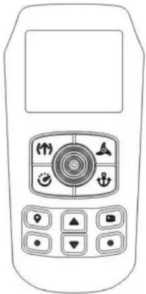
1.1. Remote Control Appearance
natural_image
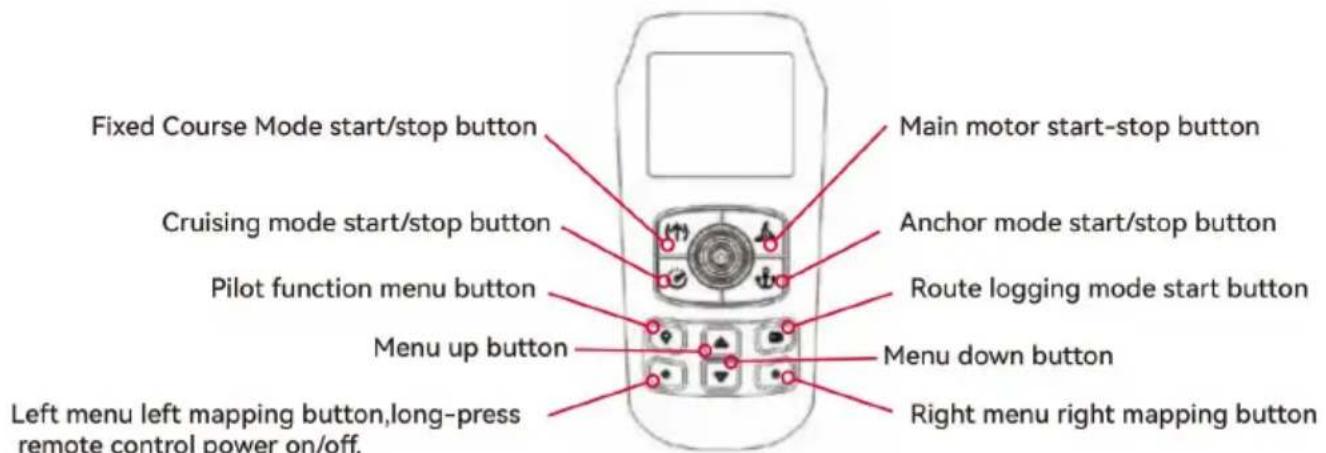
Front view of a mobile phone with control panel and navigation buttons (no text or symbols visible)1.2. Remote Control Directional handle and Instructions of Button function
Directional handle:
push upward: for a single push up, the main motor adds 1 gear; for a co push up, the main motor continuously adds gears
push down: for a single push down, the main motor decreases by 1 gear; continuous push down, the main motor decreases continuously.
Push left: trolling turn left.
Push right: trolling turn right.
Button:

Fixed Course Mode start/stop button.

Main motor start-stop button.

Cruising mode start/stop button.

Anchor mode start/stop button.

Pilot function menu button.

Route logging mode start button.

Menu up button

Menu down button.

Left menu left mapping button, long-press remote control power on/off.

Right menu right mapping button.
1. 3. Pairing the remote control with trolling motor

- In the home page, press the remote control menu up & down button to switch the menu bar at the bottom of the screen to show "Setting" on the left side and "Lock" on the right side.
- Press the left menu button to enter the setting page. Use "Menu Up" and Down" buttons to switch to select "Pairing" menu, press "Menu Right" button to select "Pairing" to enter the pairing page. Press the "Menu Right" button to "Pairing" to enter the pairing page, stay on this page and press the pairing on the trolling motor control board, once you hear five consecutive beeps, the pairing is successful.
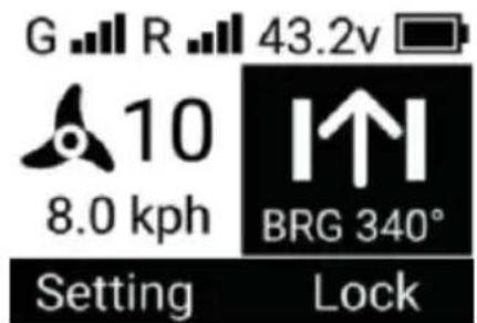
1.4. Remote control screen description display
Top status bar:

GNSS system signal

Remote control signal

trolling motor battery voltage

Remote Control Battery Level
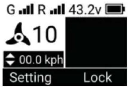
Central operation status bar:

At the main motor of the trolling rotating, the higher the gear, the faster fan blade rotates, and the fan blade will stop rotating when the motor gear is the motor is off.
10
The main motor of trolling motor, can adjust from 0 to 10 gear.
8.0 kph
The current speed of the trolling motor

The current mode of the trolling motor
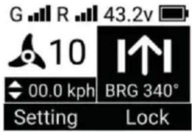
Bottom Menu Bar:
Setting

Lock
Setting: Menu left button mapping, press to enter setting 3 page Lock: Long press to lock remote control buttons
1.5 Screen display in different modes
A. Fixed Course Mode
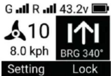
The trolling motor travels in a straight line, keeping the direction the same a
BRG value.
B. Cruising Mode
Trolling motor will be travelling at a speed close to the target speed.
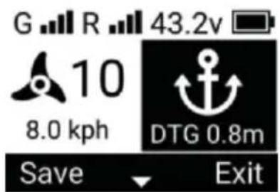
C. Anchor Mode
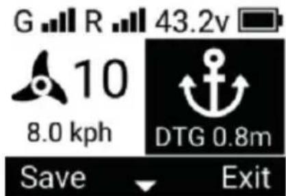
DTG is the distance from the anchorage point
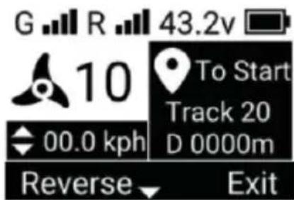
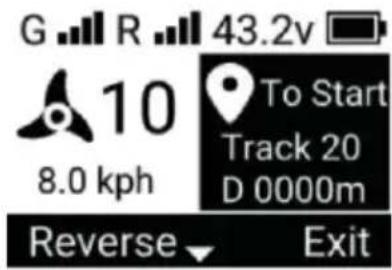
D. Pilot Mode
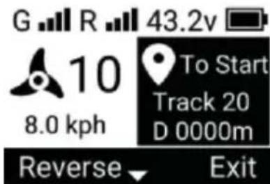
Track is the serial number of the route in the route menu, D is the re distance from the start of the route
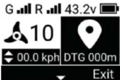
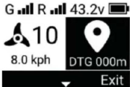
E. Go To Mode
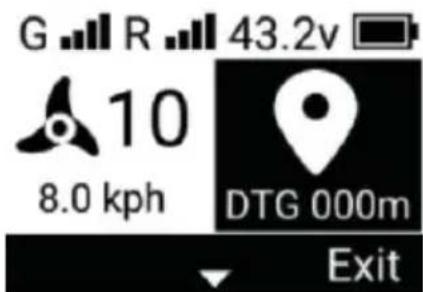
DTG is the distance to destination remaining length/ remaining distance
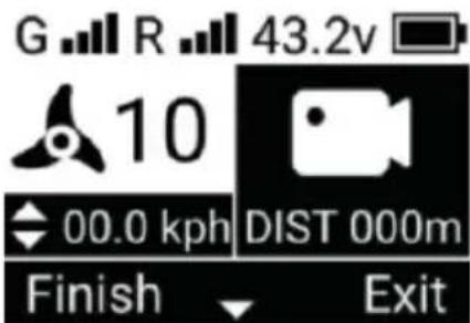
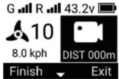
F. Route Logging Mode
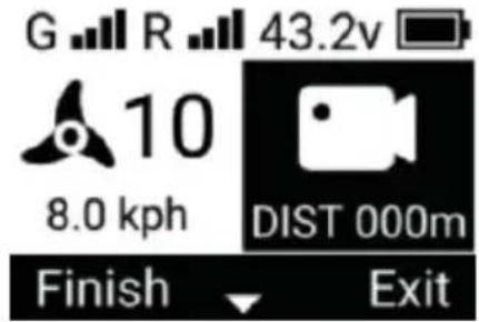
DIST is the recorded course distance.
G. Turn on "Cruise Mode" and "Fixed Course Mode" at the same tin
H. Turn on “Cruise Mode” and “Pilot Mode” at the same time.
I. Turns on "Cruise Mode" & "Go To Mode" at the same time.
J. Turn on "Cruise Mode" and "Record Course Mode" at the same time.
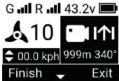
K. Turn on "Record Course Mode" and "Fixed Course Mode" at the sam

L. Turn on "Record Course Mode", "Cruise Mode" and "Fixed Course Mode" at the same time.
1.6. Remote Control Charge
Remove the cover of the charging Interface on the bottom of the remote con charging.
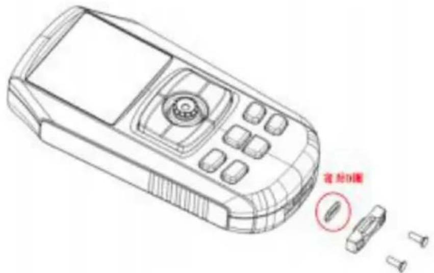
| Interface Type | Type-c |
| Charging Voltage | 5V |
| Charging current | IA |
Attention: Lock the charging port cover back after charging and make sure the O-ring is on the cover.
2. Trolling Motor Operating Mode
2.1. Fixed Course Mode
Press the remote control's "Fixed Course start / stop " button to turn on the Course Mode".
- When this mode is activated, the trolling motor travels in a straight line in current ship control direction.
- This mode can be activated in [Cruise Mode] and [Record Route Mode], a of the above modes can be used in parallel with this mode.
- This mode cannot be turned on in [ Go To Model ], [ Pilot Model ] and Mode ].
- Press the "Fixed Course Mode Start/Stop" button again to exit "Fixed Course Mode "
Change of course to fixed direction
In "Fixed Course Mode" remote control handle "Push Left" and "Push Right" buttons can change the direction of trolling motor travelling in a straight line.
2.2. Cruise Mode
Press the "Cruise Start/Stop" button on the remote control to switch on "Cruise Mode".
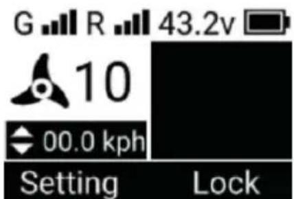
- When this mode is activated, the trolling motor travels at the current speed recording the current speed as the target speed
- This mode can be activated in 'Bow Fix Mode', 'Fixed Course Mode', 'Record Course Mode', 'Route Mode' and 'Go To Mode', and all of the above modes be used in parallel with this mode.
- This mode cannot be turned on in [Anchor Model .
- Press the remote control "Cruise mode start/stop" button again to exit "Crui mode"
Change of target speed:
In "Cruise Mode" the remote control directional handle "Push Up" and "Push Down" button can change the target speed of the trolling motors.
- Remote control directional handle single push up, target speed + 0.2 kph
- Remote control directional handle single push down, target speed - 0.2 kp
2.3. Anchor mode
Press the "anchor start/stop" button on the remote control to activate "anchor mode"
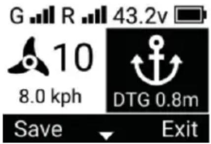
- When this mode is activated, the motors are automatically switched on and trolling motors anchor in the coordinates of the instant the command is received
- This mode can be activated in "Bow Fix Mode", "Fixed Course Mode « Mode"
- It is invalid to activate this mode in "Record Route Mode", "Pilot Mode" and To Mode"
- In this mode, manual steering control of the motor is not effective.
- Turning the motor off in this mode restores steering control to the motor.
- Press the remote control "anchor" button again to exit "anchor mode"
2.4.Pilot model
Press the "Pilot Function Menu"
button on the remote control to enter the Navigation page, and then select Track to enter the Navigation-Track page. Select a stored route location, press "Menu Left" button to select To Start / To End to open "Pilot Mode"
-
When this mode is activated, the motors are automatically switched on and trolling motors follow a set course.
• There are two options at startup. -
To Start, from the "end" of the route to the "beginning" of the route.
- To End, from the "Start" to the "End" of the route.
Whichever of the above models is used, it starts from the closest point of the
• This mode can be activated in Fixed
Course Mode " "Cruise Mode", and 'Go To Mode', and 'Cruise Mode' can be in parallel with this mode.
- It is invalid to activate this mode in "Record Course Mode" and "Anchor M
- Exit in the menu bar at the bottom of the screen to exit "Pilot Mode".
reverse course:
In "Pilot Mode", press the remote control menu up & down buttons to switch menu bar at the bottom of the screen to Reverse on the left side and Exit right side. Press "Menu Left Mapping" button to reverse the route, after rever the route, the To Start on the screen will change to To End, and vice vers
2.5. Go To mode
Press the "Pilot Function Menu" button on the remote control to enter the Navigation page, and then select Spot to enter the Navigation-Spot page. Self-stored waypoint location and press "Menu Left" button to open "Go To Mode
- When this mode is activated, the motors are automatically switched on and trolling motors travel in a straight line to the target waypoint.
- This mode can be activated in 'Heading Fixed Mode', 'Cruise Mode' and
Mode', and 'Cruise Mode' can be used in parallel with this mode.
- It is invalid to activate this mode in "Record Course Mode" and "Anchor M
- Automatically switch on "Anchor Mode" when you reach the target waypoint.
- Exit in the menu bar at the bottom of the screen to exit "Go To Mode".
2.6. Recording route patterns
Press the "Menu Right Mapping" button to activate "Record Route Mo
- When this mode is activated, the boat control can record the sailing track.
- This mode can be activated in [Manual Mode], [Bow Fixed Model], [Fixed Mode] and [Cruise Mode], and all of the above modes can be used parallel with this mode.
- This mode cannot be turned on in 'Pilot Mode', 'Go To Mode' and 'Ancho
- The maximum distance of the recorded route is 5 kilometres, over 5 kilometers, the remote control will automatically save the recorded route and exit the "Course Mode"
- Exit from the menu bar at the bottom of the screen to exit "Record Course
Record-keeping routes
In "Record Course Mode", press the remote control menu up & down buttons toggle the menu bar at the bottom of the screen to show Finish on the left on the right. Press the "Menu Left Mapping" button to exit the Record Route and save the route to the remote control.
3. Trolling motor buttons, indicator lights, beeps
3.1. Trolling Motor buttons
On/off buttons
- Press the button in the off state to start the motor
- Press and hold the button for 3s to shut down the motor
Pairing/Anchoring Buttons
- Press and hold the button for 2s and the motor will emit three beeps to enter the pairing mode, at this time, make the remote control also enter the pairing mode to be paired successfully.
- Short press of the button turns the motor on in anchoring mode, press a exit anchoring mode
3.2. power display
4 green lights indicate the amount of electricity
| Voltage | Number of lights on |
| V>12.5V | 4 |
| 11.8V3 | 3 |
| 11.4V2 | 2 |
| 10.8V1 | 1 |
| V<10.8V | 1(flickering) |
3.3. Status and Tips
3.3.1. Status indicators
- Startup in progress: indicator
- Idle state(no GPS located): indicator yellow.
- Idle state(GPS located): indicator green.
- Running status(motor on): Indicator blue.
- Warning Status:Indicator light yellow.
- Error status: Indicator light is red.
3.3.2. Pairing Tips
| CUE | beep | indicator light |
| Remote control not connected | none | Green light flashing slowly. |
| Remote control pairing progress | Three consecutive beeps the start of the pairing. | The green light is flashing fast. |
| Remote control paired successfully | Five consecutive beeps a the moment of successful pairing. | Display by other statu |
3.3.3.Normal Alerts
In the normal state, the purpose is to signal the user that the operation was successful or has responded.
| CUE | beep |
| Increase or decrease motor gear(motor on) | Single beep |
| On/Off Motor | |
| Start or stop anchoring, pilotage, cruising, heading logging course mode |
3.3.4. Warning notices
In a warning state, but the thruster is currently operational and requires the immediately address or be aware of the current operation.
| CUE | beep and indicator light | solution | note |
| Motor battery voltage is too high | Continuous triple beeps Yellow light blinks fast | Operating voltage too high For 12V propeller please ensure that the supply voltage is <18V | |
| Motor battery voltage is too low | Continuous double beeps Yellow light flashing slowly | Operating voltage too low. For 12V propeller please ensure that the supply voltage is >10V | |
| Motor current is too large | Continuous double beeps Fast flashing yellow light | Cleaning of foreign objects wrapped around the motor propeller | • Alarm starts when current exceeds 60A• High currentalarm for more than 1 minute, switch off the motorWhen the current exceeds 70A, the motor immediately switched off. |
| Steering motor error | Continuous triple beeps Yellow light flashing fa | Spring wire is jammed please untwist it | Alarm starts when steering motor current exceeds 1.0A |
| Driver temperature is to high | Continuous double beeps Yellow light flashing slowly | he internal temperature of the drive is too high please turn off the motor, and ensure that there is no obstruction around the drive, ventilation is normal | Alarm starts when the temperature exceeds 70°C, and the motor is switched off after the temperature alarm lasts for 2 minutes.Immediately shuts down the motor when the temperature exceeds 80°C |
| △ Motor error | Continuous triple beeps Yellow light blinks fast | Main motor current exceeds threshold, check if propeller is jammed | 118A |
3.3.5.Error Alerts
In the error state, the trolling motor components are damaged and no longer function properly.
| CUE | beep and indicator light | solution | note |
| ☒ Gyroscope error | Continuous single beep Red light flasheslowly | Recalibrating the gyroscope using the remote control | |
| ☒ Accelerometer error | Recalibrating the accelerometer using the remote control | ||
| ☒ Mag overbias | Keep away from magnetic objects | ||
| × Mag overflow | Keep away from magnetic objects | ||
| ☒ Mag data timeout | from magnetic object | ||
| ☒ GPS module error | GPS module error,please try to restart the trolling motor | ||
| ☒ System power supply error | Boat control power supply error, repair required | ||
| ☒ Sensor error | Boat control transducer error, repair required |
3.3.6. Other tips
In other states, the trolling motor is no longer functioning properly and require immediate attention from the user.
| abnormal phenomenon | solution | note |
| Lamp board red light flas slowly | Boat control panel tilted mo than 80°, please place it horizontally. | |
| Lamp board white light flashing slowly | Broken spring wire or loos socket |
4. External Sensors
4.1.Indicators
- Normal operation: green light flashes slowly
- The angle of inclination is too large: the green light flashes fast.
- Communication disconnected: red light flashes slowly.
- Sensor error: Red light flashes fast.
4.2. Spring wire Anti-tangle
In non-manual mode, if the spring line is wound more than one turn, trigger anti-tangle, the motor will turn off temporarily, the boat control will automatic rotate to unwind, and finally return to the angle when the anti-tangle was trig and the motor will turn on automatically when it is finished.
4.3. Anchor panning
Push the handle left, right, up and down on the anchor mode remote.
- Single left push: the anchor point is moved 1 metre to the left relative to external sensor is pointing.
- Single right push: the anchor point is moved 1 metre to the right relative to the external sensor is pointing.
- Single upward thrust: the anchor point is moved forward 1 metre relative to where the external sensor is pointing.
- Single push down: anchor point moves 1 metre backwards relative to the pointing of the external sensor
Manufacturer: Shanghaimuxinmuyeyouxiangongsi
Address: Shuangchenglu 803nong11hao1602A-1609shi, baoshanqu, shanghai 200000 CN.
Imported to AUS: SIHAO PTY LTD. 1 ROKEVA STREETEASTWOOD NSW 2122 Australia
Imported to USA: Sanven Technology Ltd. Suite 250, 9166 Anaheim Place, Rancho Cucamonga, CA 91730
| EC | REP |
E-CrossStu GmbH
Mainzer Landstr.69, 60329 Frankfurt am Main
| UK | REP |
YH CONSULTING LIMITED.
C/O YH Consulting Limited Office 147, Centurion House, London Road, Staines-upon-Thames, Surrey TW18 4AX
VEVOR®
TOUGH TOOLS, HALF PRICE
Technical Support and E-Warranty Certificate
www.vevor.com/support
VEVOR®
TOUGH TOOLS, HALF PRICE
natural_image
Technical line drawing of a boat's propeller and mast assembly (no text or symbols)BESOIN D'AIDE? CONTACTEZ-NOUS!
INSTALLATION
natural_image
Technical line drawing of a mechanical device with no visible text or symbolsnatural_image
Technical line drawing of a mechanical assembly with frame and housing components (no text or symbols)AVERTISSEMENT!
natural_image
Technical line drawing of a mechanical device with internal components and no visible text or symbolsnatural_image
Technical line drawing of a mechanical device with no visible text or symbolsnatural_image
Technical line drawing of a mechanical device with no visible text or symbolsnatural_image
Technical line drawing of a mechanical assembly with frame and housing components (no text or symbols)A/S YH Consulting Limited Bureau 147, Centurion
Maison, London Road, Staines-upon-Thames, Surrey, TW18 4AX
VEVOR®
TOUGH TOOLS, HALF PRICE
natural_image
Line drawing of a vertical electric motor with propeller and fan (no text or symbols)BESOIN D'AIDE? CONTACTEZ-NOUS!
natural_image
Line drawing of a mobile phone control panel with navigation buttons and function icons (no text or labels)A/S YH Consulting Limited Bureau 147, Centurion
Maison, London Road, Staines-upon-Thames, Surrey, TW18 4AX
VEVOR®
TOUGH TOOLS, HALF PRICE
natural_image
Technical line drawing of a boat's propeller and mast assembly (no text or symbols)INSTALLATION
www.vevor.com/support.
LISTE DER INSTALLATIONSTEILE
natural_image
Technical line drawing of a mechanical device with no visible text or symbolsnatural_image
Technical line drawing of a mechanical assembly with frame and housing components (no text or symbols)WARNUNG!
natural_image
Technical line drawing of a mechanical device with internal components and no visible text or symbolsnatural_image
Technical line drawing of a mechanical device with no visible text or symbolsnatural_image
Technical line drawing of a mechanical device with no visible text or symbolsnatural_image
Technical line drawing of a mechanical assembly with frame and housing components (no text or symbols)C/O YH Consulting Limited Office 147, Centurion
Haus, London Road, Staines-upon-Thames, Surrey, TW18 4AX
VEVOR®
TOUGH TOOLS, HALF PRICE
www.vevor.com/support
VEVOR®
TOUGH TOOLS, HALF PRICE
natural_image
Line drawing of a vertical electric motor with propeller and fan (no text or symbols)natural_image
Line drawing of a mobile phone control panel with function buttons and navigation icons (no text or labels)C/O YH Consulting Limited Office 147, Centurion Haus, London Road, Staines-upon-Thames, Surrey, TW18 4AX
VEVOR®
TOUGH TOOLS, HALF PRICE
www.vevor.com/support
VEVOR®
TOUGH TOOLS, HALF PRICE
natural_image
Technical line drawing of a boat's propeller and mast assembly (no text or symbols)INSTALLAZIONE
www.vevor.com/support.
ELENCO DELLE PARTI DI INSTALLAZIONE
natural_image
Technical line drawing of a mechanical device with no visible text or symbolsnatural_image
Technical line drawing of a mechanical assembly with frame and housing components (no text or symbols)AVVERTIMENTO!
natural_image
Technical line drawing of a mechanical device with internal components (no text or symbols)natural_image
Technical line drawing of a mechanical surveying instrument with no visible text or symbolsnatural_image
Technical line drawing of a mechanical device with no visible text or symbolsnatural_image
Technical line drawing of a mechanical assembly with frame and mounting bracket (no text or symbols)Importato in AUS: SIHAO PTY LTD. 1 ROKEVA STREETEASTWOOD
Nuovo Galles del Sud 2122 Australia
Importato negli USA: Sanven Technology Ltd. Suite 250, 9166 Anaheim
Luogo, Rancho Cucamonga, CA 91730
C/O YH Consulting Limited Ufficio 147, Centurion
Casa, London Road, Staines-upon-Thames, Surrey, TW18 4AX
VEVOR®
TOUGH TOOLS, HALF PRICE
elettronica www.vevor.com/support
VEVOR®
TOUGH TOOLS, HALF PRICE
natural_image
Line drawing of a vertical electric motor with propeller and fan (no text or symbols)www.vevor.com/support
natural_image
Line drawing of a mobile phone control panel with navigation buttons and function icons (no text or labels)Importato in AUS: SIHAO PTY LTD. 1 ROKEVA STREETEASTWOOD
Nuovo Galles del Sud 2122 Australia
C/O YH Consulting Limited Ufficio 147, Centurion
Casa, London Road, Staines-upon-Thames, Surrey,
Modello TW18 4AX
VEVOR®
TOUGH TOOLS, HALF PRICE
elettronica www.vevor.com/support
VEVOR®
TOUGH TOOLS, HALF PRICE
natural_image
Technical line drawing of a boat's propeller and mast assembly (no text or symbols)INSTALACIÓN
www.vevor.com/support.
natural_image
Technical line drawing of a mechanical device with no visible text or symbolsnatural_image
Technical line drawing of a mechanical assembly with frame and housing components (no text or symbols)¡ADVERTENCIA!
natural_image
Technical line drawing of a mechanical device with internal components (no text or symbols)natural_image
Technical line drawing of a mechanical surveying instrument with no visible text or symbolsnatural_image
Technical line drawing of a mechanical device with no visible text or symbolsnatural_image
Technical line drawing of a mechanical assembly with frame and mounting bracket (no text or symbols)Casa, London Road, Staines-upon-Thames, Surrey, TW18 4AX
VEVOR®
TOUGH TOOLS, HALF PRICE
natural_image
Line drawing of a vertical electric motor with propeller and fan (no text or symbols)natural_image
Line drawing of a mobile phone control panel with function buttons and navigation icons (no text or labels)C/O YH Consulting Limited Oficina 147, Centurion Casa, London Road, Staines-upon-Thames, Surrey, TW18 4AX
VEVOR®
TOUGH TOOLS, HALF PRICE
natural_image
Technical line drawing of a boat's propeller and mast assembly (no text or symbols)POTRZEBUJESZ POMOCY? SKONTAKTUJ SIĘ Z NAMI!
INSTALACJA
natural_image
Technical line drawing of a mechanical device with no visible text or symbolsnatural_image
Technical line drawing of a mechanical assembly with frame and housing components (no text or symbols)OSTRZEŻENIE!
natural_image
Technical line drawing of a mechanical device with internal components (no text or symbols)natural_image
Technical line drawing of a mechanical device with no visible text or symbolsnatural_image
Technical line drawing of a mechanical device with no visible text or symbolsnatural_image
Technical line drawing of a mechanical assembly with frame and mounting bracket (no text or symbols)INSTALACJA AKUMULATORA I OKABLOWANIA
C/O YH Consulting Limited Biuro 147, Centurion
Dom, London Road, Staines-upon-Thames, Surrey, TW18 4AX
VEVOR®
TOUGH TOOLS, HALF PRICE
natural_image
Line drawing of a vertical electric motor with propeller and fan (no text or symbols)POTRZEBUJESZ POMOCY? SKONTAKTUJ SIĘ Z NAMI!
natural_image
Line drawing of a mobile phone control panel with navigation buttons and icons (no text or labels)C/O YH Consulting Limited Biuro 147, Centurion
Dom, London Road, Staines-upon-Thames, Surrey, TW18 4AX
VEVOR®
TOUGH TOOLS, HALF PRICE
natural_image
Technical line drawing of a mechanical powertrain with propeller and motor (no text or symbols)HULP NODIG? NEEM CONTACT MET ONS OP!
INSTALLATIE
natural_image
Technical line drawing of a mechanical device with no visible text or symbolsnatural_image
Technical line drawing of a mechanical assembly with frame and housing components (no text or symbols)WAARSCHUWING!
natural_image
Technical line drawing of a mechanical device with internal components (no text or symbols)natural_image
Technical line drawing of a mechanical device with no visible text or symbolsnatural_image
Technical line drawing of a mechanical device with no visible text or symbolsnatural_image
Technical line drawing of a mechanical assembly with frame and mounting bracket (no text or symbols)C/O YH Consulting Limited Kantoor 147, Centurion
Huis, London Road, Staines-upon-Thames, Surrey, TW18 4AX
VEVOR®
TOUGH TOOLS, HALF PRICE
Technische ondersteuning en e-garantiecertificaat www.vevor.com/support
VEVOR®
TOUGH TOOLS, HALF PRICE
Technische ondersteuning en e-garantiecertificaat www.vevor.com/support
natural_image
Line drawing of a vertical electric motor with propeller and fan (no text or symbols)HULP NODIG? NEEM CONTACT MET ONS OP!
natural_image
Line drawing of a mobile phone control panel with function buttons and navigation icons (no text or labels)Bovenste statusbalk:

GNSS-systeemsignaal

C/O YH Consulting Limited Kantoor 147, Centurion Huis, London Road, Staines-upon-Thames, Surrey, TW18 4AX
VEVOR®
TOUGH TOOLS, HALF PRICE
garantiecertificaat www.vevor.com/support
VEVOR®
TOUGH TOOLS, HALF PRICE
natural_image
Technical line drawing of a vertical electric motor with propeller and fan (no text or symbols)BEHÖVER HJÄLP? KONTAKTA OSS!
INSTALLATION
www.vevor.com/support.
INSTALLATIONSDELLISTA
| Artikel/montering | Beskrivning | Antal. |
| 1 | Fjärrkontroll | 1 |
| 2 | Extern sensor (valfritt) | 1 |
| 3 | Propeller | 1 |
| 4 | M10 mutter | 1 |
| 5 | M15 sexkantnyckel | 1 |
| 6 | Tills | 1 |
| 7 | M5*16 insexskruvar | 2 |
| 8 | M5 mutter | 2 |
| 9 | M6*16 insexskruvar | 4 |
| 10 | packningar | 1 |
| 11 | M6*25 insexskruv | 12 |
| 12 | M6 mutter | 4 |
| 13 | Snabbfäste i plast | 1 |
natural_image
Technical line drawing of a mechanical device with no visible text or symbolsnatural_image
Technical line drawing of a mechanical assembly with frame and housing components (no text or symbols)WARNING!
natural_image
Technical line drawing of a mechanical device with internal components (no text or symbols)natural_image
Technical line drawing of a mechanical surveying instrument with no visible text or symbolsnatural_image
Technical line drawing of a mechanical device with no visible text or symbolsnatural_image
Technical line drawing of a mechanical assembly with frame and mounting bracket (no text or symbols)C/O YH Consulting Limited Office 147, Centurion
House, London Road, Staines-upon-Thames, Surrey, TW18 4AX
VEVOR®
TOUGH TOOLS, HALF PRICE
www.vevor.com/support
VEVOR®
TOUGH TOOLS, HALF PRICE
natural_image
Line drawing of a vertical electric motor with propeller and fan (no text or symbols)BEHÖVER HJÄLP? KONTAKTA OSS!
natural_image
Line drawing of a mobile phone control panel with function buttons and navigation icons (no text or labels)Fixed Course Mode start/stopp-knapp.

C/O YH Consulting Limited Office 147, Centurion
House, London Road, Staines-upon-Thames, Surrey, TW18 4AX
VEVOR®
TOUGH TOOLS, HALF PRICE
www.vevor.com/support