MX-S1170 - Metal Lathe Vevor - Free user manual and instructions
Find the device manual for free MX-S1170 Vevor in PDF.

| Product type | Metal lathe |
| Brand | Vevor |
| Model | MX-S1170 |
| Dimensions (package) | 1490 x 515 x 555 mm |
| Net weight | 87.6 kg |
| Power supply | 230 V, 50 Hz (or 110 V, 60 Hz depending on version) |
| Motor power | 1.25 kW |
| Output torque | 4.5 Nm at 850 rpm |
| Spindle speed | 0 - 2500 rpm |
| Spindle bore | 3.8 mm, MT5 taper |
| Chuck size | 125 mm |
| Carriage travel | 1000 mm |
| Allowable diameter (on bed) | 220 mm |
| Metric threading | Pitch from 0.5 to 3 mm |
| Inch threading | 4 to 40 TPI |
| Spindle type | Brushless DC, direct drive |
| Stepper motor | 86-8.5 Nm |
| Main functions | Automatic threading, manual movement, automatic reciprocation, system configuration |
| Maintenance | Cleaning after each use, lubrication with NLGI 2 grease |
| Safety | Emergency stop, mandatory grounding, personal protective equipment |
| Spare parts | Contact the manufacturer via www.vevor.com/support |
| General information | 262-page user manual, available in multiple languages |
Frequently Asked Questions - MX-S1170 Vevor
User questions about MX-S1170 Vevor
0 question about this device. Answer the ones you know or ask your own.
Ask a new question about this device
Download the instructions for your Metal Lathe in PDF format for free! Find your manual MX-S1170 - Vevor and take your electronic device back in hand. On this page are published all the documents necessary for the use of your device. MX-S1170 by Vevor.
USER MANUAL MX-S1170 Vevor
Technical Support and E-Warranty Certificate www.vevor.com/support
METAL LATHE USER MANUAL
MODEL:MX-S450/MX-S1170
We continue to be committed to provide you tools with competitive price. "Save Half", "Half Price" or any other similar expressions used by us only represents an estimate of savings you might benefit from buying certain tools with us compared to the major top brands and does not necessarily mean to co all categories of tools offered by us. You are kindly reminded to verify carefully when you are placing an order with us if you are actually Saving Half in comparison with the top major brands.
MODEL:MX-S450/MX-S1170
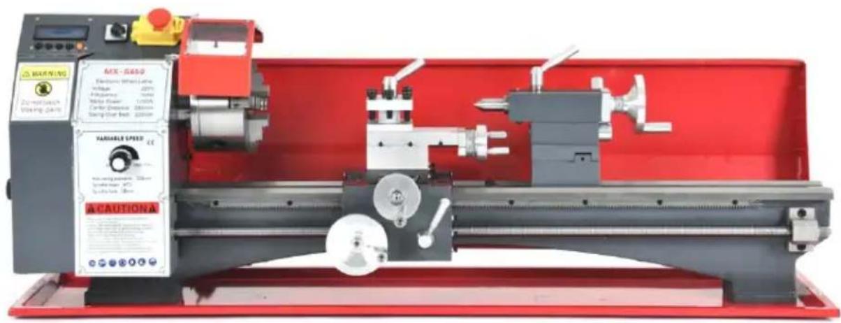
(The picture is for reference only, please refer to the actual object)
NEED HELP? CONTACT US!
Have product questions? Need technical support? Please feel fr contact us:
Technical Support and E-Warranty Certificate www.vevor.com/support
This is the original instruction, please read all manual instruction carefully before operating. VEVOR reserves a clear interpretation user manual. The appearance of the product shall be subject to product you received. Please forgive us that we won't inform you there are any technology or software updates on our product.
| Warning-To reduce the risk of injury, user must read instructio manual carefully. | |
| This product is subject to the provision of European Directive 2012/19/EC. The symbol showing a wheelie bin crossed through indicates that the product requires separate refuse collection in European Union. This applies to the product and all accessory marked with this symbol. Products marked as such may not discarded with normal domestic waste, but must be taken to collection point for recycling electrical and electronic devices |
Safety Information
Workspace Safety
- Keep the work area clean and well lit. Cluttered or dark areas invite accid
- DO NOT allow individuals unfamiliar with this product to use it. Keep children and bystanders away while using this product.
- Ensure that this machine is anchored on a stable, level, and hefty surface before beginning operation.
- DO NOT operate this device in the presence of any explosive, flammable, or caustic liquids, gases, or dust.
Electrical Safety
- ONLY use this machine with stable compatible power sources.
- ALWAYS make sure the power switch is off before plugging in this device.
- Do not use this device if the power switch does not steadily turn it on or off. Repair or replace the damaged component before further use.
- Avoid body contact with grounded surfaces such as pipes, radiators, ranges and refrigerators while using this device.
-
Do not expose the electrical components to water, including rain or excess humidity.
-
This device MUST be electrically grounded for safe use. DO NOT remove grounding prong, modify the plug in any way, or use any adapter plugs.
- Keep the power cord away from heat, oil, sharp edges, or moving parts.
Personal Safety
- DO NOT use this device while you are tired or under the influence of drug alcohol, or medication.
- Always wear appropriate personal protective equipment, such as a dust mask or a hard hat, goggles, nonskid safety shoes, and ear plugs when using this machine.
- DO NOT overreach. Keep proper footing and balance at all times.
- DO NOT wear jewellery or loose clothing and tie back long hair during operation. Keep your clothing, hair, and gloves away from moving parts.
- Remove any adjusting keys or spanners before turning the device on.
- People with pacemakers should consult their physician before using this device. Electromagnetic fields in close proximity to a pacemaker can cause interference and even failure.
Lathe Use and Care
- DO NOT change gears while the machine is in operation.
- DO NOT force this device. Clean and lubricate as needed if parts begin to move slowly.
- Disconnect the power cord plug from the power source before making any adjustments, changing accessories, or storing the device.
- Use only accessories that are recommended by the manufacturer for your model.
- Never leave the device unattended when it is plugged in to an electrical c
- Maintain all labels and nameplates on the device. If any come loose or become illegible, replace them before further use.
Maintenance Safety
- Always unplug the mini lathe from its electrical outlet before performing any inspection, maintenance, or cleaning procedures.
- Maintain this product. Check for misalignment or binding of parts, breakage parts, or any other condition that may affect the device's operation. If da is detected, have the part repaired or replaced before further use.
- Maintain tools with care. Keep cutting tools sharp and clean.
- Service for this device must be performed only by qualified repair personnel
- Store this device and its components out of reach of children and other untrained persons.
Symbol Guide
The following symbols are used on this machine's labeling or in this manual:

These items present a risk of serious property damage or personal injury. These components pose a risk of electric shock. Read the Electrical Safety section above carefully.

Read this manual completely before using this machine. Contact customer service if you have any questions before use.

Always ensure this machine is electrically grounded to prevent electrical shock. Disconnect this machine from its power source before servicing.

Always wear eye protection while using this machine.

Always wear ear protection while using this machine.

Always wear hand protection while using this machine. Take care that well fitted and cannot be caught by a turning workpiece.

Always wear foot protection while using this machine. Rubber-soled steel-toed boots are highly recommended.

Always wear head protection while using this machine. Use a hard hat similar helmet to protect against any flying debris.
Specifications
| Direct Drive Spindle, Electronic Wheel Series Lathe Parameters | |
| Model Number | MX-S450 |
| Voltage | AC230V, 50HZ / AC110V 60Hz |
| The Spindle Type | DC Brushless Direct Drive Spindle |
| The Motor Power | 1.25 KW |
| Output Torque | 4.5NM / 850rpm |
| Speed | 0-2500rpm |
| Spindle Through Hole / Size | 38mm / MT5 |
| Chuck Size | 125mm |
| Head Size | 60*60mm |
| Tailstock Sleeve Dimensions | 50mm / MT2 |
| Gross / Net Weight | 61.1KG / 76.1KG |
| The Transmission Way | Electronic Hanging Wheel, Stepper M |
| Stepper Motor Model | 86-8.5NM |
| Feed Way | Horizontal Automatic, Vertical Manual |
| Swing Over Bed | 220mm |
| Range Of Threading | 0.5-3mm / T.P.I 6 -40 |
| Machine Mode | Program Number Adjustable, Common British System |
| Main Screw Specifications | Tr16mm*2.0 |
| Stroke ( Center Distance ) | 450mm |
| Packing Size | 1005*525*555mm |
Specifications
| Direct Drive Spindle, Electronic Wheel Series Lathe Paran | |
| Model Number | MX-S1170 |
| Voltage | AC230V, 50HZ / AC110v,60Hz |
| The Spindle Type | DC Brushless Direct Drive Spindle |
| The Motor Power | 1.25 KW |
| Output Torque | 4.5NM / 850rpm |
| Speed | 0-2500rpm |
| Spindle Through Hole / Size | 38mm / MT5 |
| Chuck Size | 125mm |
| Head Size | 60*60mm |
| Tailstock Sleeve Dimensions | 50mm / MT2 |
| Gross / Net Weight | 87.6KG / 109.7KG |
| The Transmission Way | Electronic Hanging Wheel, Stepper Motor |
| Stepper Motor Model | 86-8.5NM |
| Feed Way | Horizontal Automatic, Vertical Manual |
| Swing Over Bed | 220mm |
| Range Of Threading | 0.5-3mm / T.P.I 4 -40 |
| Machine Mode | Program Number Adjustable, Common British System |
| Main Screw Specifications | Tr16mm*2.0 |
| Stroke ( Center Distance ) | 1000mm |
| Packing Size | 1490*515*555mm |
1. Interface definitions
Limit switch
LM1, LM2: 2 limit switch inputs.
0V: Common terminal for LM1 and LM2 switch signals.
Encoder interface
5V: Power supply positive terminal of the encoder.
A+: Encoder signal A+.
B::Encoder signal B-.
0V: Negative side of the encoder's power supply.
Stepper motor driver interface (X-axis/Y-axis, single axis only X-axis)
5V: DIR+ for stepper motor driver.
DIR-: DIR- of the stepper motor driver.
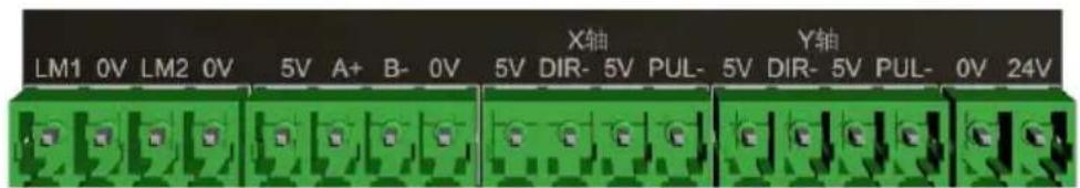
5V: PUL+ for stepper motor driver.
PUL-: PUL- of the stepper motor driver.
Power supply interface
0V: Negative power supply.
24V: Positive power supply.
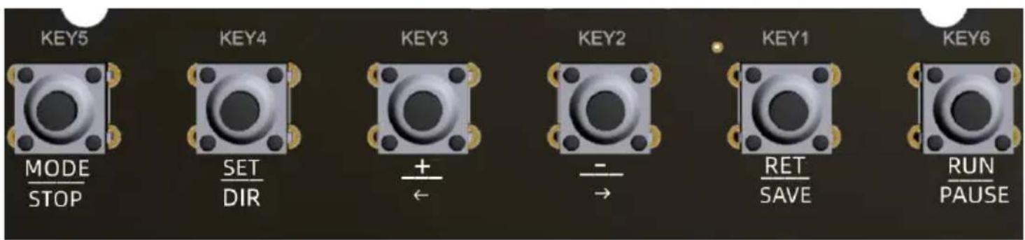
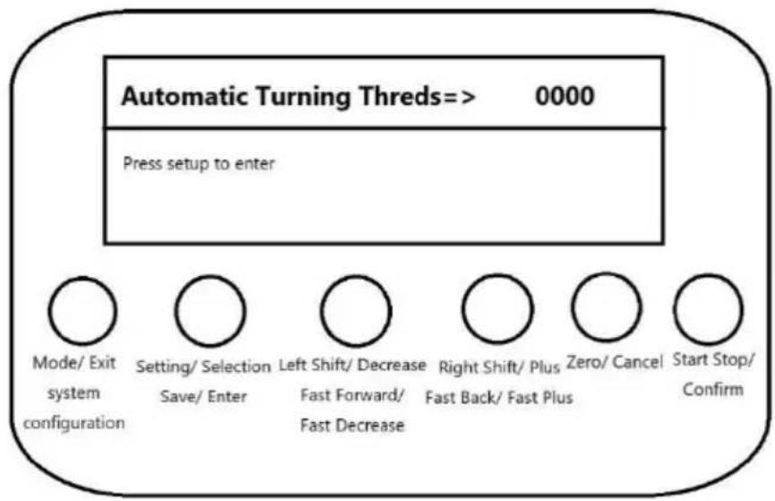
2. Key Description
There are 6 buttons, KEY1~KEY6.
KEY5:
Mode/Exit": short press action
"[System Configuration]: long press action
Under the mode selection state, short press action of the key se as the mode switching function and long press action of the key serves as the system configuration function.
Under the vehicle thread or round trip mode working state, key press to exit the current working mode and return to mode select state.
KEY4:
Setting/Selection": short press action
"[Save/Enter]: long press action
In the mode selection state, short press action of the key serves enter the setting and switch the setting parameters.
In the setting state, long press action of the key serves to save setting and enter the work.
KEY3:
"Left shift / minus": short press action
[Fast Forward / Fast Decrease]: Long press action
Left shift of the screw in manual mode, pointing or fast forward function.
Single minus or fast minus function for setup parameters in setup mode.
KEY2:
"Right shift/add": short press action
[FAST RETRACT / FAST ADD]: long press action
Right shift of the screw in manual mode, pointing or fast backward function.
Single add or fast add function for setting parameter in setting state.
KEY1:
"Clear/Cancel": short press action
Under setting state, short press key action for cancellation and e parameter setting, return to mode selection state.
Under working status, short press key action is to zero the curre position, or move the distance to zero.
KEY6:
"Start-stop/Confirm": short press action
Under the working state, start-stop action, or manual confirmation function during operation.
Functional Description
- Display area layout

The LCD screen displays a total of 4 lines of information:
The 1st line displays mode, moving direction and speed;
Lines 2 to 4 display setting parameter information, operation status, information or prompt information.
2. Tool movement function
Function Description:
Turning is carried out by synchronising the spindle speed according to the set feed length, and the direction can be switched at any time during operation.
"Mode/Exit": short press action
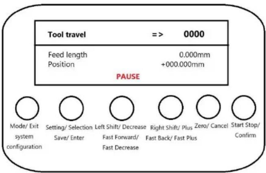
"[System Configuration]": Long press action
Short press, exit work, switch mode.
Long press, exit work, enter system configuration.
"Set/Select": Short press action
"Save/Enter": Long press action
Short press, switch direction.
Long press, invalid.
"Move Left/Subtract": short press action
"Fast Forward/Fast Decrease": Long press action
Short press, single feed length adjustment.
Long press, continuous adjustment of feed length, long press hold down, every interval of 3S will automatically feed adjustment.
"Right shift/add": short press action
[FAST RETRACT / FAST ADD]: Long press action
Short press, single feed length adjustment.
Long press, continuous adjustment of feed length, with long prehold, every interval of 3S will be adjusted automatically in position
"Zero/Cancel": Short press action
Short press, the current position is zeroed.
"Start/Stop/Confirm": short press action
Short press, run and pause control.
2. Manual Speed Shift Function
Function Description:
According to the set moving speed, move manually by 'left shift' or 'right button, and you can switch the direction under the stop state.
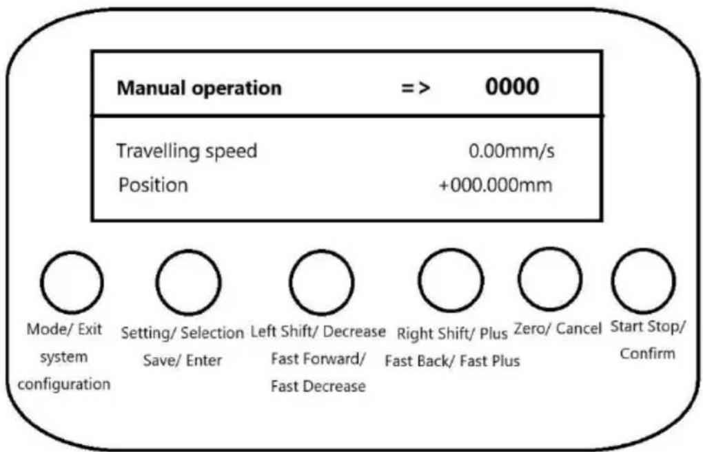
Mode/Exit": short press action
"[System Configuration]": Long press action
Short press, exit work, switch mode.
Long press, exit work, enter system configuration.
Set/Select": Short press action
"[Save/Enter]: Long press action
Short press, switch direction.
Long press, invalid.
"Move Left/Subtract": short press action
"Fast Forward/Fast Decrease": Long press action
Short press, single feed length adjustment.
Long press, continuous adjustment of feed length, long press hold down, every interval of 3S will automatically feed adjustment.
"Right shift/add": short press action
[FAST RETRACT / FAST ADD]: Long press action
Short press, single feed length adjustment.
Long press, continuous adjustment of feed length, with long press hold, e interval of 3S will be adjusted automatically in position.
Zero/Cancel": Short press action
Short press, the current position is zeroed.
"Start/Stop/Confirm": short press action
Short press, run and pause control.
- Manual distance shift function
Function Description:
According to the set distance to move, start and move the set distance the automatic stop, running process can be paused, and then start again continue to move the remaining distance.
Mode/Exit": short press action
"[System Configuration]": Long press action
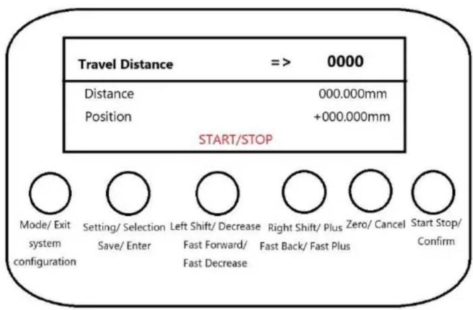
Short press, exit work, switch mode.
Long press, exit work, enter system configuration.
"Set/Select": Short press action
"[Save/Enter]: Long press action
Non-running state.
Short press to switch direction.
Long press, invalid.
"Move Left/Decrease": Short press action
[Fast Forward/Fast Decrease]: Long press action
Non-running state.
Short press, single adjustment of the travelling distance parameter.
Long press, continuous adjustment of travelling distance parameter, with long press hold, every 3S interval will be adjusted automatically.
"Right shift/add": short press action
[Fast Back/Fast Plus]: long press action
Non-running state
Short press, single adjustment of travelling distance parameter.
Long press, continuous adjustment of travelling distance parameter, with long press hold, every 3S interval will be adjusted automatica
Zero/Cancel": short press action
Under non-running state.
Short press, the 1st time first clear the distance already moved, again, clear the set distance.
"Start/Stop/Confirm": short press action
Short press, start and stop control.
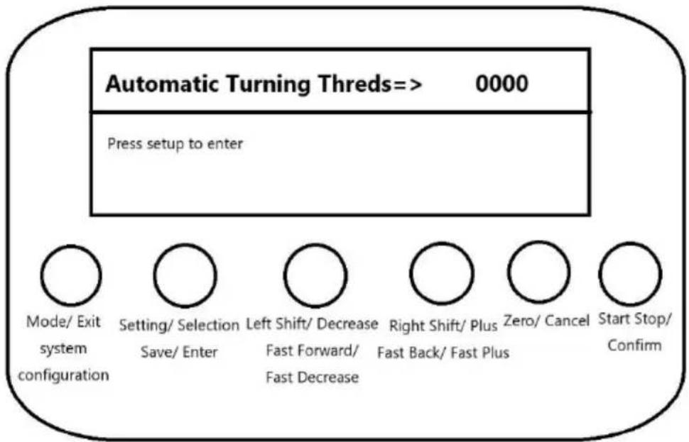
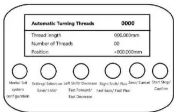
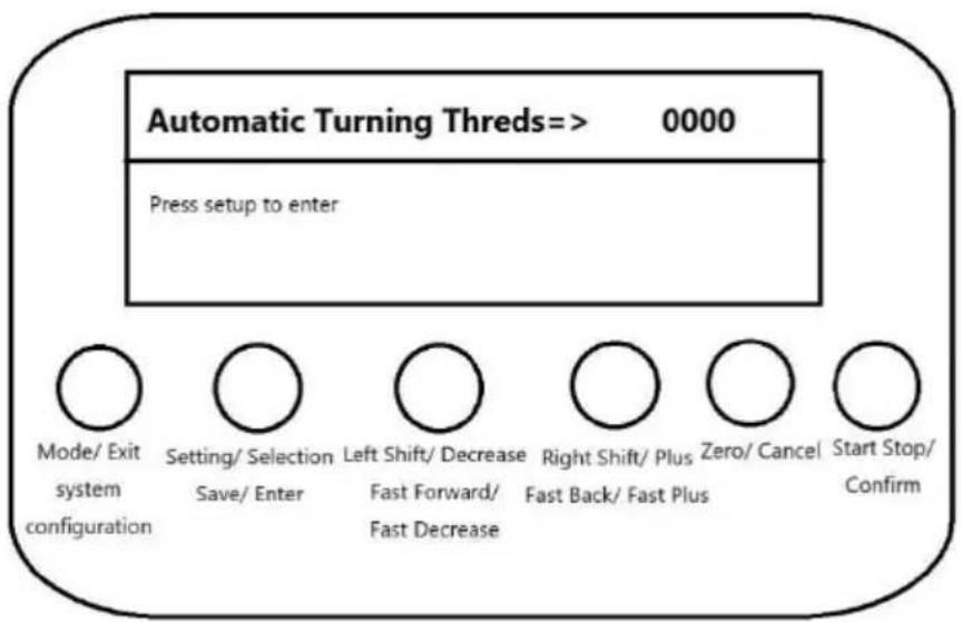
4. Automatic threading function
Function Description:
Automatic thread turning according to the set thread type, thread le and thread size.
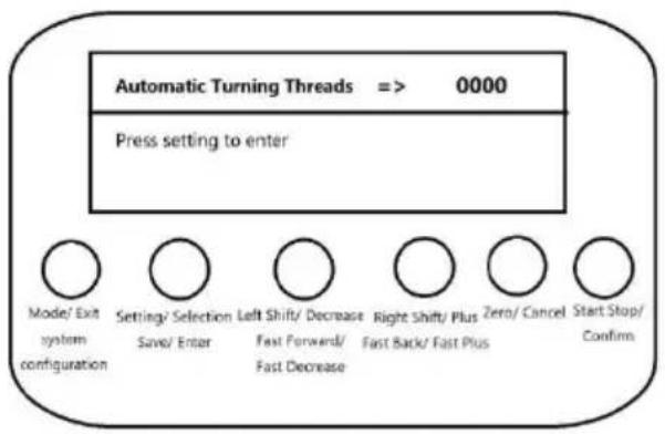
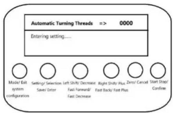
Standby status display interface Setting Up the Overdrive Interface
The standby interface shown on the left is displayed under the state of mode sele and the setting interface shown on the right is displayed after pressing the 'Setting' after entering the setting interface, the parameter setting will be cancelled after pres the 'Cancel' button, and the exit setting will be displayed, and the saving setting will be displayed when the 'Save' button is pressed. When press 'Save' button, it will display save setting, and then it will ent working state automatically.
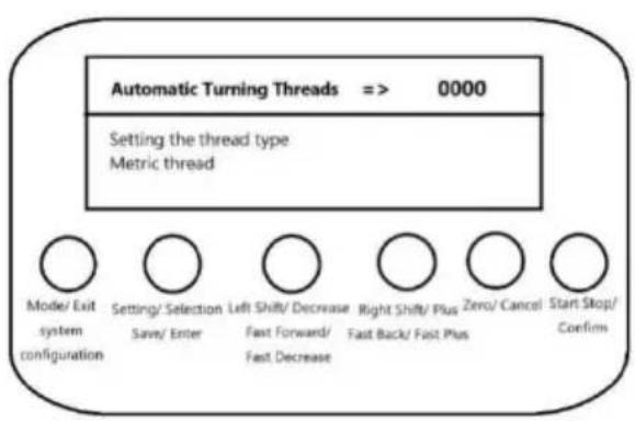
Setting parameter interface Prompt to enter working operation
In the setting state
Short press the 'Set/Select' button to switch the setting parameters.
Parameter list:
Setting thread type: metric thread, inch thread and non-standard precision thread.
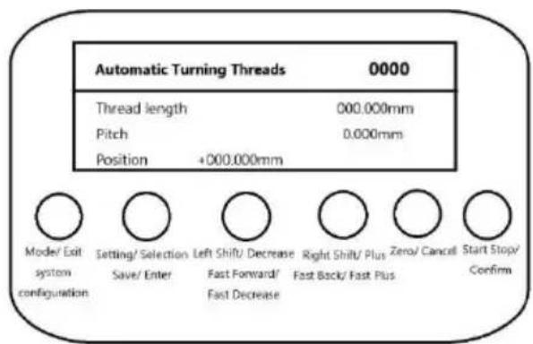
Setting thread size: set the pitch size for metric threads and non-standard precision threads, and set the number of teeth per inch for inch threads.
Set thread length: xxx.xxxmm.
Start turning mode: manual key operation, immediate automatic operation and delayed automatic operation.
Start back mode: manual key operation, immediate automatic operation and delayed automatic operation.
Delay time of automatic operation: 1~30 seconds.
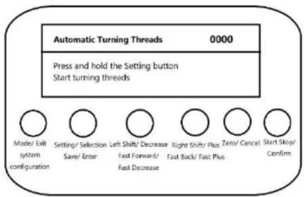
Long press 'Save/Enter' button to save the parameters and enter the working state automatically. If the thread length is 0, it will prompt the message that the thread not set.
Short press 'Clear/Cancel' button to cancel parameter setting and return to mode selection interface.
Metric/non-standard precision thread interface Fractional Thread Interface
When Metric or Non-Standard Precision Threads is selected the left graph screen is displayed with pitch information on line 3.
When imperial threads are selected, the right graph screen is displayed with the nu of teeth per inch in line 3.
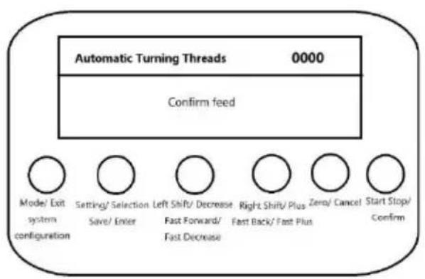
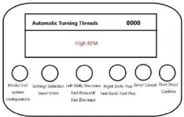
Confirmation of tool feed/return prompt interface High RPM Alert Screen
When the start turning mode and start back mode are set to manual key operation interface on the left will be prompted when starting tool feed and retract, and it is necessary to press the 'Confirm' button briefly to run.
If the speed of the synchronous spindle of stepping motor is too high, it will prompt interface of too high speed on the right, and it is necessary to reduce the spindle. Under the working condition, press the 'Mode/Exit' button briefly to stop the current and return to the mode selection interface automatically.
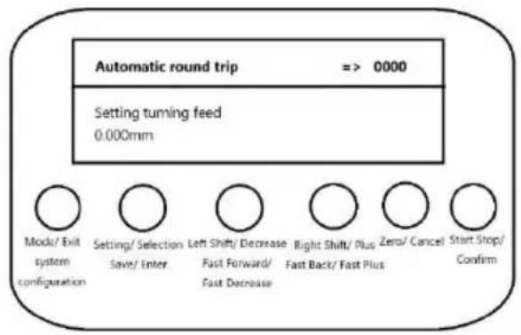
5.Automatic round trip function
Function Description:
Synchronised spindle movement according to the set turning length and feed length, automatic return after moving the set turning length.
Standby status display interface Setting Up the Overdrive Interface

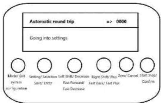
The standby interface shown on the left is displayed under the state of mode sele and the setting interface shown on the right is displayed after pressing the 'Setting' after entering the setting interface, the parameter setting will be cancelled after pres the 'Cancel' button, and the exit setting will be displayed, and the saving setting w displayed when the 'Save' button is pressed. When press 'Save' button, it will disl save setting, and then it will enter working state automatically.
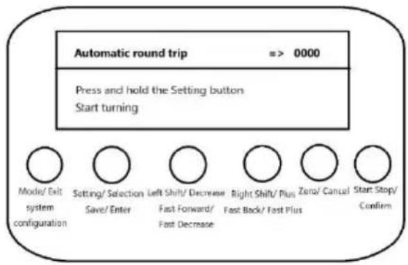
Setting parameter interface Prompt to enter working operation
Under the setting state.
Short press 'Set/Select' button to switch the setting parameters.
Press and hold the 'Save/Enter' button to save the parameters and enter the work state automatically.
Short press 'Clear/Cancel' button to cancel parameter setting and return to mode selection interface.
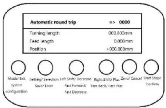
Running state interface Pause state interface
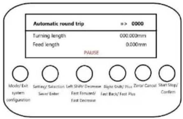
In this pause state, line 4 displays the pause, and in the running state, line 4 disposition information.
In pause state, press 'Set/Select' button briefly to switch the direction.
Press 'Set/Select' button briefly to switch the direction.
Press 'Zero/Cancel' button briefly to zero the position.
In pause or running state, press 'Start/Stop/Cancel' button briefly to switch direction.
Press 'Start/Stop/Confirm' button briefly to start or pause the function.
Short or long press 'Left shift/decrease' or 'Right shift/add' button to adjust the feed length.
Short press 'Mode/Exit' button to stop the current work and automatically exit back mode selection interface.
6.System Configuration Functions
Function Description:
Set system parameters, including display language, buzzer switch.
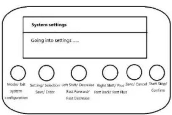
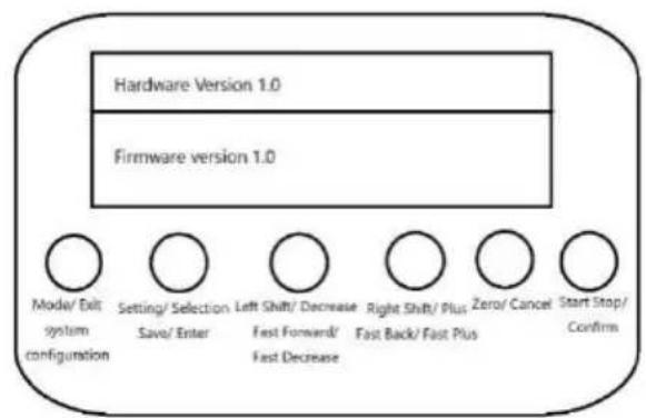
Entering the Settings screen Version Information Screen
Under the mode selection status, long press 'System Configuration' button to enter the system setting interface, displaying the interface on the left
After entering the setting interface, press the 'Cancel' button to cancel the parameter setting and display the exit setting, long press the 'Save' button to display the sav setting, and then return to the mode selection interface automatically.
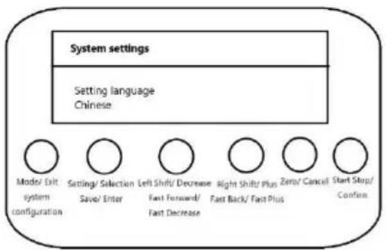
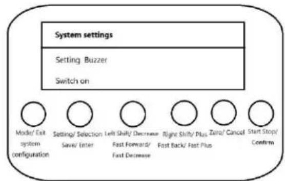
Language Settings screen Buzzer Setting Interface
Short press 'Set/Select' button to switch the setting parameters.
Press and hold 'Save/Enter' button to save parameters and return to mode selection interface.
Press 'Clear/Cancel' button briefly to cancel parameter setting and return to mode selection interface.
Parameter:
Setting language: Chinese, English and Russian.
Setting buzzer: on and off.
Encoder and stepper motor parameters
Stepping motor configuration requirements: stepping motor a circle of 1600 pulses, a circle to move 2mm.
Encoder requirements: 1000 pulses / circle, spindle and encoder gear ratio of 2:1, the spindle rotates 1 circle, the encoder rotates 2 circles.
Lathe Adjustments

- Chuck Replacement: Turn the lathe off and unplug it from its power source. Place the tailstock as far away from the chuck as possible and place a piece of wood or a cloth underneath chuck to protect the machine. Remove the three bolts holding the chuck in place by remove their nuts and subsequently remove the chuck. Tapping the chuck with a soft mallet might required. To place a new chuck onto the spindle, follow the above steps in reverse order
- Jaw Replacement: Place the chuck key into the chuck hole and rotate anti-clockwise until the jaws are at their maximum open distance. The jaws can now be manually pulled out. To new jaws into the chuck, choose the # 1 jaw and place it into the desired chuck slot. E the top groove of that slot is not visible when inserting the jaw. Once the jaw is seated rotate the chuck clockwise to drag down and secure the jaw. Repeat this with jaws #2 a
- Tailstock Adjustment: To adjust the placement of the tailstock rest, loosen the nut on its base, change its position, and retighten the nut. Offset the tailstock in order to cut bevels or ta
- Tailstock Locking: Turn the clamping lever clockwise to lock the tailstock in place, or anti-clockwise to unlock.
- Tool Post Adjustment: To adjust the tool post, simply loosen both bolts holding it in place, move it to the desired position, and retighten the bolts. Loosen the bolts on top of the tool po replace work cutters.
- Carriage Adjustment: Rotate the carriage handwheel clockwise to move the carriage towards the tailstock. Rotate the handwheel anti-clockwise to move the carriage towards the chuck.
- Carriage Locking: Turn the toolpost control handle clockwise to tighen and anti-clockwise to loosen. This handle must be loosened before automatic feeds are used.
- Cross Slide Adjustment: Turning the cross slide handwheel will slide the tool post perpendicular to the ways. Turn the handwheel clockwise to move it back, and anti-clockwise move forward.
- Carriage Feed Control: Move the half nut lever down to engage the half nut and move the carriage under power. Make sure to disengage the half nut before making any adjustments
avoid unexpected carriage movement.
- Compound Control: Turn the compound control wheel anti-clockwise to move the compound outwards and clockwise to move it inwards, changing the cutting angle.
Quill Locking: Rotate the lever clockwise to lock the spindle and anti-clockwise to unlock. - Tail Feed Adjustment: Rotate the tail feed handwheel clockwise to advance the tailstock towards the chuck. Rotate the handwheel anti-clockwise to move the tailstock away from the chuck.
Operation
- Workpiece Holding and Drilling: Use the chuck to hold a workpiece firmly in place. Use the tailstock to press a drill into the rotating workpiece.
- Face Cutting: Use the chuck to hold a workpiece firmly in place. Use the tool post to press cutter into the face of the workpiece. The edge of the cutter must be the same height as centre.
- Internal Cutting: Use the chuck to hold a workpiece firmly in place. Rotate the tool post such that the cutter is placed in the middle of the front face of the workpiece.
- Bevel Cutting: Use the chuck to hold a workpiece firmly in place. Adjust the angle of the tool post to cut bevels into the workpiece.
- Thread Cutting: To cut threads, use the chuck to hold a workpiece firmly in place and engage the half nut. Use the tool post to press a cutter into the face of the workpiece.
Wiring Diagram
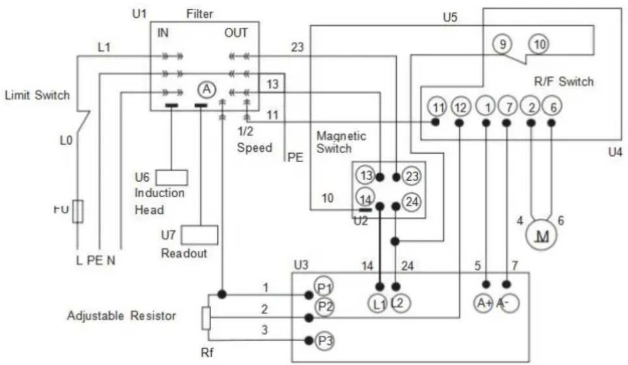
Key
| A | Ammeter | PE | Ground Line |
| M | Motor | U | Integrated Circuit |
| L | Load Wire | P | Connector |
| N | Neutral Wire | FU | Fuse |
Maintenance
- Clean the machine of any debris after every use.
- Lubricate the moving parts of the device with NLGI 2 grease between uses.
DO NOT let excessive debris accumulate on the tray. Clear debris as it arises, stopping the lathe if necessary.
Periodically inspect moving parts for signs of wear and tear. Repair or replace any damaged or worn parts before further use. - Periodically inspect bolts, screws, levers, and other fasteners for any looseness. Tighten as needed.
Troubleshooting
| Potential Problems | Common Solutions |
| The workpiece's surface is rough. | Re-sharpen the cutting tool. |
| Reduce the feed rate. | |
| Clamp the cutting tool with less overhang. | |
| Increase the tool tip's radius. | |
| The cutting tool has a sho lifespan. | Reduce the cutting speed. |
| Lower the crossfeed distance. | |
| Add more lubricant onto the workpiece. | |
| The cutting edge breaks off | Increase the wedge angle. |
| Lubricate the workpiece uniformly. | |
| Tighten the spindle bearing. | |
| The cutting thread is wrong | Adjust the cutting tool's grinding angle. |
| Adjust the cutting tool's pitch. | |
| Adjust the workpiece's diameter. | |
| The workpiece becomes conned. | Adjust the tailstock to the centre of the workpiece. |
| Align the top slide properly. | |
| The lathe is chattering. | Reduce the feed rate. |
| Tighten the main bearing. | |
| Flank wear is too high. | Increase the clearance angle. |
| Properly centre the cutting tool onto the workpiece. | |
| The centre runs hot. | Loosen the tailstock. |
| The spindle does not active | Unlock the emergency stop switch. |
Controller fault indication and handling
| NO. | Error code | Cause failure | Fault handling |
| 1 | ER01 | Over-current protection | Check whether the motor interface is go eplace the control box. |
| 2 | ER02 | HALL signal failure | Check whether the motor interface is go ition, or replace the motor or controller. |
| 3 | ER03 | Locked-rotor protection | Check whether the motor interface is go hether the motor load is excessive. |
| 4 | ER04 | Chip failure | Replace the motor and control box |
| 5 | ER05 | Motor failure | Check whether the motor interface is go hether the motor load is excessive. |
| 6 | ER06 | Potentiometer failure | Check the speed control interface is in dition. |
| 7 | No display, the switch lights come on | 1 Main board is broken. 2 The display and the main board connection line con ad. |
Manufacturer: Shanghaiuxinmuyeyouxianggsi
Address: Shuangchenglu 803nong11hao1602A-1609shi, baoshanqu, shanghai 200000 CN.
Imported to USA: Sanven Technology Ltd., Suite 250, 9166 Anaheim Pla Rancho Cucamonga, CA 91730

E-CrossStu GmbH
Mainzer Landstr.69, 60329 Frankfurt am Ma

YH CONSULTING LIMITED.
C/O YH Consulting Limited Office 147, Centurion H, London Road, Staines-upon-Thames, Surrey, TW18 4
VEVOR
TOUGH TOOLS, HALF PRICE
Technical Support and E-Warranty Certificate www.vevor.com/support
VEVOR®
TOUGH TOOLS, HALF PRICE
NEED HELP? CONTACT US!
Have product questions? Need technical support? Please feel fr contact us:
Technical Support and E-Warranty Certificate www.vevor.com/support
This is the original instruction, please read all manual instruction carefully before operating. VEVOR reserves a clear interpretation user manual. The appearance of the product shall be subject to product you received. Please forgive us that we won't inform you there are any technology or software updates on our product.
Functional Description
Set/Select " : action de pression courte
' Set/Select " : action de pression courte
| A | Ammeter | PE | Ground Line |
| M | Motor | U | Integrated Circuit |
| L | Load Wire | P | Connector |
| N | Neutral Wire | FU | Fuse |
Maintenance
Place, Rancho Cucamonga, CA 91730

E-CrossStu GmbH
Mainzer Landstr.69, 60329 Frankfurt am Ma

YH CONSULTING LIMITED.
C/O YH Consulting Limited Office 147, Centurion H
London Road, Staines-upon-Thames, Surrey, TW18 4
VEVOR
TOUGH TOOLS, HALF PRICE
Assistance technique et certificate de garantie electronique www.vevor.com/support
VEVOR®
TOUGH TOOLS, HALF PRICE
NEED HELP? CONTACT US!
Have product questions? Need technical support? Please feel fr contact us:
Technical Support and E-Warranty Certificate www.vevor.com/support
This is the original instruction, please read all manual instruction carefully before operating. VEVOR reserves a clear interpretation user manual. The appearance of the product shall be subject to product you received. Please forgive us that we won't inform you there are any technology or software updates on our product.
Functional Description
| A | Ammeter | PE | Ground Line |
| M | Motor | U | Integrated Circuit |
| L | Load Wire | P | Connector |
| N | Neutral Wire | FU | Fuse |
Maintenance
Place, Rancho Cucamonga, CA 91730

E-CrossStu GmbH
Mainzer Landstr.69, 60329 Frankfurt am Ma

YH CONSULTING LIMITED.
C/O YH Consulting Limited Office 147, Centurion H
London Road, Staines-upon-Thames, Surrey, TW18 4
VEVOR®
TOUGH TOOLS, HALF PRICE
NEED HELP? CONTACT US!
Have product questions? Need technical support? Please feel fr contact us:
Technical Support and E-Warranty Certificate www.vevor.com/support
This is the original instruction, please read all manual instruction carefully before operating. VEVOR reserves a clear interpretation user manual. The appearance of the product shall be subject to product you received. Please forgive us that we won't inform you there are any technology or software updates on our product.
Functional Description
| A | Ammeter | PE | Ground Line |
| M | Motor | U | Integrated Circuit |
| L | Load Wire | P | Connector |
| N | Neutral Wire | FU | Fuse |
Maintenance
C/O YH Consulting Limited Office 147, Centurion H, London Road, Staines-upon-Thames, Surrey, TW18 4
VEVOR
TOUGH TOOLS, HALF PRICE
Soporte的技术ico y certificate de garantia electrònica www.vevor.com/support
VEVOR®
TOUGH TOOLS, HALF PRICE
NEED HELP? CONTACT US!
Have product questions? Need technical support? Please feel fr contact us:
Technical Support and E-Warranty Certificate www.vevor.com/support
This is the original instruction, please read all manual instruction carefully before operating. VEVOR reserves a clear interpretation user manual. The appearance of the product shall be subject to product you received. Please forgive us that we won't inform you there are any technology or software updates on our product.
Functional Description
11. Ukstad obszaru $wyietlania
| A | Ammeter | PE | Ground Line |
| M | Motor | U | Integrated Circuit |
| L | Load Wire | P | Connector |
| N | Neutral Wire | FU | Fuse |
Maintenance
C/O YH Consulting Limited Office 147, Centurion H
London Road, Staines-upon-Thames, Surrey, TW18 4
VEVOR®
TOUGH TOOLS, HALF PRICE
NEED HELP? CONTACT US!
Have product questions? Need technical support? Please feel fr contact us:
Technical Support and E-Warranty Certificate www.vevor.com/support
This is the original instruction, please read all manual instruction carefully before operating. VEVOR reserves a clear interpretation user manual. The appearance of the product shall be subject to product you received. Please forgive us that we won't inform you there are any technology or software updates on our product.
Functional Description
13. Weergavegebied lay-out
| A | Ammeter | PE | Ground Line |
| M | Motor | U | Integrated Circuit |
| L | Load Wire | P | Connector |
| N | Neutral Wire | FU | Fuse |
Maintenance
C/O YH Consulting Limited Office 147, Centurion H, London Road, Staines-upon-Thames, Surrey, TW18 4
VEVOR
TOUGH TOOLS, HALF PRICE
Technische ondersteuning en e-garantiecertificaat www.vevor.com/support
VEVOR
TOUGH TOOLS, HALF PRICE
NEED HELP? CONTACT US!
Have product questions? Need technical support? Please feel fr contact us:
Technical Support and E-Warranty Certificate www.vevor.com/support
This is the original instruction, please read all manual instruction carefully before operating. VEVOR reserves a clear interpretation user manual. The appearance of the product shall be subject to product you received. Please forgive us that we won't inform you there are any technology or software updates on our product.
Functional Description
| A | Ammeter | PE | Ground Line |
| M | Motor | U | Integrated Circuit |
| L | Load Wire | P | Connector |
| N | Neutral Wire | FU | Fuse |
Maintenance
C/O YH Consulting Limited Office 147, Centurion H, London Road, Staines-upon-Thames, Surrey, TW18 4
VEVOR
TOUGH TOOLS, HALF PRICE