WM210V - Metal Lathe Vevor - Free user manual and instructions
Find the device manual for free WM210V Vevor in PDF.

| Product type | Metal lathe |
| Brand and model | Vevor WM210V |
| Swing over bed capacity | 210 mm |
| Swing over cross slide | 110 mm |
| Distance between centers | 370 mm |
| Bed width | 100 mm |
| Spindle bore | 21 mm |
| Spindle taper | MT3 |
| Number of spindle speeds | Variable (50-2500 RPM) |
| Metric threads | 14 pitches (0.3-3 mm) |
| Imperial threads | 10 pitches (10-44 TPI) |
| Longitudinal feed | 0.089-0.198 mm/rev |
| Compound slide travel | 80 mm |
| Cross slide travel | 85 mm |
| Longitudinal slide travel | 370 mm |
| Tailstock quill travel | 50 mm |
| Tailstock taper | MT2 |
| Main motor | 550 W, 110 V~60 Hz / 220 V~50 Hz |
| Net weight | 60.6 kg |
| Gross weight | 78.4 kg |
| Package dimensions | 905 × 455 × 540 mm |
| Warranty | 1 year |
| Standard accessories | 3-jaw chuck, tool box with centers, wrenches, pulleys |
| Maintenance and lubrication | Daily lubrication of ways and lead screw with 20W oil |
Frequently Asked Questions - WM210V Vevor
User questions about WM210V Vevor
0 question about this device. Answer the ones you know or ask your own.
Ask a new question about this device
Download the instructions for your Metal Lathe in PDF format for free! Find your manual WM210V - Vevor and take your electronic device back in hand. On this page are published all the documents necessary for the use of your device. WM210V by Vevor.
USER MANUAL WM210V Vevor
Technical Support and E-Warranty Certificate
www.vevor.com/support
METAL LATHE USER MANUAL
MODEL:WM210V
We continue to be committed to provide you tools with competitive price. "Save Half", "Half Price" or any other similar expressions used by us only represents an estimate of savings you might benefit from buying certain tools with us compared to the major top brands and does not necessarily mean to co all categories of tools offered by us. You are kindly reminded to verify carefully when you are placing an order with us if you are actually Saving Half in comparison with the top major brands.
MODEL:WM210V
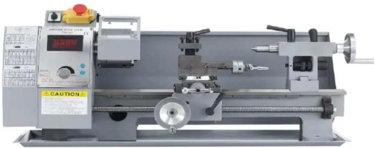
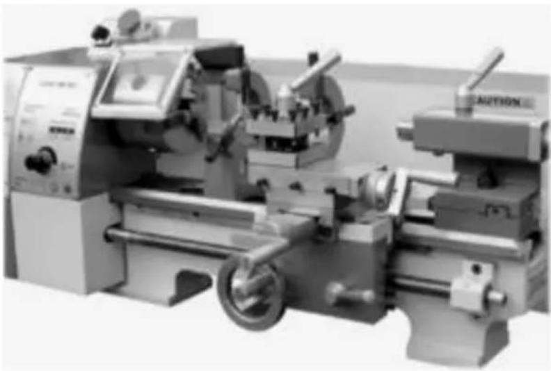
natural_image
Industrial lathe machine with control panel and warning label (no readable text or symbols on the machine itself)(The picture is for reference only, please refer to the actual obje
NEED HELP? CONTACT US!
Have product questions? Need technical support? Please feel fr contact us:
Technical Support and E-Warranty Certificate www.vevor.com/support
This is the original instruction, please read all manual instruction carefully before operating. VEVOR reserves a clear interpretation user manual. The appearance of the product shall be subject to product you received. Please forgive us that we won't inform you there are any technology or software updates on our product.
 | Warning-To reduce the risk of injury, user must read instructio manual carefully. |
 | This product is subject to the provision of European Directive 2012/19/EC. The symbol showing a wheelie bin crossed through indicates that the product requires separate refuse collection in European Union. This applies to the product and all accessori marked with this symbol. Products marked as such may not discarded with normal domestic waste, but must be taken to collection point for recycling electrical and electronic devices |
MATTERS NEEDING ATTENTION
The information contained in this handbook is intended as a guide to the operation of these machines and does not form part of any contract. The data it contains been obtained from the machine manufacturer and from other sources. Whilst every effort has been made to ensure the accuracy of these transcriptions it is to be impracticable to verify each and every item. Furthermore, development of the machine may mean that the equipment supplied may differ in detail from the descriptions herein. The responsibility therefore lies with the user to satisfy him that the equipment or process described is suitable for the purpose intended.
QUALITY ASSURANCE
We will make every effort to ensure the quality of our products, and we pro consumers that we will guarantee our products for one year, except for mach damage caused by improper operation of customers, and accidents resulting therefrom, or abnormal wear and damage caused by lack of maintenance.
Our company reserves the right to make changes to this specification and pr specifications. We will make continuous efforts to improve the quality of our products.
All rights reserved. Reproduction or reproduction is not allowed without permission.
SAFETY WARNING
| Symbol | Symbol Description |
 | Warning - To reduce the risk of injury, user must read inst manual carefully. |
 | This symbol, placed before a safety comment, indicates a ki precaution, warning, or danger. Ignoring this warning may lea accident. To reduce the risk of injury, fire, or electrocution, always follow the recommendation shown below. |
 | Danger!Risk of personal injury or environmental damage! Risk of ele shock! Risk of personal injury by electric shock! |
| ~ | Direct current |
 | Beware of clamping |
 | Warning- Be sure to wear ear protectors when using this p |
 | Warning- Be sure to wear eye protectors when using this p |
 | Do not put hands into safety guard when machine is workir |
 | No entry automatic machinery in operation Autherized person only |
 | Do not fill oil during operation |
 | Do not turn during repair |
 | No fatigue operation |
 | The operation is no phone calls |

WARNING: Read all safety warnings, instructions, illustrations and
specifications provided with this machine. Failure to follow all instructions listed below may result in electric shock, fire and/or serious injury.
Save all warnings and instructions for future reference.
- The machine tool should be used by experienced personnel. If you are not familiar with the operation process of the lathe, do not use the machine to will Use the instructions before operating.
- Before starting the machine tool, the safety cover should be in the correct position.
- Before starting the machine tool, please check whether the tool rest wrench chuck key are removed.
- Prevent the machine from starting accidentally. Turn off the motor power be clamping the workpiece or tool.
- Don't force cut. Cutting according to the set cutting speed, cutting depth and feed speed.
- Use the right tools. Use the correct tool or workpiece for machining.
- Keep the tool sharp and clean to ensure normal and safe operation. Lubric and replace accessories regularly.
- Before adjusting or repairing the machine, be sure to disconnect the power supply.
-
Please check the safety performance of the machine before starting it. Check the performance of all moving parts. All parts must be installed correctly. Damaged parts must be repaired promptly.
-
When the machine is running, the operator shall not leave.
- Keep the working place clean, dirty working environment is easy to lead accidents.
- Do not use the machine in dangerous environment.
Do not work in damp places. Ensure that electrical components are prot from moisture. Keep good lighting.
- Children are prohibited from entering the work site, and non-operating personnel should keep a safe distance from the work area.
- To keep children out of the work area. The door should be locked when the workshop.
- Dress appropriately. Don't wear loose clothing, gloves, ties, rings, bracelets, jewelry, etc. To be on the safe side, build discuss wearing non-slip shoe you have long hair, please wear a work hat.
- Wear protective glasses when operating.
- Pay attention to where you stand and keep your balance at all times.
- Do not place your hands near the moving parts of the machine.
- Do not perform any setting operations while the machine is running.
- Read and understand all warning signs posted on the machine.
- This manual is intended only to familiarize customers with the operation of machine and is not a training manual.
- Please obey these warnings or serious injury may result.
- The machine will produce some harmful chemicals in the work of dust, s grinding and drilling produced by grinding. To reduce the harm of these chemicals, please work in a well-ventilated place and wear safety devices. Such as particulate filter masks.
TECHNICAL PARAMETER
| Type number | WM210V |
| Capacities | |
| Swing over Bed | 210mm |
| Swing over Cross Slide | 110mm |
| Distance Between Centers | 370mm |
| Width of Bed | 100mm |
| Headstock | |
| Hole Through Spindle | 21mm |
| Taper in Spindle Nose | MT3 |
| Number of Spindle Speeds | Variable |
| Range of Spindle Speeds | 50-2500RPM |
| Feeding and Threading | |
| Number of Metric Threads | 14 |
| Range of Metric Threads | 0.3~3mm |
| Number of 1mperial Threads | 10 |
| Range of 1mperial Threads | 10~44T.P.I. |
| Range of Longitudinal Feed | 0.089-0.198mm |
| Compound and Carriage | |
| Tool Post Type | 4 |
| Maximum Compound Slide Travel | 80mm |
| Maximum Cross Slide Travel | 85mm |
| Maximum Carriage Travel | 370mm |
| Tailstock | |
| Tailstock Spindle Travel | 50mm |
| Taper in Tailstock Spindle | MT2 |
| Miscellaneous | |
| Main Motor | 110V~60Hz/220V~50Hz,550W, |
| Product Weight | N.W:60.6Kg; G.W:78.4Kg |
| Package Size | 905*455*540 mm |
The general information given in this specification is not binding.
Standard accessories
- Oil pan 1
- Rear chip plate 1
- Three jaw chuck 1
- specification 1
- Detection table 1
- Tool box 1
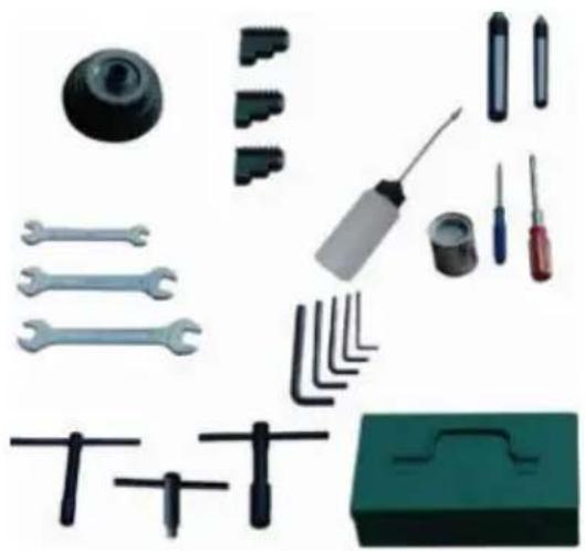
natural_image
Collection of mechanical tools and components including wrenches, screwdrivers, and a green base case (no text or symbols visible)Fig. 1
Accessories in the tool box (Fig. 1)
1 Dead Center MT3
1 Dead Center MT2
3 Tool post wrench
1 Oil Gun
1 Cross screwdriver
1 Flat screwdriver
1 Key for 3-Jaw Chuck
5 Hex socket wrenches
3 Double End Head wrenches
9 Pulley set (24T,33T,35T,40T,50T,52T,60T,66T,72T)
Special accessories (Accessories that require additional payment)
Four jaw chuck and back plate (connecting plate)
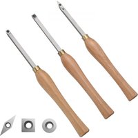
Turning tool
Drill chuck and connecting rod
Heel rest
Center frame
Back disk
Disjointed disk
Tool rest protection cover
Lead screw protective cover
UNCRATING AND CLEAN.UP
- Finish removing the wooden crate from around the lathe
- Check all the accessories of the machine tool according to the pa list.
- Unbolt the lathe from the shipping crate bottom.
- Choose a location for the lathe that is dray, has good lighting an enough room to be able to service the lathe on all four sides.
- With adequate lifting equipment, slowly raise the lathe off the ship or crate bottom. Do not lift by spindle. Make sure lathe is balanced by moving to sturdy bench or stand.
- To avoid twisting the bed, the lathe's location must be absolutely level. Bolt the lathe to the stand (if used). If using a bench, through for best performance.
- Clean all rust protected surfaces using a mild commercial solvent, kerosene or diesel fuel. Do not use paint thinner, gasoline or lacqu thinner. These will damage painted surfaces. Cover all cleaned surf with a light film of 20W machine oil.
- Remove the end gear cover. Clean all components of the end gear assembly and coat all gears with a heavy, non-slinging grease.
FOUNDATION DRAWING
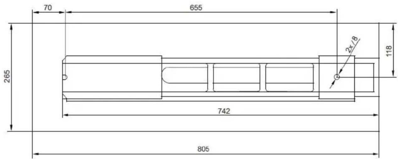
text_image
70 655 265 742 805 118 2x/8Fig. 2
Lathe Bed (Fig. 3)
The lathe bed is made of high-grade iron. By combining high cheeks strong cross ribs, a bed of low vibration and rigidity is produced. It integrates the headstock and drive unit, for attaching the carriage and leadscrew. The two precision-ground V - sideways, re-enforced by hea hardening and grinding, are the accurate guide for the carriage and tailstock. The main motor is mounted to the rear of the leftside of th
natural_image
Industrial machine with metallic components and a circular head (no visible text or symbols)Fig. 3
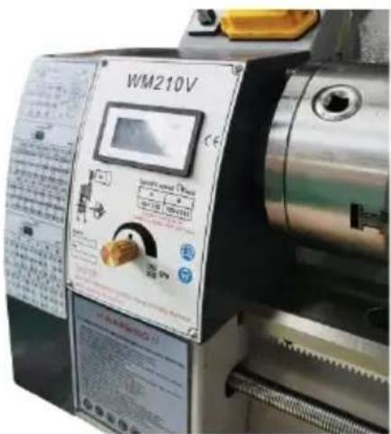
Headstock (Fig. 4)
The headstock is cast from high grade, low vibration cast iron. It is both the bed with four screws. The headstock houses the main spindle with precision taper roller bearings and the drive unit.
The main spindle transmits the torque during the turning process.1t al holds the workpieces and clamping devices. (e.g.3-jawchuck).
text_image
WM210V Control panel W-100 W-150 W-200 W-250 W-300 W-350 W-400 W-450 W-500 W-550 W-600 W-650 W-700 W-750 W-800 W-850 W-900 W-950 W-1000Fig. 4
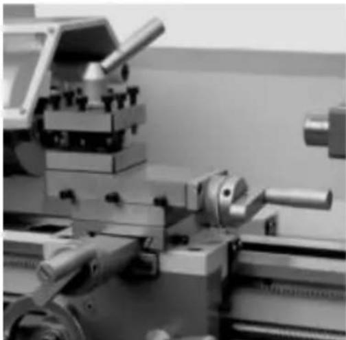
Carriage (Fig. 5)
The carriage is made from high quality cast iron. The slide parts are smoothly ground. They fit the V on the bed without play. The lower s parts can be easily and simply adjusted. The cross slide is mounted c carriage and moves on a dove tailed slide. Play in the cross slide ma adjusted with the gibs.
Move the cross slide with its conveniently positioned handwheel.
There is a graduated collar on the handwheel.
A four way tool post is fitted on the top slide and allows four tools clamped. Loosen the center clamp handle to rotate any of the four too position.
natural_image
Close-up of a mechanical lathe machine with no visible text or symbolsFig. 5
Apron (Fig. 6)
The apron is mounted on the bed. It houses the half nut with an e lever for activating the automatic feed. The half nut gibs can be adj from the outside.
A rack, mounted on the bed, and a pinion operated by handwheel o carriage allow for quick travel of the apron.
natural_image
Close-up of a mechanical lathe machine with a metallic wheel and circular components, showing no visible text or symbols.Fig. 6
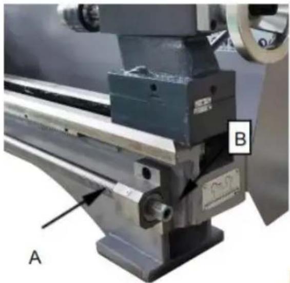
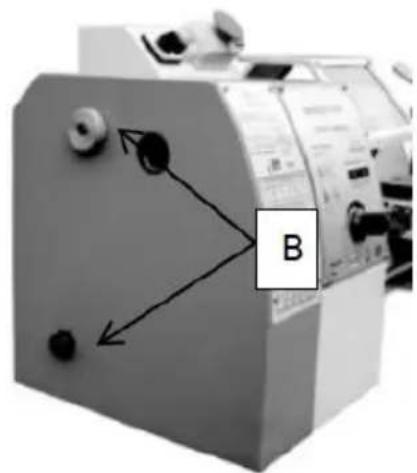
Leadscrew
The lead screw (A, Fig.7) is mounted on the front of the machine b connected to the gear box at the left for automatic feed and is supp bearing on both ends. The hex nut(B, Fig.7)on the right end is design take up play on the lead screw.
natural_image
Close-up of a mechanical tool with labeled components A and B, no readable text or symbols beyond labelsFig.7
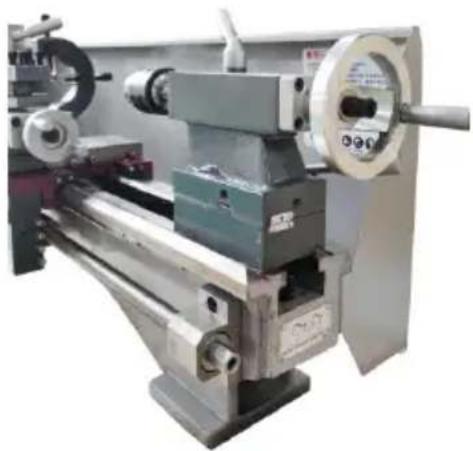
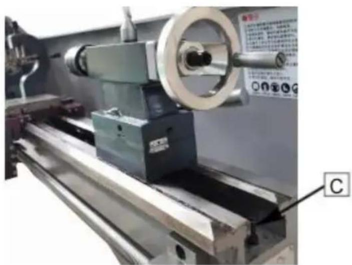
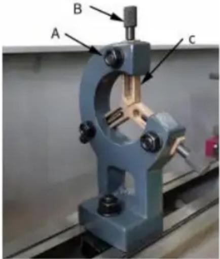
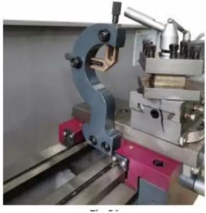
Tailstock (Fig. 8)
The tailstock slides on a V way and can be clamped at any location. tailstock has a heavy-duty spindle with a Morse taper No. 2 socket a graduated scale. The spindle can be clamped at any location with a clamping lever. The spindle is moved with a handwheel at the end of tailstock.
natural_image
Industrial machine with a large cylindrical component and a labeled section (C), no visible text or symbols on the machinery itself.Fig.8
Notice:
Fit the securing screw (C, Fig. 8) at the end of the lathe in order the tailstock from falling off the lathe bed.
Operating equipment
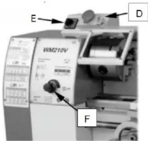
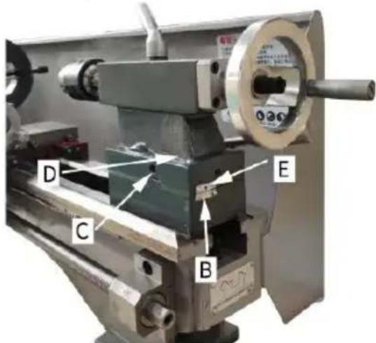
1. Emergency :Button 0N.0FF Switch (D,Fig. 9)
The machine is switched on and off with ON/OFF button. Depress to all machine functions. To restart, lift the cover and press ON button.
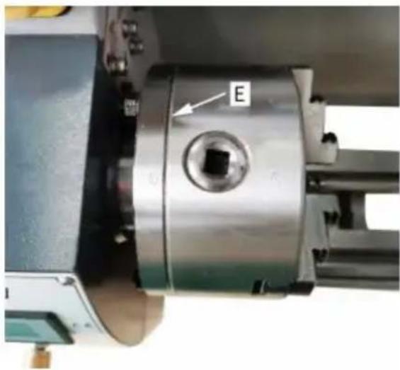
2. Change-over Switch(E, Fig. 9)
After the machine is switched on, turn the switch to "F" position for counter-clockwise spindle rotation(forward). Turn the switch to"R" position for clockwise spindle rotation(reverse) ."0"position is OFF and spindle remains idle.
3. Variable Speed Control Switch (F, Fig. 9)
Turn the switch clock wise to increase the spindle speed. Turn the s counter-clockwise to decrease the spindle speed. The possible speed range is dependent from the position of the drive belt.
text_image
E D WM210V F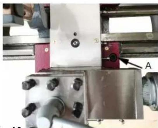
natural_image
Close-up of a mechanical assembly with metallic components and a labeled component 'A' (no readable text or symbols beyond label)Fig.9 Fig.10
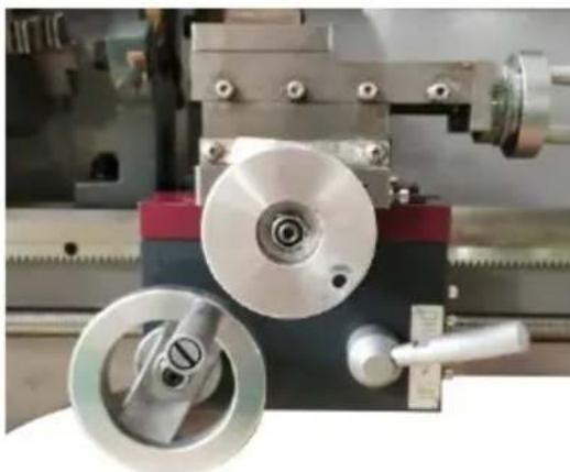
4. Carriage Lock
Turn hex socket cap screw (A, Fig. 10) clockwise and tighten to lock counter-clockwise and loosen to unlock.
Caution: carriage lock screw must be unlocked before engaging autom feeds or damage to lathe may occur.
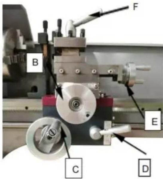
5. Longitudinal Traverse Handwheel (B, Fig.11)
Rotate hand wheel clockwise to move the apron assembly toward the tailstock (right). Rotate the hand wheel counter-clockwise to move the apron assembly to ward the headstock(left).
6. Cross Traverse Lever (C, Fig. 11)
Clock wise rotation moves the cross slide toward the rear of the ma
7. Half Nut Engage Lever (D, Fig. 11)
Move the lever down to engage. Move the lever up to disengage.
8. Compound Rest Traverse Lever (E, Fig. 11)
Rotate clockwise or counter-clockwise to move or position.
9 . Tool Post Clamping Lever (F,Fig. 11)
Rotate counter-clockwise to loosen and clockwise to tighten. Rotate the tool post when the lever is unlocked.
text_image
B F E C DFig.11
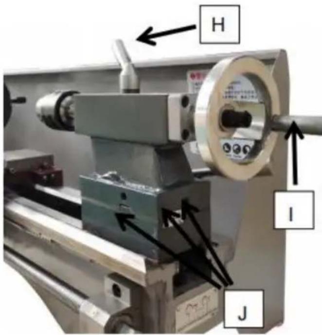
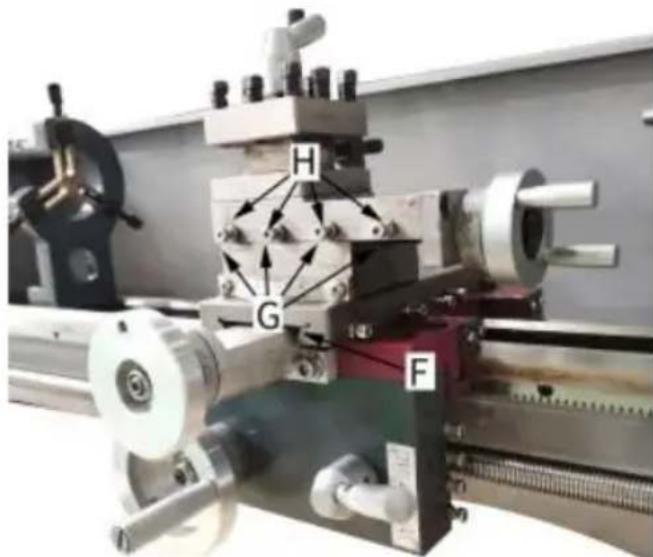
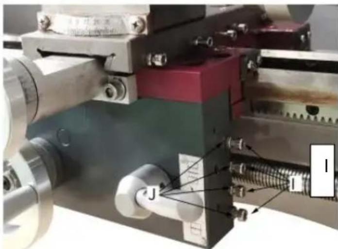
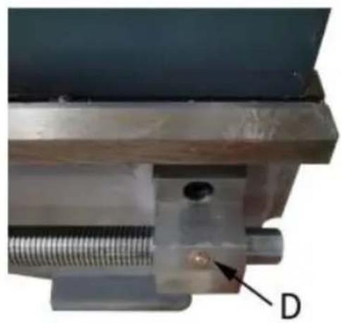
10 . Tailstock Clamping screw (G,Fig. 12)
Turn hex nut clockwise to lock and counter-clockwise to unlock.
11. Tailstock Quill Clamping Lever (H, Fig. 12)
Rotate the lever clockwise to lock the spindle and counter-clockwise to unlock.
12 . Tailstock Quill Traverse Handwheel (I,Fig. 12)
Rotate clockwise to advance the quill. Rotate counter- clockwise to re the quill.
13. Tailstock off-set Adjustment (J, Fig. 12)
Three sets screws located on the tailstock base are used to off-set tailstock for cutting tapers. Loosen lock screw on tailstock end. Loosen side set screw while tightening the other until the amount of off-set indicated on scale. Tighten lock screw.
text_image
H I JFig. 12
OPERATION
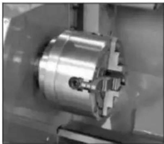
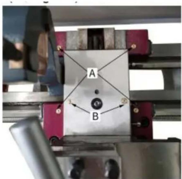
Replacement of Chuck
The head spindle holding fixture is cylindrical. Loose three set screws nuts (A, Fig. 13 only two are shown) on the la the chuck flange to the chuck. Position the new chuck and fix it using the same set scr nuts.
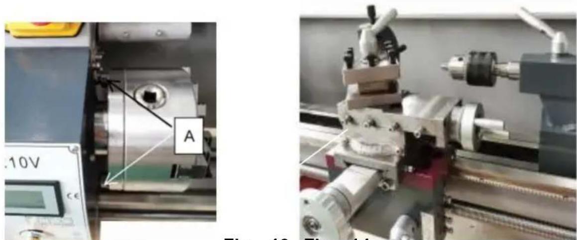
Fig. 13 Fig. 14
TOOL SET UP
Clamp the turning tool into the toolholder.
The tool must be clamped firmly. When turning, the tool has a tender bend under the cutting force generated during the chip formation.
For best results, tool overhang should be kept to a minimum of 3/8" less.
The cutting angle is correct when the cutting edge is inline with the axis of the work piece. The correct height of the tool can be achieved comparing the tool point with the point of the center mounted in the tailstock. If necessary, use steel spacer shims under the tool to get required height. (Fig. 14)
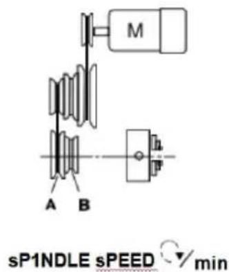
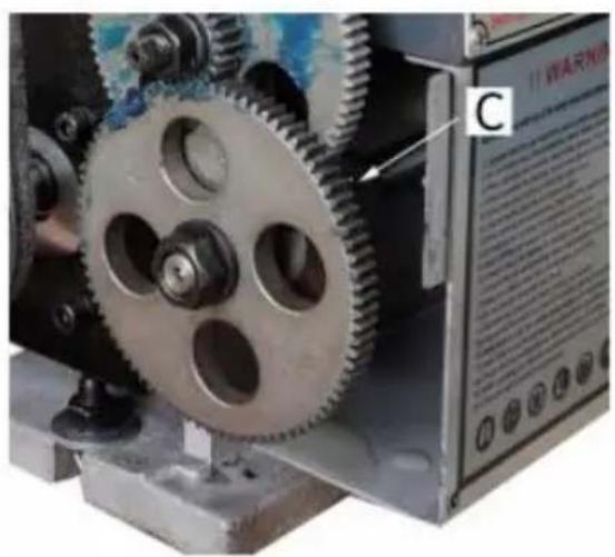
Change Speed
- Unscrew the two fastening screws (B, Fig.15) and remove the protective cover.
- Adjust the V-belt(C, Fig.16) corresponding position.
- Tighten the tension pulley and fasten the nut again.
text_image
M A B sP1NDLE sPEED min| A | B |
| 50.1250 | 100.2500 |
natural_image
Industrial machine with labeled component B, showing internal components and directional arrows (no readable text or symbols)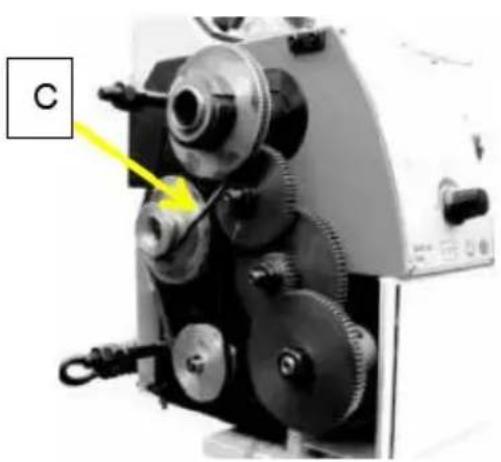
natural_image
Close-up of a mechanical device with gears and a labeled component 'C' (no readable text or symbols beyond label)Fig. 15 Fig. 16
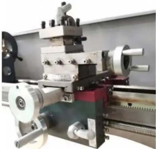
Manual Turning
Apron travel, cross travel, and top slide handwheel can be operated in longitudinal or cross feeding. (Fig.17)
natural_image
Industrial lathe machine with visible control panel and mechanical components (no text or symbols)Fig. 17
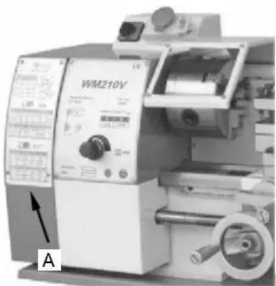
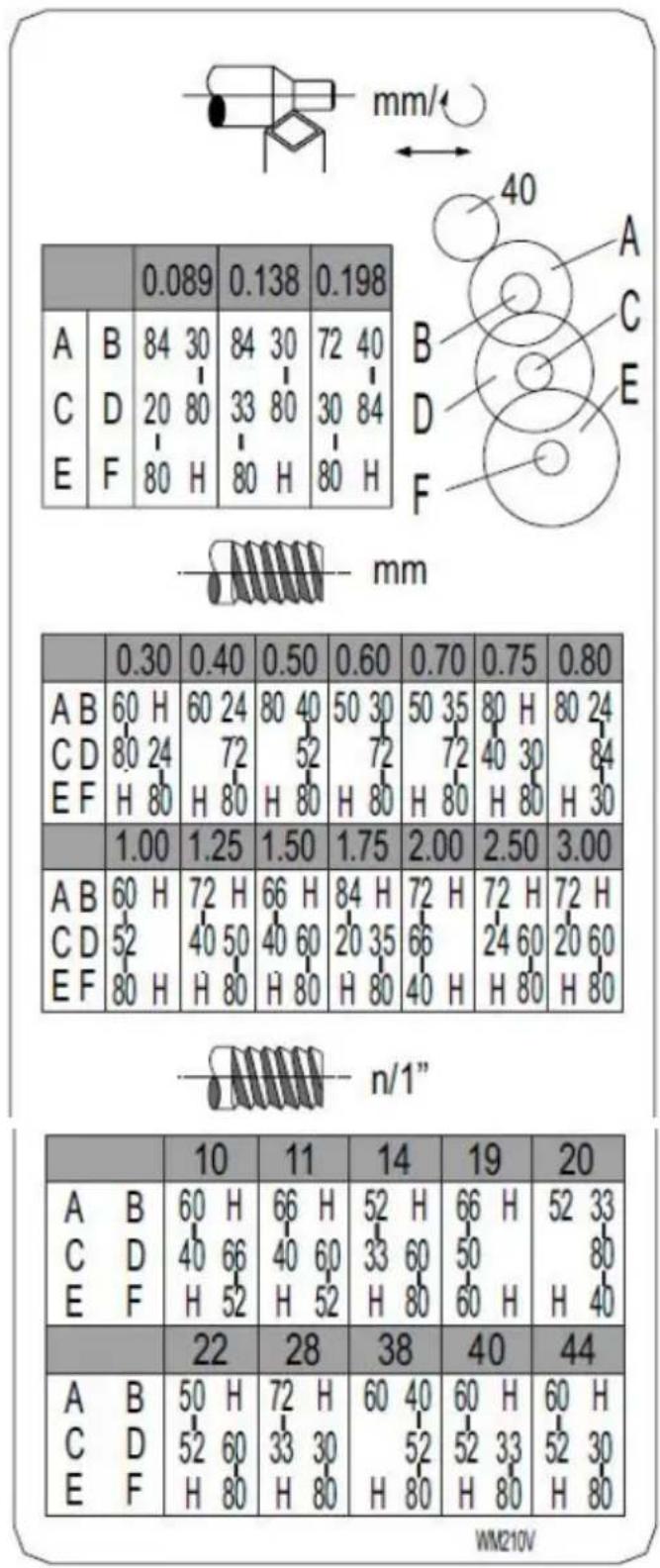
Longitudinal Turning with Auto.Feed
Use the table (A, Fig.18) on the lathe for selecting the feed speed of the thread pitch. Adjust the change gear if the required feed or thread cannot be obtained with the installed gear set.
natural_image
Industrial machine labeled WM210V with control panel and mechanical components (no readable text beyond label)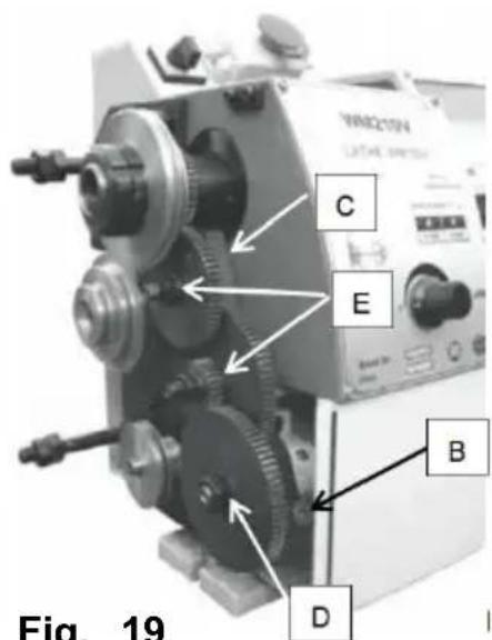
text_image
Fig. 19 C E B DFig. 18 Fig. 19
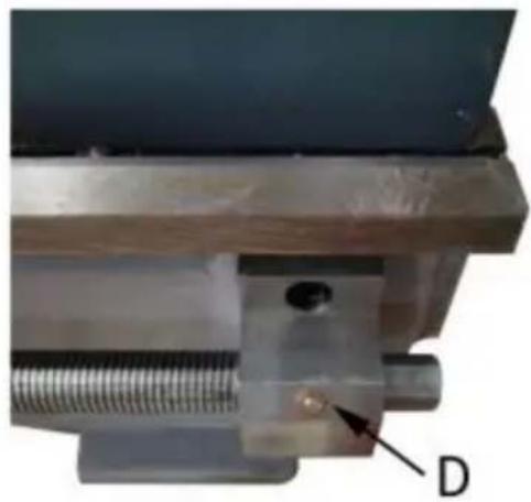
Change Gears Replacement
- Disconnect the machine from the power source.
- Unscrew the two fastening screws and remove the protective cover
- Loosen the locking screw (B, Fig.19) on the quadrant.
- Swing the quadrant (C, Fig. 19) to the right.
- Unscrew the nut (D, Fig.29) from the leadscrew or the nuts (E, F from the quadrant bolts in order to remove the change gears from front.
- Install the gear couples according to the thread and feed table (F and screw the gearwheels onto the quadrant again.
- Swing the quadrant to the left until the gearwheels have engaged
- Readjust gear backlash by inserting a normal sheet of paper as an adjusting or distance aid between the gearwheels.
- Immobilize the quadrant with the locking screw.
- Install the protective cover of the headstock and reconnect the m to the power supply.
THREADINGANDFEEDINGTABLE
other
| Row | Column | Value | |---|---|---| | 1 | A | 0.30 | | 2 | B | 60 | | 3 | C | 80 | | 4 | D | 72 | | 5 | E | 80 | | 6 | F | 1.00 | | 7 | AB | 60 | | 8 | CD | 52 | | 9 | EF | 80 | | 10 | AB | 60 | | 11 | C | 40 | | 12 | D | 66 | | 13 | E | 52 | | 14 | AB | 72 | | 15 | F | 33 | | 16 | AB | 80 | | 17 | C | 52 | | 18 | D | 30 | | 19 | E | 80 | | 20 | AB | 52 | | 21 | C | 40 | | 22 | D | 60 | | 23 | E | 52 | | 24 | AB | 66 | | 25 | C | 33 | | 26 | D | 60 | | 27 | E | 80 | | 28 | AB | 72 | | 29 | C | 52 | | 30 | D | 30 | | 31 | E | 80 | | 32 | AB | 60 | | 33 | C | 40 | | 34 | D | 52 | | 35 | E | 33 | | 36 | AB | 52 | | 37 | C | 30 | | 38 | D | 80 | | 39 | E | 80 | | 40 | AB | 60 | | 41 | C | 40 | | 42 | D | 52 | | 43 | E | 33 | | 44 | AB | 60 | | 45 | C | 52 | | 46 | D | 30 | | 47 | E | 80 | | 48 | AB | 60 | | 49 | C | 40 | | 50 | D | 52 | | 51 | E | 33 | | 52 | AB | 60 | | 53 | C | 40 | | 54 | D | 52 | | 55 | E | 33 | | 56 | AB | 60 | | 57 | C | 40 | | 58 | D | 52 | | 59 | E | 33 | | 60 | AB | 60 | | 61 | C | 40 | | 62 | D | 52 | | 63 | E | 33 | | 64 | AB | 60 | | 65 | C | 40 | | 66 | D | 52 | | 67 | E | 33 | | 68 | AB | 60 | | 69 | C | 40 | | 70 | D | 52 | | 71 | E | 33 | | 72 | AB | 60 | | 73 | C | 40 | | 74 | D | 52 | | 75 | E | 33 | | 76 | AB | 60 | | 77 | C | 40 | | 78 | D | 52 | | 79 | E | 33 | | 80 | AB | 60 | | 81 | C | 40 | | 82 | D | 52 | | 83 | E | 33 | | mm (top) mm (bottom) mm (top) mm (bottom) mm (top) mm (bottom) mm (top) mm (bottom) mm (top) mm (bottom) mm (top) mm (bottom) mm (top) mm (bottom) mm (top) mm (bottom) mm (top) mm (bottom) mm (top) mm (bottom) mm (top) mm (bottom)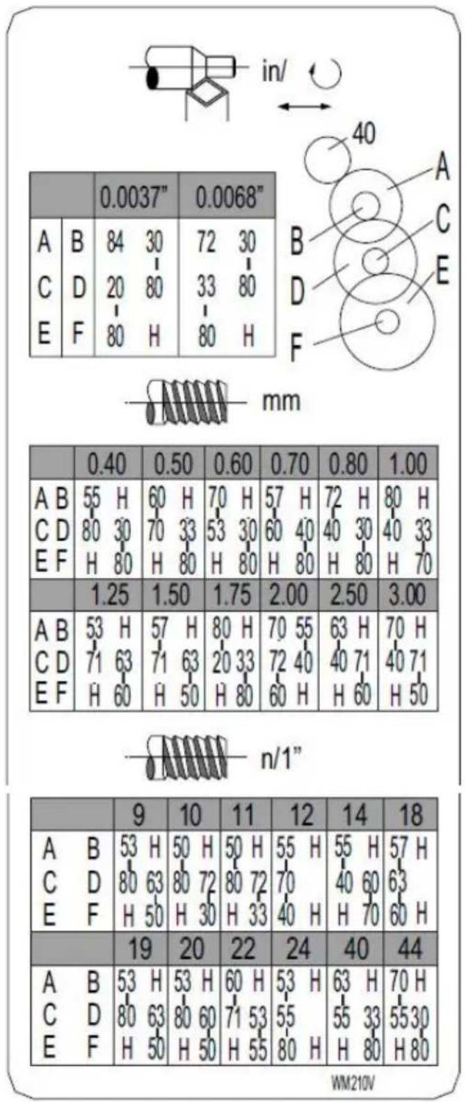
text_image
in/ A B 84 30 72 30 C D 20 80 33 80 E F 80 H 80 H 0.0037" 0.0068" mm A B 55 H 60 H 70 H 57 H 72 H 80 H C D 80 30 70 33 53 30 60 40 40 30 40 33 E F H 80 H 80 H 80 H 80 H 80 H 70 1.25 1.50 1.75 2.00 2.50 3.00 A B 53 H 57 H 80 H 70 55 63 H 70 H C D 71 63 71 63 20 33 72 40 40 71 40 71 E F H 60 H 50 H 80 H 60 H H 60 H 50 n/1" 9 10 11 12 14 18 A B 53 H 50 H 50 H 55 H 55 H 57 H C D 80 63 80 72 80 72 70 E F H 50 H 30 H 33 H 40 H H 70 H 19 20 22 24 40 44 A B 53 H 53 H 60 H 53 H 63 H 70 H C D 80 63 80 60 71 53 H E F H 50 H 50 H 55 H 55 H WM210VFig. 20
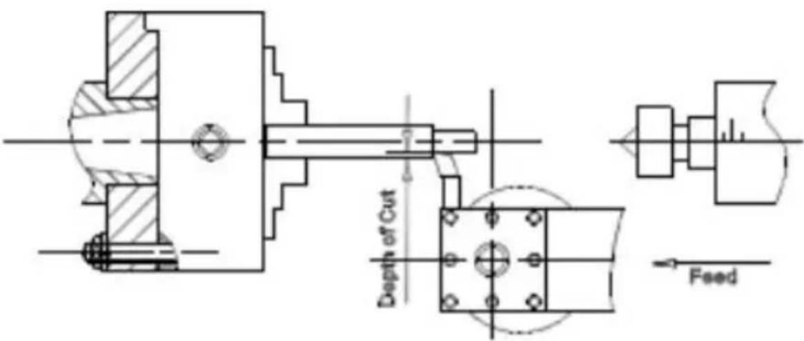
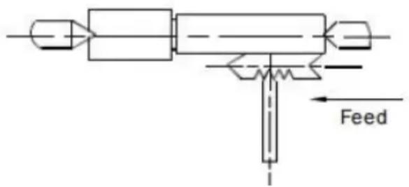
Straight Turning (Fig. 21)
In the straight turning operation, the tool feeds parallel to the axis of rotation of the workpiece. The feed can be either manual by turning handwheel on the lathe saddle or the top slide, or by activating the automatic feed. The crossfeed for the depth of cut is achieved using cross slide.
text_image
Depth of Cut FeedFig. 21
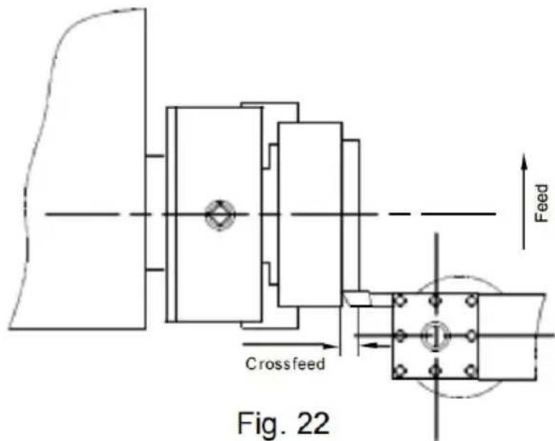
Caching and Oecesses (Fig. 22)
In the facing operation, the tool feeds perpendicular to the axis of ro of the workpiece. The feed is made manually with the cross slide handwheel. The crossfeed for cut depth is made with the top slide o saddle.
text_image
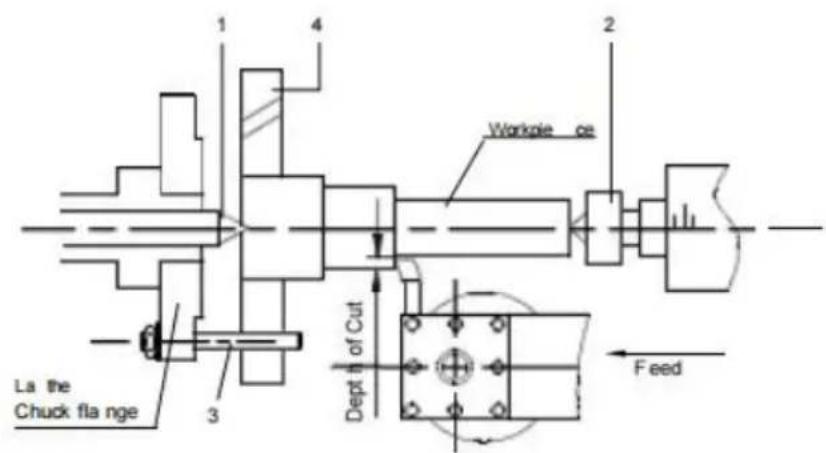
Crossfeed Fig. 22 FeedTurning: Between Benters (Fig. 23)
For turning between centers, it is necessary to remove the chuck from spindle. Fit the M. T. 3 center into the spindle nose and the M.T. 2 into the tailstock. Mount the workpiece fitted with the driver dog between the centers. The driver is driven by a catch or face plate.
Note: Always use a small amount of grease on the tailstock ce prevent center tip from overheating.
text_image
La the Chuck flange 1 4 2 Workpiece ce Dept h of Cut Feed- Fixed Centre 60°
- Living Centre 60°
- Dog Drive Pin
- Dog Plate
Fig. 23
Taper Turning Using Tailstock Off-Set
La the Work to a side angle of 5 can be turned by off- setting the The angle depends on the length of the workpiece.
To off-set the tailstock, loosen locking screw (A, Fig.24).
Unscrew the set screw (B, Fig.24) on right end of the tailstock. Loos front adjusting screw( C, Fig.24 ) and take up the same amount by tightening the rear adjusting screw (D, Fig.24) until the desired taper been reached. The desired cross- adjustment can be read off the sca Fig.24 ). First retighten the set screw (B, Fig,24) and then the two ( and rear) adjusting screw to lock the tailstock in position. Retighten the locking screw (A, Fig.24) of the tailstock. The workpiece must be held between to centers and driven by a face plate and driver dog.
After taper turning, the tailstock should be returned to its original pos according to the zero position on the scale of tailstock. (E, Fig.24)
text_image
Labeled mechanical device diagram with components A through E marked for identificationFig. 24
Thread Cutting
Set the machine up to the desired thread pitch (according to the thread chart, Fig.20). Start the machine and engage the half nut. When the reaches the part, it will cut the initial threading pass. When the tool the end of the cut, stop the machine by turning the motor off and a same time back the tool out of the part so that it clears the thread disengage the half nut lever. Reverse the motor direction to allow the cutting tool to traverse back to the starting point. Repeat these steps you have obtained the desired results.
NOTES
Example: Male Thread
- The workpiece diameter must have been turned to the diameter of desired thread.
- The workpiece requires a chamfer at the beginning of the thread a an undercut at the thread runout.
- The speed must be as low as possible. The change gears must have been installed according to the required pitch.
- The thread cutting tool must be exactly the sample shape as the thread, must be absolutely rectangular and clamped so that it coincides exactly with the turning enter.
- The thread is produced in various cutting steps so that the cutting has to be turned out of the thread completely (with the cross slide the end of each cutting step.
- The tool is withdrawn with the leadscrew nut engaged by inverting change-over switch.
- Stop the machine and feed the thread cutting tool in low cut depth using the cross slide. Before each passage, place the top slide approximately 0.2 to 0.3mm to the left and right alternately in order to cut the thread free. This way, the thread cutting tools cuts only of thread flank with each passage. Keep cutting the thread free until have almost reached the full depth of thread.
text_image
FeedFig. 25
Lathe Accessories
Three Jaw Universal Lathe Chuck
Using this universal chuck round triangular square hexagonal octagonal and twelve, cornered stock may be clamped. (Fig.26)
Note: new lathes have very tight fitting jaws. This is necessary to ensure accurate clamping and long service life- with repeated opening and close the jaw adjust automatically and their operation becomes progressively Smoother.
Note:
For the original 3 jaw chuck that mounted on the lathe the factory I mounted the chuck in the best way to guarantee the holding accurate two "." mark (A) Fig.26 showed on the chuck and chuck flange.
natural_image
Close-up of a mechanical component with a labeled 'E' and arrow indicator (no readable text or symbols beyond the label)Fig. 26
There are two types of jaws: Internal and external jaws- Please note the number of jaws fit with the number inside the chuck,s groove. Do mix them together. When you are going to mount them please mount in ascending order 0, 1 , 3 when you are going to take them out I take them out in descending order 3,1,0 one by one- After you finish procedure rotate the jaws to the smallest diameter and check that the three jaws are well fitted.
Four Jaw Independent Lathe Chuck
This special chuck has four independently adjustable chuck jaws- Thes permit the holding of asymmetrical pieces and enable the accurate se of cylindrical pieces. (Fig.27)
natural_image
Close-up of a metallic industrial machine component (no visible text or symbols)Fig. 27
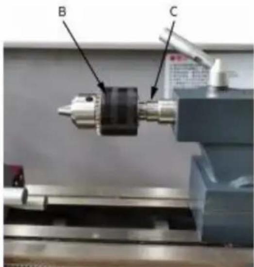
Drill Chuck (optional)
Use the drill chuck to hold centering drills and twist drills in the tails (Fig.28)
Morse Taper Arbor (optional)
An arbor is necessary for mounting the drill chuck in the tailstock. It No. 1 Morse taper. (C) Fig.28
text_image
B CFig. 28
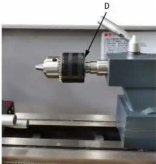
Live Center (optional)
The live center is mounted in ball bearings- Its use is highly recommend for turning at speeds in excess of 6.RPM. ( Fig.29)
natural_image
Close-up of a mechanical tool with a labeled component 'D' pointing to a cylindrical component (no visible text or symbols beyond label)Fig. 29
Steady Rest
The steady rest serves as a support for shafts on the free tailstock many operations the tailstock can not be used as it obstructs the tur tool or drilling tool, and therefore, must be removed from the machine steady rest, which function as an end support, ensures chatter- free operation. The steady rest is mounted on the bedways and is secure below with a locking plate. The sliding fingers require continuous lubrication at the contact points to prevent premature wear. (Fig.30)
text_image
A B CFig. 30
Setting the Steady Rest
- Loosen three hex nuts. (A, Fig.31)
- Loosen knurled screw (B, Fig.36) and open the sliding fingers. (C, Fig.31) until the steady rest can be moved with its finger the workpiece. Secure the steady rest in position.
- Tighten knurled screws so that fingers are snug but not tight ag workpiece. Tighten three nuts (A, Fig.31). Lubricate the sliding points machine oil.
- When, after prolonged operation, the jaw show wear, the tips of the fingers may be filed or remilled.
Follow Rest
The follow rest is mounted on the saddle and follows the movement turning tool. only two sliding fingers are required. The place of the finger is taken by the turning tool. The follow rest is used for turning operations on long, slender workpieces. 1t prevents flexing of the workpiece under pressure from the turning tool. ( Fig.31 )
Set the fingers snug to the workpiece but not overly tight. Lubricate fingers during operation to prevent premature wear.
natural_image
Close-up of a metal lathe machine with a blue clamp and red base (no visible text or symbols)Fig. 31
ADJUSTMENTS
After a period time, wear in some of the moving components may not be adjusted.
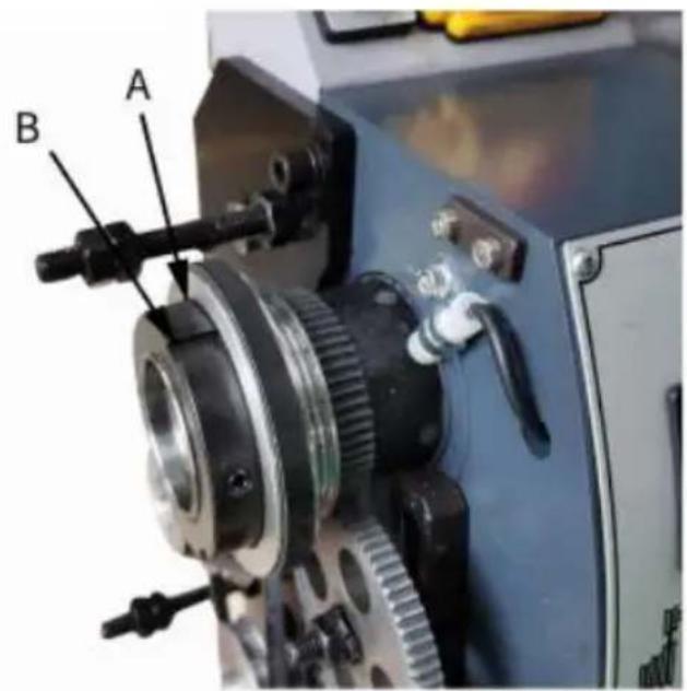
Main spindle Bearings
The main spindle bearings are adjusted at the factory. 1f end play be evident after considerable use, the bearings may be adjusted.
Fasten the slotted nut (A, Fig.32) on the back of the spindle, loosen outer slotted nut (B, Fig.32). Adjust the slotted nut (A, Fig.32) until a play is taken up. The spindle should still revolve freely. Fasten the slotted nut (A, Fig.32) again and tighten the outer slotted nut (B, Fig
Caution: excessive tightening or preloading will damage the bearings.
text_image
A BFig. 32
Adjustment of Cross slide
The cross slide is fitted with a gib strip(C, Fig.33) and can be adjusted to adjust screws (D, Fig.33) fitted with lock nuts. (E, Fig.33) Loosen the lock 1 and tighten the set screws until slide moves freely without play. Tight lock nuts to retain adjustment.
natural_image
Close-up of a mechanical assembly with metallic components and a cylindrical shaft (no visible text or symbols)Fig. 33
Adjustment of Top slide
The top slide is fitted with a gib strip(F, Fig.34) and can be adjusted screws (G, Fig. 34) fitted with lock nuts. (H, Fig. 34) Loosen the lock and tighten the set screws until slide moves freely without play. Tight lock nuts to retain adjustment.
text_image
H G FFig. 34
Adjustment of Half Nut Guide
The half nuts engagement can be adjusted with screws (I, Fig.35) fitt with lock nuts (J, Fig.35). Loosen the nuts on the right side of the and adjust the control screws until both half nuts move freely without Tighten the nut.
text_image
Labeled mechanical assembly diagram showing components J and I with annotations and arrows indicating parts of a machine or tool.Fig. 35

CAUT10N
Lathe must be serviced at all lubrication points and all reservoirs filled to operating level before the lathe is placed into servicel
Failure to comply may cause serious damage
NOTES:
Lubricate all slideways lightly before every use. Lubricate the change gears and the leadscrew slightly with a lithium-based grease.
1. Carriage
Lubricate Four oil ports (A, Fig. 36) with 20W machine oil once daily
2. Cross Slide
Lubricate two oil ports (B , Fig. 36 ) with 20W machine oil once da
text_image
A BFig. 36
3. Leadscrew
Lubricate the left oil port ( C Fig. 37) and right oil port (D, Fig.38) machine oil once daily.
natural_image
Mechanical gear assembly with visible meshing and a label 'C' (no readable text or symbols on the gears)Fig. 37 Fig. 38
natural_image
Close-up of a mechanical assembly with a threaded component and labeled point D (no readable text or symbols)Electricity
WARNING!
Connection of the lathe and all other electrical work may only be out by an authorized electrician!
Failure to comply may cause serious injury and damage to the m and property!
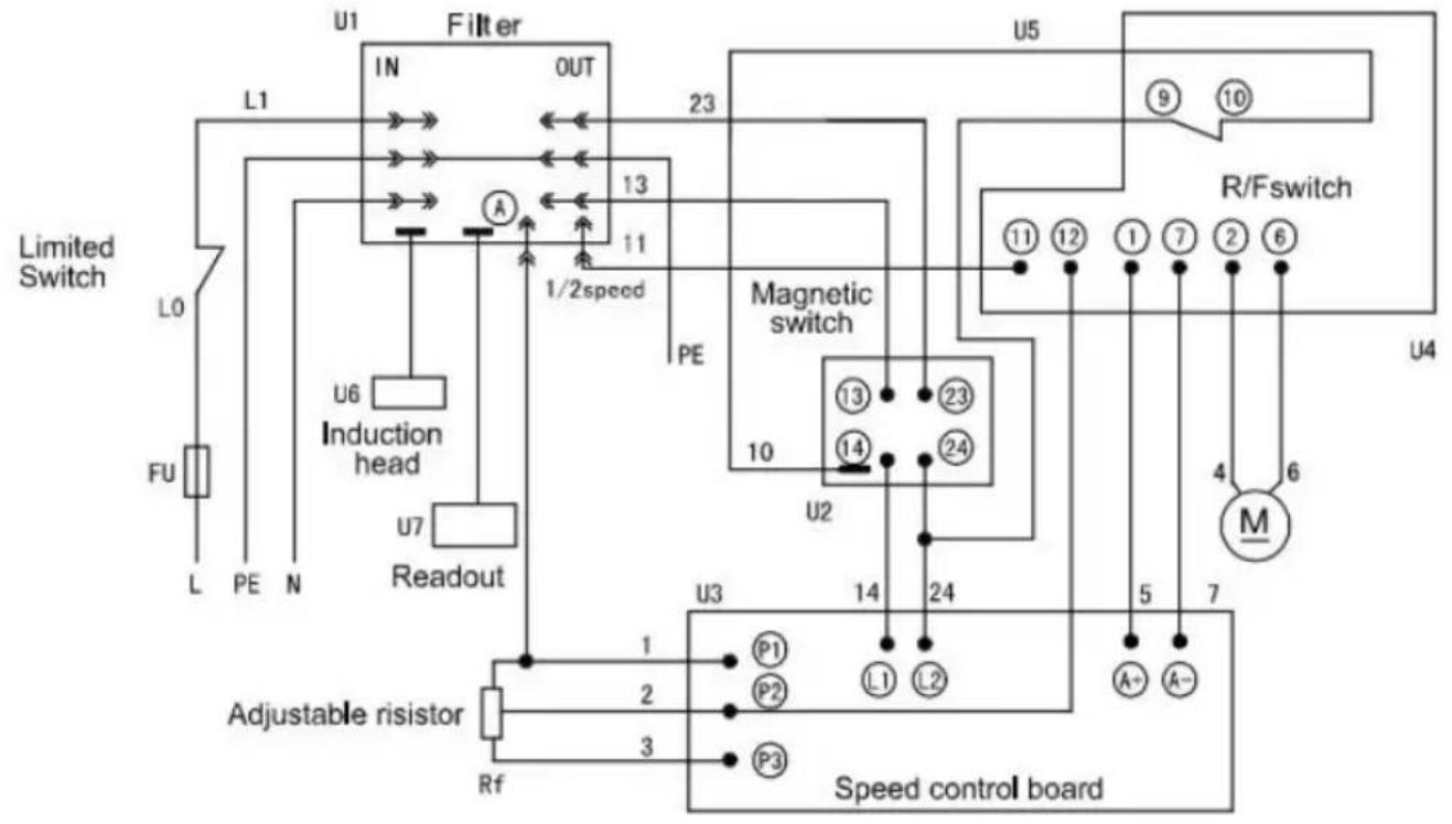
The WM210V Lathe is rated at 550W, 1PH, 110V/220V only. Confirm power available at the lathe's location is the same rating as the lat. Using the wiring diagram (Fig. 39) for connecting the lathe to the supply. Make sure the lathe in properly grounded.
The following is wiring diagram of the lathe: (Fig.39)
flowchart
graph TD
    A["Limited Switch"] --> B["L1"]
    A --> C["L0"]
    A --> D["FU"]
    B --> E["Filter"]
    C --> E
    D --> E
    E --> F["IN"]
    F --> G["OUT"]
    G --> H["1/2speed"]
    H --> I["Magnetic switch"]
    I --> J["U5"]
    I --> K["R/Fswitch"]
    K --> L["U4"]
    I --> M["M"]
    M --> N["M"]
    I --> O["13"]
    I --> P["11"]
    I --> Q["10"]
    I --> R["10"]
    I --> S["10"]
    I --> T["10"]
    I --> U["10"]
    I --> V["10"]
    I --> W["10"]
    I --> X["10"]
    I --> Y["10"]
    I --> Z["10"]
    I --> AA["10"]
    I --> AB["10"]
    I --> AC["10"]
    I --> AD["10"]
    I --> AE["10"]
    I --> AF["10"]
    I --> AG["10"]
    I --> AH["10"]
    I --> AI["10"]
    I --> AJ["10"]
    I --> AK["10"]
    I --> AL["10"]
    I --> AM["10"]
    I --> AN["10"]
    I --> AO["10"]
    I --> AP["10"]
    I --> AQ["10"]
    I --> AR["10"]
    I --> AS["10"]
    I --> AT["10"]
    I --> AU["10"]
    I --> AV["10"]
    I --> AW["10"]
    I --> AX["10"]
    I --> AY["10"]
    I --> AZ["10"]
    I --> BA["10"]
    I --> BB["10"]
    I --> BC["10"]
    I --> BD["10"]
    I --> BE["10"]
    I --> BF["10"]
    I --> BG["10"]
    I --> BH["10"]
    I --> BI["10"]
    I --> BJ["10"]
    I --> BK["10"]
    I --> BL["10"]
    I --> BM["10"]
    I --> BN["10"]
    I --> BO["10"]
    I --> BP["10"]
    I --> BQ["10"]
    I --> BR["10"]
    I --> BS["10"]
    I --> BT["10"]
    I --> BU["10"]
    I --> BV["10"]
    I --> BW["10"]
    I --> BX["10"]
    I --> BY["10"]
    I --> BZ["10"]
    I --> CA["10"]
    I --> CB["10"]
    I --> CC["10"]
    I --> CD["10"]
    I --> CE["10"]
    I --> CF["10"]
    I --> CG["10"]
    I --> CH["10"]
    I --> CI["10"]
    I --> CJ["10"]
    I --> CK["10"]
    I --> CL["10"]
    I --> CM["10"]
    I --> CN["10"]
    I --> CO["10"]
    I --> CP["10"]
    I --> CQ["10"]
    I --> CR["10"]
    I --> CS["10"]
    I --> CT["10"]
    I --> CU["10"]
    I --> CV["10"]
    I --> CW["10"]
    I --> CX["10"]
    I --> CY["10"]
    I --> CZ["10"]
Fig. 39
MAINTENANCE
Keep the maintenance of the machine tool during the operation to guarantee the accuracy and service life of the machine tool.
- In order to retain the machine's precision and functionality. it essential to treat it with care. keep it clean and grease and lu it regularly. Only through good care. you can be sure that the working quality of the machine will remain constant.
NOTES: Disconnect the machine plug from the mains supply whenever you carry out cleaning, maintenance or repair work!
Oil, grease and cleaning agents are pollutants and must not be disposed of through the drains or in normal refuse. Dispose of the agents in accordance with current legal requirements on the environment. Cleaning rags impregnated with oil, grease and cleaning agents are easily inflammable. Collect cleaning rags or
cleaning wool in a suitable closed vessel and dispose of them in environmentally sound way - do not put them with normal refuse
-
Lubrication all slideways lightly before every use. The change gears and the leadscrew must also be lightly lubricated with lit base grease.
-
During the operation, the chips which falls onto the sliding suit should be cleaned timely. and the inspection should be often not to prevent chips falling into the position between the machine to saddle and lathe bed guide way. Asphalt felt should be cleaned certain time.
NOTES: Do not remove the chips with your bare hands. There is of cuts due to sharp.edged chips. Never use flammable solvents cleaning agents or agents that generate noxious fumes!
Protect electrical components such as motors, switches, switch boxes, etc., against humidity when cleaning.
-
After the operation every day, eliminate all the chips and clean different part of the machine tool and apply machine tool oil to prevent rusting.
-
In order to maintain the machining accuracy. take care of the surface of the machine tool for the chuck and the guide was avoid mechanical damage and the wear due to improper guide.
-
If the damage is found, the maintenance should be done immediately.
NOTES: Repair work may only be carried out by qualified person with the corresponding mechanical and electrical knowledge.
TROUBLESHOOTING
| Problem | Possible Reason | Elimination |
| Surface of work piece too rough | Tool blunt | Re.sharpen tool |
| Tool springs | Clamp tool with less overhang | |
| Feed too high | Reduce feed | |
| Radius at the tool tip too small | Increase radius | |
| Workpiece becomes coned | Centers are not aligned (tailstock has offset) | Adjust tailstock to the center |
| Top slide not aligned well (cutting with the top slide) | Align top slide well | |
| Lathe is chatterin | Feed too high | Reduce feed |
| Slack in main bearing | Adjust the main bearing | |
| Center runs hot | Workpiece has expanded | Loosen tailstock center |
| Tool has a short edge | Cutting speed too high | Reduce cutting speed |
| Tool has a short Life | Crossfeed too high | Lower crossfeed(finishing allowance should not exceed 0.5mm) |
| Insufficient cooling | More coolant | |
| Flank wear too high | Clearance angle too small | 1increase clearance angle |
| Tool tip not adjusted to center high | Correct height adjustment of the | |
| Cutting edge breaks off | Wedge angle too small (heat build.up) | Increase wedge angle |
| Grinding crack due to wrong cooling | Cool uniformly | |
| Excessive slack in the spindle bearing | Adjust the slack in the spindle bearing | |
| Arrangement (vibrations) | Arrangement | |
| Cut thread is wrc | Tool is clamped incorrectly or has | Adjust too to the center |
| Been started grinding the wrong way | Grind angle correctly | |
| Cut thread is wrc | Wrong pitch | Adjust the right pitch |
| Wrong diameter | Turn the workpiece to the correct diameter | |
| Spindle does not activate | Emergency stop switch activated | Unlock emergency stop switch |
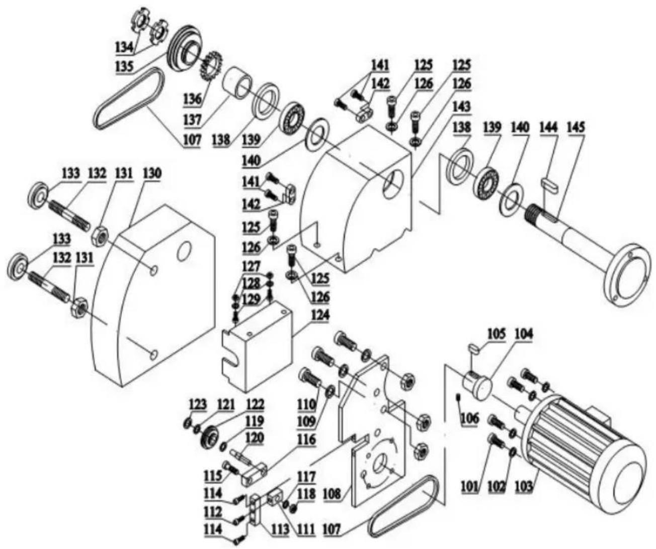
Headstock Assembly
text_image
Exploded view diagram of a mechanical assembly with numbered parts for identification| Parts No. | Description | specification | Qty | Parts No. | Description | specification | Qty | |
| 101 | Screw | M5x25 | 4 | 123 | Spring Ring | 22xl | I | |
| 102 | Washer | 4 | 124 | Cover | I | |||
| 103 | DC Motor | 83ZY005A | I | 125 | Screw | M8x25 | 4 | |
| 104 | Motor Puller | I | 126 | Washer | 8 | 4 | ||
| 105 | Key | A4x4x20 | I | 127 | Nut | M8 | 2 | |
| 106 | Screw | M6x8 | I | 128 | Washer | 8 | 2 | |
| 107 | Belt | Gates-5M- 360 | 2 | 129 | Screw | M8 | 2 | |
| 108 | Bracket Plate | I | 130 | Belt Cover | I | |||
| 109 | Washer | 8 | 3 | 131 | Nut | MI0 | 2 | |
| 110 | Screw | M8x20 | 3 | 132 | Bolt | MI0x80 | 2 | |
| 111 | Block | I | 133 | Nut | MI0 | 2 | ||
| 112 | Screw | M6x30 | I | 134 | Nut | M27xl | 2 | |
| 113 | Block | I | 135 | Spindle Puller | I | |||
| 114 | Screw | M6x20 | I | 136 | Gear | 40T | I | |
| 115 | Bolt | I | 137 | Separator | I | |||
| 116 | Block | I | 138 | Gasket | I | |||
| 117 | Washer | I | 139 | Bearing | 30206 | I | ||
| 118 | Nut | I | 140 | Grease Cover | I | |||
| 119 | Spring Ring | 8x0.8 | I | 141 | Screw | M4xl0 | 2 | |
| 120 | Bolt | I | 142 | Block | I | |||
| 121 | Bearing | I | 143 | Headstock | I | |||
| 122 | Pulley | I | 144 | Key | A3x3xl5 | I |
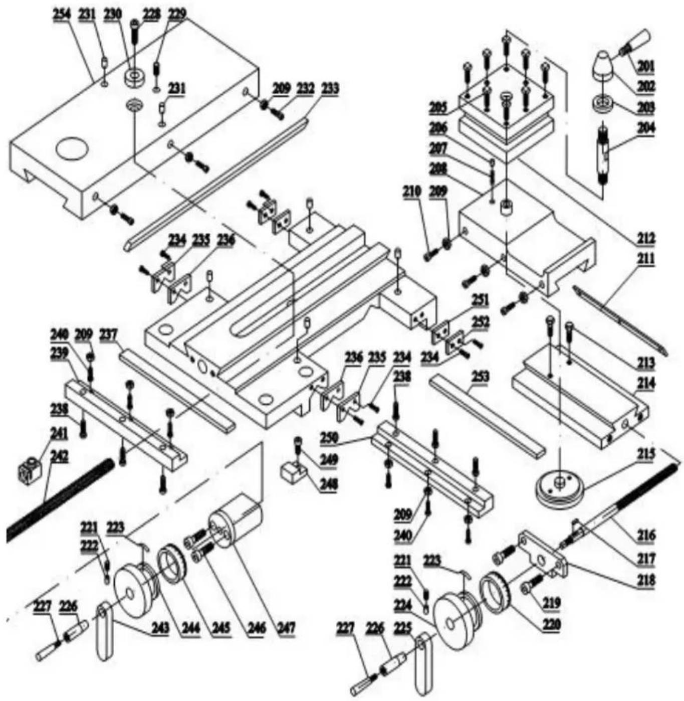
Top slide, Cross slide, Carriage Assembly
text_image
Exploded view diagram of a mechanical assembly with numbered components and assembly details| Parts No. | Description | Specification | Qty | Parts No. | Description | Specification | Qty | |
| 201 | Handle | 1 | 228 | Screw | M4x8 | 1 | ||
| 202 | Handle Base | 1 | 229 | Screw | M5x10 | 1 | ||
| 203 | Washer | 1 | 230 | Bush | 1 | |||
| 204 | Bolt | 1 | 231 | oil Cup | Φ5 | 2 | ||
| 205 | Screw | M6x25 | 1 | 232 | Screw | M4x20 | 3 | |
| 206 | Pin | 1 | 233 | Gib | 1 | |||
| 207 | Spring | 5x10x1 | 1 | 234 | Screw | 8 | ||
| 208 | Longitudinal Slide | 1 | 235 | Wiper Cover | 2 | |||
| 209 | Nut | M4 | 9 | 236 | Wiper | 2 | ||
| 210 | Screw | M4x14 | 3 | 237 | Gib | 1 | ||
| 211 | Gib | 1 | 238 | Screw | 6 | |||
| 212 | Top Rest | 1 | 239 | Sliding Block | 1 | |||
| 213 | Screw | M5x30 | 1 | 240 | Screw | M4x10 | 6 | |
| 214 | Swivel Base | M6x20 | 1 | 241 | Nut | 1 | ||
| 215 | Micrometer Pan | 1 | 242 | Lead Screw | 1 | |||
| 216 | Lead Screw | 1 | 243 | Handle Block | 1 | |||
| 217 | Key | 3x12 | 1 | 244 | Handlewheel | 1 | ||
| 218 | Bracket | 1 | 245 | Collar | 1 | |||
| 219 | Screw | M5x12 | 2 | 246 | Screw | M6x50 | 2 | |
| 220 | Collar | 1 | 247 | Bracket | 1 | |||
| 221 | Screw | 2 | 248 | Clamping Plate | 1 | |||
| 222 | Pin | 2 | 249 | Screw | 1 | |||
| 223 | Spring | 2 | 250 | Sliding Block | 1 | |||
| 224 | Handwheel | 1 | 251 | Wiper | 2 | |||
| 225 | Handle Block | 1 | 252 | Wiper Cover | 2 | |||
| 226 | Handle Sleeve | 2 | 253 | Gib | 1 | |||
| 227 | Handle | 2 | 254 | Cross Slide | 1 |
Apron Assembly
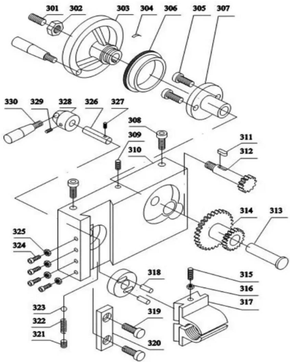
text_image
Exploded view diagram of a mechanical assembly with numbered parts for identification| Parts No. | Description | Specification | Qty | Parts No. | Description | Specification | Qty | |
| 301 | Screw | M8x8 | 1 | 317 | Half Nut | 1 | ||
| 302 | Nut | M8 | 1 | 318 | Pin | ∅ 4x10 | 1 | |
| 303 | Handwheel | 1 | 319 | Screw | M4x10 | 2 | ||
| 304 | Spring | 1 | 320 | Block | 1 | |||
| 305 | Screw | M5x10 | 2 | 321 | Screw | M6x8 | 1 | |
| 306 | Collar | 1 | 322 | Spring | 0.6x 3.5x12 | 1 | ||
| 307 | Bracket | 1 | 323 | Ball | ∅ 4.5 | 2 | ||
| 308 | Screw | M8x25 | 2 | 324 | Screw | M4x12 | 4 | |
| 309 | Screw | M5x8 | 1 | 325 | Nut | M4 | 1 | |
| 310 | Apron | 1 | 326 | Shaft | 1 | |||
| 311 | Key | A3x3x8 | 1 | 327 | Pin | ∅3x30 | 2 | |
| 312 | Gear Shaft | 14T | 1 | 328 | Hand Base | 1 | ||
| 313 | Shaft | 1 | 329 | Screw | M5X6 | 1 | ||
| 314 | Gear | 44/21T | 1 | 330 | Handle | 1 | ||
| 315 | Screw | M4x35 | 1 | 331 | Handle | 1 | ||
| 316 | Nut | M4 | 1 | 317 | Half Nut | 1 |
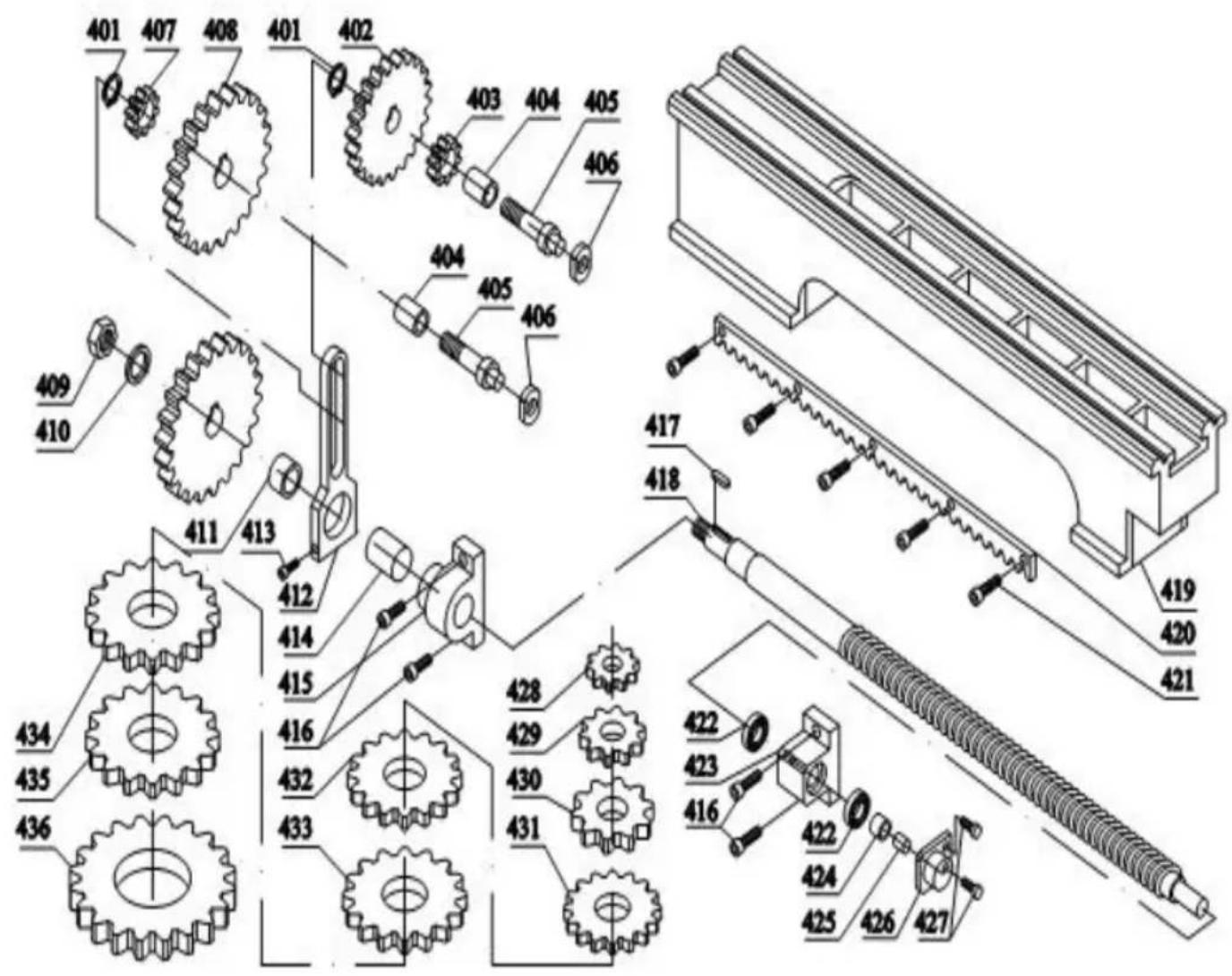
Bed, hanging wheel parts Assembly
text_image
Technical diagram of mechanical gear assembly with numbered components and exploded view| Parts No. | Description | Specification | Qty | Parts No. | Description | Specification | Qty | |
| 401 | Spring Ring | 2 | 419 | Bed | 1 | |||
| 402 | Gear | 60T | 1 | 420 | Rack | 1 | ||
| 403 | Gear | 20T | 1 | 421 | Screw | M2x12 | 5 | |
| 404 | Bush | 1 | 422 | Bearing | 51100 | 2 | ||
| 405 | Bolt | 1 | 423 | Right Support | 1 | |||
| 406 | Nut | M8 | 1 | 424 | Nut | 1 | ||
| 407 | Gear | 24T | 1 | 425 | Screw | M8x6 | 1 | |
| 408 | Gear | 80T | 1 | 426 | Cover | 1 | ||
| 409 | Nut | M10 | 1 | 427 | Screw | M4x12 | 2 | |
| 410 | Washer | 10 | 1 | 428 | Gear | 25T | 1 | |
| 411 | Bush | 1 | 429 | Gear | 30T | 1 | ||
| 412 | Frame | 1 | 430 | Gear | 33T | 1 | ||
| 413 | Screw | M6x35 | 1 | 431 | Gear | 35T | 1 | |
| 414 | Bush | 1 | 432 | Gear | 40T | 1 | ||
| 415 | Left Support | 1 | 433 | Gear | 45T | 1 | ||
| 416 | Screw | M6x14 | 2 | 434 | Gear | 50T | 1 | |
| 417 | Key | A3x3x16 | 1 | 435 | Gear | 52T | 1 | |
| 418 | Lead Screw | 1 | 436 | Gear | 66T | 1 |
Tailstock Assembly

text_image
Exploded view diagram of a mechanical assembly with numbered parts for identification| Parts No. | Description | Specification | Qty | Parts No. | Description | Specification | Qty | |
| 501 | Handle | 1 | 515 | Nut | M8 | 1 | ||
| 502 | Handle Base | 1 | 516 | Screw | M8x6 | 1 | ||
| 503 | Lock Base | 1 | 517 | Handle Screw | 1 | |||
| 504 | Sleeve | 1 | 518 | Handle Sleeve | 1 | |||
| 505 | Tailstock | 1 | 519 | Screw | M5x12 | 1 | ||
| 506 | Lead Screw | 1 | 520 | Adjustment Block | 1 | |||
| 507 | Key | A3x3x8 | 1 | 521 | Screw | M6x12 | 1 | |
| 508 | Nut | M6 | 1 | 522 | Base | 1 | ||
| 509 | Screw | M6x14 | 1 | 523 | Spring | 1 | ||
| 510 | Bearing | 51100 | 1 | 524 | Clamping Plate | 1 | ||
| 511 | Housing | 1 | 525 | Bolt | M10x70 | 1 | ||
| 512 | Collar | 1 | 526 | Screw | M6x16 | 2 | ||
| 513 | Spring | 1 | 527 | washer | ∅ 10 | 1 | ||
| 514 | Handwheel | 1 | 528 | Nut | M10 | 1 |
Manufacturer: Shanghaimuxinmuyeyouxiangongsi
Address: Shuangchenglu 803nong11hao1602A-1609shi, baoshanqu, shanghai 200000 CN.
Imported to USA: Sanven Technology Ltd., Suite 250, 9166 Anaheim Pla Rancho Cucamonga, CA 91730
| EC | REP |
E-CrossStu GmbH
Mainzer Landstr.69, 60329 Frankfurt am Ma
| UK | REP |
YH CONSULTING LIMITED.
C/O YH Consulting Limited Office 147, Centurion H
London Road. Staines-upon-Thames. Surrey. TW18 4
VEVOR®
TOUGH TOOLS, HALF PRICE
Technical Support and E-Warranty Certificate
www.vevor.com/support
VEVOR®
TOUGH TOOLS, HALF PRICE
natural_image
Industrial machine with visible control panel and warning label (no readable text or symbols on the machine itself)natural_image
Collection of mechanical tools and components including wrenches, screwdrivers, and a green base case (no text or symbols visible)Fig. 1
natural_image
Industrial machine with dual gears and control panel (no visible text or symbols)Fig. 3
Tête (Fig. 4)
natural_image
Close-up of a mechanical lathe machine with no visible text or symbolsFig. 5
Tablier (Fig. 6)
natural_image
Close-up of a mechanical lathe machine with a circular component and a close-up inset showing a mechanical part (no visible text or symbols)Fig. 6
La vis mère
natural_image
Close-up of a mechanical cutting machine with labeled parts A and B (no readable text or symbols beyond labels)Fig.7
Contre-pointe (Fig. 8)
natural_image
Industrial machine with a large cylindrical component and a labeled section (C), no visible text or symbols on the machinery itself.Fig.8
Avis:
natural_image
Close-up of a mechanical assembly with metallic components and a labeled component 'A' (no readable text or symbols beyond label)Fig.10Fig.9
natural_image
Industrial lathe machine with visible gears and shafts (no text or symbols)Fig. 14Fig. 1:
CONFIGURATION DE L'OUTIL
natural_image
Industrial machine with labeled component B, showing control panel and buttons (no readable text or symbols beyond label)
natural_image
Close-up of a mechanical device with gears and a labeled component 'C' (no readable text or symbols beyond label)Fig. 16Fig. 15
Tournage manuel
natural_image
Industrial lathe machine with visible control panel and mechanical components (no readable text or symbols)Fig. 17
natural_image
Industrial machine labeled WM210V with control panel and mechanical components (no readable text beyond label)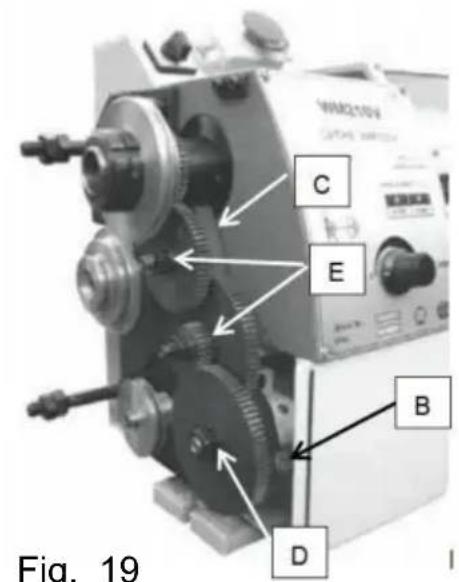
text_image
C E B D Fig. 19Fig. 18 Fig. 19
text_image
Depth of Cut FeedFig. 21
text_image
La the Chuck flange 3 1 4 2 Workpiece ce Dept h of Cut Feed-
Fixed Centre 60°
-
Living Centre 60°
-
Dog Drive Pin
-
Dog Plate
Fig. 23
text_image
Labeled photograph of a lathe machine with numbered components A through EFig. 24
Coupe de filetage
natural_image
Close-up of a mechanical tool component with a labeled 'E' and an arrow pointing to a circular feature (no readable text or symbols beyond the label)Fig. 26
natural_image
Close-up of a metallic industrial machine component (no visible text or symbols)Fig. 27
natural_image
Close-up of a mechanical assembly with a labeled component 'D' pointing to a shaft (no visible text or symbols beyond label)Fig. 29
Lunette fixe. La
natural_image
Close-up of a metal clamp and mechanical assembly with no visible text or symbolsFig. 31
ADJUSTMENTS
natural_image
Close-up of a mechanical lathe machine with visible gears and shafts (no text or symbols)Fig. 33
natural_image
Mechanical assembly with labeled components (J, I) and no readable text or symbols beyond labelsFig. 35
LUBR1CAT10N

CAUT10N
Lathe must be serviced at all lubrication points and all reservoirs filled to operating level before the lathe is placed into servicel
Failure to comply may cause serious damage
REMARQUES :
natural_image
Close-up of a mechanical gear assembly with visible teeth and mounting base (no text or symbols)Fig. 37
natural_image
Close-up of a mechanical assembly with a threaded component and a labeled part 'D' (no readable text or symbols beyond label)Fig. 38
Électricité
! AVERTISSEMENT!
text_image
Exploded view diagram of a mechanical assembly with numbered parts for identificationtext_image
Exploded view diagram of a mechanical assembly with numbered components and assembly detailstext_image
Exploded view diagram of a mechanical assembly with numbered parts for identificationtext_image
Technical diagram of mechanical gear assembly with numbered components and exploded view| Parties Non. | Description | Spécification Qté | Parties Non. | Description | Spécification Qté | |||
| 401 | Anneau à ressort | 2 | 419 | Lit | 1 | |||
| 402 | 60T | 1 | 420_Engrenage | Étagère | 1 | |||
| 403 | Engrenage | 20T | 1 | 421 | Vis | M2x12 | 5 | |
| 404 | Buisson | 1 | 422 | Palier | 51100 | 2 | ||
| 405 | Bolt | 1 | 423 | Un soutien adéquat | 1 | |||
| 406 | Noix | M8 | 1 | 424 | Noix | 1 | ||
| 407 | Engrenage | 24T | 1 | 425 | Vis | M8x6 | 1 | |
| 408 | Engrenage | 80T | 1 | 426 | Couverture | 1 | ||
| 409 | Noix | M10 | 1 | 427 | Vis | M4x12 | 2 | |
| 410 | Rondelle | 10 | 1 | 428 | Engrenage | 25T | 1 | |
| 411 | Buisson | 1 | 429 | Engrenage | 30T | 1 | ||
| 412 | Cadre | 1 | 430 | Engrenage | 33T | 1 | ||
| 413 | Vis | M6x35 | 1 | 431 | Engrenage | 35T | 1 | |
| 414 | Buisson | 1 | 432 | Engrenage | 40T | 1 | ||
| 415 Soutien de gauche | 1 | 433 | Engrenage | 45T | 1 | |||
| 416 | Vis | M6x14 | 2 | 434 | Engrenage | 50T | 1 | |
| 417 | Clé | A3x3x16 | 1 | 435 | Engrenage | 52T | 1 | |
| 418 | Vis mère | 1 | 436 | Engrenage | 66T | 1 |
text_image
Exploded view diagram of a mechanical assembly with numbered parts for identificationA/S YH Consulting Limited Bureau 147, Centurion House,
London Road, Staines-upon-Thames, Surrey, TW18 4AX
VEVOR®
TOUGH TOOLS, HALF PRICE
www.vevor.com/support
VEVOR®
TOUGH TOOLS, HALF PRICE
www.vevor.com/support
METALLDREHBANK BENUTZERHANDBUCH
MODELL:WM210V
natural_image
Industrial machine with warning label and control panel (no readable text or symbols)natural_image
Collection of mechanical tools and components including wrenches, screwdrivers, and a green base case (no text or symbols visible)Abb. 1
natural_image
Industrial machine with metal components and a dial indicator (no visible text or symbols)Abb. 3
Spindelstock (Abb. 4)
natural_image
Close-up of a mechanical lathe machine with no visible text or symbolsAbb. 5
Schürze (Abb. 6)
natural_image
Close-up of a mechanical lathe machine with a circular component and a close-up inset showing a mechanical part (no visible text or symbols)Abb. 6
Leitspindel
natural_image
Industrial machine with a large cylindrical component mounted on a workbench, labeled 'C' (no visible text or symbols on the machine itself)Abb.8
Beachten:
natural_image
Close-up of a mechanical assembly with metallic components and a labeled component 'A' (no readable text or symbols beyond label)Abb.10Abb.9
4. Wagensperre
natural_image
Industrial lathe machine with dual motors and a central shaft (no visible text or symbols)Abb. 13 Abb. 14
WERKZEUGEINRICHTUNG
natural_image
Industrial machine with labeled component B, showing control panel and buttons (no readable text or symbols beyond label)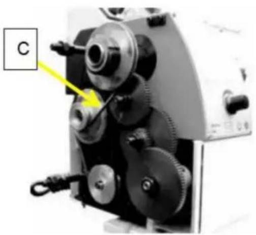
natural_image
Close-up of a mechanical device with gears and a labeled component 'C' (no readable text or symbols beyond label)Abb. 16Abb. 15
Manuelles Drehen
natural_image
Industrial lathe machine with visible control panel and mechanical components (no readable text or symbols)Abb. 17
natural_image
Industrial machine labeled WM210V with control panel and mechanical components (no readable text beyond label)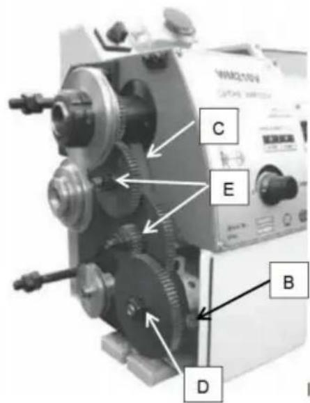
text_image
C E B D WQ210V CAPSAL SWITCHAbb. 19Abb. 18
text_image
Depth of Cut FeedFig. 21
text_image
La the Chuck flange 3 1 4 2 Workpiece Dept h of Cut Feed-
Fixed Centre 60°
-
Living Centre 60°
-
Dog Drive Pin
-
Dog Plate
Fig. 23
text_image
Labeled mechanical device diagram showing components A through E with annotations pointing to specific parts.Abb. 24
Gewindeschneiden
natural_image
Close-up of a mechanical tool component with a labeled 'E' and an arrow pointing to a circular feature (no readable text or symbols beyond the label)Abb. 26
natural_image
Close-up of a metallic industrial machine component (no visible text or symbols)Fig. 27
Bohrfutter (optional)
natural_image
Close-up of a mechanical assembly with a labeled component 'D' pointing to a cylindrical component (no visible text or symbols beyond label)Abb. 29
Lünette Die
natural_image
Close-up of a metalworking machine with a blue clamp and red base (no visible text or symbols)Abb. 31
ADJUSTMENTS
natural_image
Close-up of a mechanical lathe machine with visible gears and shafts (no text or symbols)Abb. 33
natural_image
Close-up of a mechanical assembly with labeled components (no readable text or symbols)Abb. 35
LUBR1CAT10N

CAUT10N
Lathe must be serviced at all lubrication points and all reservoirs filled to operating level before the lathe is placed into servicel
Failure to comply may cause serious damage
HINWEISE:
natural_image
Close-up of a mechanical gear assembly with visible gears and mounting base (no text or symbols)
natural_image
Close-up of a mechanical assembly with a threaded component and a labeled component 'D' (no readable text or symbols beyond label)Abb. 38Abb. 37
Strom
! WARNING!
text_image
Exploded view diagram of a mechanical assembly with numbered parts for identificationtext_image
Exploded view diagram of a mechanical assembly with numbered components and assembly detailstext_image
Exploded view diagram of a mechanical assembly with numbered parts for identificationtext_image
Technical diagram of mechanical gear assembly with numbered components and exploded viewtext_image
Exploded view diagram of a mechanical assembly with numbered parts for identificationC/O YH Consulting Limited, Büro 147, Centurion House, London Road, Staines-upon-Thames, Surrey, TW18 4AX
VEVOR®
TOUGH TOOLS, HALF PRICE
www.vevor.com/support
VEVOR®
TOUGH TOOLS, HALF PRICE
elettronica www.vevor.com/support
MANUALE D'USO DEL TORNIO PER METALLI
MODELLO:WM210V
natural_image
Industrial machine with warning label and control panel (no readable text or symbols)natural_image
Collection of mechanical tools and components including wrenches, screwdrivers, and a green base case (no text or symbols visible)Figura 1
natural_image
Industrial machine with metal components and a circular dial (no visible text or symbols)Figura 3
Testata (Fig. 4)
natural_image
Close-up of a mechanical lathe machine with no visible text or symbolsFigura 5
Grembiule (Fig. 6)
natural_image
Close-up of a mechanical assembly with a circular component and a metallic ring, no visible text or symbols.Figura 6
Vite di comando
natural_image
Close-up of a mechanical assembly with labeled components A and B (no readable text or symbols beyond labels)Figura 7
Contropunta (Fig. 8)
natural_image
Industrial machine with a large cylindrical component and a labeled section (C), no visible text or symbols on the machinery itself.Figura 8
Avviso:
natural_image
Close-up of a mechanical assembly with metallic components and a labeled component 'A' (no readable text or symbols)Figura 10Figura 9
4ÿBlocco carrello
natural_image
Industrial lathe machine with dual motors and a central shaft (no visible text or symbols)Figura 13 Figura 14
natural_image
Industrial machine with labeled component B, showing control panel and buttons (no readable text or symbols beyond label)
natural_image
Close-up of a mechanical device with gears and a labeled component 'C' (no readable text or symbols beyond label)Figura 16Figura 15
Tornitura manuale
natural_image
Industrial lathe machine with visible control panel and mechanical components (no readable text or symbols)Figura 17
natural_image
Industrial machine labeled WM210V with control panel and mechanical components (no readable text beyond label)
text_image
C E B D W8Q10V CAPSAL SWITCHFigura 19Figura 18
other
| | A | B | C | D | E | | ------ | --- | --- | --- | --- | --- | | 0.0037" | 55 | 53 | 71 | 60 | 53 | | 0.0068" | 60 | 57 | 72 | 63 | 55 | | | | | | | | | | | | | | | | | | | | | | | | | | | | | | | | | | | | | | | | | | | | | | | | | | | | | | | | | | | | | H | H | H | | | | | H | H | H | | | | | H | H | H | | | | | H | H | H | | | | | H | H | H | | | | | H | H | H | | | | | H | H | H | | = 0.40, 0.50, 0.60, 0.70, 0.80, 1.00, 1.25, 1.50, 1.75, 2.00, 2.50, 3.00, n/1" | | | A | B | C | D | E | | | | | | | | | | | | | | | | | | | | | | | | | | | | | | | | | | | | | | | | | | | | | | | | | | | | | | | | | | | | | H | H | H | | | | | H | H | H | | | | | H | H | H | | | | | H | H | H | | | | | H | H | H | | | | | H | H | H | | | | | H | H | H | | = 0.40, 0.50, 0.60, 0.70, 0.80, 1.00, 1.25, 1.50, 1.75, 2.00, 2.50, 3.00, n/1" | | | A | B | C | D | E | | | | | | | | | | | | | | | | | | | | | | | | | | | | | | | | | | | | | | | | | | | | | | | | | K/A | | = 0.40, 0.50, 0.60, 0.70, 0.80, 1.00, 1.25, 1.50, 1.75, 2.00, 2.50, 3.00, n/1" | | , , , , , , , , , , , , , , , , , , , , , , , , , , , , , , , N/A / VFigura 20
text_image
Depth of Cut FeedFig. 21
Caching e Ordini (Fig. 22)
text_image
La the Chuck flange 3 1 4 Workpiece ce Dept h of Cut Feed-
Fixed Centre 60°
-
Living Centre 60°
-
Dog Drive Pin
-
Dog Plate
Fig. 23
text_image
Labeled photograph of a lathe machine with numbered components A through EFigura 24
Taglio del filo
natural_image
Close-up of a mechanical tool component with a labeled 'E' and an arrow pointing to a circular feature (no readable text or symbols beyond the label)Figura 26
natural_image
Close-up of a metallic industrial machine component (no visible text or symbols)Fig. 27
natural_image
Close-up of a mechanical assembly with a labeled component 'D' and a tool, no readable text or symbols present.Figura 29
Lunetta fissa
natural_image
Close-up of a metalworking machine with a curved clamp and mounting base (no visible text or symbols)Figura 31
ADJUSTMENTS
natural_image
Industrial machine with mechanical components and a blue component (no visible text or symbols)Figura 33
natural_image
Mechanical assembly with labeled components (J, I) and no readable text or symbols beyond labelsFigura 35
LUBR1CAT10N

CAUT10N
Lathe must be serviced at all lubrication points and all reservoirs filled to operating level before the lathe is placed into servicel
Failure to comply may cause serious damage
NOTE:
natural_image
Close-up of a mechanical gear assembly with visible teeth and mounting base (no text or symbols)
natural_image
Close-up of a mechanical assembly with a threaded component and labeled part D (no readable text or symbols beyond label)Figura 38Figura 37
Elettricità

AVVERTIMENTO!
text_image
Exploded view diagram of a mechanical assembly with numbered parts for identificationtext_image
Exploded view diagram of a mechanical assembly with numbered components and assembly detailstext_image
Exploded view diagram of a mechanical assembly with numbered parts for identificationtext_image
Technical diagram of mechanical gear assembly with numbered components and exploded viewtext_image
Exploded view diagram of a mechanical assembly with numbered parts for identificationRancho Cucamonga, CA 91730
C/O YH Consulting Limited Ufficio 147, Centurion House,
Via Roma, 101, 00186 Roma, Italia
VEVOR®
TOUGH TOOLS, HALF PRICE
www.vevor.com/support
VEVOR®
TOUGH TOOLS, HALF PRICE
natural_image
Industrial machine with visible control panel and warning label (no readable text or symbols on the machine itself)natural_image
Collection of mechanical tools and components including wrenches, screwdrivers, and a green base case (no text or symbols visible)Figura 1
natural_image
Industrial machine with metal components and a circular dial (no visible text or symbols)Figura 3
Clavijero (Fig. 4)
natural_image
Close-up of a mechanical lathe machine with no visible text or symbolsFigura 5
Delantal (Fig. 6)
natural_image
Close-up of a mechanical assembly with a circular component and a metallic ring, no visible text or symbols.Figura 6
El husillo (A,
natural_image
Close-up of a mechanical assembly with labeled components A and B (no readable text or symbols beyond labels)Figura 7
natural_image
Industrial machine with a large cylindrical component mounted on a workbench, labeled 'C' (no visible text or symbols on the machine itself)Figura 8
Aviso:
natural_image
Close-up of a precision machine with labeled component A, showing mechanical components and no readable text or symbols.Figura 9 Figura 10
4 Bloqueo del carro
natural_image
Industrial lathe machine with visible gears and shafts (no text or symbols)Figura 13 Figura 14
natural_image
Industrial machine with labeled component B, showing control panel and buttons (no readable text or symbols beyond label)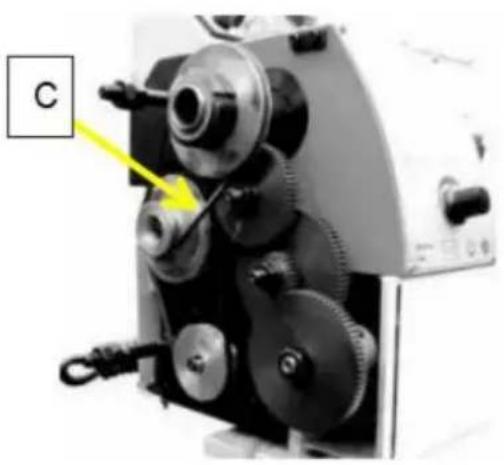
natural_image
Close-up of a mechanical device with gears and a labeled component 'C' (no readable text or symbols beyond label)Figura 16Figura 15
Torneado manual
natural_image
Industrial lathe machine with visible control panel and mechanical components (no readable text or symbols)Figura 17
natural_image
Industrial machine labeled WM210V with control panel and mechanical components (no readable text beyond label)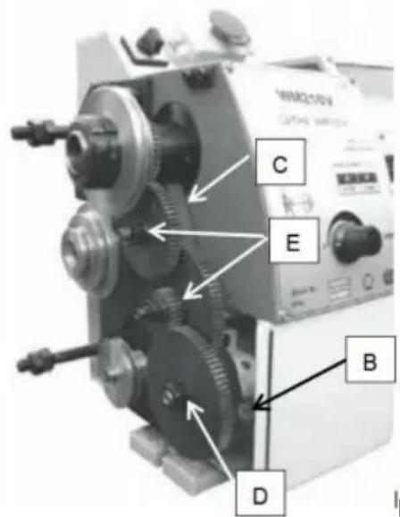
text_image
WAQ10V C E B DFigura 19Figura 18
text_image
Depth of Cut FeedFig. 21
text_image
La the Chuck flange 3 1 4 2 Workpiece Dept h of Cut Feed-
Fixed Centre 60°
-
Living Centre 60°
-
Dog Drive Pin
-
Dog Plate
Fig. 23
text_image
Labeled photograph of a lathe machine with numbered components A through EFigura 24
Corte de roscas
natural_image
Close-up of a mechanical tool component with a labeled 'E' and an arrow pointing to a circular feature (no readable text or symbols beyond the label)Figura 26
natural_image
Close-up of a metallic industrial machine component (no visible text or symbols)Fig. 27
natural_image
Close-up of a mechanical assembly with a labeled component 'D' pointing to a shaft (no visible text or symbols beyond label)Figura 29
Luneta. La luneta
natural_image
Industrial machine with metal clamp and mechanical components (no visible text or symbols)Figura 31
ADJUSTMENTS
natural_image
Industrial machine with mechanical components and a blue component (no visible text or symbols)Figura 33
text_image
Technical diagram of a mechanical assembly with labeled parts J and I, showing components like rollers and springs.Figura 35
LUBR1CAT10N

CAUT10N
Lathe must be serviced at all lubrication points and all reservoirs filled to operating level before the lathe is placed into servicel
Failure to comply may cause serious damage
NOTAS:
natural_image
Close-up of a mechanical gear assembly with visible teeth and mounting base (no text or symbols)Figura 37

natural_image
Close-up of a mechanical assembly with a threaded component and a labeled part 'D' (no readable text or symbols beyond label)Figura 38
Electricidad

ADVERTENCIA!
text_image
Exploded view diagram of a mechanical assembly with numbered parts for identification| RegionesNo. | Descripción | Especificación Cantidad | RegionesNo. | Descripción | Especificación Cantidad | ||
| 101 | Tornillo | M5x25 | 4 | 123 | Anillo de resorte | f22xl | |
| 102 Lavadora | 4 | 124 | Cubrir | ||||
| 103 Motor de CC | 83ZY005A | . | 125 | Tornillo | M8x25 | ||
| 104 | Extractor de motor | . | 126 | Arandela | 8 | ||
| 105 | Llave | A4x4x20 | . | 127 | Tuerca | M8 | |
| 106 | Tornillo | M6x8 | . | 128 | Arandela | 8 | |
| 107 | Cinturón | Puertas-5M-360 2 | 129 | Tornillo | M8 | ||
| 108 | Placa de soporte | . | 130 | Cubierta del cinturón | |||
| 109 Lavadora | 3 | 131 | Tuerca8 | MI0 | |||
| 110 Tornillo | Tornillo | M8x20 | 3 | 132 | MI0x80 | ||
| 111 | Bloquear | . | 133 | Tuerca | MI0 | ||
| 112 | Tornillo | M6x30 | . | 134 | Tuerca | M27xl | |
| 113 | Bloquear | . | 135 | Extractor de husillo | |||
| 114 | Tornillo | M6x20 | . | 136 | Engranaje | 40T | |
| 115 | Tomillo | . | 137 | Separador | |||
| 116 | Bloquear | . | 138 | Empaquetadora | |||
| 117 Lavadora | . | 139 | Cojinete | 30206 | |||
| 118 | Tuerca | . | 140 | Cubierta de grasa | |||
| 119 | Anillo de resorte | 8x0.8 | . | 141 | Tornillo M4xl0 | ||
| 120 | Tomillo | . | 142 | Bloquear | |||
| 121 | Cojinete | . | 143 | Clavijero | |||
| 122 | Polea | . | 144 | Llave | A3x3xl5 | ||
DIAGRAMA DE DESGLOSE Y LISTA DE PIEZAS
text_image
Exploded view diagram of a mechanical assembly with numbered components and assembly details| RegionesNo. | Descripción | Especificación | Cantidad | RegionesNo. | Descripción | Especificación Cantidad | |
| 201 | 1 | 228 | Tornillo | M4x8Manejar | |||
| Base de manija 202 | 1 | 229 | Tornillo | M5x10 | |||
| 203 | Arandela | 1 | 230 | Arbusto | |||
| 204 | Tomillo | 1 | 231 | Copa de aceite | F5 | ||
| 205 | Tornillo | M6x25 | 1 | 232 | Tornillo | M4x20 | |
| 206 | Alfiler | 1 | 233 | Gibratar | |||
| 207 | Primavera | 5x10x1 | 1 | 234 | Tornillo | ||
| 208 Diapositiva longitudinal y | 1 | 235 | Cubierta del limpiaparabrisas | ||||
| 209 | Tuerca | M4 | 9 | 236 | Limplaparabrisas | ||
| 210 | Tornillo | M4x14 | 3 | 237 | Gibratar | ||
| 211 | Gibratar | 1 | 238 | Tornillo | |||
| 212 | Descanso superior | 1 | 239 | Bloque deslizante | |||
| 213 | Tornillo | M5x30 | 1 | 240 | Tornillo | M4x10 | |
| Base giratoria 214 | M6x20 | 1 | 241 | Tuerca | |||
| Bandeja de 215 micrómetros | 1 | 242 | Tomillo de avance | ||||
| 216 | Tornillo de avance | 1 | 243 | Bloque de manija | |||
| 217 | Llave | 3x12 | 1 | 244 | Volante | ||
| 218 | Soporte | 1 | 245 | Cuello | |||
| 219 | Tornillo | M5x12 | 2 | 246 | Tornillo | M6x50 | |
| 220 | Cuello | 1 | 247 | Soporte | |||
| 221 | Tornillo | 2 | 248 | Placa de sujeción | |||
| 222 | Alfiler | 2 | 249 | Tornillo | |||
| 223 | Primavera | 2 | 250 | Bloque deslizante | |||
| 224 | Volante | 1 | 251 | Limplaparabrisas | |||
| Bloque de manija 225 | 1 | 252 | Cubierta del limpiaparabrisas | ||||
| 226 Manguito de manija | 2 | 253 | Gibratar | ||||
| 227 | Manejar | 2 | 254 | Diapositiva cruzada | |||
text_image
Exploded view diagram of a mechanical assembly with numbered parts for identification| RegionesNo. | Descripción | Especificación | Cantidad | RegionesNo. | Descripción | Especificación Cantidad | |
| 301 | Tornillo | M8x8 | 1 | 317 | Media nuez | ||
| 302 | Tuerca | M8 | 1 | 318 | Alfiler | 4x10 | |
| 303 | Volante | 1 | 319 | Tornillo | M4x10 | ||
| 304 | Primavera | 1 | 320 | Bloquear | |||
| 305 | Tornillo | M5x10 | 2 | 321 | Tornillo | M6x8 | |
| 306 | Cuello | 1 | 322 | Primavera | 0,6 x 3,5 x 12 1 | ||
| 307 | Soporte | 1 | 323 | Pelota | 4.5 | ||
| 308 | Tornillo | M8x25 | 2 | 324 | Tornillo | M4x12 | |
| 309 | Tornillo | M5x8 | 1 | 325 | Tuerca | M4 | |
| 310 | Delantal | 1 | 326 | Eje | |||
| 31 1 | Llave | A3x3x8 | 1 | 327 | Alfiler | 3x30 | |
| 312 | Eje de engranaje | 14T | 1 | 328 | Base de mano | ||
| 313 | Eje | 1 | 329 | Tornillo | M5X6 | ||
| 314 | Engranaje | 44/21T | 1 | 330 | Manejar | ||
| 315 | Tornillo | M4x35 | 1 | 331 | Manejar | ||
| 316 | Tuerca | M4 | 1 | 317 | Media nuez |
text_image
Technical diagram of mechanical gear assembly with numbered components and exploded viewtext_image
Exploded view diagram of a mechanical assembly with numbered parts for identificationRancho Cucamonga, CA 91730

text_image
Representante del CEE-CrossStu GmbH
C/O YH Consulting Limited Oficina 147, Centurion House,
London Road, Staines-upon-Thames, Surrey, TW18 4AX
VEVOR®
TOUGH TOOLS, HALF PRICE
www.vevor.com/support
VEVOR®
TOUGH TOOLS, HALF PRICE
natural_image
Industrial lathe machine with control panel and warning label (no readable text or symbols on the machine itself)natural_image
Collection of mechanical tools and components including wrenches, screwdrivers, and a green base case (no text or symbols visible)Rys. 1
natural_image
Industrial machine with metal components and a circular dial (no visible text or symbols)Rys. 3
Główka (rys. 4)
natural_image
Close-up of a mechanical lathe machine with no visible text or symbolsRys. 5
Fartuch (rys. 6)
natural_image
Close-up of a mechanical lathe machine with a circular component and a close-up inset showing a mechanical part (no visible text or symbols)Rys. 6
Machine Translated by Google
Śruba pociągowa
natural_image
Close-up of a mechanical cutting machine with labeled parts A and B (no readable text or symbols beyond labels)Ryc.7
Konik (rys. 8)
natural_image
Industrial machine with a large cylindrical component and a labeled section (C), no visible text or symbols on the machinery itself.Ryc.8
Ogłoszenie:
natural_image
Close-up of a precision optical instrument with metallic components and a labeled component 'A' (no readable text or symbols beyond label)Ryc.10Ryc.9
4 Blokada wózka
natural_image
Industrial lathe machine with visible gears and shafts (no text or symbols)Ryc. 14Ryc. 1
USTAWIENIE NARZĘDZIA
natural_image
Industrial machine with labeled component B, showing control panel and buttons (no readable text or symbols beyond label)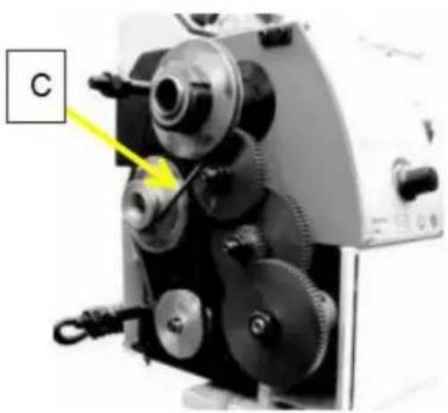
natural_image
Close-up of a mechanical device with gears and a labeled component 'C' (no readable text or symbols beyond label)Ryc. 16Ryc. 15
Toczenie ręczne
natural_image
Industrial lathe machine with visible control panel and spool (no text or symbols)Ryc. 17
natural_image
Industrial machine labeled WM210V with control panel and mechanical components (no readable text beyond label)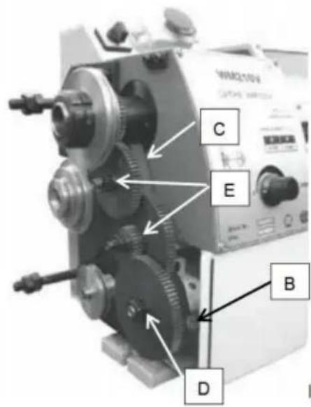
text_image
C E B D WAG10V GATALL SWITCHRyc. 19Ryc. 18
other
| | A | B | C | D | E | | ------ | --- | --- | --- | --- | --- | | A | 60 | H | 80 | 24 | 80 | | B | 72 | H | 52 | 40 | 80 | | C | 66 | H | 40 | 66 | 52 | | D | 60 | H | 40 | 60 | 52 | | E | 52 | H | 33 | 60 | 52 | | F | 52 | H | 33 | 60 | 52 | | mm | | | | | | | A | 60 | H | 80 | 24 | 80 | | B | 72 | H | 80 | 40 | 80 | | C | 66 | H | 80 | 40 | 80 | | D | 60 | H | 80 | 66 | 52 | | E | 52 | H | 80 | 40 | 52 | | F | 52 | H | 80 | 60 | 52 | | mm | | | | | | | A | | | | | | | B | | | | | | | C | | | | | | | D | | | | | | | E | | | | | | | F | | | | | | | mm | | | | | | | A | | | | | | | B | | | | | | | C | | | | | | | D | | | | | | | E | | | | | | | F | | | | | | | | mm | | | | | | | A | | | | | | | B | | | | | | | C | | | | | | | D | | | | | | | E | | | | | | | F | | | | | | | m | | | | | | | A | | H | | | | | B | | H | | | | | C | | H | | | | | D | | H | | | | | E | | H | | | | | m | | H | | | | | mm | (not labeled) for the top row; the bottom row is a separate table. The values in the table are estimated based on the 'mm' label in the first row. The 'n/1'' label is the bottom row.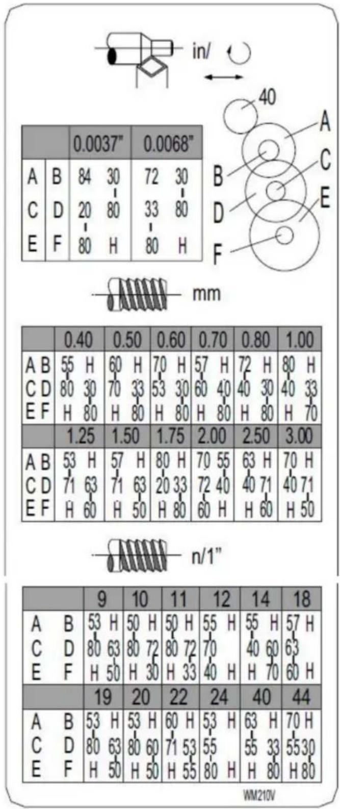
text_image
in/ A B 84 30 72 30 C D 20 80 33 80 E F 80 H 80 H mm 0.40 0.50 0.60 0.70 0.80 1.00 A B 55 H 60 H 70 H 57 H 72 H 80 H C D 80 30 70 33 53 30 60 40 40 30 40 33 E F H 80 H 80 H 80 H 80 H 80 H 70 1.25 1.50 1.75 2.00 2.50 3.00 A B 53 H 57 H 80 H 70 55 63 H 70 H C D 71 63 71 63 20 33 72 40 40 71 40 71 E F H 60 H 50 H 80 H 60 H H 60 H 50 n/1" 9 10 11 12 14 18 A B 53 H 50 H 50 H 55 H 55 H 57 H C D 80 63 80 72 80 72 70 E F H 50 H 30 H 33 H 19 20 22 24 40 44 A B 53 H 53 H 60 H 53 H 63 H 70 H C D 80 63 80 60 71 53 55 E F H 50 H 50 H 55 H WM210VRyc. 20
text_image
Depth of Cut FeedFig. 21
text_image
La the Chuck flange 3 1 4 2 Workpiece ce Dept h of Cut Feed-
Fixed Centre 60°
-
Living Centre 60°
-
Dog Drive Pin
-
Dog Plate
Fig. 23
text_image
Labeled mechanical device diagram showing components A through E with annotations pointing to specific parts.Ryc. 24
Ciecie gwintów
natural_image
Close-up of a metallic industrial machine component with a labeled 'E' and arrow indicator (no readable text or symbols beyond the label)Ryc. 26
natural_image
Close-up of a metallic industrial machine component (no visible text or symbols)Fig. 27
natural_image
Close-up of a mechanical assembly with a metallic component and labeled part D (no readable text or symbols)Ryc. 29
Podtrzymka
natural_image
Close-up of a metal clamp tool in operation, no visible text or symbolsRyc. 31
ADJUSTMENTS
natural_image
Industrial machine with mechanical components and a blue component (no visible text or symbols)Ryc. 33
text_image
Technical diagram of a mechanical assembly with labeled components J and I, showing internal components and connections.Ryc. 35
LUBR1CAT10N

CAUT10N
Lathe must be serviced at all lubrication points and all reservoirs filled to operating level before the lathe is placed into servicel
Failure to comply may cause serious damage
UWAGI:
natural_image
Close-up of a mechanical gear assembly with visible teeth and mounting base (no text or symbols)
natural_image
Close-up of a mechanical assembly with a threaded component and a labeled part 'D' (no readable text or symbols beyond label)Ryc. 38Ryc. 37
Elektryczność
OSTRZEŻENIE!
text_image
Exploded view diagram of a mechanical assembly with numbered parts for identificationtext_image
Exploded view diagram of a mechanical assembly with numbered components and assembly detailstext_image
Exploded view diagram of a mechanical assembly with numbered parts for identificationtext_image
Technical diagram of mechanical gear assembly with numbered components and exploded viewtext_image
Exploded view diagram of a mechanical assembly with numbered parts for identificationC/O YH Consulting Limited Biuro 147, Centurion House, London Road, Staines-upon-Thames, Surrey, TW18 4AX
VEVOR®
TOUGH TOOLS, HALF PRICE
www.vevor.com/support
VEVOR®
TOUGH TOOLS, HALF PRICE
Technische ondersteuning en e-garantiecertificaat www.vevor.com/support
METAALDRAAIBANK GEBRUIKERSHANDLEIDING
MODEL:WM210V
natural_image
Industrial lathe machine with control panel and warning label (no readable text or symbols on the machine itself)HULP NODIG? NEEM CONTACT MET ONS OP!
VEILIGHEIDSWAARSCHUWING
natural_image
Collection of mechanical tools and components including wrenches, screwdrivers, and a green base case (no text or symbols visible)Afbeelding 1
Accessoires in de gereedschapskist (Fig. 1)
natural_image
Industrial machine with dual gears and control panel (no visible text or symbols)Afbeelding 3
Kop (Fig. 4)
natural_image
Close-up of a mechanical lathe machine with no visible text or symbolsAfbeelding 5
Schort (Fig. 6)
natural_image
Close-up of a mechanical assembly with a circular component and a metallic ring, no visible text or symbols.Afbeelding 6
Leidingspindel
natural_image
Industrial machine with a large cylindrical component and a labeled section (C), no visible text or symbols on the machinery itself.Afbeelding 8
Kennisgeving:
natural_image
Close-up of a mechanical device with metallic components and a labeled component 'A' (no readable text or symbols beyond label)8yCompound Rest Traverse Hendel (E, Fig. 11)
natural_image
Industrial lathe machine with dual levers and workpiece (no visible text or symbols)natural_image
Industrial machine with labeled component B, showing control panel and buttons (no readable text or symbols beyond label)
natural_image
Close-up of a mechanical device with gears and a labeled component 'C' (no readable text or symbols beyond label)natural_image
Industrial lathe machine with visible control panel and mechanical components (no readable text or symbols)Afbeelding 17
natural_image
Industrial machine labeled WM210V with control panel and mechanical components (no readable text beyond label)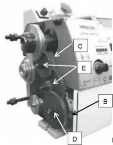
text_image
WM210V CAPITAL SWITCH C E B Dtext_image
Depth of Cut FeedFig. 21
Caching en Oecessen (Fig. 22)
text_image
La the Chuck flange 3 1 4 2 Workpiece Dept h of Cut Feed-
Fixed Centre 60°
-
Living Centre 60°
-
Dog Drive Pin
-
Dog Plate
Fig. 23
text_image
Labeled photograph of a lathe machine with numbered components A through EAfbeelding 24
Draadsnijden
natural_image
Close-up of a metallic industrial machine component with a labeled 'E' and arrow pointing to a circular feature (no readable text or symbols beyond the label)Afbeelding 26
natural_image
Close-up of a metallic industrial machine component (no visible text or symbols)Fig. 27
Boorkop (optioneel)
natural_image
Close-up of a mechanical assembly with a labeled component 'D' pointing to a shaft (no visible text or symbols beyond label)Afbeelding 29
Stevige rust De
natural_image
Close-up of a metalworking machine with a blue clamp and pink base (no visible text or symbols)Afbeelding 31
ADJUSTMENTS
natural_image
Industrial machine with mechanical components and a blue component (no visible text or symbols)Afbeelding 33
text_image
Technical diagram of a mechanical assembly with labeled components including J, I, and reference linesAfbeelding 35
LUBR1CAT10N

CAUT10N
Lathe must be serviced at all lubrication points and all reservoirs filled to operating level before the lathe is placed into servicel
Failure to comply may cause serious damage
OPMERKINGEN:
natural_image
Close-up of a mechanical gear assembly with visible teeth and mounting base (no text or symbols)Afbeelding 37

natural_image
Close-up of a mechanical assembly with a threaded component and a labeled part 'D' (no readable text or symbols beyond label)Afbeelding 38
Elektriciteit

WAARSCHUWING!
text_image
Exploded view diagram of a mechanical assembly with numbered parts for identificationtext_image
Exploded view diagram of a mechanical assembly with numbered components and assembly detailstext_image
Exploded view diagram of a mechanical assembly with numbered parts for identification| Nee. | Beschrijving | Specificatie | Hoewelheid | OnderdelenNee. | OnderdelenBeschrijving | Specificatie Hoeveelheid | |
| 301 | Schroef | M8x8 | 1 | 317 | Halve noot | ||
| 302 | Moer | M8 | 1 | 318 | Pin | 4x10 | |
| 303 | Handwiel | 1 | 319 | Schroef | M4x10 | ||
| 304 | Lente | 1 | 320 | Blok | |||
| 305 | Schroef | M5x10 | 2 | 321 | Schroef | M6x8 | |
| 306 | Kraag | 1 | 322 | Lente | 0,6x 3,5x12 1 | ||
| 307 | Beugel | 1 | 323 | Bal | 4.5 | ||
| 308 | Schroef | M8x25 | 2 | 324 | Schroef | M4x12 | |
| 309 | Schroef | M5x8 | 1 | 325 | Moer | M4 | |
| 310 | Schort | 1 | 326 | Schacht | |||
| 31 1 | Sleutel | A3x3x8 | 1 | 327 | Pin | 3x30 | |
| Tandwielas | 14T | 1 | 328312 | Handbasis | |||
| 313 | Schacht | 1 | 329 | Schroef | M5X6 | ||
| 314 | Versnelling | 44/21T | 1 | 330 | Hendel | ||
| 315 | Schroef | M4x35 | 1 | 331 | Hendel | ||
| 316 | Moer | M4 | 1 | 317 | Halve noot |
Bed, hangende wielonderdelen Montage
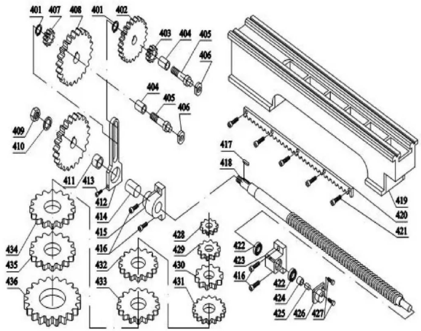
text_image
Technical diagram of mechanical gear assembly with numbered components and exploded viewtext_image
Exploded view diagram of a mechanical assembly with numbered parts for identificationC/O YH Consulting Limited Kantoor 147, Centurion House, Londen Road, Staines-upon-Thames, Surrey, TW18 4AX
VEVOR®
TOUGH TOOLS, HALF PRICE
Technische ondersteuning en e-garantiecertificaat www.vevor.com/support
VEVOR®
TOUGH TOOLS, HALF PRICE
www.vevor.com/support
METALL VARV ANVÄNDARHANDBOK
MODELL: WM210V
natural_image
Industrial machine with visible control panel and warning label (no readable text or symbols on the machine itself)natural_image
Collection of mechanical tools and components including wrenches, screwdrivers, and a green base case (no text or symbols visible)Fig. 1
natural_image
Industrial lathe machine with dual rollers and control panel (no visible text or symbols)Fig. 3
Headstock (Fig. 4)
natural_image
Close-up of a mechanical lathe machine with no visible text or symbolsFig. 5
Förkläde (bild 6)
natural_image
Close-up of a mechanical lathe machine with a circular component and a close-up inset showing a mechanical part (no visible text or symbols)Fig. 6
Ledningsskruv
natural_image
Close-up of a mechanical assembly with labeled components A and B, no readable text or symbols beyond labelsFig. 7
Bakdosa (fig. 8)
natural_image
Industrial machine with a large cylindrical component and a labeled panel (C), no visible text or symbols on the machinery itself.Fig. 8
Varsel:
natural_image
Close-up of a mechanical device with metallic components and a labeled component 'A' (no readable text or symbols beyond label)Fig. 10Fig. 9
4ÿVagnslås
natural_image
Industrial lathe machine with visible gears and shafts (no text or symbols)Fig. 14Fig. 1
UPPSTÄLLNING AV VERKTYG
natural_image
Industrial machine with labeled component B, showing control panel and buttons (no readable text or symbols beyond label)
natural_image
Close-up of a mechanical device with gears and a labeled component 'C' (no readable text or symbols beyond label)Fig. 16Fig. 15
Manuell svarvning
natural_image
Industrial lathe machine with visible control panel and mechanical components (no readable text or symbols)Fig. 17
natural_image
Industrial machine labeled WM210V with control panel and mechanical components (no readable text beyond label)
text_image
C E B D WAG10V GATALL SWITCHFig. 19Fig. 18
Byt växlar
text_image
Depth of Cut FeedFig. 21
text_image
La the Chuck flange 3 1 4 2 Workpiece Dept h of Cut Feed-
Fixed Centre 60°
-
Living Centre 60°
-
Dog Drive Pin
-
Dog Plate
Fig. 23
text_image
Labeled mechanical device diagram showing components A through E with annotations pointing to specific parts.Fig. 24
Trådklippning
natural_image
Close-up of a mechanical tool component with a labeled 'E' and an arrow pointing to a circular feature (no readable text or symbols beyond the label)Fig. 26
natural_image
Close-up of a metallic industrial machine component (no visible text or symbols)Fig. 27
Borrchuck (tillval)
natural_image
Close-up of a mechanical assembly with a labeled component 'D' pointing to a shaft (no visible text or symbols)Fig. 29
Stadigt stöd
natural_image
Close-up of a metalworking machine with a blue clamp and red base (no visible text or symbols)Fig. 31
ADJUSTMENTS
natural_image
Close-up of a mechanical lathe machine with visible gears and shafts (no text or symbols)Fig. 33
natural_image
Close-up of a mechanical assembly with labeled components (no readable text or symbols)Fig. 35
LUBR1CAT10N

CAUT10N
Lathe must be serviced at all lubrication points and all reservoirs filled to operating level before the lathe is placed into servicel
Failure to comply may cause serious damage
ANMÄRKNINGAR:
natural_image
Close-up of a mechanical gear assembly with visible teeth and mounting base (no text or symbols)
natural_image
Close-up of a mechanical assembly with a threaded component and labeled point D (no text or symbols beyond label)Fig. 38Fig. 37
Elektricitet
! WARNING!
text_image
Exploded view diagram of a mechanical assembly with numbered parts for identification| Delar Inga. | Beskrivning | specifikation Antal | Delar Inga. | Beskrivning | specifikation Antal | ||
| 101 | Skruva | M5x25 | 4 | 123 | Spring Ring | f 22xl | |
| 102 | Bricka | 4 | 124 | Täcka | |||
| 103 | DC-motor | 83ZY005A | I | 125 | Skruva | M8x25 | |
| 104 | Motor avdragare | I | 126 | Bricka | 8 | ||
| 105 | Nyckel | A4x4x20 | I | 127 | Mutter | M8 | |
| 106 | Skruva | M6x8 | I | 128 | Bricka | 8 | |
| 107 | Bälte | Gates-5M- 360 2 | 129 | Skruva | M8 | ||
| 108 | Fästplatta | I | 130 | Bältesskydd | |||
| 109 | Bricka | 8 | 3 | 131 | Mutter | MIO | |
| 110 | Skruva | M8x20 | 3 | 132 | Bult | M10x80 | |
| 111 | Blockera | I | 133 | Mutter | MIO | ||
| 112 | Skruva | M6x30 | I | 134 | Mutter | M27xl | |
| 113 | Blockera | I | 135 | Spindeldragare | |||
| 114 | Skruva | M6x20 | I | 136 | Redskap | 40T | |
| 115 | Bult | I | 137 | Separator | |||
| 116 | Blockera | I | 138 | Packning | |||
| 117 | Bricka | I | 139 | Lager | 30206 | ||
| 118 | Mutter | I | 140 | Fettskydd | |||
| 119 | Spring Ring | ÿ8x0,8 | I | 141 | Skruva | M4xl0 | |
| 120 | Bult | I | 142 | Blockera | |||
| 121 | Lager | I | 143 | Headstock | |||
| 122 | Remskiva | I | 144 | Nyckel | A3x3xl5 |
UPPDELNINGSDIAGRAM OCH DELLISTA
text_image
Exploded view diagram of a mechanical assembly with numbered components and assembly details| Delar Inga. | Beskrivning | Specifikation | Antal | Delar Inga. | Beskrivning | Specifikation Antal | ||
| Hantera | 1 | 228 | Skruva201 | M4x8 | 1 | |||
| 202 Handtagsbas | 1 | 229 | Skruva | M5x10 | 1 | |||
| 203 | Bricka | 1 | 230 | Buske | 1 | |||
| 204 | Bult | 1 | 231 | oljekopp | F5 | 2 | ||
| 205 | Skruva | M6x25 | 1 | 232 | Skruva | M4x20 | 3 | |
| 206 | Stift | 1 | 233 | Gib | 1 | |||
| 207 | Fjädra | 5x10x1 | 1 | 234 | Skruva | 8 | ||
| 208 Långsgående glid ccn | 1 | 235 | Torkarskydd | 2 | ||||
| 209 | Mutter | M4 | 9 | 236 | Torkare | 2 | ||
| 210 | Skruva | M4x14 | 3 | 237 | Gib | 1 | ||
| 211 | Gib | 1 | 238 | Skruva | 6 | |||
| 212 | Top Rest | 1 | 239 | Glidblock | 1 | |||
| 213 | Skruva | M5x30 | 1 | 240 | M4x10Skruva | 6 | ||
| 214 Vridbas | M6x20 | 1 | 241 | Mutter | 1 | |||
| 215 mikrometer panna | 1 | 242 | Blyskruv | 1 | ||||
| 216 | Blyskruv | 1 | 243 | Handtagsblock | 1 | |||
| 217 | Nyckel | 3x12 | 1 | 244 | Handtag | 1 | ||
| 218 | Konsol | 1 | 245 | Krage | 1 | |||
| 219 | Skruva | M5x12 | 2 | 246 | Skruva | M6x50 | 2 | |
| 220 | Krage | 1 | 247 | Konsol | 1 | |||
| 221 | Skruva | 2 | 248 | Spännplatta | 1 | |||
| 222 | Stift | 2 | 249 | Skruva | 1 | |||
| 223 | Fjädra | 2 | 250 | Glidblock | 1 | |||
| 224 | Ratt | 1 | 251 | Torkare | 2 | |||
| 225 Handtagsblock | 1 | 252 | Torkarskydd | 2 | ||||
| 226 Handtagshylsa | 2 | 253 | Gib | 1 | ||||
| 227 | Hantera | 2 | 254 | Cross Slide | 1 | |||
Förkläde montering

text_image
Exploded view diagram of a mechanical assembly with numbered parts for identification| Inga. | Beskrivning | Specifikation | Antal | DelarDelar Inga. | Beskrivning | Specifikation Antal | |
| 301 | Skruva | M8x8 | 1 | 317 | Halvnöt | ||
| 302 | Mutter | M8 | 1 | 318 | Stift | ∅ 4x10 | |
| 303 | Ratt | 1 | 319 | Skruva | M4x10 | ||
| 304 | Fjädra | 1 | 320 | Blockera | |||
| 305 | Skruva | M5x10 | 2 | 321 | Skruva | M6x8 | |
| 306 | Krage | 1 | 322 | Fjädra | 0,6x3,5x12 1 | ||
| 307 | Konsol | 1 | 323 | Boll | ∅ 4.5 | ||
| 308 | Skruva | M8x25 | 2 | 324 | Skruva | M4x12 | |
| 309 | Skruva | M5x8 | 1 | 325 | Mutter | M4 | |
| 310 | Förkläde | 1 | 326 | Axel | |||
| 31 1 | Nyckel | A3x3x8 | 1 | 327 | Stift | ∅3x30 | |
| 312 | Kugghjulsaxel | 14T | 1 | 328 | Handbas | ||
| 313 | Axel | 1 | 329 | Skruva | M5X6 | ||
| 314 | Redskap | 44/21T | 1 | 330 | Hantera | ||
| 315 | Skruva | M4x35 | 1 | 331 | Hantera | ||
| 316 | Mutter | M4 | 1 | 317 | Halvnöt |
Säng, hängande hjuldelar Montering

text_image
Technical diagram of mechanical gear assembly with numbered components and exploded view| Delar Inga. | Beskrivning | Specifikation Antal | Delar Inga. | Beskrivning | Specifikation Antal | ||
| 401 | Spring Ring | 2 | 419 | Sång | |||
| 402 | Redskap | 60T | 1 | 420 | Kuggstång | ||
| 403 | Redskap | 20T | 1 | 421 | Skruva | M2x12 | |
| 404 | Buske | 1 | 422 | Lager | 51100 | ||
| 405 | Bolt | 1 | 423 | Rätt stöd | |||
| 406 | Mutter | M8 | 1 | 424 | Mutter | ||
| 407 | Redskap | 24T | 1 | 425 | Skruva | M8x6 | |
| 408 | Redskap | 80T | 1 | 426 | Täcka | ||
| 409 | Mutter | M10 | 1 | 427 | Skruva | M4x12 | |
| 410 | Bricka | 10 | 1 | 428 | Redskap | 25T | |
| 411 | Buske | 1 | 429 | Redskap | 30T | ||
| 412 | Ram | 1 | 430 | Redskap | 33T | ||
| 413 | Skruva | M6x35 | 1 | 431 | Redskap | 35T | |
| 414 | Buske | 1 | 432 | Redskap | 40T | ||
| 415 Vånsterstöd | 1 | 433 | Redskap | 45T | |||
| 416 | Skruva | M6x14 | 2 | 434 | Redskap | 50T | |
| 417 | Nyckel | A3x3x16 | 1 | 435 | Redskap | 52T | |
| 418 | Blyskruv | 1 | 436 | Redskap | 66T | ||
tailstock montering
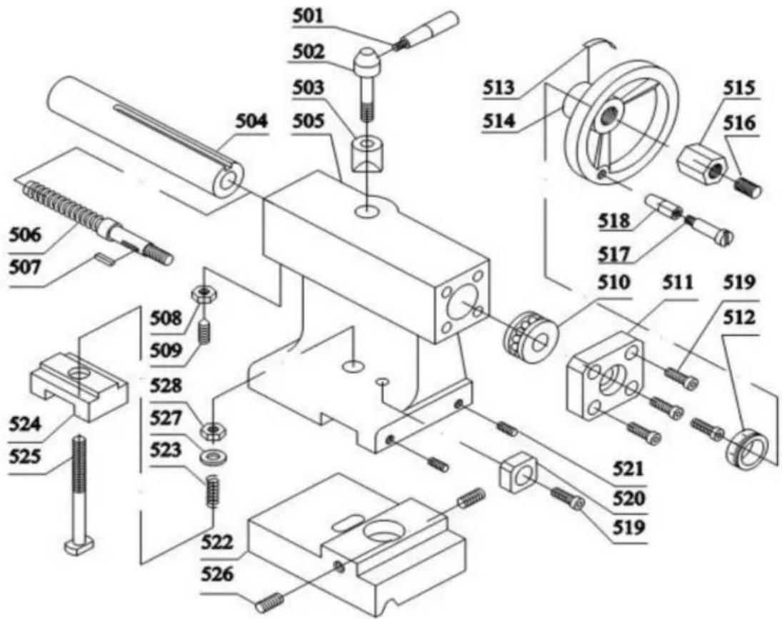
text_image
Exploded view diagram of a mechanical assembly with numbered parts for identification| Delar Inga. | Beskrivning | Specifikation Antal | Delar Inga. | Beskrivning | Specifikation Antal | |||
| 501 | Hantera | 1 | 515 | Mutter | M8 | 1 | ||
| 502 | Handtagsbas | 1 | 516 | Skruva | M8x6 | 1 | ||
| 503 | Låsbas | 1 | 517 | Handtag Skruv | 1 | |||
| 504 | Ärm | 1 | 518 | Handtagshylsa | 1 | |||
| 505 | Stjärtstock | 1 | 519 | Skruva | M5x12 | 1 | ||
| 506 | Blyskruv | 1 | 520 Justeringsblock | 1 | ||||
| 507 | Nyckel | A3x3x8 | 1 | 521 | Skruva | M6x12 | 1 | |
| 508 | Mutter | M6 | 1 | 522 | Bas | 1 | ||
| 509 | Skruva | M6x14 | 1 | 523 | Fjädra | 1 | ||
| 510 | Lager | 51100 | 1 | 524 | Spännplatta | 1 | ||
| 511 | Hus | 1 | 525 | Bult | M10x70 | 1 | ||
| 512 | Krage 526 | 1 | Skruva | M6x16 | 2 | |||
| 513 | Fjädra | 1 | 527 | tvättmaskin | ∅ 10 | 1 | ||
| 514 | Ratt | 1 | 528 | Mutter | M10 | 1 | ||
Tillverkare: Shanghaimuxinmuyeyouxiangongsi
Adress: Shuangchenglu 803nong11hao1602A-1609shi, Baoshanqu, Shanghai 200000 CN.
Importerad till USA: Sanven Technology Ltd., Suite 250, 9166 Anaheim Place, Rancho Cucamonga, CA 91730
| EC | REP |
E-CrossStu GmbH
Mainzer Landstr.69, 60329 Frankfurt am Main.
| UK | REP |
YH CONSULTING LIMITED.
C/O YH Consulting Limited Office 147, Centurion House, London Road, Staines-upon-Thames, Surrey, TW18 4AX
VEVOR®
TOUGH TOOLS, HALF PRICE
www.vevor.com/support