KEX-15 - Water pump Vevor - Free user manual and instructions
Find the device manual for free KEX-15 Vevor in PDF.


User questions about KEX-15 Vevor
0 question about this device. Answer the ones you know or ask your own.
Ask a new question about this device
Download the instructions for your Water pump in PDF format for free! Find your manual KEX-15 - Vevor and take your electronic device back in hand. On this page are published all the documents necessary for the use of your device. KEX-15 by Vevor.
USER MANUAL KEX-15 Vevor
Technical Support and E-Warranty Certificate www.vevor.com/support
DC FUEL TRANSFER PUMP
MODEL: KEX-15
We continue to be committed to provide you tools with competitive price. "Save Half", "Half Price" or any other similar expressions used by us only represent the estimate of savings you might benefit from buying certain tools with us compared to top brands and does not necessarily mean to cover all categories of tools offered. Are kindly reminded to verify carefully when you are placing an order with us actually saving half in comparison with the top major brands.
MODEL: KEX-15
NEED HELP? CONTACT US!
Have product questions? Need technical support? Please feel fr contact us:
Technical Support and E-Warranty Certificate www.vevor.com/support
This is the original instruction, please read all manual instruction carefully before operating. VEVOR reserves a clear interpretation user manual. The appearance of the product shall be subject to product you received. Please forgive us that we won't inform you there are any technology or software updates on our product.
| Warning-To reduce the risk of injury, user must read instructions manual carefully. | |
| This product is subject to the provision of European D 2012/19/EC. The symbol showing a wheelie bin crossed through indicates that the product requires separate refu collection in the European Union. This applies to the p and all accessories marked with this symbol. Products as such may not be discarded with normal domestic w must be taken to a collection point for recycling electri electronic devices |
MAIN SPECIFICATIONS
Application: Designed to safely transfer low viscosity petroleum fuels such gasoline (up to 15% alcohol blends such as E15), diesel fuel (up to 100 biodiesel such as B100) and kerosene. Pump is designed for permanent mounting on vented storage tanks.
Pump Housing: Lightweight, corrosion-resistant, cast aluminum body, convenient union ring for easy installation.
| Model | KEX-15 |
| Voltage | DC12V |
| Power | 1/5 HP |
| Max Flow | 15 GPM |
| Max lift | 33 FT |
| Max Suction lift | 8 FT |
| Applicable temperature | -25~50℃ |
| Working hours | Work for 30 minutes, stop for minute (at room temperature). |
Part List
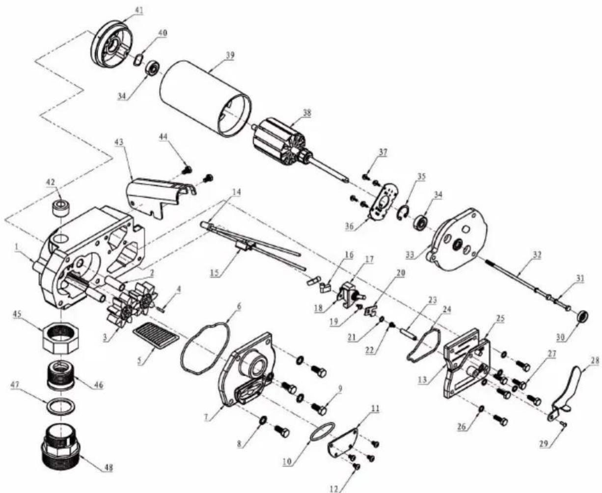
| No. | Description | Material | Quantity |
| 1 | Pump Body | Aluminum | 1 |
| 2 | Hollow Shaft | Gcr15 | 2 |
| 3 | Rotor | Reinforced Nylon | 2 |
| 4 | Flat Key | Carbon Steel | 1 |
| 5 | Filter | 304 Stainless Steel | 1 |
| 6 | O-Ring Outer Diameterφ92*2.65 | Gasoline-Resistant Nitrile Rubb | 1 |
| 7 | Cavity Cover | Aluminum | 1 |
| 8 | Internal Tooth Backstop Gasket | Carbon Steel | 4 |
| 9 | External Hexagonal Screw M8*20 | Carbon Steel | 4 |
| 10 | O-Ring Outer Diameterφ92*2.65 | Gasoline-Resistant Nitrile Rubb | 1 |
| 11 | Filter Cover | Q235A | 1 |
| 12 | Phillips Pan Head Screw M5*8 | Carbon Steel | 4 |
| 13 | Circuit Cover | Aluminum | 1 |
| 14 | Thermostat | 1 | |
| 15 | Strip-Free Quick Wiring Clamp | 1 | |
| 16 | Nylon Flag Type Terminal Block | 2 | |
| 17 | Second Gear Toggle Switch | 1 | |
| 18 | Switch Positioning Bracket | Q235A | 1 |
| 19 | Phillips Pan Head Screw M4*6 | Carbon Steel | 1 |
| 20 | Switch Stroke Card | Q235A | 1 |
| 21 | O-Ring Outer Diameter 9*2.5 | Gasoline-Resistant Nitrile Rubb | 1 |
| 22 | Cross Round Head Three Combination M3*6 | 304 Stainless Steel | 1 |
| 23 | Switch Bracket Connecting Rod | Q235A | 1 |
| 24 | O-Ring Outer Diameter 63*2.5 | Gasoline-Resistant Nitrile Rubb | 1 |
| 25 | Switch Cover | Aluminum | 1 |
| 26 | Internal Tooth Backstop Washer | Carbon Steel | 1 |
| 27 | External Hexagonal Screw M6*20 | Carbon Steel | 1 |
| 28 | Motor Switch Bracket | Q235A | 1 |
| 29 | Phillips Pan Head Screw M4*8 | 304 Stainless Steel | 1 |
| 30 | Skeleton Oil Seal 20*8*7 | Fluorine Rubber | 1 |
| 31 | External Hexagonal Screw M5*14 | 304 Stainless Steel | 2 |
| 32 | Spring Pad M5 | 304 Stainless Steel | 2 |
| 33 | Motor Cover | Aluminum | 1 |
| 34 | Deep Groove Ball Bearing 608-2 | Bearing Steel | 2 |
| 35 | Retaining Ring For Hole Φ22 | 65Mn | 1 |
| 36 | Carbon Brush Holder | 1 | |
| 37 | Phillips Pan Head Screw M3*8 | 304 Stainless Steel | 4 |
| 38 | Motor Rotor | 1 | |
| 39 | Motor Barrel | 1 | |
| 40 | Wave Pad 16*21*0.3 | 65Mn | 1 |
| 41 | Motor Bottom Cover | Aluminum | 1 |
| 42 | Hex Socket Plug 3/4 " | 304 Stainless Steel | 1 |
| 43 | Switch Limit Bracket | Q235A | 1 |
| 44 | External Hexagonal Screw M6*10 | Carbon Steel | 2 |
| 45 | Hexagonal Activity Hat | Q235A | 1 |
| 46 | Core Filling | Q235A | 1 |
| 47 | Flat Washers | Ptfe | 1 |
| 48 | Adjustable Joints | Cast Aluminum | 1 |
GENERALINFORMATION
The purpose of this manual is to assist you in installing, operating and maintaining your pump. This manual covers the 12-Volt DC electric gear pump KEX-15 Connect this pump to a 12-volt DC power source.
Do not attempt connection of any pump to a 115-volt AC or 230-volt AC pc source.

WARNING
This product shall not be used for pumping fuel or other liquids into aircraft.
An automatic bypass valve prevents pressure build up when the pump is on the nozzle closed. To avoid damage, do not run the pump more than 10 m with the nozzle closed.
The duty cycle of this pump is 30 minutes ON and 30 minutes OFF. Allow pump to cool for 30 minutes.
This pump is designed for use with gasoline (up to 15% alcohol blends such as E15), diesel fuel (up to 100% biodiesel such as B100) and kerosene. Do not do this pump for dispensing any fluids other than those for which it was designed to do so may damage pump components.
CAUTION
This pump has a minimum operating temperature of +40^ when used with E (biodiesel).
This pump is designed to operate on a typical DC automotive electrical syste. The pump is designed to operate with the appropriate DC voltage at the mo leads and the ratings are determined at this voltage.
Performance may vary due to length of power cord, battery condition or outp from the vehicle charging system that will affect system voltage.
Do not leave the system running with fluids. "Dry running" can damage the | Do not pump the tank completely dry, as contaminants from the bottom of the may enter the pump.
SAFETYINSTRUCTION

The following safety alert symbols are used in this manual.

DANGER
DANGER indicates a hazardous situation which,
if not avoided, will result in death or serious injury.

WARNING
WARNING indicates a hazardous situation
which, if not avoided, could result in death or serious injury.

CAUTION
CAUTION indicates a hazardous situation
which, if not avoided, may result in minor or moderate injury.
It is your responsibility to:
- know and follow applicable national, state, and local safety codes pertaining installing and operating electrical equipment for use with flammable liquids.
- know and follow all safety precautions when handling petroleum fuels.
-
- insure that all equipment operators have access to adequate instructions concerning safe operating and maintenance procedures.
Observe all safety precautions concerning safe handling of petroleum fuels. To ensure safe operation, all fuel transfer systems must be properly grounded. Proper grounding means a continuous metal-to-metal contact from one component to the next, including tank, bung, pump, meter, filter, hose and no Care should be taken to ensure proper grounding during initial installation and after any service or repair procedures.
For your safety, please take a moment to review the warnings below.
To prevent physical injury, observe precautions against fire or explosion when dispensing fuel.
Do not operate the system in the presence of any source of ignition including running or hot engines, lighted cigarettes, or gas or electric heaters.
Observe precautions against electrical shock when operating
To prevent physical injury, observe precautions against fire or explosion when dispensing fuel.
Do not operate the system in the presence of any source of ignition including running or hot engines, lighted cigarettes, or gas or electric heaters.
Observe precautions against electrical shock when operating the system. Serious or fatal shock can result from operating electrical equipment in damp or wet locations.
Inspect external pump wiring regularly to make sure it is correctly attached to battery.
To avoid electrical shock, use extra care when connecting the pump to power. Avoid prolonged skin contact with petroleum fuels. Use protective goggles, glo and aprons in case of splashing or spills.
Change saturated clothing and wash skin promptly with soap and water.
Observe precautions against electrical shock when servicing the pump.
Always disconnect power before repairing or servicing.
Never apply electrical power to the system when any of the cover plates are removed.
If using solvent to clean pump components or tank, observe the solvent manufacturer's recommendations for safe use and disposal.
INSTALLATION
This pump is designed to self-prime with dry gears.
Expect suction lift as follows:
Manual Nozzle: 5.5 feet (1.7 m) with diesel 6.7 feet (2.1 m) with gasoline
Automatic Nozzle: 4.8 feet (1.5 m) with diesel 5.8 feet (1.8 m) with gasoline
If you require a greater initial prime height, coat the gears with fluid by rem the plug on the top of the pump and pour a small quantity of motor oil int cavity. Replace the plug and try again.
A foot valve with pressure relief may be needed to maintain prime.
Make sure all threaded fuel connections are wrapped with three to four turns thread tape or a pipe thread sealant approved for use with petroleum fuels.
Install Bung Adapter and Suction Pipe
- Tighten the bung adapter snugly into the fuel tank.
- Place the union ring gasket into the inlet fitting on the bottom of the pum
- Thread the suction pipe into the inlet fitting and tighten until snug.
Install Pump on Tank
- Clean the tank interior of all dirt and foreign material.
- Extend the suction pipe to its full length and insert into the tank opening. 1)
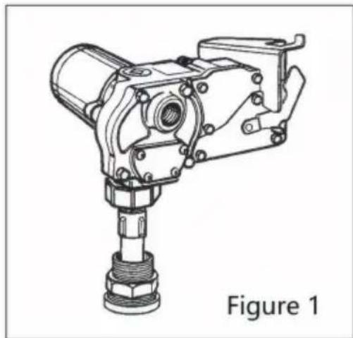
The suction pipe will adjust to the length needed to rest on the tank bottom.
- Place the pump on the bung adapter and tighten the union ring securely ' pipe wrench.
Make sure the union ring is not cross-threaded.
- To prevent pressure buildup and possible fuel leaks through the nozzle, measure the tank is vented.
A vent cap rated at 3 psi or less is recommended.
Install Electrical Connections
A grounding connection is provided. It is identified as a green colored binding screw in the electrical cavity.
The KEX-15 must be connected to a 12-volt DC power source.
Do not attempt connection of any pump to a 115-volt AC or 230-volt AC pc source.
For installation in unclassified areas, the supplied power cord, fuse and strain grip may be used.
To install the power cord, remove the electrical cover plate. (Figure 2)
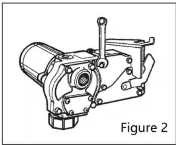
If necessary, trim the power cord to the desired length. Strip 3 to 4 inches (10 cm) of outer insulation from the power cord end. Then strip 1/2 inch (1.3 insulation from the power cord wires.
Slide the strain relief grip onto the power cord so that the threaded end of strain relief grip faces the tripped power wires. (Figure 3)
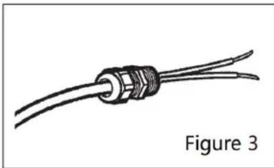
Insert the power cord through the 1/2 inch NPT connection on the back of pump. (Figure 4) Using wire nuts, connect the lack wire to the black wire a red wire to the red in the pumps electrical cavity. Position the wires inside the electrical cavity and tighten the strain relief grip securely. Make sure surfaces clean. Install
the cover plate and tighten securely.
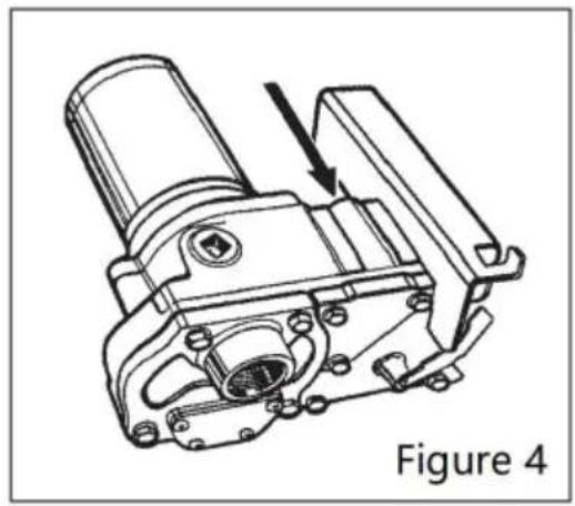
WARNING
Carefully route the power cord to the battery, protecting the power cord hot surfaces, sharp edges or anything that could damage the power cord resulting in a short circuit.
A fuse is provided to protect the power cord and motor. Install fuse in red wire of the power cord as close as possible to the battery.
Connect the red wire of the fuse to the positive (ungrounded) side of b Connect black wire to the negative (grounded) side of the battery.
Failure to follow these instructions could result in death, serious injury or loss of equipment due to short circuit, fire or explosion.
DANGER
If the pump is to be installed in a Hazardous (Classified) location, it must be installed by a licensed electrician and conform to National Fire Protection Association (NFPA) codes 30 and 70.
You as the owner, are responsible for seeing that the installation and operation of your pump complies with NFPA codes as well as any appli state and local codes.
Rigid conduit must be used to install wiring.
Note that the lead wires are factory-sealed isolating the motor from the junction box.
Failure to follow these wiring instructions may result in death or serious injury from shock, fire or explosion.
Install Hose and Nozzle
After sealing the threads, tighten the hose into the pump outlet and the nozzle on the hose.
The nozzle can be placed in the nozzle holder only when the pump is The nozzle holder allows the pump to be locked when the nozzle is in
OPERATION INSTRUCTIONS
ALWAYS FOLLOW SAFETY PRECAUTIONS WHEN OPERATING THIS EQUIPMENT. REVIEW THE SAFETY INSTRUCTIONS.
Before each use, repair leaks around seals or connections. Make sure hoses in good condition and connections are tight. Make sure the work area is dry. MAKE SURE THE PUMP IS PROPERLY GROUNDED.
Repair any corroded or damaged wiring before use. Ensure the tank contains enough fuel. Make sure the fuel is not contaminated with debris.
CAUTION
This pump is designed for use only with gasoline (up to 15% alcohol but such as E15), diesel fuel (up to 100% biodiesel such as B100) and kerosene. Do not use this pump for dispensing any fluids other than those for which was designed. To do so may damage pump components. This pump has minimum operating temperature of +40^ when used with B100 (biodiesel). Dispense Fuel
Turn the pump on by removing the nozzle from its holder and pushing up to switch lever. Insert the nozzle into the receiving tank and squeeze the handle start fuel flow. When done, release the nozzle handle, turn the pump off, and return the nozzle to its holder.
This pump is designed to be self-priming. If fuel is not delivered within 15 t seconds, turn the pump off and
refer to the priming information in the Troubleshooting Section.
An automatic bypass valve prevents pressure buildup when the pump is on with the nozzle closed. To avoid
pump damage, do not run the pump for more than 10 minutes with the nozzle closed.
Motor Protector
The pump contains a motor protector that provides added protection against r damage. It must be reset manually.
If the motor protector trips, reset by turning the switch OFF. Let the pump turn ON again. If the motor protector trips again, see the Troubleshooting Set of this manual.
MAINTENANCE
This pump is designed for minimum maintenance. Motor bearings are sealed require no lubrication. Inspect the pump and components regularly for fuel lea and make sure the hose and power cord are in good condition. Keep the p exterior clean to help identify leaks.
Do not use this pump for water, chemicals, or herbicides. Dispensing any fluid other than those listed in this manual will damage the pump. Use of the pump unauthorized fluids.
To Clean or Replace Strainer
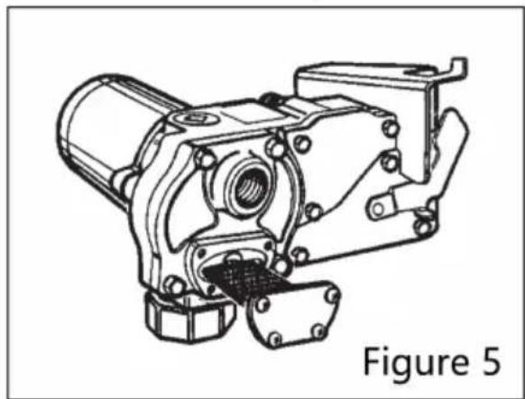
Turn the pump off and disconnect from power. Remove the strainer cover plate (Figure 5) Remove the inlet strainer and inspect for damage or clogs. Clean strainer with a soft-bristled brush and solvent. If the strainer is very dirty, compressed air may be used. If damaged, replace the strainer.
Place the strainer in the cavity. Clean the cover plate and O-ring. Coat the lightly with grease. Ensure the Cover plate O-ring is properly seated and tight the strainer cover plate.
REPAIR
Carefully inspect all parts for wear or damage. Replace components, as nee: The Illustrated Parts List gives information on replacement parts and kits. Review the Safety Instructions before proceeding.
WARNING
Observe precautions against electrical shock when servicing the pump. Always disconnect power before repairing or servicing. Never apply electrical power to the system when any of the cover plates are remove
CAUTION
Avoid prolonged skin contact with petroleum fuels. Use protective goggles, gloves and aprons in case of splashing or spills. Change saturated cloth and wash skin promptly with soap and water.
Remove Pump from Tank
- Turn the pump OFF and disconnect from power.
- Turn the union ring counterclockwise to release the inlet fitting.
- Lift the pump and suction pipe straight up from the bung adapter.
- Elevate the nozzle and hose to allow excess fuel to drain into the tank.
- Wipe the entire system with a clean cloth.
Service O-Rings
A Wet Seal Kit contains all seals for your pump and should be on hand w performing repairs. Old seals may then be replaced with new seals. In general, when inspecting O-rings, look for breaks, wear, and signs of deterioration, such as swelling. Replace, as necessary. Before seating, coat O-rings with light grease.
Replace Gears and Drive Key
- Turn the pump OFF and disconnect from power.
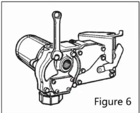
- Remove the gear cover plate. (Figure 6)
- Lift the drive key and gears from the pump. (Figure 7)
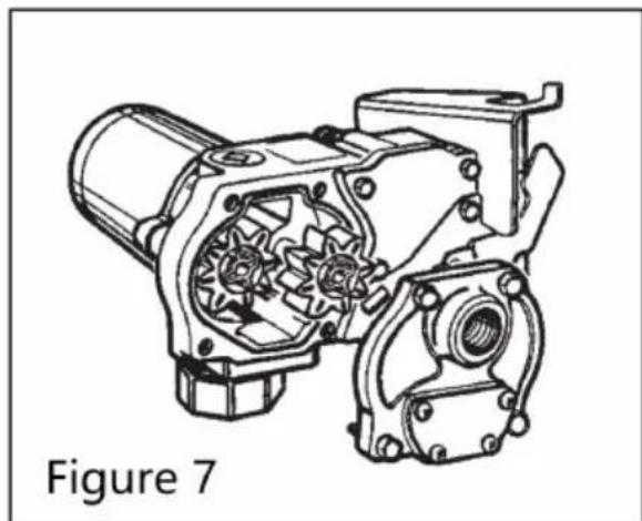
- Inspect the gears and key for wear and damage. Replace, as necessary.
- Wipe the gear cavity with a clean cloth.
- Replace the gears. Make sure they turn freely.
- Replace the drive key.
- Make sure the gear cover plate O-ring is securely in place. Tighten the coplate to the housing.
Clean or Replace Bypass Poppet
- Turn the pump OFF and disconnect from power.
- Using a drive ratchet or extension, remove the pipe plug from the top out (Figure 8)
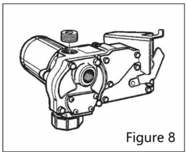
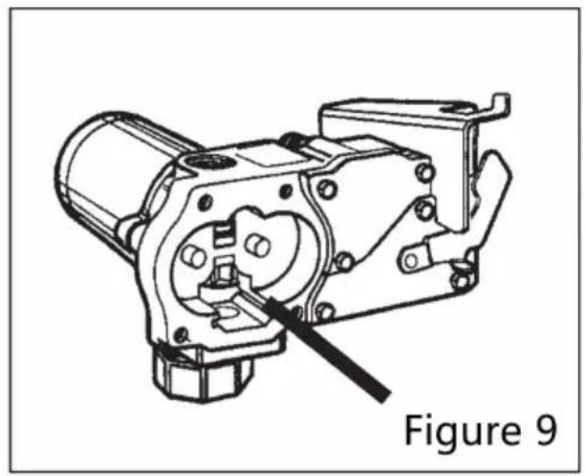
- Using a clean cloth, rotate the poppet and clean it
To check the sealing surface of the poppet valve to see if there is any damage, so, please replace it immediately. (Figure 9) - Install the pipe plug again. Replace the gears and drive key. Make sure go turn freely with the key removed.
- Make sure the gear cover plate O-ring is in place. Tighten the cover plate pump housing.
Replace Power Switch
Turn the pump OFF and disconnect from power. Remove the switch cover plug from the pump housing. (Figure 10)
- Turn the pump OFF and disconnect from power.
- Remove the switch cover plate from the pump housing. (Figure 10)
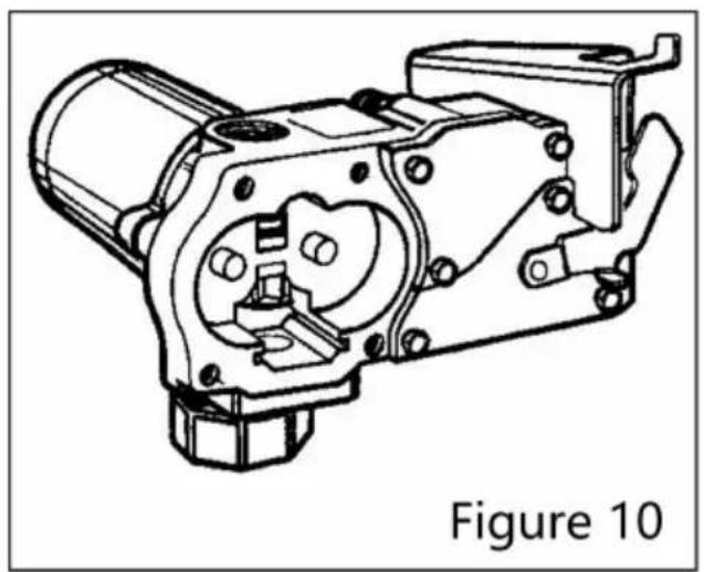
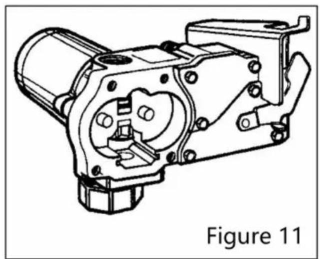
- Remove the torx head screw, then remove the switch assembly. (Figure 1)
- Remove one pump wire from the back of the switch and one wire from the protector.
- Install a new switch by reversing the above procedure. Insert the switch assembly into the pump cavity. Place the red wire between the circuit break and the wall of the pump. Make sure the O-ring is seated properly before tightening the switch cover plate.
NOTE: For the proper operation of the switch lever and cam, attach the mo1 plate to the switch with a clearance of 0.175 or about 3/16 inch. (Figure
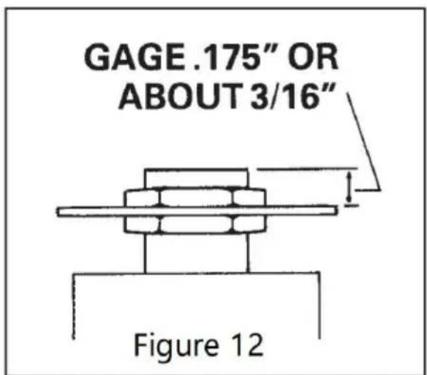
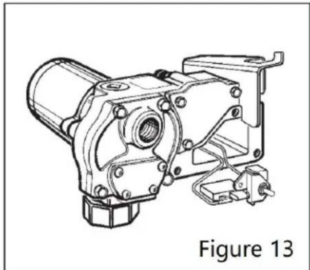
Remove switch bracket mounting screw and gently pull switch from switch case (Figure 13)
- Remove the red wires from the terminals on the back of the switch.
- Remove the remaining wire on motor protector then remove the motor protor from switch cavity.
- Install new motor protector by reversing above procedure.
NOTE: Make sure the O-ring is seated properly before tightening the switch on plate.
Replace Switch Lever or Switch Lever Shaft O-Ring
- Turn off the pump and disconnect from power.
- Remove the switch cover plate from the pump housing.
- Remove the screw connecting the switch cam to the cover plate.
- Remove the cam and switch lever.
- Replace the switch lever or switch lever shaft O-ring as needed.
- Reassemble by reversing the above procedure. Make sure the O-ring is set properly before tightening the cover plate.
Replace Motor Shaft Seal
- Turn the pump OFF and disconnect from power.
- Remove the gear cover plate, gears, and drive key as described in Gear Replacement instructions.
- Remove the motor from the pump housing.
- Remove the motor shaft seal by prying out with a small screwdriver. (Figure 1)
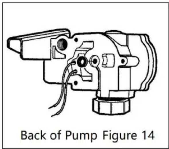
- Lubricate the gear shaft with WD-40 or a similar penetrating oil.
- Press a new motor shaft seal evenly in the pump housing until seated. Lu the seal with a lightweight motor oil.
- Gently slide the shaft through the seal until the motor is flush against the housing.
- Tighten the motor to the pump housing. Check for proper installation by using a .0015 feeler gauge around the motor flange. The gauge should not fit both the flange and the housing.
- Install the gears and drive key as described in Gear Replacement instructric
COMMON TROUBLESHOOTING
| Symptom | Cause | Cure |
| A. MOTOR DOES NOT RUN | 1. Fuse blown2. Switch defective3. Motor burned out4.Switch or electrical connections faulty5. Circuit breaker tripp | Inspect fuse in fuse holder on power cord. If replace.Remove switch cover plate and inspect switch. Replace, if necessary.Replace motor as described in the Repair SectInspect for damaged motor protector, defective or switch, or improper electrical connections.Replace as needed and re-install.Turn power off at source. Inspect the pump thclean or repair Reset circuit breaker by turning the power swit then back on. |
| B. MOTOR RUN BUT DOES NOT PUMP | 1. Suction pipe clogged damaged, or missing2. Gear cover plate oO-ring damaged3. Strainer clogged or defective4. Bypass poppet bind or damaged5. System air leak6. System air lock7. Poor connections olow voltage8. Fuel level low9. Motor running backwards due to incorrect polarity | Remove pump from tank. Inspect suction pipe.or replace, as necessary.Remove and inspect the cover plate and O-ringReplace, as necessary. Refer to the Repair SeServicing O-rings.Remove strainer cover plate. Remove and clearstrainer. Install again.USing instructions in the Repair Section, remove bypass poppet, spring, and O-ring. Clean cavityInspect and replace components, asnecessary.Tighten all pump fittings and connections. Inspe suction pipe for leaks or damage.This can occur if external filter, meters, or an off-the-shelf automatic nozzle is used. To correctremove the pipe plug in the top outlet port argear cavity with fuel. Use of a factory-suppliedautomaticnozzle is recommended.Make sure electrical connections are secure. Alcheck battery voltage. Fill tank Connect red wire to positive (+) ungrounded sixbattery. Gear with key should turn counterclock |
| C. LOW FLOWRATE | 1. Poor connections olow voltage | Make sure electrical connections are secure. Alcheck battery voltage Remove the strainer cover |
| 2. Strainer partially clogged 3. Suction pipe clogging or damaged 4. Fuel tank empty 5. Using off-the-shelf automatic nozzle 6. System air leak 7. Bypass poppet spi weak | Remove and clean the strainer. Install again. Remove pump from tank. Inspect pipe. Clean or replace, as necessary. Fill tank. Factory-supplied automatic nozzle is recommende Tighten all pump fittings and connections. Inspe suction pipe for leaks or damage. Replace, as necessary. Using instructions in the Repair Section, remove bypass poppet and inspect spring. Replace, if necessary. | |
| D. MOTOR STALLS WHEN OPERATING IN BYPASS MODE | Motor protector activate Gears locked 3. Wiring defective 4. Bypass poppet bind or damaged 5. Motor defective | Turn off switch. Allow motor to cool, then turn switch. Remove gear cover plate and inspect gears an key. Make sure gears turn freely with the key Replace, if worn. Use Wiring instructions in the Installation Sectio ensure proper connections. Using instructions in the Repair Section, remove bypass poppet, spring, and O-ring. Clean cavity Inspect components and replace, as necessary. Replace motor as described in the Repair Sect |
| E. SWITCH FAIL TO OPERATE MOTOR | 1. Motor burned out 2. Motor protector activated 3. Switch or electrical connections faulty | Replace motor as described in the Repair Sect Turn off switch. Allow motor to cool, then turn switch. Inspect for damaged motor protector, blown fus defective wiring or switch, or improper electrical connections. Replace as needed and re-install. |
| F. RAPID OVERHEATING OF MOTOR | 1. Duty cycle too long 2. Strainer clogged 3. Suction pipe clogging or damaged 4. Gears worn 5. Fuel level low 6. Running too long i bypass mode | Pump operation should not exceed the standard cycle of 30 minutes ON, and 30 minutes OFF the pump to cool for 30 minutes. Remove strainer cover plate. Remove and clear strainer. Install again. Remove pump from tank. Inspect suction pipe. or replace, as necessary. Remove gear cover plate and inspect gears an key. Make sure gears turn freely with key rem Replace, if necessary. Fill tank. Limit bypass operation to 10 minutes. |
Manufacturer: Shanghaiuxinmuyeyouxianggsi
Address: Shuangchenglu 803nong11hao1602A-1609shi, baoshanqu, shanghai 200000 CN.
Imported to AUS: SIHAO PTY LTD, 1 ROKEVA STREETEASTWOOD NS 2122 Australia
Imported to USA: Sanven Technology Ltd., Suite 250, 9166 Anaheim Pla Rancho Cucamonga, CA 91730
EC
REP
E-CrossStu GmbH
Mainzer Landstr.69, 60329 Frankfurt am Ma
UK
REP
YH CONSULTING LIMITED.
C/O YH Consulting Limited Office 147, Centurion H
London Road. Staines-upon-Thames. Surrey. TW18 4
VEVOR®
TOUGH TOOLS, HALF PRICE
This product shall not be used for pumping fuel or other liquids into aircraft.
C/O YH Consulting Limited Bureau 147, Centurion House, London Road, Staines-upon-Thames, Surrey, TW18 4AX
VEVOR®
TOUGH TOOLS, HALF PRICE
Assistance technique et certificat de garantie electronique www.vevor.com/support
VEVOR®
TOUGH TOOLS, HALF PRICE
This product shall not be used for pumping fuel or other liquids into aircraft.
C/O YH Consulting Limited Office 147, Centurion House, London Road, Staines-upon-Thames, Surrey, TW18 4AX
VEVOR®
TOUGH TOOLS, HALF PRICE
This product shall not be used for pumping fuel or other liquids into aircraft.
Importato in AUS: SIHAO PTY LTD, 1 ROKEVA STREETEASTWOOD NSW 2122 Australia
Importato negli USA: Sanven Technology Ltd., Suite 250, 9166 Anaheim Place, Rancho Cucamonga, CA 91730
E-CrossStu GmbH
Mainzer Landstr.69, 60329 Francoforte sul Meno.
CONSULENZA YH LIMITATA.
C/O YH Consulting Limited Ufficio 147, Centurion House, Via Roma, 101, 00186 Roma, Italia
VEVOR®
TOUGH TOOLS, HALF PRICE
Soporte专业技术o y certificate de garantia electrònica www.vevor.com/support
BOMBA DE TRANSFERENCIA DE COMBUSTIBLE DE CC
MODELO: KEX-15
Importado a Australia: SIHAO PTY LTD, 1 ROKEVA STREETEASTWOOD NSW 2122 Australia
Importado a EE. UU.: Sanven Technology Ltd., Suite 250, 9166 Anaheim Place, Rancho Cucamonga, CA 91730
E-CrossStu GmbH
Mainzer Landstr.69, 60329 Francfort del Meno.
YH CONSULTING LIMITADA.
C/O YH Consulting Limited Oficina 147, Centurion House, Carretera de Londres, Staines-upon-Thames, Surrey, TW18 4AX
VEVOR
TOUGH TOOLS, HALF PRICE
Importowane do AUS: SIHAO PTY LTD, 1 ROKEVA STREETEASTWOOD NSW 2122 Australia
Importowane do USA: Sanven Technology Ltd., Suite 250, 9166 Anaheim Place, Rancho Cucamonga, CA 91730
E-CrossStu GmbH
Mainzer Landstr.69, 60329 Frankfurt nad Menem.
YH CONSULTING LIMITED.
C/O YH Consulting Limited Biuro 147, Centurion House, London Road, Staines-upon-Thames, Surrey, TW18 4AX
VEVOR
TOUGH TOOLS, HALF PRICE
Technische ondersteuning en e-garantiecertificaat www.vevor.com/support
DC BRANDSTOFOVERDRACHTPOMP
MODEL: KEX-15
HULP NODIG? NEEM CONTACT MET ONS OP!
ALGEMENE PROBLEEMOPLOSSING
C/O YH Consulting Limited Kantoor 147, Centurion House, London Road, Staines-upon-Thames, Surrey, TW18 4AX
VEVOR®
TOUGH TOOLS, HALF PRICE
C/O YH Consulting Limited Office 147, Centurion House, London Road, Staines-upon-Thames, Surrey, TW18 4AX