HXCZDJ-07 - Hoist Vevor - Free user manual and instructions
Find the device manual for free HXCZDJ-07 Vevor in PDF.

| Product Type | Truck Crane (Hoist) |
| Brand | Vevor |
| Model | HXCZDJ-07 |
| Maximum Lifting Capacity | 500 lb (approx. 227 kg) |
| Lifting Height | 150 to 200 cm |
| Hydraulic Jack | Max 8 tons |
| Rotation Angle | 360 degrees |
| Material | Steel with powder coating |
| Telescopic Boom | Yes |
| Manual Winch | Yes |
| Tow Bar | Yes |
| Support Leg | Yes |
| Safety | Hook safety latch, hydraulic relief valve |
| Maintenance | Frequent inspection, periodic lubrication, annual hydraulic oil replacement |
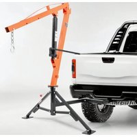
| Usage | Mount on truck receiver hitch, for lifting loads |
| Assembly | Detailed instructions included (6 steps) |
Frequently Asked Questions - HXCZDJ-07 Vevor
User questions about HXCZDJ-07 Vevor
0 question about this device. Answer the ones you know or ask your own.
Ask a new question about this device
Download the instructions for your Hoist in PDF format for free! Find your manual HXCZDJ-07 - Vevor and take your electronic device back in hand. On this page are published all the documents necessary for the use of your device. HXCZDJ-07 by Vevor.
USER MANUAL HXCZDJ-07 Vevor
Technical Support and E-Warranty Certificate
www.vevor.com/support
TRUCK CRANES USER MANUAL
MODEL:HXCZDJ-07
We continue to be committed to provide you tools with competitive price.
"Save Half", "Half Price" or any other similar expressions used by us only represents a estimate of savings you might benefit from buying certain tools with us compared to the top brands and doses not necessarily mean to cover all categories of tools offered by us are kindly reminded to verify carefully when you are placing an order with us if you actually saving half in comparison with the top major brands.
MODEL:HXCZDJ-07
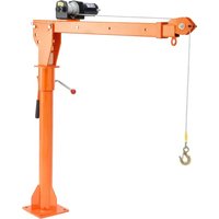
natural_image
Line drawing of a mechanical lifting device with lever and base mount (no text or symbols)Photo for reference
NEED HELP? CONTACT US!
Have product questions? Need technical support? Please feel from contact us:
Technical Support and E-Warranty Certificate www.vevor.com/support
This is the original instruction, please read all manual instruction carefully before operating. VEVOR reserves a clear interpretation user manual. The appearance of the product shall be subject to product you received. Please forgive us that we won't inform you there are any technology or software updates on our product.
WARNING
- Read carefully and understand all ASSEMBLY AND
OPERATION INSTRUCTIONS before operating.
- Failure to follow the safety rules and other basic safety precaution may result in serious personal injury.
GENERAL SAFETY RULES
-
Never overload.
-
The load is maximum when the arm of the product is adjusted to the shortest. The load of the product decreases as the arm increases.
-
Always wear ANSI-approved safety goggles.
-
Always wear hearing protection when working in noisy environments. Prolonged exposure to high-intensity noise can cause hearing loss.
-
Use safety equipment. Safety shoes, hard hats and work gloves m be used for applicable conditions.
-
Dress appropriately. Never wear loose, long hair, and keep hair, cl and gloves away from moving parts.
-
Use common sense when working. Stay alert and concentrate when setting up and using this Crane. Never work while under the influence of alcohol, drugs or medications.
-
Keep the work area clean and well-lighted while assembling and using the Crane. Keep spectators and children out of the work area.
-
This Crane is designed to be positioned outside the truck bed, an attached to the vehicle via the receiver hitch. It is portable and easy adjust to different boom positions for 125, 250 and 500 Lbs maximum capacity. Please do not modify the Crane or use this product for pur it was not designed for.
-
When attaching the load to Hook with Chain, use appropriate couplings rated to handle the load. Collars must be fully engaged on Hook, with the Hook's safety latch closed.
-
Never lift people or animals. Keep children and spectators clear the area under and around the lifted cargo. When operating the Crane stay clear of the space between the Crane and the load.
-
Before each use, inspect the Crane, the Long Ram Jack and the Hook for damage, corrosion and any other condition that might be the safe performance of this product.
- Only set up the Crane when the pickup truck is off the highway clear location that is away from oncoming traffic.
- Before lifting cargo into the truck bed, make sure the truck's eng OFF with automatic transmission in PARK. Manual transmission vehicle should be in gear. Chock all wheels for added safety.
- When using this product, adhere to all Department of Transportation (D.O.T.) requirements.
- Note the position of the vehicle's exhaust pipes before setting up Crane. Flammable goods being lifted by the Crane could come in co with still-hot exhaust pipes and catch fire.
- Setting up the Crane and maneuvering heavy cargo on the Crane be strenuous and dangerous. This should only be done by individuals can physically handle the demands of these tasks.
- The Crane is for lifting purposes only, not for supporting loads. It supports the load with appropriate jack stands or equivalent, if immediate loading or unloading is impossible. Do not leave a suspended load unattended.
- Remove the Crane from the vehicle's receiver hitch when Crane in use.
- Always be aware of dynamic loading. An excess load may be cr briefly by a sudden tug or weight gain, which can damage the Crane the cargo, and/or cause personal injury.
- Keep in mind that the warnings previously discussed cannot cover possible events and circumstances. It is important that the person set up, loading/ unloading and using this product use common sense at a times.
SAVE THESE INSTRUCTIONS
MODEL AND PARAMETERS
| Model | HXCZDJ-07 |
| Bracket Capacity | Max. 500LBS |
| Hoisting Height | 150~200cm |
| Hydraulic Jack | Max. 8Ton |
| Rotation Angle | 360 degree |
| Material | Powder-coated Steel |
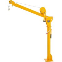
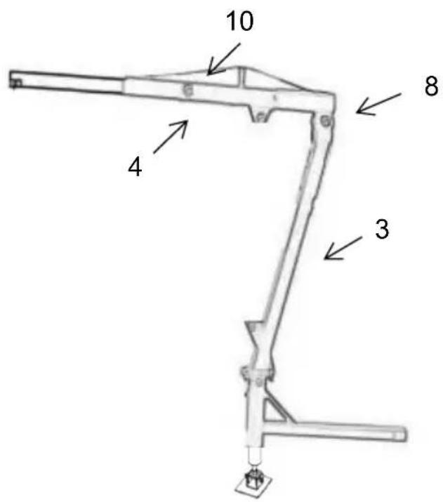
STRUCTURE DIAGRAM
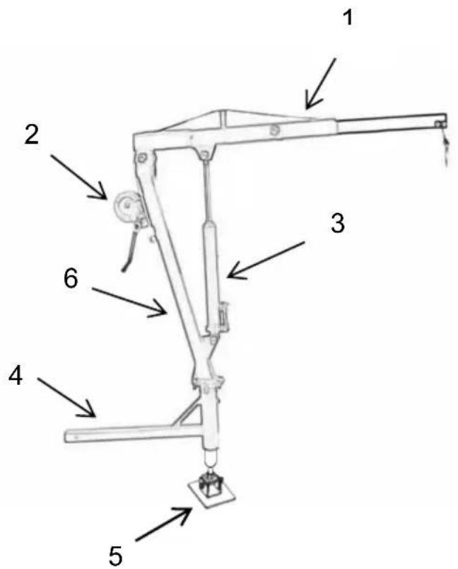
- Telescopic Boom
- Hand winch
- Hydraulic Jack
- Trailer Bar
- Supporting Leg
- Upright Rod
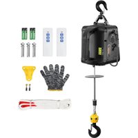
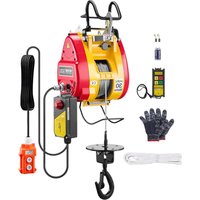
COMPONENTS
| No. | Picture | Name and Q' | No. | Picture | Name and Q'ty |
| 1 | 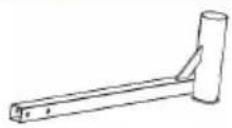 | Trailer Bar(× 1) | 8 | 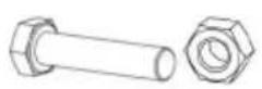 | Bolt M16*100(×1) |
| 2 |  | hydraulic jack(× 1) | 9 | 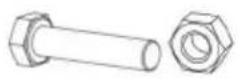 | Bolt M12*30(×6) |
| 3 | 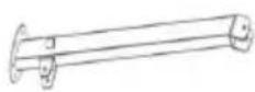 | Upright Rod(× 1) | 10 | 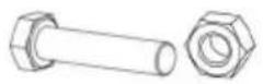 | Bolt M12*80(×2) |
| 4 | 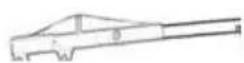 | Boom(× 1) | 11 |  | Bolt M10*90(×3) |
| 5 |  | Supporting Leg(× 1) | 12 | 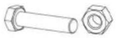 | Bolt M16*90(×2) |
| 6 | 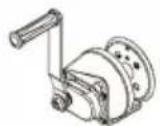 | Hand with(× 1) | 13 | 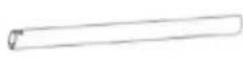 | Jack handle(× 1) |
| 7 | 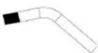 | Long Screw(× 1) | 14 | 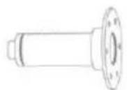 | User manual× 1) |
| 15 |  | Hook withChain(×1) | 16 | / | User manual(× 1) |
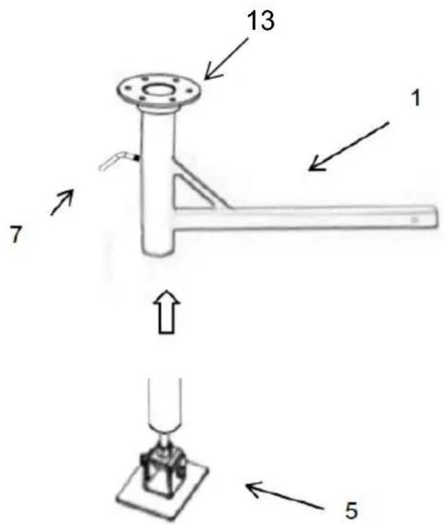
Step 1: Insert (13) into tow bar (1); slowly insert support leg (5) into long screw (7) to prevent swivel head from rotating.
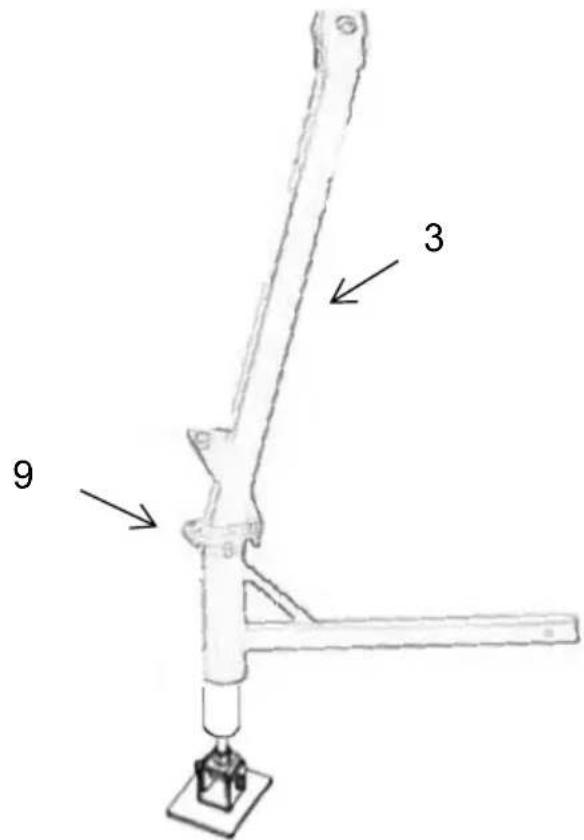
Step 2: Install the upright rod(3), and lock it with (9) bolts, washers nuts.
Step 3: Install telescoping arm (4), connecting (4) and (3) with bolt (and lock it with washers and nuts. Use the bolt to (10) Adjust the the inner arm.
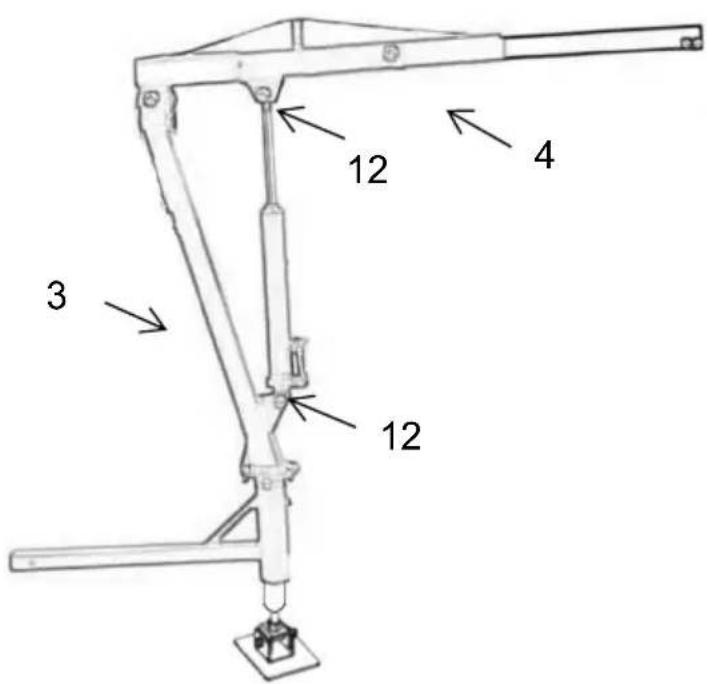
Step 4: Install the hydraulic jack. Connect 4 and 3 with two bolts (1 and lock it with washers and nuts.
Step5: Attach the manual winch to the upright bar again with the 3(11), pull out the wire rope and pass it through the pulley on the first section of the telescoping arm.
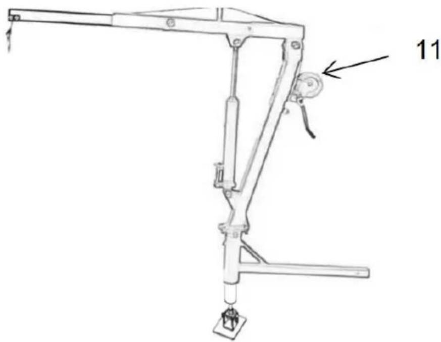
natural_image
Technical line drawing of a mechanical lever assembly with labeled component (11), no readable text or symbols beyond labelStep 6: Connect the product to the vehicle and it is ready to use.
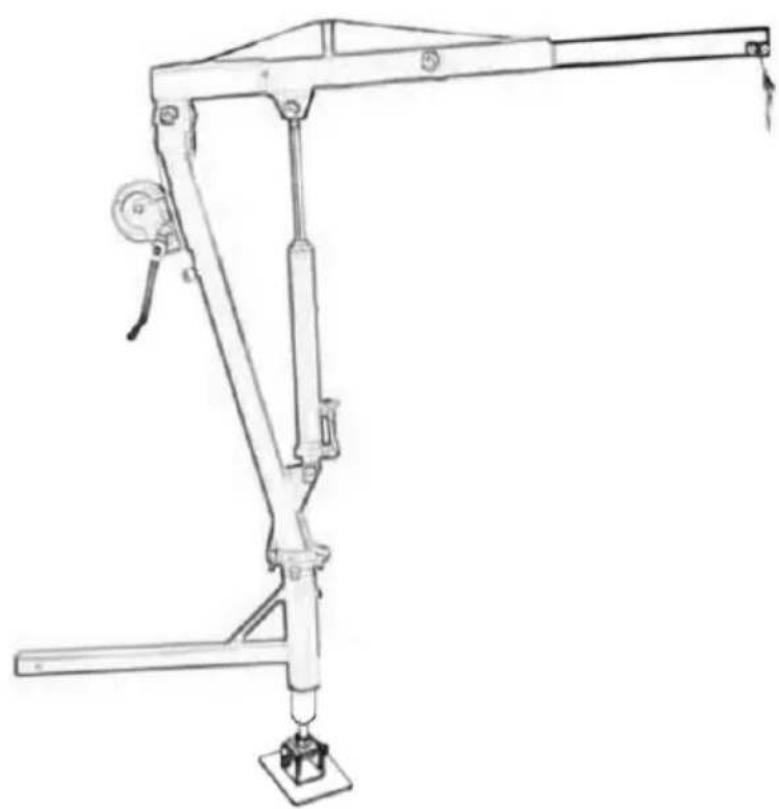
natural_image
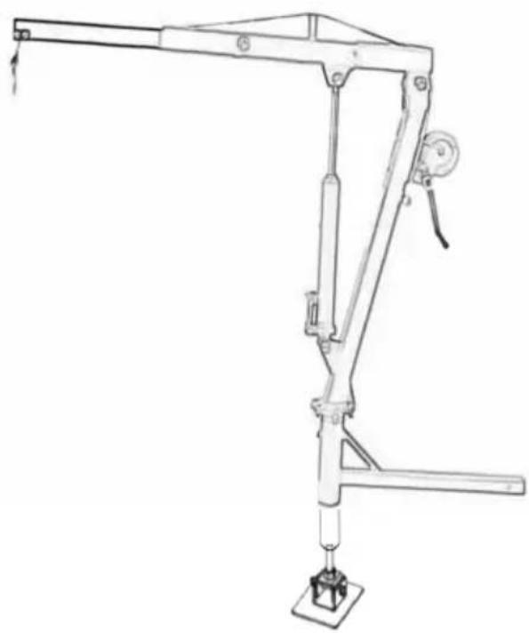
Line drawing of a manual crane with handle and base mount (no text or symbols)Operation:
1) Make sure the installation is correct and all parts are locked.
2) The boom can be rotated and must be locked before lifting.
3) Know the weight of the cargo to be lifted. The cargo must be prstrapped and have attachment couplings that will attach to the hook.
Attach the cargo to the hook.
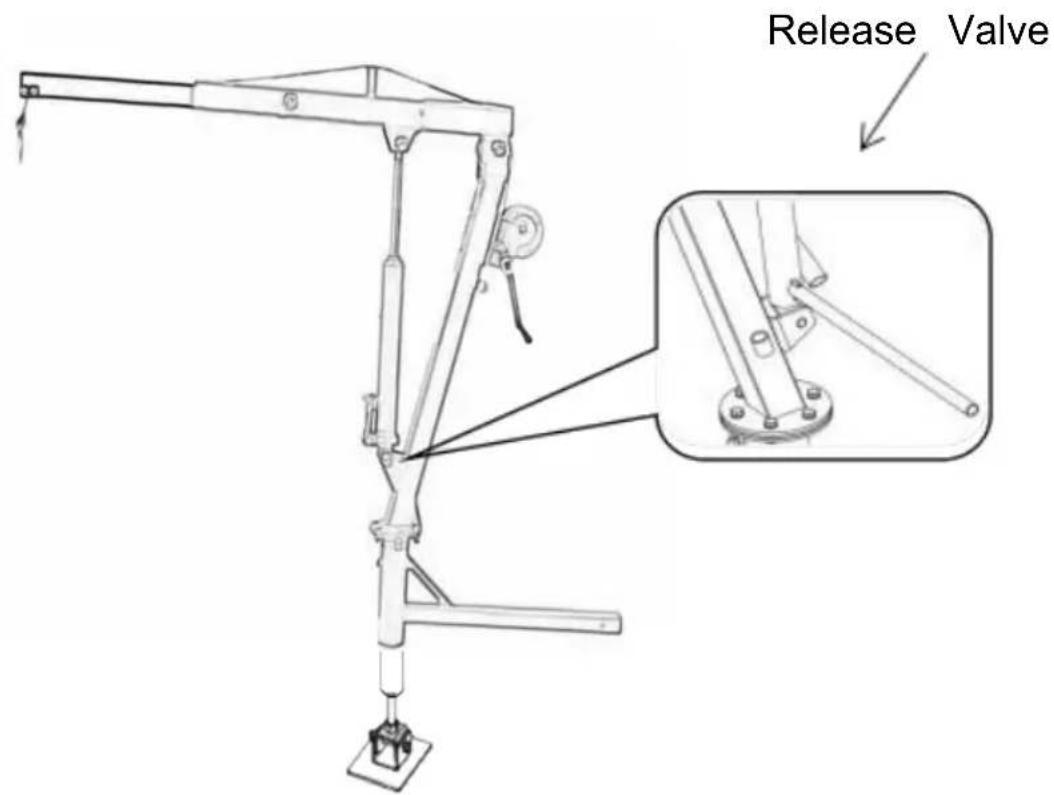
4) Use the jack handle to close the hydraulic release valve (turn close completely), and then pump the jack handle to raise the boom and the cargo slowly.
5) With the cargo raised, the upright rod can be rotated to move th into the truck bed.
6) With the cargo positioned over the truck bed, slowly turn the hydraulic release valve counterclockwise and the cargo will be lowered to the 1 bed.
7) Remove the cargo's coupler from the boom hook and swing back Boom to its original position.
Note: Be alert as the Boom will quickly descend to its lowest positio
MAINTENANCE
- Frequently check the condition of the hydraulic crane hoist.
- Do not use a damaged crane.
- Make sure all components are in good condition. If the crane or receiver hitch becomes damaged by an accident or any other type of damage is noted, it should be replaced.
- Check to make sure that all hardware is tightly secured in place 5. Keep the Crane clean and periodically lubricate moving parts.
- Replacing hydraulic oil: It is important that hydraulic oil be replaced least once per year (or more, if Crane is frequently used). Only use good quality hydraulic oil and never mix different oil brands together.
 | Warning - To reduce the risk of injury, user must read instructions manual carefully |
 | Wear head protection |
VEVOR®
TOUGH TOOLS, HALF PRICE
Technical Support and E-Warranty Certificate
www.vevor.com/support
VEVOR®
TOUGH TOOLS, HALF PRICE
natural_image
Technical line drawing of a mechanical lifting device with lever and base mount (no text or symbols)Exigences du DOT (Digital Transportation Authority).
natural_image
Technical line drawing of a mechanical lever assembly with labeled component (11), no text or symbols presentnatural_image
Line drawing of a mechanical lever assembly with no text or symbolsOpération:
www.vevor.com/support
BENUTZERHANDBUCH FÜR LKW-KRANE MODELL:HXCZDJ-07
natural_image
Technical line drawing of a mechanical lifting device with lever and base mount (no text or symbols)Foto als Referenz
natural_image
Technical line drawing of a mechanical lever assembly with labeled component (11), no readable text or symbols beyond labelnatural_image
Line drawing of a manual lever mechanism with no text or symbolsBetrieb:
WARTUNG
www.vevor.com/support
VEVOR®
TOUGH TOOLS, HALF PRICE
natural_image
Technical line drawing of a mechanical lifting device with lever and base mount (no text or symbols)Foto di riferimento
natural_image
Technical line drawing of a mechanical lever assembly with labeled component (11), no readable text or symbols beyond labelnatural_image
Line drawing of a mechanical lever assembly with no text or symbolsOperazione:
www.vevor.com/support
MANUAL DE USUARIO DE GRÚAS SOBRE CAMIONES
MODELO:HXCZDJ-07
natural_image
Technical line drawing of a mechanical lifting device with lever and base mount (no text or symbols)Foto de referencia
- Pluma telescópica
- Cabrestante manual
- Gato hidráulico
- Barra de remolque
- Pierna de apoyo
- Varilla vertical
COMPONENTES
natural_image
Technical line drawing of a mechanical lever assembly with labeled component 11 (no text or symbols beyond label)natural_image
Line drawing of a mechanical lever assembly with no text or symbolsOperación:
www.vevor.com/support
VEVOR®
TOUGH TOOLS, HALF PRICE
natural_image
Technical line drawing of a mechanical lifting device with lever and base mount (no text or symbols)natural_image
Technical line drawing of a mechanical lever assembly with labeled component (11), no readable text or symbols beyond labelnatural_image
Line drawing of a mechanical lever assembly with no text or symbolsMachine Translated by Google
Działanie:
natural_image
Technical line drawing of a mechanical crane with lever and base mount (no text or symbols)Foto ter referentie
HULP NODIG? NEEM CONTACT MET ONS OP!
www.vevor.com/support
- Telescopische giek
- Handler
- Hydraulische krik
- Aanhangwagenstang
- Steunbeen
- Staande staaf
COMPONENTEN
natural_image
Technical line drawing of a mechanical lever assembly with labeled component (11), no readable text or symbols beyond labelnatural_image
Line drawing of a mechanical lever assembly with no text or symbolsWerking:
www.vevor.com/support
LASTBIRKRANAR ANVÄNDARHANDBOK MODELL:HXCZDJ-07
natural_image
Technical line drawing of a mechanical lifting device with lever and base mount (no text or symbols)Foto för referens
BEHÖVER HJÄLP? KONTAKTA OSS!
natural_image
Technical line drawing of a mechanical lever assembly with labeled component (11), no readable text or symbols beyond labelnatural_image
Line drawing of a mechanical lever assembly with no text or symbolsDrift:
www.vevor.com/support