FF-T809 - Car accessory Vevor - Free user manual and instructions
Find the device manual for free FF-T809 Vevor in PDF.


User questions about FF-T809 Vevor
0 question about this device. Answer the ones you know or ask your own.
Ask a new question about this device
Download the instructions for your Car accessory in PDF format for free! Find your manual FF-T809 - Vevor and take your electronic device back in hand. On this page are published all the documents necessary for the use of your device. FF-T809 by Vevor.
USER MANUAL FF-T809 Vevor
Technical Support and E-Warranty Certificate www.vevor.com/support
TOW BAR
MODEL: FF-T809
We continue to be committed to provide you tools with competitive price. "Save Half", "Half Price" or any other similar expressions used by us only represent of savings you might benefit from buying certain tools with us compared top brands and does not necessarily mean to cover all categories of tools offered are kindly reminded to verify carefully when you are placing an order with us actually saving half in comparison with the top major brands.
VEVOR®
TOUGH TOOLS, HALF PRICE
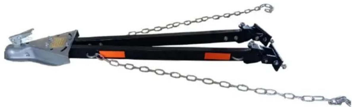
TOW BAR
MODEL: FF-T809
natural_image
Mechanical tool with chain links and orange safety stripes (no text or symbols visible)NEED HELP? CONTACT US!
Have product questions? Need technical support? Please feel from contact us:
Technical Support and E-Warranty Certificate www.vevor.com/support
This is the original instruction, please read all manual instruction carefully before operating. VEVOR reserves a clear interpretation user manual. The appearance of the product shall be subject to product you received. Please forgive us that we won't inform you there are any technology or software updates on our product.
SAFETY INSTRUCTIONS
WARNING
Failure To Follow These Instructions May Result In A Hazardou
Towing Condition.
- Total weight of the towed vehicle must not exceed 5500 lbs.
- Towing vehicle must weigh more than towed vehicle.
- Install per the instructions provided.
- Follow towed vehicle manufacturer's towing recommendations. Transmission must be neutral. The parking brake must be released. Some vehicles with power steering may "follow" better with the engine idling.
- Steering wheel of towed vehicle must be free to turn.
- Do not allow passengers to ride in towed vehicles.
- Towed vehicle's taillights, turn signals, and brake lights should function when being towed. Otherwise, the vehicle should be fitted with a temporary lighting system.
- Added weight of the towed vehicle will increase the stopping distance. Allow this in your driving.
- When making turns begin by rolling straight forward, then turn the wheel.
- Do not exceed 45 miles per hour.
- Do not back up with the vehicle in tow.
- Check all connections, including hitch and ball, before towing and often dur your trip.
- Remove the tow bar when not towing.
- Use only a 2" ball rated for at least 5500 lbs.
- Properly connect safety chains from the tow bar to towing and towed vehicle
- Read and follow the label on the side of the tow bar. Coupler and instruct before towing.
USAGE NOTES
- Never exceed the lowest rating of any part of your towing system.
- Use this tow bar to tow only vehicles in good condition. Do not tow vehicle with damaged steering or surension systems.
- Inflate the tires of the towed vehicle to the maximum pressure recommended by the tire manufacturer.
- Towng mirrors on both sides of towing vehicle add to safety by increasing rear visibility and are required by state laws.
- Allow more time for accelerating, stopping, and maneuvering. Slow down well before sharp curves, obstacles, or lane changes and before starting down hills.
- If the vehicle combination sways or seems unstable, gradually slow down, pull off the road to a safe location, and inspect all connections. Instability increases with speed, and you may have to tow at a lower speed. Discontinue towing if instability persists. A combination that is stable and easy to control at low speed may be unstable at a higher speed. Stability decreases when going downhill. Start downhill slowly and maintain a low speed.
- Do not make sharp turns from a complete stop.
- Reduce speeds on rough roads.
Special Instructions for using a Pickup Truck or Van as the Towing Vehicle:
- Pickup or van must weigh 1-1/2 times as much as the towed vehicle. Example to tow 3000lb. Car, pickup, or van must weigh at least 4500 lb.
- If towing vehicle does not weigh enough, weight must be added to prevent dangerous towing combination. Instability can lead to loss of control and/or a "jackknife" condition.
- Some step bumpers restrict turning. Use extra caution. Turning too sharply can damage the tow bar, the hitch ball, and the bumper.
MODEL AND PARAMETERS
| Model | FF-T809 |
| Max. Towing Capacity | 5500lbs |
| Opening And Closing Width | 39.4" Max |
| Coupler | 2" |
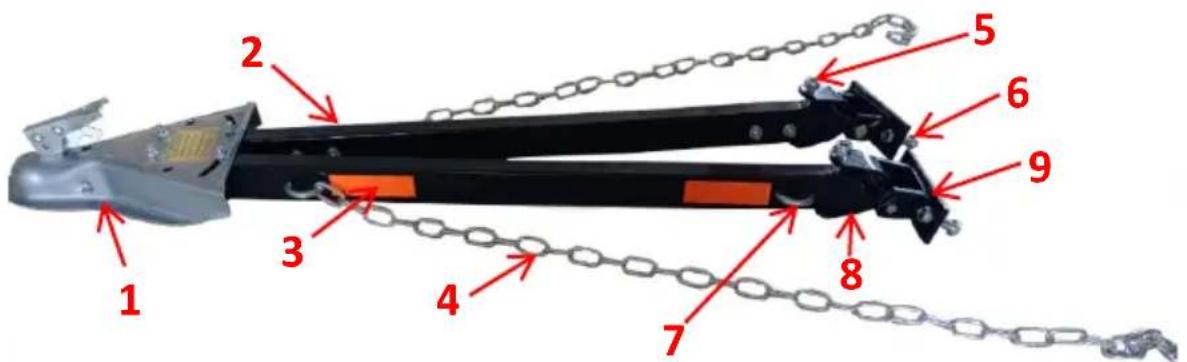
STRUCTURE DIAGRAM AND COMPONENTS
text_image
Labeled diagram of a mechanical device with numbered parts and chains, showing components like lever, chain, and lock.| No. | Name | Qty |
| 1 | Coupler(2") | 1 |
| 2 | Tow Bar | 2 |
| 3 | Reflective Sticker | 4 |
| 4 | Safety Chain(1.2m) | 2 |
| 5 | Bolt (Φ 12*80mm) | 2 |
| 6 | Bolt (Φ 12*45mm) | 4 |
| 7 | U-bolt | 2 |
| 8 | U-shaped Connector | 2 |
| 9 | Mounting Bracket | 2 |
| 10 | User Manual | 1 |
INSTALLATION NOTES
- This tow bar will be installed by a professional installer/fabricator experienced in selecting vehicle attachment areas with adequate strength.
- Park vehicles on level ground for installation.
- The coupler must be level within when the attachment is complete, as
shown. Must be level within 5

text_image
Must be level within 5°- Bumper attachments should be reinforced, as shown below.
- Attachments to the towed vehicle should be bolted, not welded.
- Keep the mounting surface of brackets as close to being flush with the front the bumper as possible to allow free vertical travel.
- Attach the tow bar to properly mounted brackets with pins and secure it with the attached wire.
- Adjust the coupler for proper fit to the ball; see coupler adjustment.
- Avoid suspension and brake components with attachments.
TOWED VEHICLE ATTACHMENT
A structure must be fabricated to allow the tow bar to be attached to the frame of the towed vehicle. Some typical frame attachment structures are shown below.
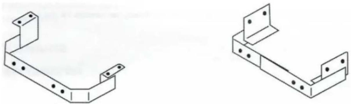
natural_image
Two technical line drawings of metal bracket components with mounting holes and mounting holes (no text or symbols)If the bumper is used for support, it must be reinforced with frame attachment. A typical way of reinforcing a bumper is shown below.
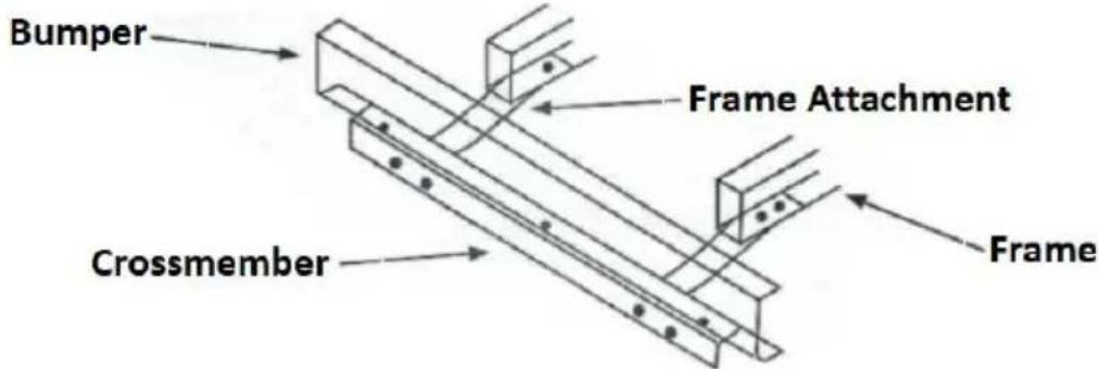
text_image
Bumper Frame Attachment Crossmember FrameThese frame attachments should be attached within 2" of the tow bar brackets to be connected. These frame attachments should be made from at least 1/2" 2" flat bar stock. Never attaches through plastic fascia covering a bumper. With customer approval, this fascia must be trimmed to provide a secure attachment
COUPLER
COUPLER ADJUSTMENT:
- With the coupler locked onto a 2" dia. ball, tighten the locknut until all parts are clamped solid.
NOTE: DO NOT OVERTIGHTEN. JUST TIGHTEN ENOUGH TO FULLY COMPRESS HELICAL SPRING. - Back locknut off 1/2 to 3/4 turn.
- Check for proper couple/uncouple operation.
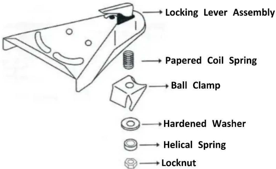
text_image
Locking Lever Assembly Papered Coil Spring Ball Clamp Hardened Washer Helical Spring LocknutINSTALLATION
- Center the tow bar on the attachment surface, spreading side arms to at least 24", and mark the tow bar bracket centerlines.
- Using the tow bar bracket as a template, drill two 1/2" holes into the attachment surface on each side.
- Attach tow bar brackets to the attachment surface using the 1/2 x 1-3/4 Gr5 bolts supplied with the tow bar.
NOTE: IF LONGER BOLTS ARE NEEDED, USE 1/2-13 Gr5 BOLTS.
- Fasten the tow bar brackets with flat washers and locknuts, as shown below.
- Tighten these 1/2" fasteners to 75 lb-ft..
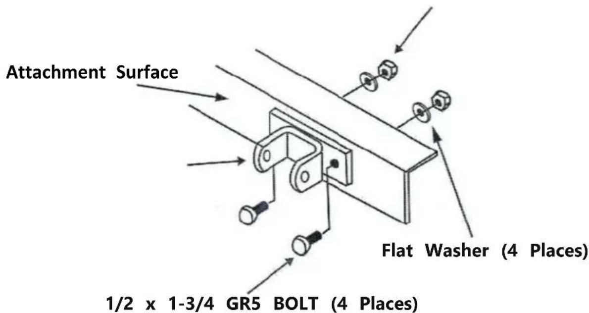
text_image
Attachment Surface Flat Washer (4 Places) 1/2 x 1-3/4 GR5 BOLT (4 Places)HOOK-UP
- Attach the tow bar to the tow bar brackets with two wire lock pins.
- Attach the tow bar coupler to the 2" ball of the towing vehicle.
- Center coupler on tow bar side arms so that the tow bar is symmetrical about the centerline of the vehicles.
- Tighten the nuts which attach the tow bar side arms to the coupler to 31 ll
- Install the safety chains as described in the next section.
- Connect an adequate wiring harness so that stoplights, turn signals, and taillights operate on a towed vehicle in conjunction with towing vehicle's lights.
- Read and follow labels located on the tow bar.
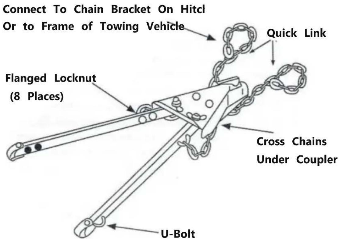
USE SAFETY CHAIN :
-
Connect safety chains to both vehicles and the tow bar itself.
-
Attach chains to the tow bar with U-bolts and flanged locknuts.
-
Tighten each flanged locknut until U-bolt threads extend past locknut.
-
Cross two chains under the coupler and connect to the chair bracket on the hitch or to the frame of towing vehicle allowing only enough slack to permit turning.
text_image
Connect To Chain Bracket On Hitcl Or to Frame of Towing Vehicle Quick Link Flanged Locknut (8 Places) Cross Chains Under Coupler U-BoltMAINTENANCE
- Check bolts and safety pins regularly.
- Do not overload.
VEVOR®
TOUGH TOOLS, HALF PRICE
Technical Support and E-Warranty Certificate
www.vevor.com/support
VEVOR®
TOUGH TOOLS, HALF PRICE
natural_image
Mechanical lifting device with chain links and orange bar segments (no text or symbols visible)BESOIN D'AIDE? CONTACTEZ-NOUS!
www.vevor.com/support
text_image
Labeled diagram of a mechanical device with numbered parts and chains, showing components like a lever and chain link system.text_image
Must be level within 5°natural_image
Two technical line drawings of metal bracket components with mounting holes and mounting holes (no text or symbols)text_image
Bumper Frame Attachment Crossmember Framenatural_image
Mechanical lifting device with chain links and orange bar segments (no text or symbols visible)www.vevor.com/support
text_image
Labeled diagram of a mechanical device with numbered components and chains, showing parts 1 through 9.Must be level within 5°

text_image
Bumper Frame Attachment Crossmember Framewww.vevor.com/support
VEVOR®
TOUGH TOOLS, HALF PRICE
natural_image
Mechanical lifting device with chain links and orange bar segments (no text or symbols visible)text_image
Labeled diagram of a mechanical device with numbered components and chains, showing parts 1 through 9.text_image
Must be level within 5°natural_image
Two technical line drawings of metal bracket components with mounting holes (no text or symbols)text_image
Bumper Frame Attachment Crossmember Frameelettronica www.vevor.com/support
VEVOR®
TOUGH TOOLS, HALF PRICE
natural_image
Mechanical lifting device with chain links and orange bar segments (no text or symbols visible)www.vevor.com/support
text_image
Labeled diagram of a mechanical device with numbered components and chains, showing parts 1 through 9.text_image
Must be level within 5°natural_image
Two technical line drawings of metal bracket components with mounting holes and mounting holes (no text or symbols)text_image
Bumper Frame Attachment Crossmember Framenatural_image
Mechanical lifting device with chain links and orange bar segments (no text or symbols visible)POTRZEBUJESZ POMOCY? SKONTAKTUJ SIĘ Z NAMI!
www.vevor.com/support
text_image
Labeled diagram of a mechanical device with numbered parts and chains, showing components like a lever and chain link system.text_image
Must be level within 5°natural_image
Two technical line drawings of metal bracket components with mounting holes and mounting holes (no text or symbols)text_image
Bumper Frame Attachment Crossmember Framenatural_image
Mechanical lifting device with chain links and orange bar segments (no text or symbols visible)HULP NODIG? NEEM CONTACT MET ONS OP!
www.vevor.com/support
text_image
Labeled diagram of a mechanical device with numbered components and chains, showing parts 1 through 9.| Nee. | Naam | Hoewaalheid |
| 1 | Koppeling (2") | 1 |
| 2 | Trekhaak | 2 |
| 3 | Reflecterende sticker | 4 |
| 4 | Veiligheidsketting (1,2 m) | 2 |
| 5 | Bout (ÿ12*80mm) | 2 |
| 6 | Bout (ÿ12*45mm) | 4 |
| 7 | U-bout | 2 |
| 8 | U-vormige connector | 2 |
| 9 | Montagebeugel | 2 |
| 10 | Gebruiksaanwijzing | 1 |
INSTALLATIE OPMERKINGEN
text_image
Must be level within 5°natural_image
Two technical line drawings of metal bracket components with mounting holes and mounting holes (no text or symbols)text_image
Bumper Frame Attachment Crossmember Framegarantiecertificaat www.vevor.com/support
VEVOR®
TOUGH TOOLS, HALF PRICE
natural_image
Mechanical lifting device with chain links and orange bar segments (no text or symbols visible)BEHÖVER HJÄLP? KONTAKTA OSS!
www.vevor.com/support
text_image
Labeled diagram of a mechanical device with numbered parts and chains, showing components like a lever and chain link system.text_image
Must be level within 5°natural_image
Two technical line drawings of metal bracket components with mounting holes and mounting holes (no text or symbols)text_image
Bumper Frame Attachment Crossmember Framewww.vevor.com/support