2KQ-3G - Pump Vevor - Free user manual and instructions
Find the device manual for free 2KQ-3G Vevor in PDF.

| Product Type | Two-stage Rotary Vane Vacuum Pump |
| Brand | Vevor |
| Model | 2KQ-3G |
| Supply Voltage | 120 V / 60 Hz |
| Motor Power | 1/2 HP |
| Free Air Displacement | 7 CFM (≈ 198 L/min) |
| Ultimate Vacuum | 8 Pa |
| Oil Capacity | 340 ml |
| Dimensions (L × W × H) | 335 × 125 × 250 mm |
| Net Weight | 10.4 kg |
| Intake Connectors | 1/4" SAE male, 3/8" SAE male, 1/2" ACME male |
| Compatible Refrigerants | R134a, R22, R410A and all A1 refrigerants |
| Main Functions | HVAC evacuation, epoxy/silicone degassing, wood stabilization, milking machines, medical applications, vacuum packaging |
| Special Features | Anti-return design (automatic check valve + manual valve), gas ballast, copper coil, machined aluminum body, cooling fan |
| Maintenance | Check oil level before use, replace oil if dirty or contaminated, clean intake filter, keep pump clean |
| Safety | Do not pump flammable, explosive or toxic gases; use a grounded outlet; maximum gas temperature 80°C; ambient temperature 5-60°C; do not operate without oil |
| Spare Parts | Available from the manufacturer (www.vevor.com/support) |
| Repairability | Repair by qualified technician only |
| Warranty | Electronic warranty certificate at www.vevor.com/support |
| Package Contents | 7 CFM Vacuum Pump, 2 bottles of oil, user manual |
Frequently Asked Questions - 2KQ-3G Vevor
User questions about 2KQ-3G Vevor
0 question about this device. Answer the ones you know or ask your own.
Ask a new question about this device
Download the instructions for your Pump in PDF format for free! Find your manual 2KQ-3G - Vevor and take your electronic device back in hand. On this page are published all the documents necessary for the use of your device. 2KQ-3G by Vevor.
USER MANUAL 2KQ-3G Vevor
Technical Support and E-Warranty Certificate www.vevor.com/support
VACUUM PUMP
OPERATING MANUAL
We continue to be committed to provide you tools with competitive price. "Save Half", "Half Price" or any other similar expressions used by us only represents an estimate of savings you might benefit from buying certain tools with us compared to the major top brands and does not necessarily mean to cover all categories of tools offered by us. You are kindly reminded to verify carefully when you are placing an order with us if you are actually saving half in comparison with the top major brands
VEVOR®
TOUGH TOOLS, HALF PRICE
VACUUM PUMP
MODEL: 2KQ-2G/2KQ-3G
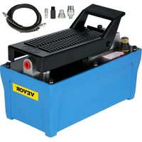
natural_image
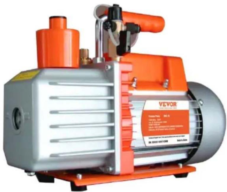
Exterior view of a Vevor vacuum pump with orange and silver casing (no visible text or symbols on the device body)NEED HELP? CONTACT US!
Have product questions? Need technical support? Please feel free to contact us:
Technical Support and E-Warranty Certificate
www.vevor.com/support
This is the original instruction, please read all manual instructions carefully before operating. VEVOR reserves a clear interpretation of o user manual. The appearance of the product shall be subject to the product you received. Please forgive us that we won't inform you ag there are any technology or software updates on our product.
INTRODUCTION
Welcome to the user manual for your vacuum pump. This vacuum put a versatile tool that can be used in a wide range of applications. It's particularly well-suited for tasks like HVAC vacuuming, epoxy and silico degassing, wood stabilization, and creating milking machines. Additionally this pump is also commonly used in medical appliances, printing machinery, vacuum packing, gas analysis, and hot-forming plastics. Its powerful and reliable performance makes it a valuable tool for professionals and DIY enthusiasts alike.
The vacuum pump works by creating a vacuum or negative pressure, which is used to remove air and other gases from an enclosed space process can be used for a range of purposes, including reducing air bubbles in resins or other liquids, evacuating HVAC systems, stabilizing wood by removing air from its cells, and many others.
This user manual is designed to help you understand how to operate maintain your vacuum pump effectively and safely. We will explain the features and components of the pump. Additionally, we will provide important safety guidelines to help you avoid potential hazards and er the proper handling of your vacuum pump.
Please read this user manual carefully before operating your vacuum pump. With proper use and maintenance, your vacuum pump can pro you with years of reliable service and help you achieve your desired If you have any questions or concerns about the operation of your v pump, please consult this manual or contact our customer support tea assistance.
Warning about potential hazards and how to avoid them
Your vacuum pump can pose potential hazards if it is not used prop. The most common hazards include electrical shock, fire, or explosion to pumping flammable, explosive or poisonous gases, or gases that can corrode metals and exert chemical charges. To avoid these hazards, always read and follow the instructions in this manual carefully before using your vacuum pump.
Instructions on how to handle the vacuum pump safely
To ensure the safe handling of your vacuum pump, please follow the guidelines:
◆ Never operate the pump without oil, as this can damage the pump create potential hazards.
◆ The temperature of the pumped gas should not exceed 80^ C, and environment temperature should be around 5^ C to 60^ C. This will prevent damage to the pump and ensure safe operation.
◆ Do not use the vacuum pump as a compression pump or convey pump, as this can cause damage to the pump and create potential hazards.
◆ The operating voltage for the pump is between 192 to 248V, 50H; Use a grounded outlet to prevent electrical shock.
When unplugging the pump, pull the plug. Do not unplug the unit pulling on the wire, as this can cause damage to the cord and potential hazards.
◆ Keep the electrical cord free from all shop equipment, and do not let the pump hang by the power cord to avoid damage to the cord prevent potential hazards.
◆ Do not use a damaged plug or outlet, as this can cause electrical shock or fire.
◆ Do not plug or unplug the unit with wet hands, as this can cause electrical shock.
◆ Do not plug the unit in, unplug it, or use the switch if there are flammable or explosive gases present. Always unplug the unit before disassembling it to avoid potential hazards.
Guidelines for handling hazardous materials
Your vacuum pump should not be used to pump flammable, explosive poisonous gases, or gases that can corrode metals and exert chemical charges. Additionally, do not pump gas containing any dust or moisture you need to handle hazardous materials, use proper personal protective equipment and follow all guidelines for safe handling and disposal of materials.
GETTING STARTED
Introducing the key features of the pump
◆ Dual-stage Rotary Vane Vacuum Pump with Gas Ballast:
The vacuum pump features a dual-stage rotary vane design with ballast. This feature reduces moisture corrosion of the machine an extends the life of the machine and oil.
◆ Copper Coil, Four-Pole Motor:
The pump is equipped with a copper coil and four-pole motor, with provides bigger torque for better starting and produces less heat, making it more durable.
◆ Die-Cut Aluminum Body and Ventilation Fan:
The vacuum pump features a die-cut aluminum body and a ventilator fan, which allows for easy heat dissipation and guarantees the performance stability of the pump.
◆ Anti-Flow Design:
The vacuum pump is designed with an auto anti-backflow valve a manual ball valve, which prevents backflow and allows for control the vacuum, preventing potential damage to the equipment.
Package contents and specification
| Model | 2KQ-2G | 2KQ-3G | |
| Voltage | 120V/60Hz | 120V/60Hz | |
| Free Air Displacement | CFM | 5 | 7 |
| Ultimate Vacuum | Pa | 8 | 8 |
| Motor | HP | 1/3 | 12 |
| Intake Fitting | 1/4"SAE male;3/8"SAE male;1/2"ACME male; | 1/4"SAE male;3/8"SAE male;1/2"ACME male;; | |
| Oil Cpacity | ml | 280 | 340 |
| Dimensions | mm | 320*125*230 | 335*125*250 |
| Net Weight | Kg | 8.6 | 10.4 |
| Applicable Refrigerant | R134a, R22, R410A, and any other A1 refrigerant | ||
Package list
| 2KQ-2G | 2KQ-3G |
| 5 CFM vacuum pump x 1280ml oil bottle x 1User manual x 1 | 7CFM vacuum pump x 1250ml oil bottle x 2User manual x 1 |
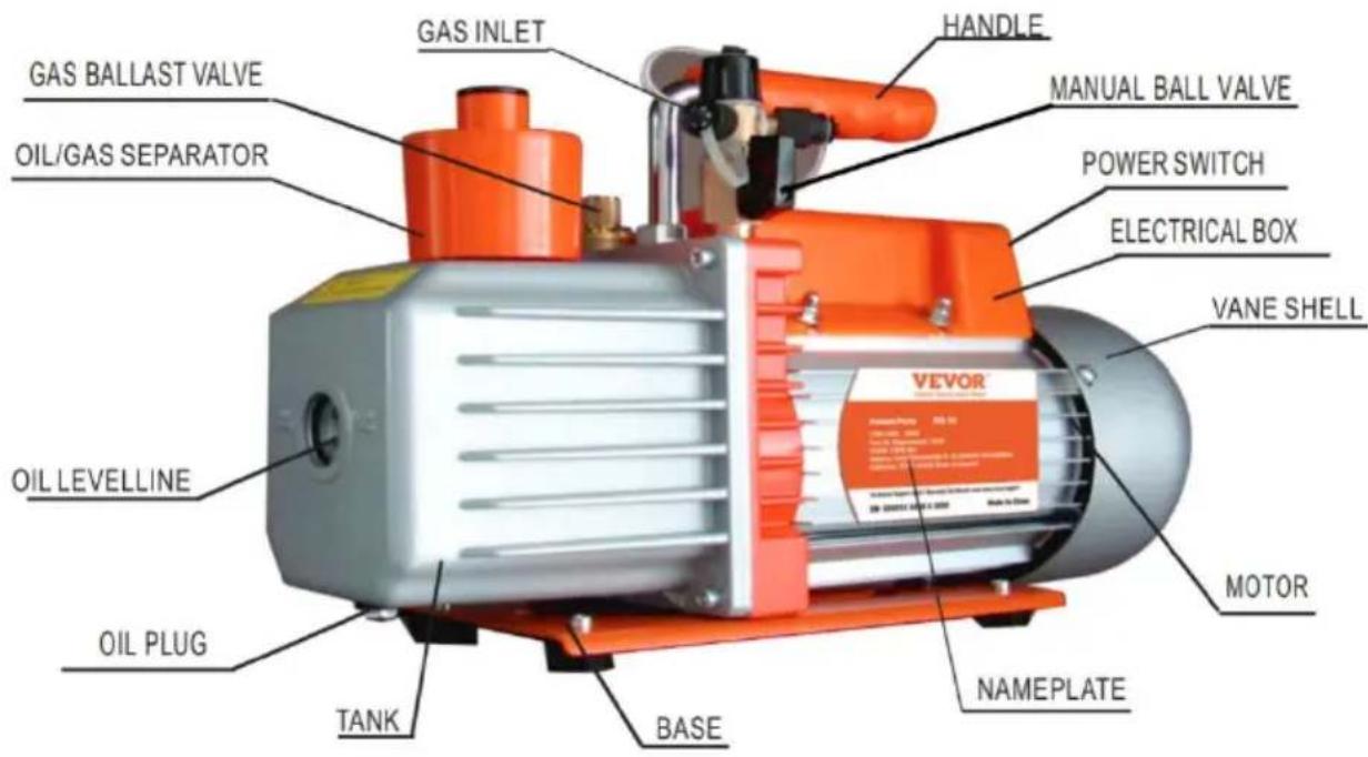
Explanation of the vacuum pump's components
Steps for setting up the vacuum pump
Following these steps will help you set up your vacuum pump correct ensure its safe and efficient operation.
Before use, remove the oil filling port/oil gas separator and fill it with the recommended vacuum pump oil. Check the oil level before us to ensure it's not lower than the oil-level line. Do not run the put a low oil level.
◆ Connect the container to be pumped to the gas inlet using a sho sealed hose that's free of dust, dirt, and heavy condensation. Che for leaks before operating the pump.
◆ If your vacuum pump comes with an exhaust cap, remove it.
◆ Plug in the power supply and turn on the switch.
◆ After use, unplug the vacuum pump, remove the connecting hoses, and cover the exhaust cap (if it has one) to prevent oil spills. A cover the oil plug to keep the oil clean and prevent dirt from er the vacuum pump.
Installation
To ensure the proper functioning of the vacuum pump, follow these installation guidelines:
◆ The pump should be positioned horizontally and in a dry, ventilated area free of dust and other contaminants.
◆ Maintain a clearance of at least 10cm (4 inches) around the pump ensure proper airflow.
◆ If you are permanently mounting the pump, remove the rubber pad from the bottom of the base, and use the existing threaded holes mount the unit with ST4.2 screws.
When permanently mounting the pump, be sure to maintain proper clearances, especially at the air intake at the end of the vane sh
◆ If a special electromagnetic valve is needed, it can be installed or gas inlet.
Connecting the vacuum pump to the system being evacuated By following these guidelines and steps, you can effectively control the vacuum pressure and safely connect the vacuum pump to the system being evacuated.
◆ Identify the gas inlet on the vacuum pump and the gas outlet on system being evacuated.
◆ Use a short, sealed hose to connect the gas inlet on the vacuum to the gas outlet on the system being evacuated. Make sure the is free of dust, dirt, and heavy condensation.
◆ Check for any leaks in the connection before starting the pump.
Maintenance
Proper maintenance of the vacuum pump is essential to ensure its performance. Here are some maintenance guidelines:
◆ Keep the pump clean and free from foreign matter.
◆ Keep the oil filled to the oil level, and never let the pump run w oil.
◆ Keep the oil clean. If the oil becomes dirty, muddy, or water or volatile substances get in, it will affect the performance of the pump and the oil should be replaced. To replace the oil, start the pump run it for about 30 minutes to make the oil thin. Then stop the and drain the oil from the oil drain plug. Open the gas inlet and pump for 1-2 minutes while adding a small quantity of clean oil in gas inlet. This is to replace the residual oil from the inside of the After ensuring that the pump is clean, put the drain plug back in the clean pump oil from the gas inlet to the oil level.
◆ To store the pump when not in use for long periods of time, cow oil cap and exhaust cap (if applicable) and store it in a dry plac
◆ Repair of the pump should only be done by a qualified service technician.
TROUBLESHOOTING GUIDE
| Problem | Possible Cause | Correction |
| Low Degree Of Vacuum | 1. Insufficient oil | 1. Add oil up to the oil level |
| 2. Dirty oil | 2. Replace the oil | |
| 3. Oil intake is blocked | 3. Clean the oil intake or filt | |
| 4. Hose or gas inlet is clogg | 4. Check the connecting pipe | |
| 5. Pump is unsuitable for the application | 5. Get a suitable pump for t application | |
| Oil Leaks | 1. Oil seal is damaged | 1. Replace the oil seal |
| 2. Housing gasket is loose o worn out | 2. Replace the housing gaske | |
| Oil Spray | 1. Too much oil | 1. Adjust the oil level to the recommended level |
| 2. Gas inlet pressure is too or too much gas has been pumped | 2. Use a bigger pump or reg gas inlet pressure | |
| Starting Difficulty | 1. Oil temperature is too low | 1. Attempt to start the pump multiple times to warm the oil |
EXPLODED DIAGRAM OF THE PUMP
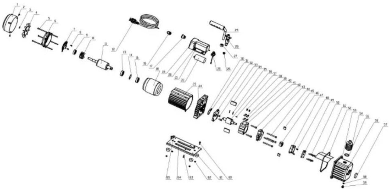
| 1 | Fan cover | 24 | Bracket | 47 | Back-pump stator |
| 2 | Screw | 25 | Gas ballast fitting | 48 | Screw |
| 3 | Snap ring | 26 | Screener | 49 | Back-pump cover |
| 4 | Fan | 27 | Nut | 50 | Screw |
| 5 | Screw | 28 | Gas inlet | 51 | Cap board |
| 6 | Motor back cover | 29 | Handle | 52 | O-ring |
| 7 | Centrifugal baseplate | 30 | O-ring | 53 | Screw |
| 8 | Screw | 31 | O-ring | 54 | Oil gas separator |
| 9 | Bearing | 32 | Front-pump stator | 55 | O-ring |
| 10 | Centrifugal | 33 | Screw | 56 | Oil tank |
| 11 | Motor rotor components | 34 | Front-pump vane | 57 | Oil level |
| 12 | Power cable | 35 | Spring | 58 | O-ring |
| 13 | Bearing | 36 | Front-pump rotor | 59 | Oil drain plug |
| 14 | Waveform gasket | 37 | Straight pin | 60 | Screw |
| 15 | Bearing | 38 | Screw | 61 | Rubber feet |
| 16 | Insulating bushing | 39 | Valve platen | 62 | Nut |
| 17 | Power Switch | 40 | Exhaust valve plate | 63 | Screw |
| 18 | Motor stator components | 41 | Front-pump stator | 64 | Baseboard |
| 19 | Junction box base | 42 | Screw | 65 | Rubber pad |
| 20 | Screw 43 | Intermediate connecting block | ||
| 21 | Gasket 44 Screw | |||
| 22 | Capacitor 45 Back-pump vane | |||
| 23 | Motor cover 46 Back-pump rotor |
VEVOR®
TOUGH TOOLS, HALF PRICE
Technical Support and E-Warranty Certificate
www.vevor.com/support
VEVOR®
TOUGH TOOLS, HALF PRICE
natural_image
Exterior view of a Vevor vacuum pump with orange and silver casing (no visible text or symbols)BESOIN D'AIDE? CONTACTEZ-NOUS!
Machine Translated by Google
natural_image
Exterior view of a Vevor vacuum pump with orange and silver casing (no visible text or symbols)Machine Translated by Google
www.vevor.com/support
VEVOR®
TOUGH TOOLS, HALF PRICE
natural_image
Exterior view of a Vevor vacuum pump with orange and silver casing (no visible text or symbols on the device body)Machine Translated by Google
elettronica www.vevor.com/support
VEVOR®
TOUGH TOOLS, HALF PRICE
natural_image
Exterior view of a Vevor vacuum pump with orange and silver casing (no visible text or symbols)www.vevor.com/support
Machine Translated by Google
natural_image
Exterior view of a Vevor vacuum pump with orange and silver casing (no visible text or symbols)POTRZEBUJESZ POMOCY? SKONTAKTUJ SIĘ Z NAMI!
Machine Translated by Google
natural_image
Exterior view of a Vevor vacuum pump with orange and silver casing (no visible text or symbols)HULP NODIG? NEEM CONTACT MET ONS OP!
www.vevor.com/support
HANDLEIDING VOOR PROBLEEMOPLOSSING
Machine Translated by Google
| 20 Schroef | 43 | Tussenliggende verbindingblok | ||
| 21 | Pakking | 44 | Schroef | |
| 22 | Condensator | 45 | Terugpomp schoep | |
| 23 | Motorkap | 46 | Terugpomprotor | |
VEVOR®
TOUGH TOOLS, HALF PRICE
garantiecertificaat www.vevor.com/support
VEVOR®
TOUGH TOOLS, HALF PRICE
natural_image
Exterior view of a Vevor vacuum pump with orange and silver casing (no visible text or symbols)BEHÖVER HJÄLP? KONTAKTA OSS!
| 1 | Fläktkåpa | 24 | Konsol | 47 | Stator med bakpump |
| 2 | Skruva | 25 | Gasballastkoppling | 48 | Skruva |
| 3 | Snäppring | 26 | Screener | 49 | Kåpa till backpumpen |
| 4 | Fläkt | 27 | Mutter | 50 | Skruva |
| 5 | Skruva | 28 | Gasinlopp | 51 | Kepsbräda |
| 6 | Motor bakstycke | 29 | Hantera | 52 | O-ring |
| 7 | Centrifugal bottenplatta | 30 | O-ring | 53 | Skruva |
| 8 | Skruva | 31 | O-ring | 54 | Oljegasavskiljare |
| 9 | Lager | 32 | Främre pumpstator | 55 | O-ring |
| 10 | Centrifugal | 33 | Skruva | 56 | Oljetank |
| 11 | Motorrotorkomponenter 34 | Främre pumpvinge | 57 | Oljenivå | |
| 12 | Strömkabel | 35 | Fjädra | 58 | O-ring |
| 13 | Lager | 36 | Främre pumprotor | 59 | Oljeavtappningsplugg |
| 14 | Vågformspackning Rak stift | 37 | 60 | Skruva | |
| 15 | Lager | 38 | Skruva | 61 | Gummifötter |
| 16 | Isolerande bussning | 39 | Ventilplattor | 62 | Mutter |
| 17 | Strömbrytare | 40 | Avgasventilplatta | 63 | Skruva |
| 18 | Motorstatorkomponenter 41 | Främre pumpstator | 64 | Bastavla | |
| 19 | Kopplingsdosa bas | 42 | Skruva | 65 | Gummikudde |
Machine Translated by Google
| 20 | Skruva | 43 | Mellankopplingblockera | |
| 21 | Packning | 44 | Skruva | |
| 22 | Kondensator | 45 | Back-pump skovel | |
| 23 | Motorkåpa | 46 | Backpumpsrotor |
VEVOR®
TOUGH TOOLS, HALF PRICE
www.vevor.com/support