TW-1K - Pump Vevor - Free user manual and instructions
Find the device manual for free TW-1K Vevor in PDF.

| Brand | Vevor |
| Model | KQ-1K (TW-1K) |
| Product Type | Vacuum Pump and Chamber Kit |
| Power Supply | 120 V/60 Hz or 220-240 V/50 Hz |
| Free Air Displacement | 3.5 CFM |
| Ultimate Vacuum | 8 Pa (8 microns) |
| Motor | 1/5 HP |
| Intake Connection | 1/4" SAE male |
| Oil Capacity | 250 ml |
| Dimensions (L x W x H) | 290 x 120 x 220 mm |
| Net Weight | 5.5 kg |
| Kit Contents | Vacuum pump, vacuum chamber (3 or 5 gallons), charging hose, tempered glass lid, vacuum gauge, muffler, silicone cushion, oil, manual |
| Main Functions | Degassing of silicone, resin, gypsum; impregnation of wood and porous materials |
| Operating Temperature | +5 °C to +40 °C (ambient); pumped gas up to 80 °C |
| Ambient Humidity | Up to 80% at 20 °C |
| Maintenance | Check and replace oil if dirty; clean oil intake and filter; drain oil after 30 min of operation |
| Safety | Do not use with flammable/explosive gases; avoid electric shock; do not pump above atmospheric pressure; use gloves and goggles |
| Spare Parts | Oil seal, housing gasket, oil filter, specific oil |
| Repairability | Repair only by qualified technician |
| Warranty | Electronic warranty certificate available at www.vevor.com/support |
| Standards | European Directive 2012/19/EU (WEEE) |
Frequently Asked Questions - TW-1K Vevor
User questions about TW-1K Vevor
0 question about this device. Answer the ones you know or ask your own.
Ask a new question about this device
Download the instructions for your Pump in PDF format for free! Find your manual TW-1K - Vevor and take your electronic device back in hand. On this page are published all the documents necessary for the use of your device. TW-1K by Vevor.
USER MANUAL TW-1K Vevor
Technical Support and E-Warranty Certificate www.vevor.com/support
VACUUM PUMP AND CHAMBER KIT OPERATING MANUAL
We continue to be committed to provide you tools with competitive price. "Save Half", "Half Price" or any other similar expressions used by us only represents an estimate of savings you might benefit from buying certain tools with us compared to the major top brands and does not necessarily mean to cover all categories of tools offered by us. You are kindly reminded to verify carefully when you are placing an order with us if you are actually saving half in comparison with the top major brands
VEVOR®
TOUGH TOOLS, HALF PRICE
VACUUM PUMP AND
CHAMBER KIT
PUMP MODEL: KQ-1K

natural_image
Product photo of Vevor air purifier and cleaning equipment including pump, hose, and tools (no visible text or symbols)CE
NEED HELP? CONTACT US!
Have product questions? Need technical support? Please feel free to contact us:
Technical Support and E-Warranty Certificate www.vevor.com/support
This is the original instruction, please read all manual instructions carefully before operating. VEVOR reserves a clear interpretation of o user manual. The appearance of the product shall be subject to the product you received. Please forgive us that we won't inform you ag there are any technology or software updates on our product.
This product is subject to the provision of European Directive 2012/19/EU. The symbol showing a wheelie bin crossed through indicates that the product requires separate refuse collection in European Union. This applies to the product and all accessories marked with this symbol. Products marked as such may not be discawith normal domestic waste but must be taken to a collection point 1 recycling electrical and electronic devices.
INTRODUCTION
Thank you for choosing our vacuum pump and chamber kit. Our vacuum pump and chamber kit is an essential tool kit used in various applications including degassing casting materials such as silicone, resin, gypsum, impregnation of wood and other porous materials. This product is designed to create a low-pressure environment by the suction of contained gases, the vacuum pump inside a sealed vacuum chamber.
The vacuum chamber in this kit is a specially designed sealed tank can create a low-pressure environment to facilitate the degassing and impregnation processes. With this kit, you can achieve high-quality cas or impregnation results, ensuring that your materials are free of bubble and other impurities.
This vacuum pump and chamber kit is designed to operate under spot conditions. It can be operated in ambient temperatures ranging between +5°C and +40°C and air humidity up to 80% at 20°C. These operating conditions ensure that the equipment performs optimally and guarantees the desired results.
In the following sections of this manual, you will find detailed instruction on how to set up, operate, and maintain your vacuum pump and cha kit, ensuring that you can achieve the best possible results for your applications.
The warnings, precautions, and instructions provided in this manual ca cover all possible situations that may occur. It is the operator's responsibility to exercise common sense and caution while using the equipment.
Safety guidelines for handling your vacuum pump
Electrical shock hazard: Do not touch the vacuum pump with wet hands or while standing on a wet surface. Always use the vacuum pump in a dry environment and plug it into a properly grounded
◆ Fire hazard: Do not use the vacuum pump near flammable or combustible materials. Keep the pump away from sources of heat sparks, such as flames, cigarettes, or electrical appliances.
◆ Explosion hazard: Do not use the vacuum pump with gases that a flammable, explosive, or poisonous. Always check the safety data sheet (SDS) of the gas before using it with the vacuum pump. Additionally, do not exceed the specified pressure range for the p
Corrosion hazard: Do not use the vacuum pump with gases that can corrode metals or cause chemical reactions. Check the compatibility the gas with the materials of the pump and its accessories. Always protective gloves and eyewear when handling corrosive materials.
◆ Never operate the pump without oil, as this can damage the pump create potential hazards.
The temperature of the gas being pumped should not exceed 80^ C, and the environmental temperature should be between 5^ C and 60^ C to prevent damage to the pump and ensure safe operation.
When unplugging the pump, always pull the plug. Do not unplug the unit by pulling on the wire, as this can damage the cord and create potential hazards.
◆ Do not use a damaged plug or outlet, as this can cause electrical shock or fire.
Safety guidelines for using the vacuum pump and chamber kit
Pressure and Explosion Risk:
- Do not pump the vacuum chamber or increase pressure inside the tank higher than atmospheric pressure, as this can lead to an explosion.
Weight and Lid Placement:
- Do not put any additional weight on the lid of the chamber.
- The lid must be properly placed on the tank.
- The gasket must not extend beyond the outline of the lid, as this lead to a sudden unsealing of the chamber.
Damage and Maintenance:
- Exclude any lid, gasket, or tank from use if it has any cracking, deformation, or other mechanical damage.
- Perform servicing and maintenance of the vacuum kit periodically.
- Check the technical condition of the vacuum set before each use.
Environmental and Chemical Safety:
- Keep hard or heavy objects away from the vacuum chamber.
- Do not place live organisms in vacuum tanks.
- Do not subject any parts of the human body to under-pressure.
- Avoid excessive pollution of the working environment by dust, power small solids, or water, as heavy contamination can damage the power
- Ensure that the chemicals used do not damage the vacuum set.
Operating Safety:
- Do not directly power off the pump before closing the valve conr to the chamber. This may damage the pump or cause oil backflo spray.
-
Do not assemble or disassemble individual parts of the vacuum s while the vacuum pump is operating or if the vacuum setting is vacuum.
-
Never put fingers or other objects inside the pump impeller cover. Keep your hair, clothing, gloves, and other objects that could get the impeller away from moving parts.
- Do not expose the device to rain or excessive moisture.
- Do not leave the vacuum set unattended during operation.
- Keep children, people with disabilities, and animals away from the operating area of the device.
- Be foreseeable, watch what you are doing, and be reasonable while using the device.
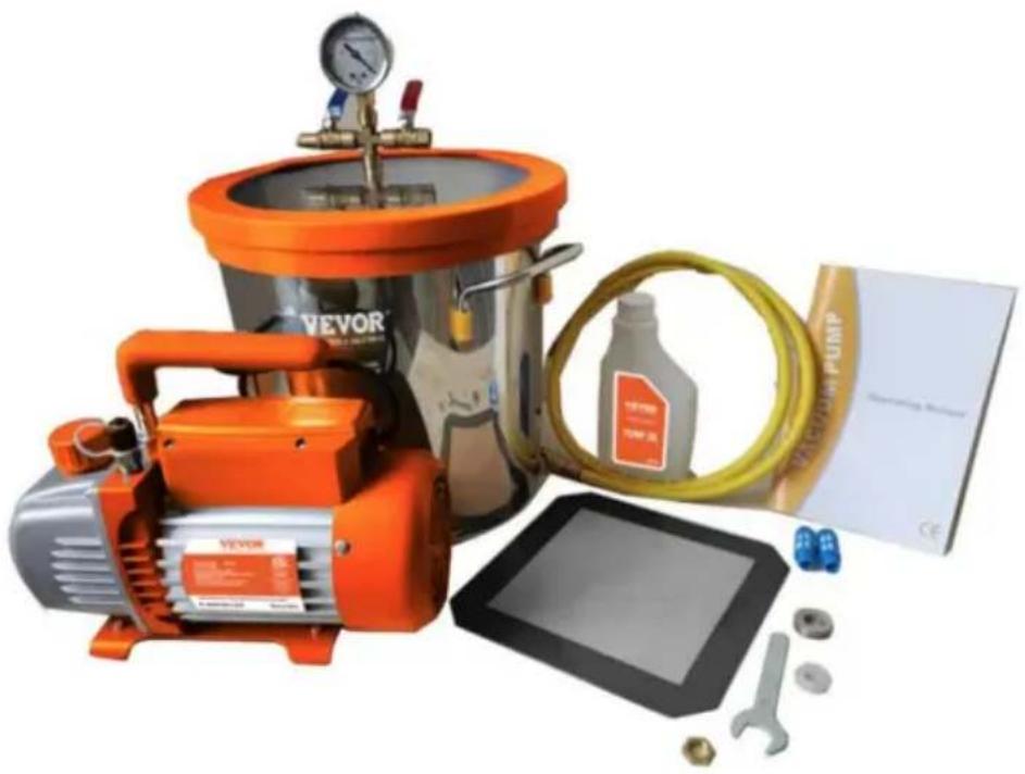
Vacuum pump and Chamber Kit package contents
| Model | KQ-1K | ||
| Voltage | 120V/60Hz | 220-240V/50Hz | |
| Free Air Displacement | CFM | 3.5 | 3.5 |
| Ultimate Vacuum | Pa | 8 | 8 |
| Motor | HP | 1/5 | 1/5 |
| Intake Fitting | 1/4"SAE male; | 1/4"SAE male; | |
| Oil Capacity | ml | 250 | 250 |
| Dimensions | mm | 290*120*220 | 290*120*220 |
| Net Weight | Kg | 5.5 | 5.4 |
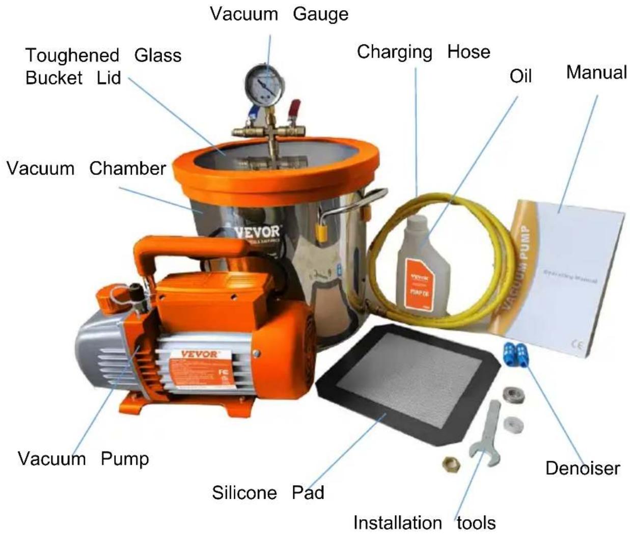
Package Content List
| Set Name | 3.5 CFM Vacuum Pump & Gallon Vacuum Chamber Set | 3.5CFM Vacuum Pump & 5 Gal Vacuum Chamber Set |
| Packing List | Vacuum Pumpx13 Gallon Vacuum Chamberx1Charging Hosex1Toughened Glass Bucket Lidx1Vacuum Gaugex1Denoiserx2Silicone Padx1Vacuum Pump Oilx1Manualx1 | Vacuum Pumpx15 Gallon Vacuum Chamberx1Charging Hosex1Toughened Glass Bucket Lidx1Vacuum Gaugex1Denoiserx2Silicone Padx1Vacuum Pump Oilx1Manualx1 |
Installation of vacuum pump and chamber kit
| 1 | Check the parts: Before starting the installation process, make sure you have all the necessary parts to install the chamber lid and connect it vacuum pump. | 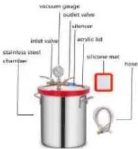 |
| 2 | Insert the valve: Take the tempered glass lid locate the hole where the valve needs to be inserted. Insert the valve into the hole, making it fits snugly and is secure. | 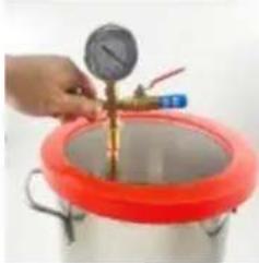 |
| 3 | Install the washer and nut: Place the washer the valve, and then screw the nut onto the v threads. Tighten the nut by hand until it is sn | 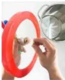 |
| 4 | Connect the hose: Take one end of the hose connect it to the valve on the glass lid. Make the connection is tight and secure. Then, take other end of the hose and connect it to the of the vacuum pump. Again, make sure the connection is tight and secure. | 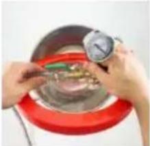 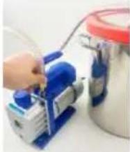 |
| 5 | Turn off the outlet valve as indicated, turn on the inlet valve, and the chamber is ready for use. |  |
Pulling vacuum and vacuum treatment
- Prepare the Item for treatment: Before beginning the procedure, prepare the item by stabilizing it or removing any excess moisture dust, or debris.
- Place the Item in the Chamber: Put the item to be treated in the vacuum chamber, ensuring that it is positioned in the center and doesn't touch the sides or lid. It is recommended to place a silic mat at the bottom when degassing to prevent pouring liquid from spilling.
- Seal the Chamber: Make sure that the lid is properly aligned with vacuum chamber and that the gasket is clean and free from deb
- Start the Vacuum Pump: Turn on the vacuum pump and set the desired vacuum pressure based on your requirements.
- Monitor the Vacuum Pressure: Keep an eye on the vacuum press throughout the process. If it drops, check for leaks in the chamber hoses.
- Stop the Vacuum Pump: When the stabilization process is complete, turn off the vacuum pump. Wait for the vacuum pressure to return atmospheric pressure before opening the chamber.
- If multiple cycles of vacuuming are needed, slowly open the inlet to let the chamber return to atmospheric pressure, then close the and repeat the process.
- Remove the Item: After the vacuum pressure returns to atmosphere pressure, carefully remove the item from the vacuum chamber.
- Disconnect the Vacuum Pump: Disconnect the vacuum pump from chamber and hoses and properly store the equipment as per the instructions provided in the user manual.
-
Clean the Chamber: After use, thoroughly clean the vacuum chair and hoses to ensure that they are free from debris and moisture Attention:
-
When placing the tempered glass lid, ensure that it is position correctly without any deflection. If the lid is slightly inclined, the vacuum chamber may not hold a vacuum, and the lid may be
sucked into the chamber with pressure.
- If the pointer of the vacuum gauge is not in the null position cannot pull the vacuum to the maximum, open the black cover the gauge top and calibrate the pointer to normal.
- After vacuuming, slowly turn on the outlet valve to prevent damage to the vacuum gauge.
Proper maintenance of the vacuum pump is essential to ensure its performance. Here are some maintenance guidelines:
◆ Keep the pump clean and free from foreign matter.
◆ Keep the oil filled to the oil level, and never let the pump run w oil.
◆ Keep the oil clean. If the oil becomes dirty, muddy, or water or volatile substances get in, it will affect the performance of the pump and the oil should be replaced. To replace the oil, start the pump run it for about 30 minutes to make the oil thin. Then stop the and drain the oil from the oil drain plug. Open the gas inlet and pump for 1-2 minutes while adding a small quantity of clean oil in gas inlet. This is to replace the residual oil from the inside of the After ensuring that the pump is clean, put the drain plug back in the clean pump oil from the gas inlet to the oil level.
◆ To store the pump when not in use for long periods of time, cow oil cap and exhaust cap (if applicable) and store it in a dry plac
◆ Repair of the pump should only be done by a qualified service technician.
| Problem | Possible Cause | Correction |
| Low Degree Of Vacuum | 1.Insufficient oil | 1.Add oil up to the oil level line |
| 2.Dirty oil | 2.Replace the oil | |
| 3.Oil intake is blocked | 3.Clean the oil intake or filter | |
| 4.Hose or gas inlet is clogged | 4.Check the connecting pipes | |
| 5.Pump is unsuitable for the application | 5.Get a suitable pump for the application | |
| Oil Leaks | 1.Oil seal is damaged | 1.Replace the oil seal |
| 2.Housing gasket is loose or worn | 2.Replace the housing gasket | |
| Oil Spray | 1.Too much oil | 1.Adjust the oil level to the recommended l |
| 2.Gas inlet pressure is too high or much gas has been pumped | 2.Use a bigger pump or reduce gas inlet pressure | |
| Starting Difficulty | 1.Oil temperature is too low | 1.Attempt to start the pump multiple times t warm the oil |
| 2.Electrical malfunction | 2.Check and repair any electrical issues | |
| 3.Foreign matter is in the pump | 3.Check and remove any foreign matter from pump system | |
| Failure To Pull a Good Vacuum | Leakage in vacuum gauge or connections | Confirm leakage by monitoring the vacuum gauge while applying vacuum pump oil at a connections or suspected leak points. The vacuum will improve briefly while the oil is sealing the leak. |
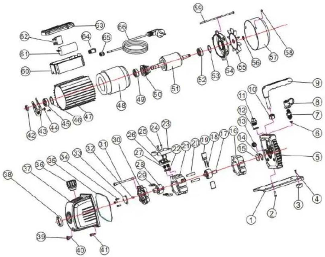
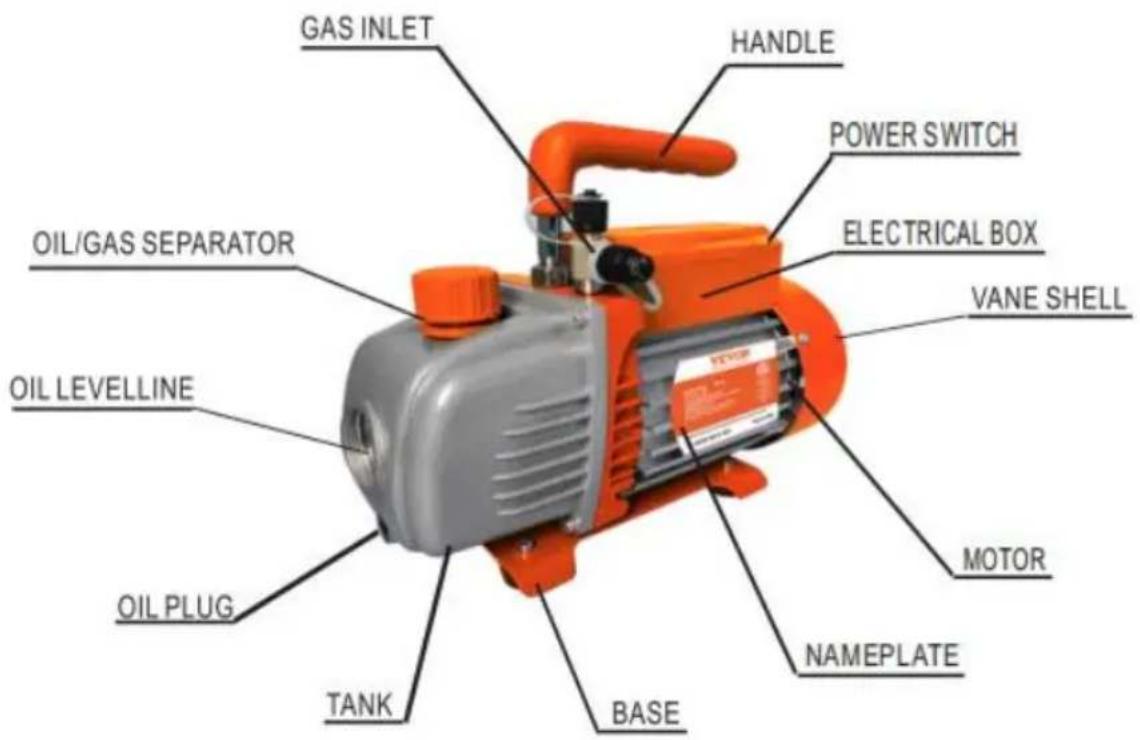
| 01 | Baseboard | 18 | Spring | 35 | O-ring | 52 | Bearing |
| 02 | Screw | 19 | Front-pump vane | 36 | Oil gas separator | 53 | Waveform gasket |
| 03 | Rubber feet | 20 | Straight pin | 37 | Oil tank | 54 | Motor back cover |
| 04 | Screw | 21 | Back-pump stator | 38 | Oil level | 55 | Fan |
| 05 | Bracket | 22 | Exhaust valve core | 39 | Oil drain plug | 56 | Snap ring |
| 06 | Stainer | 23 | Cap board | 40 | O-ring | 57 | Fan cover |
| 07 | Inlet fitting | 24 | Screw | 41 | Screw | 58 | Screw |
| 08 | Inlet fitting cap | 25 | Screw | 42 | Oil seal | 59 | Screw |
| 09 | Handle | 26 | Valve set | 43 | Centrifugal plate | 60 | Junction box base |
| 10 | Nut | 27 | Valve core spring | 44 | Screw | 61 | Capacitor |
| 11 | Oil filling port | 28 | Back-pump rotor | 45 | Bearing | 62 | Thermal protector |
| 12 | O-ring | 29 | Back-pump vane | 46 | Bearing gasket | 63 | Junction box cover |
| 13 | Gas ballast fitting | 30 | Back cover | 47 | Motor cover | 64 | Switch |
| 14 | O-ring | 31 | Screw | 48 | Motor stator components | 65 | ply-yarn drill |
| 15 | O-ring | 32 | Oil pump vane | 49 | Bearing | 66 | Power cable |
| 16 | Front-pump stator | 33 | Oil pump cover | 50 | Centrifugal | ||
| 17 | Front-pump rotor | 34 | Screw | 51 | Motor rotor components |
VEVOR®
TOUGH TOOLS, HALF PRICE
Technical Support and E-Warranty Certificate www.vevor.com/support
VEVOR®
TOUGH TOOLS, HALF PRICE
natural_image
Product photo of an electric shock absorber with visible components including pump, hose, and electronic devices (no text or symbols)CE
BESOIN D'AIDE? CONTACTEZ-NOUS!
| 01 | Baseboard | 18 | Spring | 35 | O-ring | 52 | Bearing |
| 02 | Screw | 19 | Front-pump vane | 36 | Oil gas separator | 53 | Waveform gasket |
| 03 | Rubber feet | 20 | Straight pin | 37 | Oil tank | 54 | Motor back cover |
| 04 | Screw | 21 | Back-pump stator | 38 | Oil level | 55 | Fan |
| 05 | Bracket | 22 | Exhaust valve core | 39 | Oil drain plug | 56 | Snap ring |
| 06 | Stainer | 23 | Cap board | 40 | O-ring | 57 | Fan cover |
| 07 | Inlet fitting | 24 | Screw | 41 | Screw | 58 | Screw |
| 08 | Inlet fitting cap | 25 | Screw | 42 | Oil seal | 59 | Screw |
| 09 | Handle | 26 | Valve set | 43 | Centrifugal plate | 60 | Junction box base |
| 10 | Nut | 27 | Valve core spring | 44 | Screw | 61 | Capacitor |
| 11 | Oil filling port | 28 | Back-pump rotor | 45 | Bearing | 62 | Thermal protector |
| 12 | O-ring | 29 | Back-pump vane | 46 | Bearing gasket | 63 | Junction box cover |
| 13 | Gas ballast fitting | 30 | Back cover | 47 | Motor cover | 64 | Switch |
| 14 | O-ring | 31 | Screw | 48 | Motor stator components | 65 | ply-yarn drill |
| 15 | O-ring | 32 | Oil pump vane | 49 | Bearing | 66 | Power cable |
| 16 | Front-pump stator | 33 | Oil pump cover | 50 | Centrifugal | ||
| 17 | Front-pump rotor | 34 | Screw | 51 | Motor rotor components |
VEVOR®
TOUGH TOOLS, HALF PRICE
natural_image
Product photo of an electric shock absorber with orange air purifier, coiled hose, and electronic devices (no visible text or symbols)CE
| 01 | Baseboard | 18 | Spring | 35 | O-ring | 52 | Bearing |
| 02 | Screw | 19 | Front-pump vane | 36 | Oil gas separator | 53 | Waveform gasket |
| 03 | Rubber feet | 20 | Straight pin | 37 | Oil tank | 54 | Motor back cover |
| 04 | Screw | 21 | Back-pump stator | 38 | Oil level | 55 | Fan |
| 05 | Bracket | 22 | Exhaust valve core | 39 | Oil drain plug | 56 | Snap ring |
| 06 | Stainer | 23 | Cap board | 40 | O-ring | 57 | Fan cover |
| 07 | Inlet fitting | 24 | Screw | 41 | Screw | 58 | Screw |
| 08 | Inlet fitting cap | 25 | Screw | 42 | Oil seal | 59 | Screw |
| 09 | Handle | 26 | Valve set | 43 | Centrifugal plate | 60 | Junction box base |
| 10 | Nut | 27 | Valve core spring | 44 | Screw | 61 | Capacitor |
| 11 | Oil filling port | 28 | Back-pump rotor | 45 | Bearing | 62 | Thermal protector |
| 12 | O-ring | 29 | Back-pump vane | 46 | Bearing gasket | 63 | Junction box cover |
| 13 | Gas ballast fitting | 30 | Back cover | 47 | Motor cover | 64 | Switch |
| 14 | O-ring | 31 | Screw | 48 | Motor stator components | 65 | ply-yarn drill |
| 15 | O-ring | 32 | Oil pump vane | 49 | Bearing | 66 | Power cable |
| 16 | Front-pump stator | 33 | Oil pump cover | 50 | Centrifugal | ||
| 17 | Front-pump rotor | 34 | Screw | 51 | Motor rotor components |
VEVOR®
TOUGH TOOLS, HALF PRICE
MODELLO POMPA : KQ-1K
natural_image
Product photo of an electric shock absorber with orange air purifier, coiled hose, and electronic devices (no visible text or symbols)CE
www.vevor.com/support
| 01 | Baseboard | 18 | Spring | 35 | O-ring | 52 | Bearing |
| 02 | Screw | 19 | Front-pump vane | 36 | Oil gas separator | 53 | Waveform gasket |
| 03 | Rubber feet | 20 | Straight pin | 37 | Oil tank | 54 | Motor back cover |
| 04 | Screw | 21 | Back-pump stator | 38 | Oil level | 55 | Fan |
| 05 | Bracket | 22 | Exhaust valve core | 39 | Oil drain plug | 56 | Snap ring |
| 06 | Stainer | 23 | Cap board | 40 | O-ring | 57 | Fan cover |
| 07 | Inlet fitting | 24 | Screw | 41 | Screw | 58 | Screw |
| 08 | Inlet fitting cap | 25 | Screw | 42 | Oil seal | 59 | Screw |
| 09 | Handle | 26 | Valve set | 43 | Centrifugal plate | 60 | Junction box base |
| 10 | Nut | 27 | Valve core spring | 44 | Screw | 61 | Capacitor |
| 11 | Oil filling port | 28 | Back-pump rotor | 45 | Bearing | 62 | Thermal protector |
| 12 | O-ring | 29 | Back-pump vane | 46 | Bearing gasket | 63 | Junction box cover |
| 13 | Gas ballast fitting | 30 | Back cover | 47 | Motor cover | 64 | Switch |
| 14 | O-ring | 31 | Screw | 48 | Motor stator components | 65 | ply-yarn drill |
| 15 | O-ring | 32 | Oil pump vane | 49 | Bearing | 66 | Power cable |
| 16 | Front-pump stator | 33 | Oil pump cover | 50 | Centrifugal | ||
| 17 | Front-pump rotor | 34 | Screw | 51 | Motor rotor components |
VEVOR®
TOUGH TOOLS, HALF PRICE
natural_image
Product photo of an electric shock absorber with orange air purifier, coiled hose, and electronic devices (no visible text or symbols)CE
POTRZEBUJESZ POMOCY? SKONTAKTUJ SIĘ Z NAMI!
www.vevor.com/support
| 01 | Baseboard | 18 | Spring | 35 | O-ring | 52 | Bearing |
| 02 | Screw | 19 | Front-pump vane | 36 | Oil gas separator | 53 | Waveform gasket |
| 03 | Rubber feet | 20 | Straight pin | 37 | Oil tank | 54 | Motor back cover |
| 04 | Screw | 21 | Back-pump stator | 38 | Oil level | 55 | Fan |
| 05 | Bracket | 22 | Exhaust valve core | 39 | Oil drain plug | 56 | Snap ring |
| 06 | Stainer | 23 | Cap board | 40 | O-ring | 57 | Fan cover |
| 07 | Inlet fitting | 24 | Screw | 41 | Screw | 58 | Screw |
| 08 | Inlet fitting cap | 25 | Screw | 42 | Oil seal | 59 | Screw |
| 09 | Handle | 26 | Valve set | 43 | Centrifugal plate | 60 | Junction box base |
| 10 | Nut | 27 | Valve core spring | 44 | Screw | 61 | Capacitor |
| 11 | Oil filling port | 28 | Back-pump rotor | 45 | Bearing | 62 | Thermal protector |
| 12 | O-ring | 29 | Back-pump vane | 46 | Bearing gasket | 63 | Junction box cover |
| 13 | Gas ballast fitting | 30 | Back cover | 47 | Motor cover | 64 | Switch |
| 14 | O-ring | 31 | Screw | 48 | Motor stator components | 65 | ply-yarn drill |
| 15 | O-ring | 32 | Oil pump vane | 49 | Bearing | 66 | Power cable |
| 16 | Front-pump stator | 33 | Oil pump cover | 50 | Centrifugal | ||
| 17 | Front-pump rotor | 34 | Screw | 51 | Motor rotor components |
VEVOR®
TOUGH TOOLS, HALF PRICE
natural_image
Product photo of an electric shock absorber with orange air purifier, coiled hose, and electronic devices (no visible text or symbols)CE
HULP NODIG? NEEM CONTACT MET ONS OP!
www.vevor.com/support
HANDLEIDING VOOR PROBLEEMOPLOSSING
| 01 | Baseboard | 18 | Spring | 35 | O-ring | 52 | Bearing |
| 02 | Screw | 19 | Front-pump vane | 36 | Oil gas separator | 53 | Waveform gasket |
| 03 | Rubber feet | 20 | Straight pin | 37 | Oil tank | 54 | Motor back cover |
| 04 | Screw | 21 | Back-pump stator | 38 | Oil level | 55 | Fan |
| 05 | Bracket | 22 | Exhaust valve core | 39 | Oil drain plug | 56 | Snap ring |
| 06 | Stainer | 23 | Cap board | 40 | O-ring | 57 | Fan cover |
| 07 | Inlet fitting | 24 | Screw | 41 | Screw | 58 | Screw |
| 08 | Inlet fitting cap | 25 | Screw | 42 | Oil seal | 59 | Screw |
| 09 | Handle | 26 | Valve set | 43 | Centrifugal plate | 60 | Junction box base |
| 10 | Nut | 27 | Valve core spring | 44 | Screw | 61 | Capacitor |
| 11 | Oil filling port | 28 | Back-pump rotor | 45 | Bearing | 62 | Thermal protector |
| 12 | O-ring | 29 | Back-pump vane | 46 | Bearing gasket | 63 | Junction box cover |
| 13 | Gas ballast fitting | 30 | Back cover | 47 | Motor cover | 64 | Switch |
| 14 | O-ring | 31 | Screw | 48 | Motor stator components | 65 | ply-yarn drill |
| 15 | O-ring | 32 | Oil pump vane | 49 | Bearing | 66 | Power cable |
| 16 | Front-pump stator | 33 | Oil pump cover | 50 | Centrifugal | ||
| 17 | Front-pump rotor | 34 | Screw | 51 | Motor rotor components |
VEVOR®
TOUGH TOOLS, HALF PRICE
Technische ondersteuning en e- garantiecertificaat www.vevor.com/support
VEVOR®
TOUGH TOOLS, HALF PRICE
natural_image
Product photo of an electric shock absorber with orange air purifier, coiled hose, and electronic devices (no visible text or symbols)CE
BEHÖVER HJÄLP? KONTAKTA OSS!
| 01 | Baseboard | 18 | Spring | 35 | O-ring | 52 | Bearing |
| 02 | Screw | 19 | Front-pump vane | 36 | Oil gas separator | 53 | Waveform gasket |
| 03 | Rubber feet | 20 | Straight pin | 37 | Oil tank | 54 | Motor back cover |
| 04 | Screw | 21 | Back-pump stator | 38 | Oil level | 55 | Fan |
| 05 | Bracket | 22 | Exhaust valve core | 39 | Oil drain plug | 56 | Snap ring |
| 06 | Stainer | 23 | Cap board | 40 | O-ring | 57 | Fan cover |
| 07 | Inlet fitting | 24 | Screw | 41 | Screw | 58 | Screw |
| 08 | Inlet fitting cap | 25 | Screw | 42 | Oil seal | 59 | Screw |
| 09 | Handle | 26 | Valve set | 43 | Centrifugal plate | 60 | Junction box base |
| 10 | Nut | 27 | Valve core spring | 44 | Screw | 61 | Capacitor |
| 11 | Oil filling port | 28 | Back-pump rotor | 45 | Bearing | 62 | Thermal protector |
| 12 | O-ring | 29 | Back-pump vane | 46 | Bearing gasket | 63 | Junction box cover |
| 13 | Gas ballast fitting | 30 | Back cover | 47 | Motor cover | 64 | Switch |
| 14 | O-ring | 31 | Screw | 48 | Motor stator components | 65 | ply-yarn drill |
| 15 | O-ring | 32 | Oil pump vane | 49 | Bearing | 66 | Power cable |
| 16 | Front-pump stator | 33 | Oil pump cover | 50 | Centrifugal | ||
| 17 | Front-pump rotor | 34 | Screw | 51 | Motor rotor components |
VEVOR®
TOUGH TOOLS, HALF PRICE