JZ48V2000W - Electric motor Vevor - Free user manual and instructions
Find the device manual for free JZ48V2000W Vevor in PDF.

| Product Type | Brushless DC Electric Motor |
| Brand | Vevor |
| Model | JZ48V2000W |
| Rated Voltage | 48 V DC |
| Maximum Power | 2000 W |
| Rated Current | 35 A |
| Rated Speed | 4300 RPM |
| No-Load Speed | 5600 ± 10% RPM |
| Rated Torque | 4.8 Nm |
| Motor Efficiency | ≥ 85% |
| Motor Weight | 4.61 kg ± 5% |
| Motor Dimensions (L × W × H) | 134 × 107 × 112 mm |
| Number of Sprocket Teeth | T8F-9T and T8F-11T |
| Screw Thread | M8 × 1.25 × 12 mm (left-hand, with threadlocker) |
| Recommended Maximum Load | ≤ 150 kg |
| Recommended Reduction Ratio | 9 or 11 teeth: 64 teeth |
| Recommended Battery Type | Lead-acid or lithium (12-20 Ah, compatible voltage) |
| Controller Included | ZWK4835 (48 V, 2000 W, 35 A) |
| Controller Dimensions | 212 × 87 × 49 mm (± 2 mm) |
| Controller Weight | 0.63 kg |
| Operating Temperature Range | -25 °C to 60 °C |
| Undervoltage Threshold | 39 V |
| Application Areas | Small electric vehicles, bicycles, go-karts, scooters |
| Safety | Overload, undervoltage, short-circuit protection; low-level brake |
| Maintenance | Check connections, clean dust, store in a dry and ventilated place |
| Available Spare Parts | Motor, controller, wiring harnesses, accessories (handle, switch, etc.) |
Frequently Asked Questions - JZ48V2000W Vevor
User questions about JZ48V2000W Vevor
0 question about this device. Answer the ones you know or ask your own.
Ask a new question about this device
Download the instructions for your Electric motor in PDF format for free! Find your manual JZ48V2000W - Vevor and take your electronic device back in hand. On this page are published all the documents necessary for the use of your device. JZ48V2000W by Vevor.
USER MANUAL JZ48V2000W Vevor
Technical Support and E-Warranty Certificate www.vevor.com/support
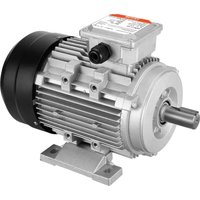
Brushless DC motor
Model: JZ48V2000W
We continue to be committed to provide you tools with competitive price "Save Half", "Half Price" or any other similar expressions used by us only repeat estimate of savings you might benefit from buying certain tools with us compared top brands and does not necessarily mean to cover all categories of tools offer are kindly reminded to verify carefully when you are placing an order with us actually saving half in comparison with the top major brands.
MODEL: JZ48V2000W
NEED HELP? CONTACT US!
Have product questions? Need technical support? Please feel fr contact us:
Technical Support and E-Warranty Certificate www.vevor.com/support
This is the original instruction, please read all manual instruction carefully before operating. VEVOR reserves a clear interpretation user manual. The appearance of the product shall be subject to product you received. Please forgive us that we won't inform y there are any technology or software updates on our product.

Safety precautions
1.1Safety advisory warning
Please read carefully before operation.
Be sure to read all safety warnings and all instructions before operating the Failure to comply with warnings and instructions may result in electric shock, serious injury.
If you encounter problems, please communicate with customer service in timesolve, your satisfaction is our service purpose.
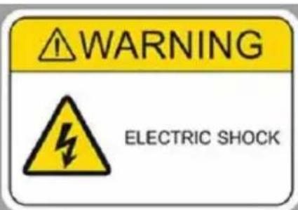
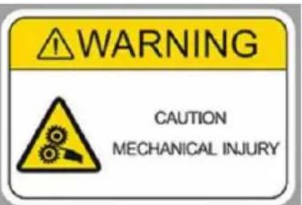
1.2 Warning sign for safe operation of motor

1.3 Risk factor
1) Mechanical damage
2) Get an electric shock
3) Extrusion collision
4) Object impact
5) Other injuries
1.4 Operational considerations and triggers for motor non-work accidents
1) Check whether all accessories are connected tightly and not loose, check whether the pins in each plug-in are bent, and visually check whether each interface is consistent with the instructions in the wiring manual and whether connection is correct. To avoid writing errors and burning the controller.
2) It is recommended to use lead-acid batteries. Lithium batteries can also work (note that the battery voltage and battery power match the kit power). The recommended battery capacity is 12AH-20AH. The battery voltage needs to be consistent with the motor kit voltage, allowing an over-voltage range of +10% positive and negative terminals of the power supply must be connected correctly (the positive terminal is connected to the thick line of the controller in red, a negative terminal is connected to the thick line of the controller in black). On the battery and controller creates small arcing and sparks, which is normal for charging.
3) The electric door lock (orange, red) must be connected (you can use the electric door lock, or you can shorten the orange and red wires with wires), operation is the last step.
4) The accessories outside this kit, which belong to the accessories purchase you, may not match with the kit and need to be used after matching. Please contact customer service in time to match the kit with each other.
1.5 Precautions and suggestions
All machine operators should be trained and certified in electrical skills.
1) Before opening the box, check whether the package is intact, broken, and whether there is water. After removing the cover, carefully remove dust from motor.
2) Install in a dry, dust less place;
3) Install in a well-ventilated place;
4) It is installed in a wide and smooth place for easy daily operation and maintenance.
Thank you for your reading, if you still have operational problems, please cor customer service in time, before contacting customer service, please provide c photos taken by the motor and controller nameplate, provide clear photos anc clear videos of the accessory wiring connected to each plug-in of the controll you need to clearly see the color of each wire and the color of the access In order to provide you with a more convenient and faster solution.
TECHNICAL INFO
PERFORMANCE PARAMETERS OF JZ48V2000W MOTOR
| Parameter | Numerical value |
| Rated voltage/V (DC) | 48 |
| Maximum wattage/W | 2000 |
| Rated speed/rpm | 4300 |
| Rated torque/N.m | 4.8 |
| Rated current/A | 35 |
| No-load speed/rpm | 5600±10% |
| Motor efficiency | ≥85% |
| Sprocket number | T8F-9T and T8F-11T |
| Screw thread | M8 Left-hand tighten thread *1.25*12mm (There is thread glue at the thread, and the disa needs to be heated at 80°C for 1-2 minutes |
| Recommended reduction gear ratio | 9-tooth/11-tooth:64-tooth |
| Load weight/kg | ≤150 |
| Dimension/mm | 134*Ø107*112 |
| Weight/kg | 4.61±5% |
| Scope of application | Small electric vehicles, electric bicycles, electric ka electric scooters... |
PERFORMANCE PARAMETERS OF ZWK4835 CONTROLLER
| Parameter | Numerical value |
| Rated voltage/V (DC) | 48 |
| Maximum wattage/W | 2000 |
| Rated current/A | 35 |
| Brake | Low level brake |
| Under voltage/V | 39 |
| Operating temperature/°C | -25~60 |
| Controller enclosure size/mm | 212*87*49(error±2mm) |
| Controller mounting hole/mm | 199*44*Ø6(error±2mm) |
| Weight/kg | 0.63 |
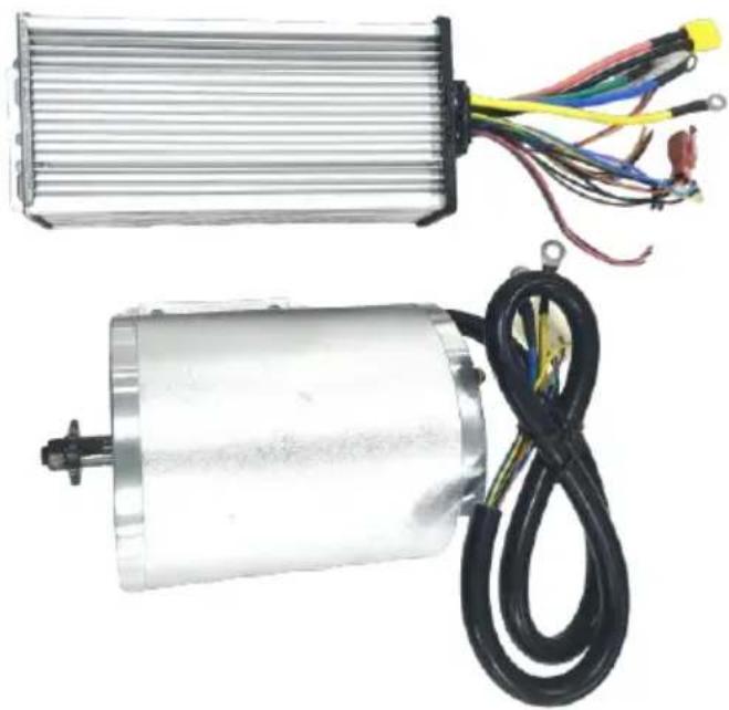
CONFIGURATION LIST
| ① Brushless DC motor (with foot X1 PCS | ② ZWK4835 Controller X1PCS |
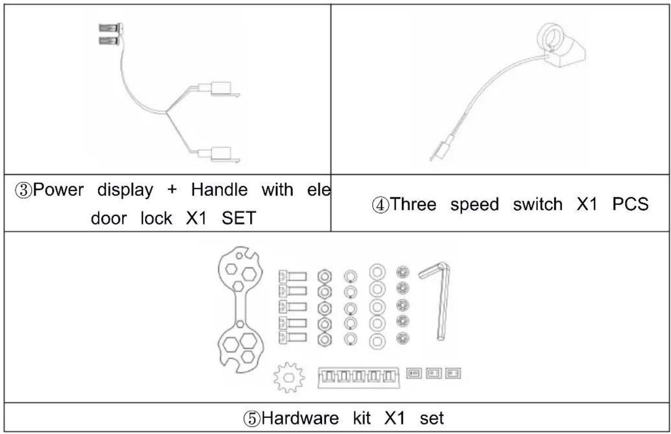
Table 1 Product configuration table
| Product number | Product configuration |
| ZLWSDJTJ200013XYAV9 | ①②⑤ |
| ZLWSDJTJ2000G4RXBV9 | ①②③⑤ |
| ZLWSDJTJ2000EEQF3V9 | ①②③④⑤ |
The specific accessories are subject to the purchased products. If the accessories are not in the list, you need to purchase them yourself.
Overall dimensions and mounting dimensions
The dimensions and mounting dimensions of the motor are shown in Figure
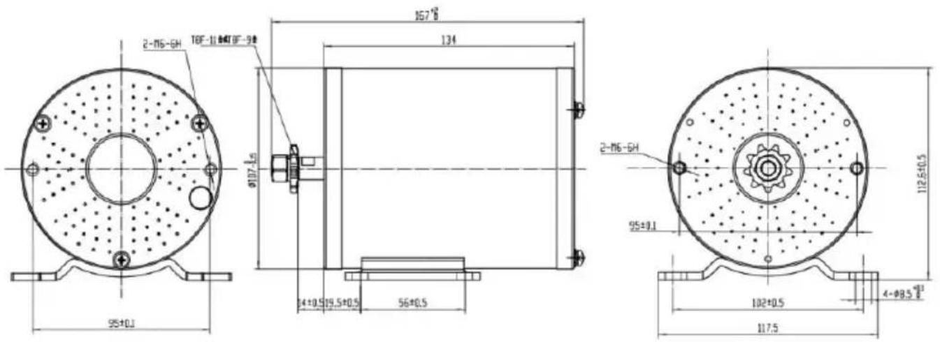
Figure 1 Motor dimensions and mounting dimensions
Install
1. Motor
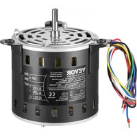
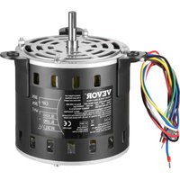
The A-phase line of the motor lead out main line is blue, the B-phase line and the C-phase line is yellow; The positive pole of the power supply in the line of the position sensor (Hall) is red, and the negative pole is black; The A-phase sensor signal line is blue, the B-phase sensor signal line is green, C-phase sensor signal line is yellow. The colors on both sides of the motor the same, and the motor wiring is shown in Figure 2.
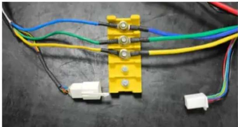
Figure 2 Motor wiring
2. Controller
There are one types of controllers. The functions of each plug-in are shown in Figure 3 below.
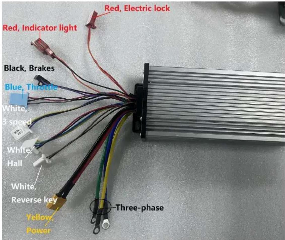
Figure 3 Controller
Controller voltage: DC48-54V
- Red 48V+
- Black 48V-
The positive and negative values cannot be connected incorrectly, otherwise the controller will burn out. There will be a slight spark when connected, which is normal start up phenomenon.
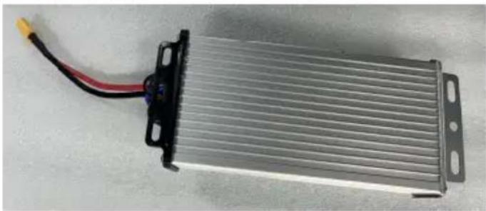
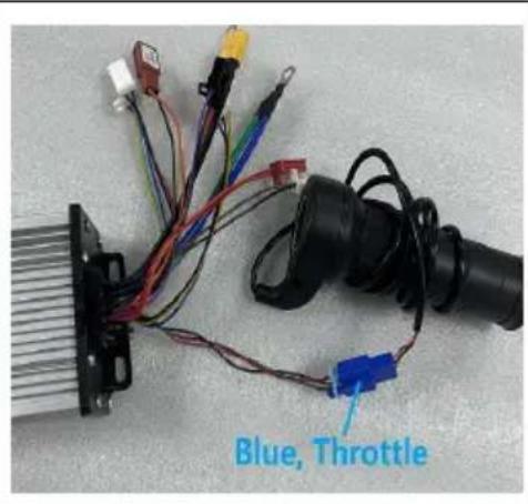
Figure 4 shows the controller cable connections.
3. Attachment
3.1Handle
Turn the handle line (turn the throttle).
- Red: +4.3V
- Black: Ground wire
- Gray: Signal line
The handle wiring is shown in Figure 5.
Handle function
Electric quantity displayelectric door lock hand

With three speed ^+ reverse forward handle
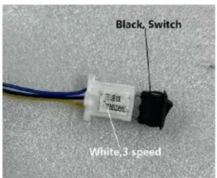
3.2Three-speed switch
Three speed switch: default speed 2, short circuit of blue and black lines is speed, short circuit of yellow and black lines is 1 speed.
There are several ways to connect the three speed switch, as shown in Fig.
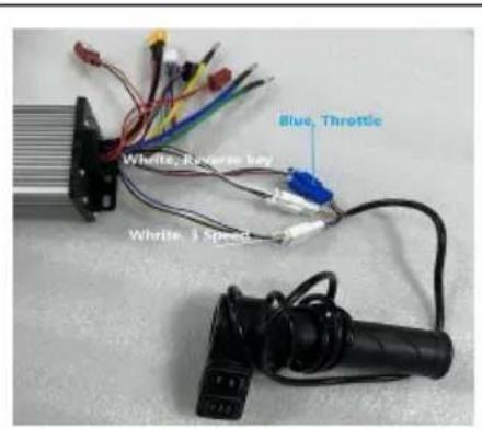
Fig.6 3 Speed wiring
1. Comes with 3 spee function
2. 3 foot switch control
3 speed
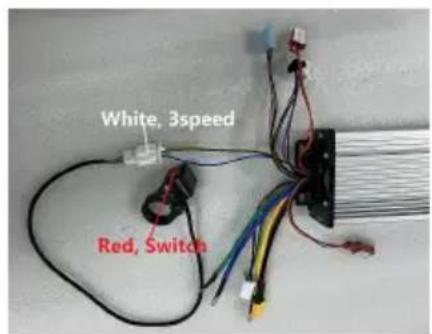
3. 3 speed switch controls
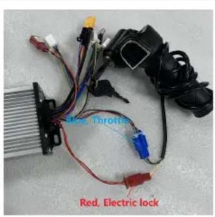
3.3 Electric door lock
Electric door lock: 1. Red: p+ 2. Orange: VCC
The electric door lock must be kept normally open, or the red and orange I
must be connected by a short circuit. Electric door lock wiring has the follow types, electric door lock wiring is shown in Figure 7.
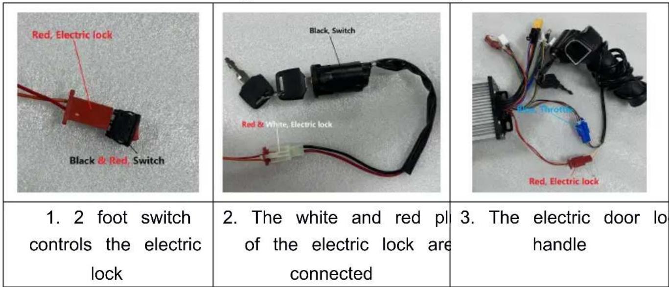
Fig.7 Electric lock wiring
4. Other accessories installation (purchase by oneself)
4.1 Reverse
Reverse: Switch brown and black, reverse speed is 100% . There are the following types of reverse cables. Figure 8 shows the reverse cables.
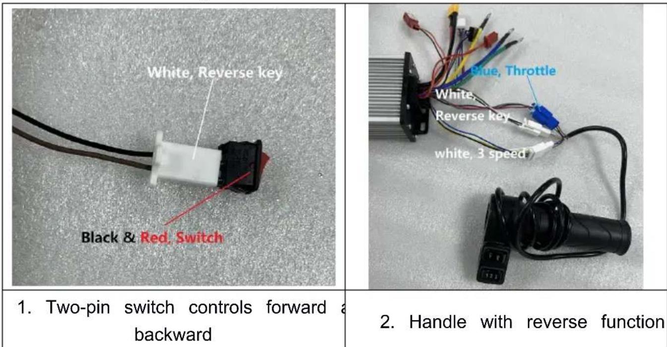
Figure 8 Reverse cable connection
4.2 Brake
Brake: Connect the brake to realize the brake power off function. Brake wirin shown in Figure 9.
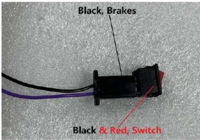
Figure 9 Brake wiring
4.3 Indicator lights
Indicator light: Connected to the battery level display, it can be used as a DC voltage output for DC48V to emit light. The positive and negative terminals c be reversed. Orange is 48V+ and black is 48V- . The wiring of the indicator shown in Figure 10.
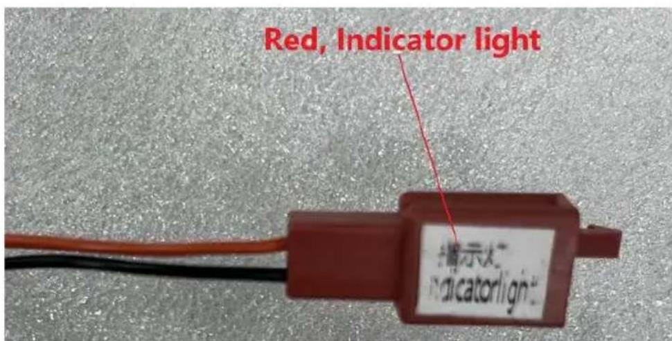
Figure 10 Wiring of indicator lights
4.4 Pedal/accelerator
Pedal/accelerator wire (twist throttle).
- Red: +4.3V
- Black: Ground wire
- Gray: Signal line
The pedal/accelerator wiring is shown in Figure 11.
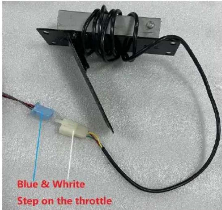
Fig.11 Step on the throttle wiring
COMMON PROBLEMS AND REMEDIES
Phenomenon:
The electronic lock must be opened, When the electronic lock is opened, the throttle is turned and the motor does not work
Reason:
Battery The battery is too low and does not reach the required operating vo
Solution:
- Charging ;
- Select a battery with the corresponding operating voltage;
- Check whether each plug-in is connected correctly and whether the connect terminals are connected reliably, so as to avoid failure to work normally due incorrect connection or poor contact.
CORRECT DISPOSAL

This product is subject to the provision of european Directive
2012/19/EU. The symbol showing a wheelie bin crossed through
indicates that the product requires separate refuse collection in the
European Union. This applies to the product and all accessories marked with symbol. Products marked as such may not be discarded with normal domestic waste, but must be taken to a collection point for recycling electrical and electronic devices.
FCC Information:
CAUTION: Changes or modifications not expressly approved by the party responsible for compliance could void the user's authority to operate the equipment!
This device complies with Part 15 of the FCC Rules. Operation is subject to following two conditions:
1) This product may cause harmful interference.
2) This product must accept any interference received, including interference that may cause undesired operation.
WARNING: Changes or modifications to this product not expressly approved by the party.responsible for compliance could void the user's authority to operate product.
Note: This product has been tested and found to comply with the limits for B digital device pursuant to Part 15 of the FCC Rules, These limits are desto provide reasonable protection against harmful interference in a residential installation.
This product generates, uses and can radiate radio frequency energy, and if installed and used in accordance with the instructions, may cause harmful interference to radio communications. However, there is no guarantee that interference will not occur in a particular installation. If this product does cause
harmful interference to radio or television reception, which can be determined by turning the product off and on, the user is encouraged to try to correct the interference by one or more of the following measures.
- Reorient or relocate the receiving antenna.
- Increase the distance between the product and receiver.
- Connect the product to an outlet on a circuit different from that to which receiver is connected.
- Consult the dealer or an experienced radio/TV technician for assistance.
Manufacturer: Shanghaiuxinmuyeyouxianggsi
Address: Shuangchenglu 803nong11hao1602A-1609shi, baoshanqu, shanghai 200000 CN.
Imported to AUS: SIHAO PTY LTD. 1 ROKEVA STREETEASTWOOD NSW 2122 Australia
Imported to USA: Sanven Technology Ltd. Suite 250, 9166 Anaheim Place, Rancho Cucamonga, CA 91730

YH CONSULTING LIMITED.
C/O YH Consulting Limited Office 147, Centurion House, London Road, Staines-upon-Thames, Surrey, TW18 4A
Technical Support and E-Warranty Certificate
www.vevor.com/support
VEVOR®
TOUGH TOOLS, HALF PRICE
Assistance technique et certificat de garantie electronique www.vevor.com/support
A/S YH Consulting Limited Bureau 147,
Centurion House, London Road,
Staines-upon-Thames, Surrey, TW18 4AX

E-CrossStu GmbH
Mainzer Landstr.69, 60329 Francfort-sur-le-Main
Principal.
VEVOR
TOUGH TOOLS, HALF PRICE
4.4 Pedal/Gaspedal Pedal/
C/O YH Consulting Limited Office 147, Centurion House, London Road, Staines-upon-Thames, Surrey, TW18 4A
www.vevor.com/support
VEVOR®
TOUGH TOOLS, HALF PRICE
Machine Translated by Google
yKit hardware X1 set
Importato in AUS: SIHAO PTY LTD. 1 ROKEVA STREETEASTWOOD NSW 2122 Australia
Importato negli USA: Sanven Technology Ltd. Suite 250, 9166 Anaheim Place, Rancho Cucamonga, CA 91730

CONSULENZA YH LIMITATA.
C/O YH Consulting Limited Ufficio 147,
Centurion House, London Road,
Staines-upon-Thames, Surrey, TW18 4AX
E-CrossStu GmbH
Mainzer Landstr.69, 60329 Francoforte am
Principale.
VEVOR
TOUGH TOOLS, HALF PRICE
elettronica www.vevor.com/support
VEVOR®
TOUGH TOOLS, HALF PRICE
Soporte专业技术o y certificate de garantia electrònica www.vevor.com/support
Motor de corriente continua sin escobillas
Modelo: JZ48V2000W
Centurion House, London Road,
Staines-upon-Thames, Surrey, TW18 4AX

E-CrossStu GmbH
Mainzer Landstr.69, 60329 Francfort del Meno
Principal.
VEVOR
TOUGH TOOLS, HALF PRICE
Soporte专业技术o y certificate de garantia
electrónica www.vevor.com/support
VEVOR®
TOUGH TOOLS, HALF PRICE
C/O YH Consulting Limited Biuro 147, Centurion House, London Road, Staines-upon-Thames, Surrey, TW18 4A

E-CrossStu GmbH
Mainzer Landstr.69, 60329 Frankfurt am Gówny.
VEVOR
TOUGH TOOLS, HALF PRICE
HULP NODIG? NEEM CONTACT MET ONS OP!
C/O YH Consulting Limited Kantoor 147, Centurion House, London Road, Staines-upon-Thames, Surrey, TW18 4AX
E-CrossStu GmbH
Mainzer Landstr.69, 60329 Frankfurt am Voornaamst.
VEVOR
TOUGH TOOLS, HALF PRICE
garantiecertificaat www.vevor.com/support
VEVOR®
TOUGH TOOLS, HALF PRICE
C/O YH Consulting Limited Office 147, Centurion House, London Road, Staines-upon-Thames, Surrey, TW18 4AX

www.vevor.com/support