BTC002C - Garden trailer Vevor - Free user manual and instructions
Find the device manual for free BTC002C Vevor in PDF.

| Brand | Vevor |
| Model | BTC002C |
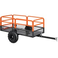
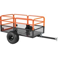
| Product Type | Garden Trailer |
| Volume | 12 to 15 ft³ (0.34 to 0.42 m³) |
| Dimensions (L x W x H) | 1170 x 760 x 500 mm |
| Maximum Load Capacity | 340 kg (750 lb) |
| Main Material | Steel |
| Number of Wheels | 2 |
| Wheel Type | Pneumatic |
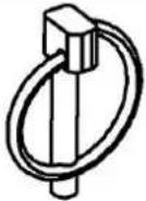
| Hitch System | Tow bar with bolt and R-pin |
| Intended Use | Transport of garden materials, tools, etc. |
| Assembly Required | Yes, by 2 people in about 20 minutes |
| Spare Parts Available | Yes, via manufacturer |
| Maintenance | Clean with water, inspect before each use |
| Storage | In a dry and clean place |
| Safety Precautions | Do not sit or stand on the trailer |
| Do not exceed maximum load | Risk of injury and damage |
| Inspection before use | Check that all parts are tight and not damaged |
| Use on flat surface | Recommended for stability |
| Warranty | Refer to the manual or Vevor website |
Frequently Asked Questions - BTC002C Vevor
User questions about BTC002C Vevor
0 question about this device. Answer the ones you know or ask your own.
Ask a new question about this device
Download the instructions for your Garden trailer in PDF format for free! Find your manual BTC002C - Vevor and take your electronic device back in hand. On this page are published all the documents necessary for the use of your device. BTC002C by Vevor.
USER MANUAL BTC002C Vevor
Affordable. Reliable. Home Improvement.
GARDEN TRAILER
MODEL: BTC002C
MODEL: BTC002C
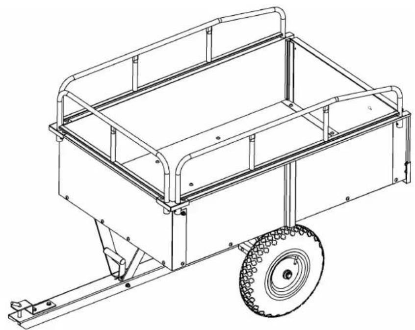
natural_image
Technical line drawing of a wheeled cart with a wheel, showing frame structure and mounting brackets (no text or symbols)
https://youtu.be/kmog4Ez0O8k
For the installation video, please scan the QR code to access.
This is the original instruction, please read all manual instructions carefully before operating. VEVOR reserves a clear interpretation of our user manual. The appeal of the product shall be subject to the product you received. Please forgive us won't inform you again if there are any technology or software updates on our
WARNING:
Read this material before using this product. Failure to do so can result in seri injury.
Assembly precautions
- Assemble only according to these instructions. Improper assembly can create hazard
- Wear ANSI-approved safety goggles and heavy-duty work gloves during assembly.
- Keep the assembly area clean and well-lit.
- Keep bystanders out of the area during assembly.
- Do not assemble if tired or when under the influence of alcohol, drugs or medical
- The product capabilities apply to properly and completely assembled products only.
- Assemble on a flat, level, hard and smooth surface capable of safely supporting the Garden Trailer.
- For additional information regarding the parts listed in the following pages, please run the Assembly Diagram of this manual. Unwrap and separate all parts in a clean
- It is estimated that the installation of this product can be completed in 20 minutes person.
- Since a large number of screws are required for assembling this product, we have provided spare screws. Therefore, there is no need to worry if you have any rem screws after completing the product assembly.
Use precautions
- DO NOT SIT OR STAND ON THIS ITEM.
- This product is not a toy. Do not allow children to play with or near this item.
- Do not exceed specified weight capacities.
- Use only on a flat, level, hard, and smooth surface that can safely support a fully Garden Trailer.
- Use as intended only.
- Inspect before every use; do not use if parts are loose or damaged.
SAVE THIS MANUAL
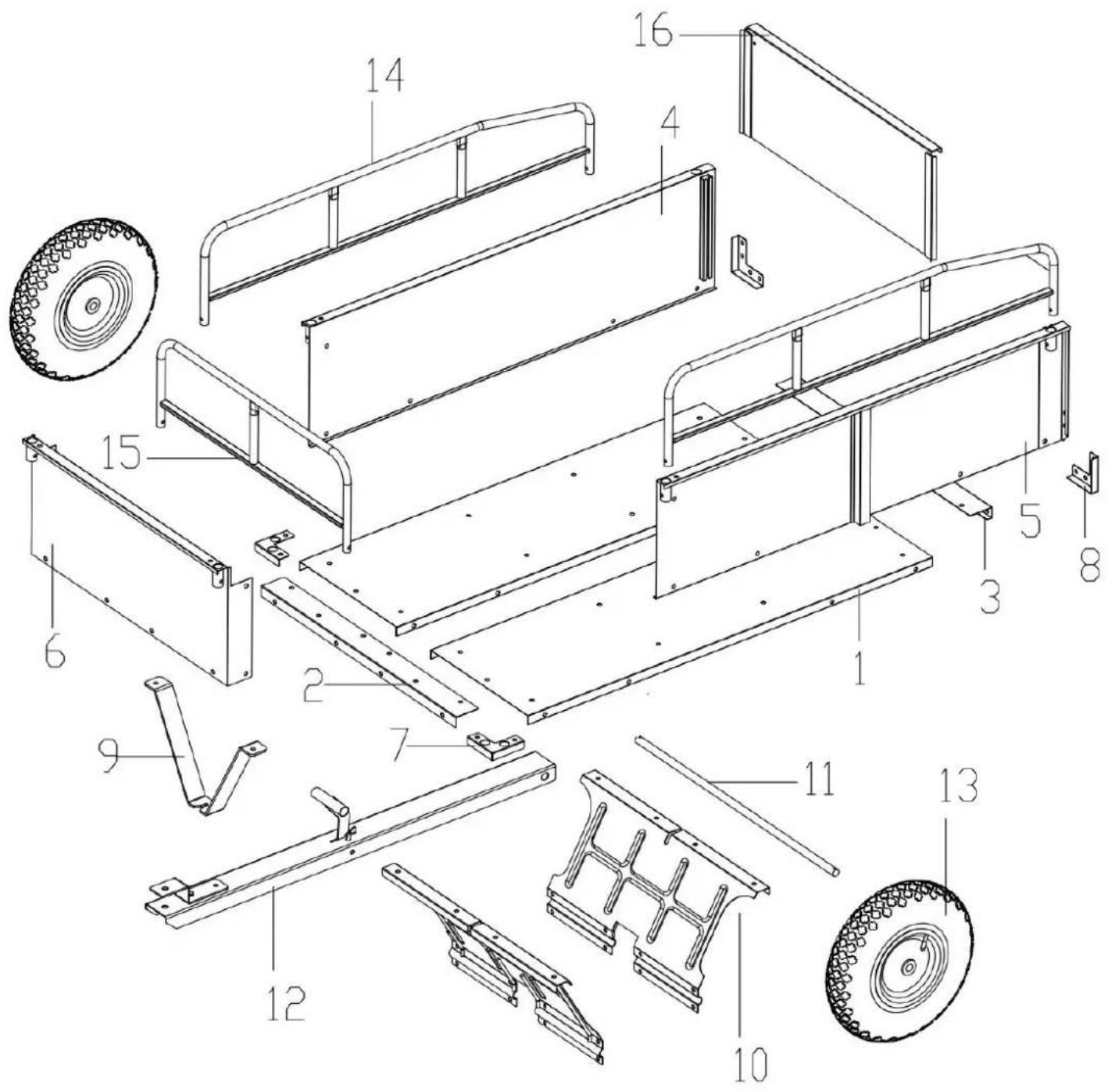
PARTS LIST
| No. | Part | QTY. | No. | Part | QTY. |
| 1 | 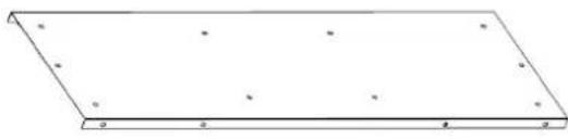 | 2 | 2 | 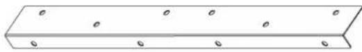 | 1 |
| 3 | 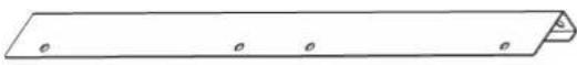 | 1 | 4 |  | 1 |
| 5 |  | 1 | 6 | 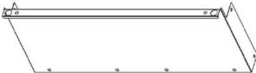 | 1 |
| 7 | 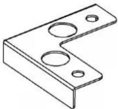 | 2 | 8 | 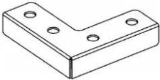 | 2 |
| 9 | 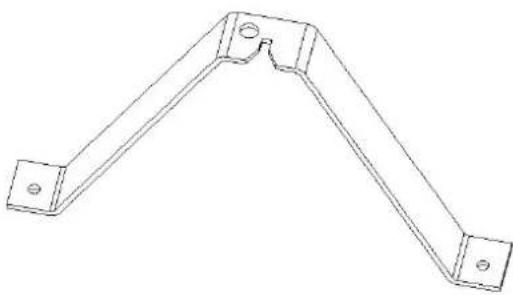 | 1 | 10 | 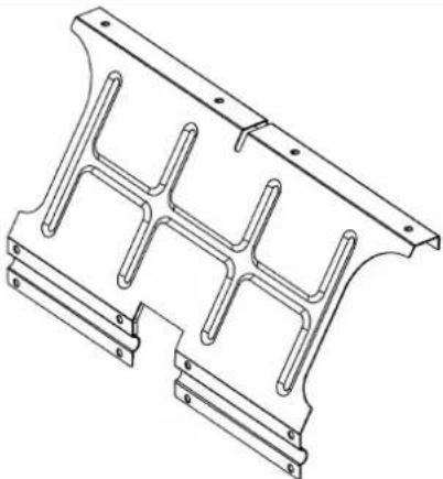 | 2 |
| 11 |  | 1 | 12 | 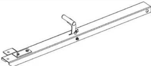 | 1 |
| 13 | 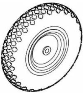 | 2 | 14 |  | 2 |
| 15 | 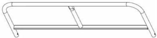 | 1 | 16 | 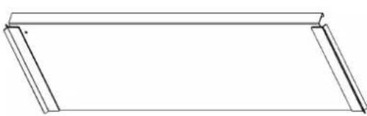 | 1 |
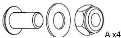
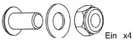
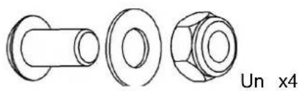
| A | 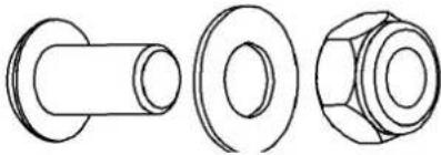 M8*15mm M8*15mm | 54 | B |  M8*30mm M8*30mm | 2 |
| C |  | 4 | D | 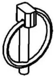 | 2 |
| E | 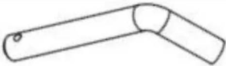 | 1 | F |  | 2 |
 | 1 |  | 1 | ||
ASSEMBLY STEP
| Step 2 | |
 Ax8 Ax8 |  |
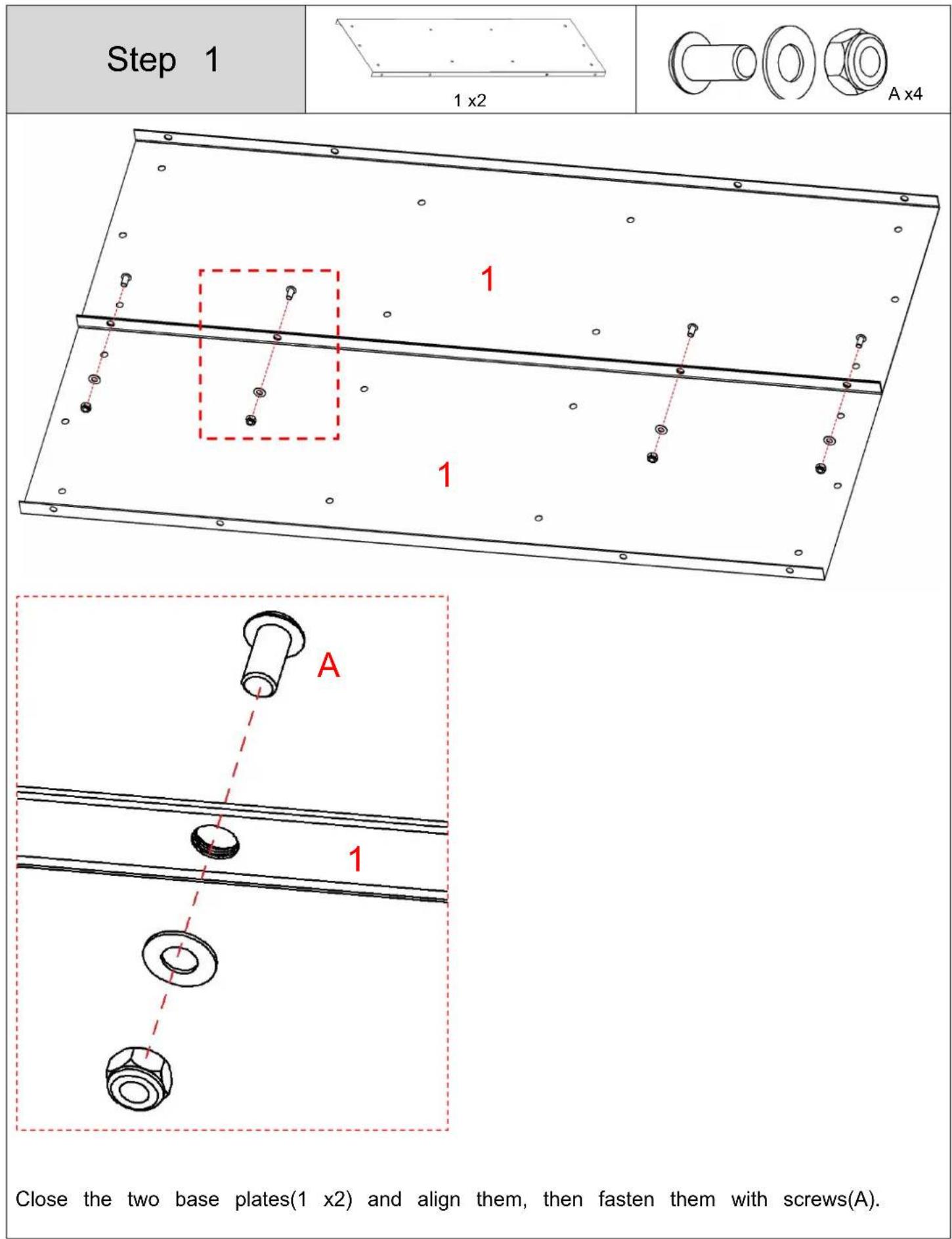
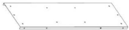
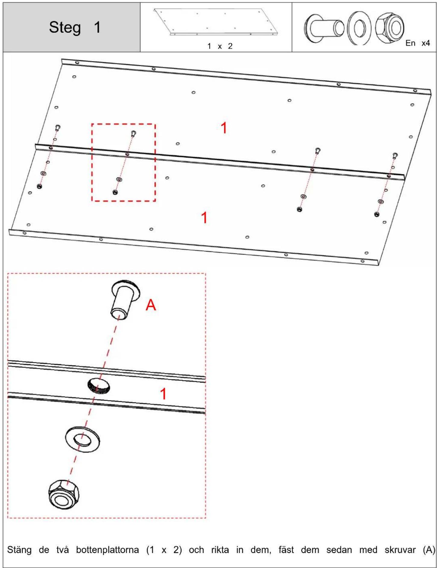
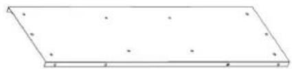
- Flip the base plate(1) to the other side and then install it.
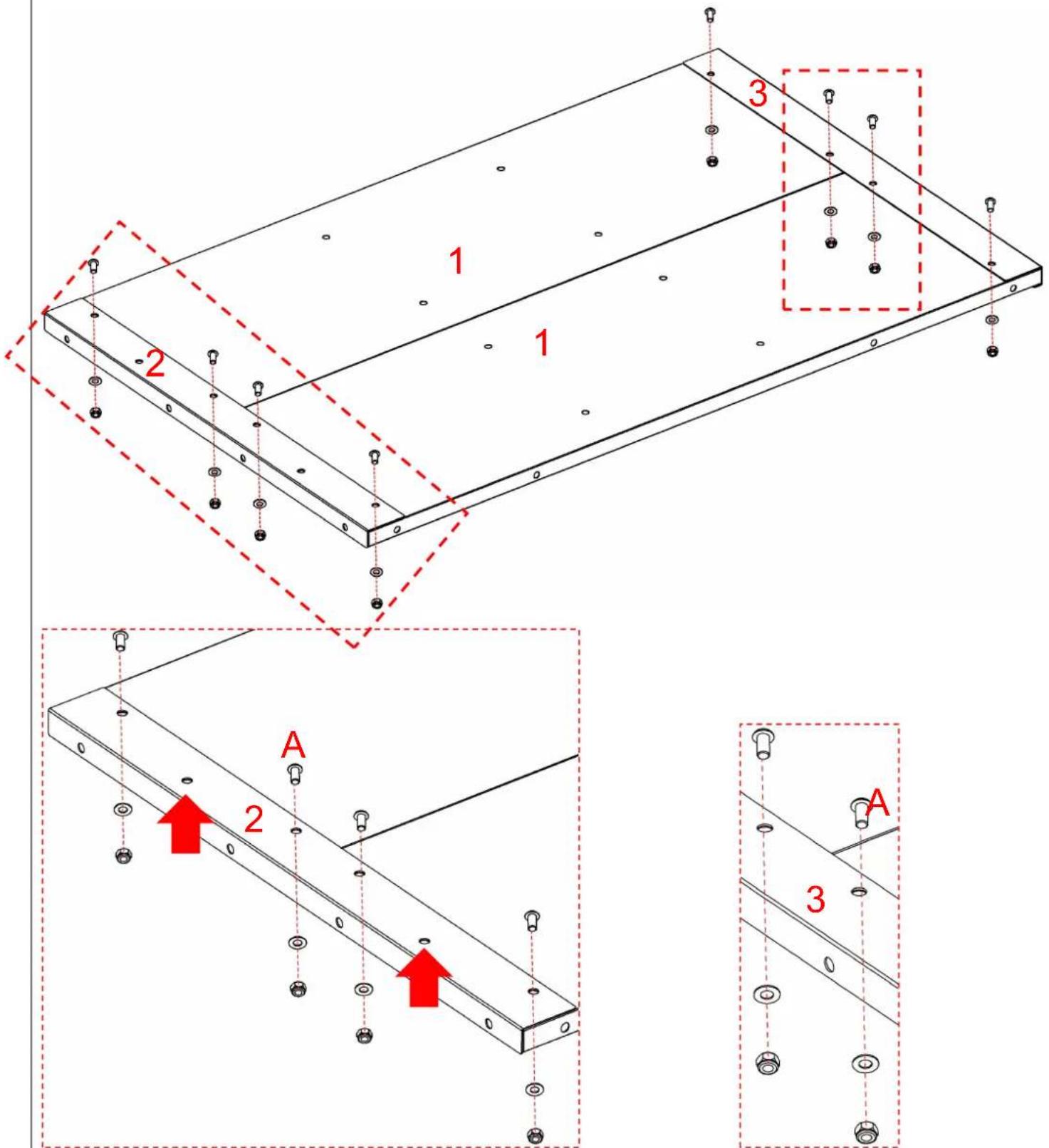
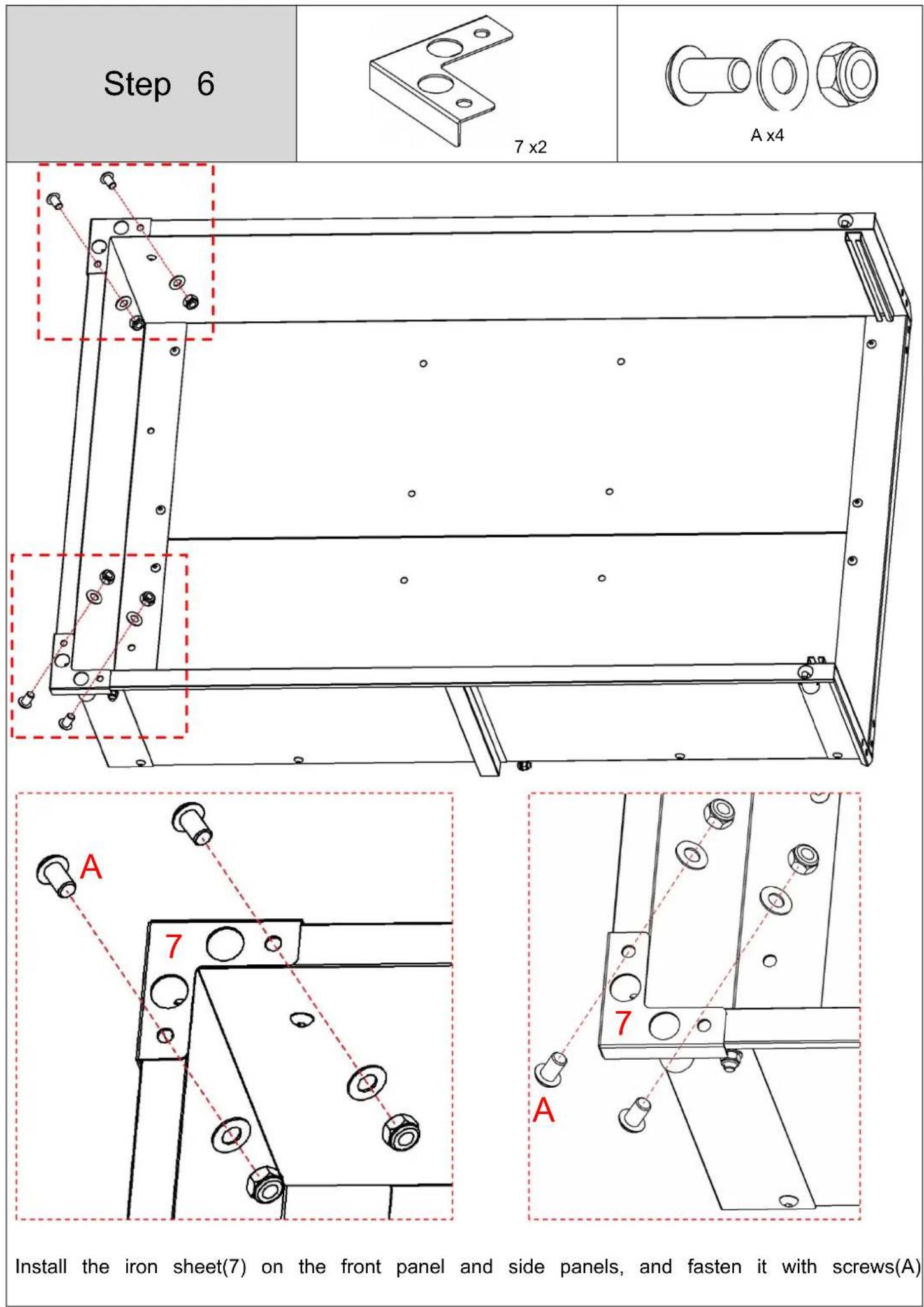
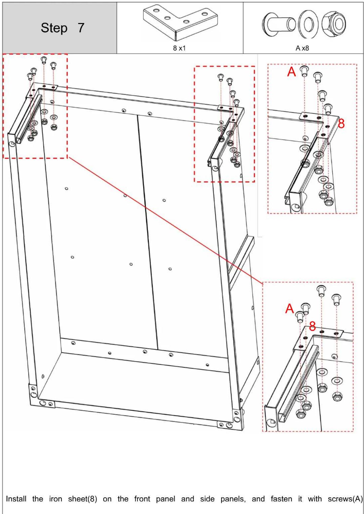
- Install angle iron(2;3) at both ends respectively, and fasten them with screws(A).
Caution: Do not screw the two mounting holes marked by the arrow on angle iron time being; they are reserved for use in subsequent installation steps.
| Step 3 | 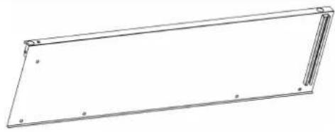 4 x1 4 x1 | 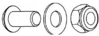 A x3 A x3 |

Align the side panel(4) with the base plate(1) and secure them with screws(A). Caution: Do not install screws in the 1 marked hole (indicated by the arrow on th This hole is reserved for a subsequent assembly step.
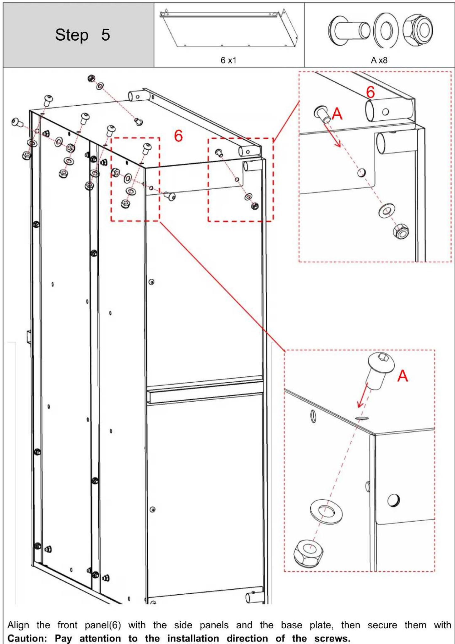
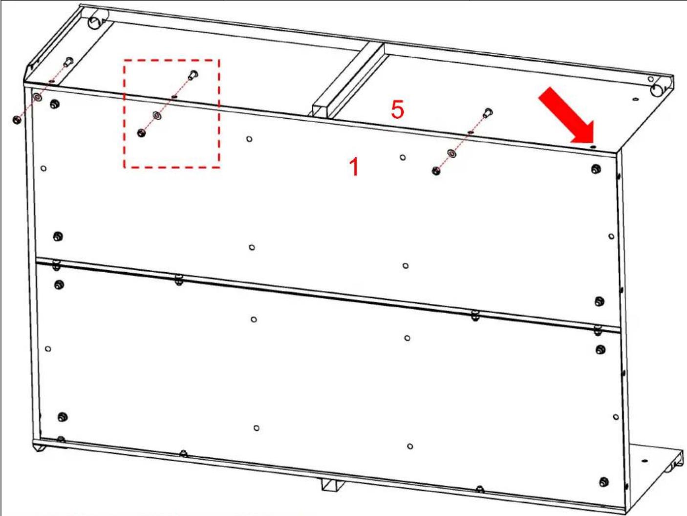
| Step 4 | 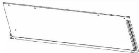 5 x1 5 x1 | 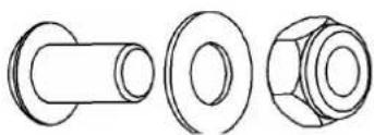 A x3 A x3 |
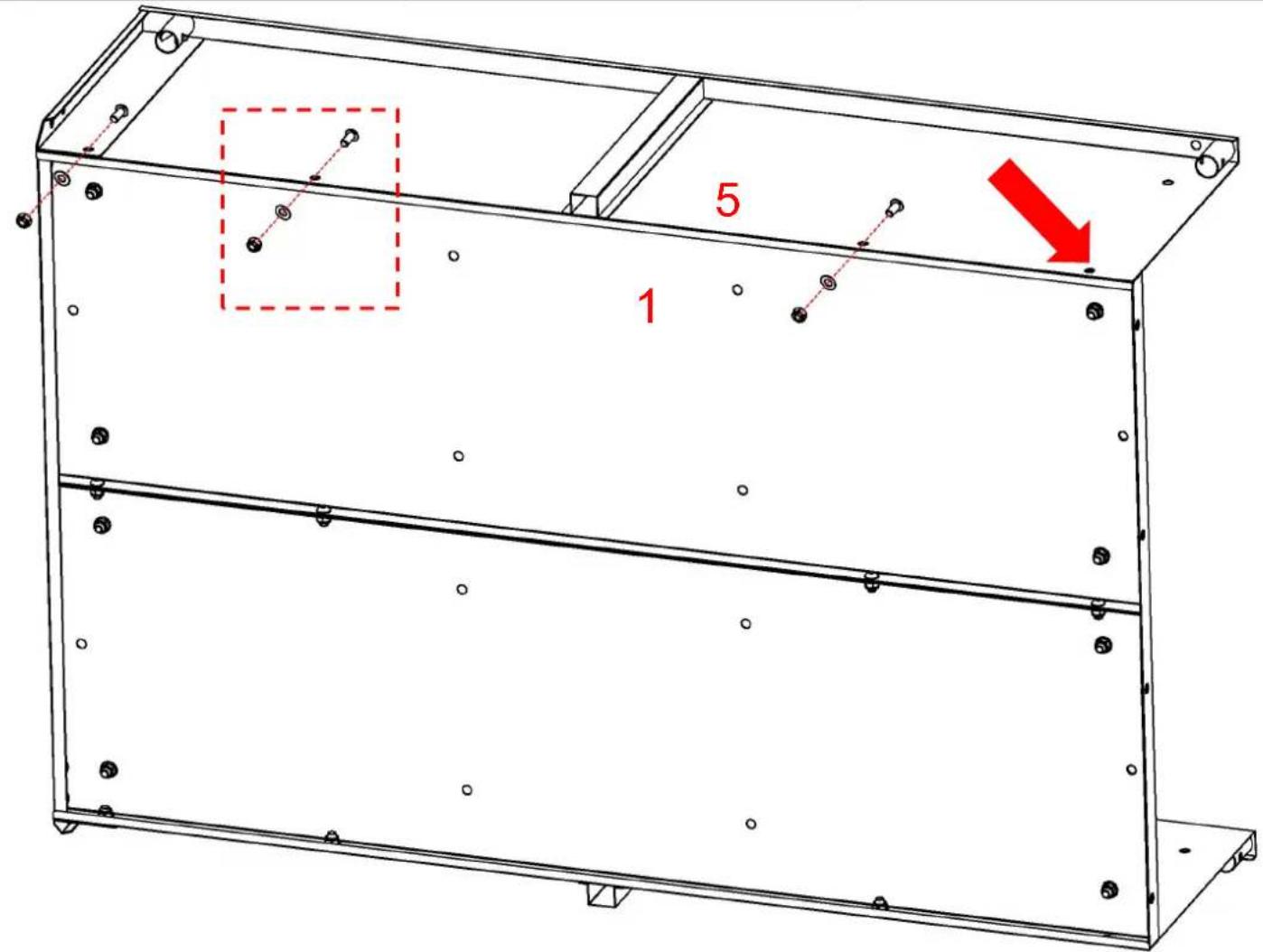
Align the side panel(5) with the base plate(1) and secure them with screws(A). Caution: Do not install screws in the 1 marked hole (indicated by the arrow on th This hole is reserved for a subsequent assembly step.
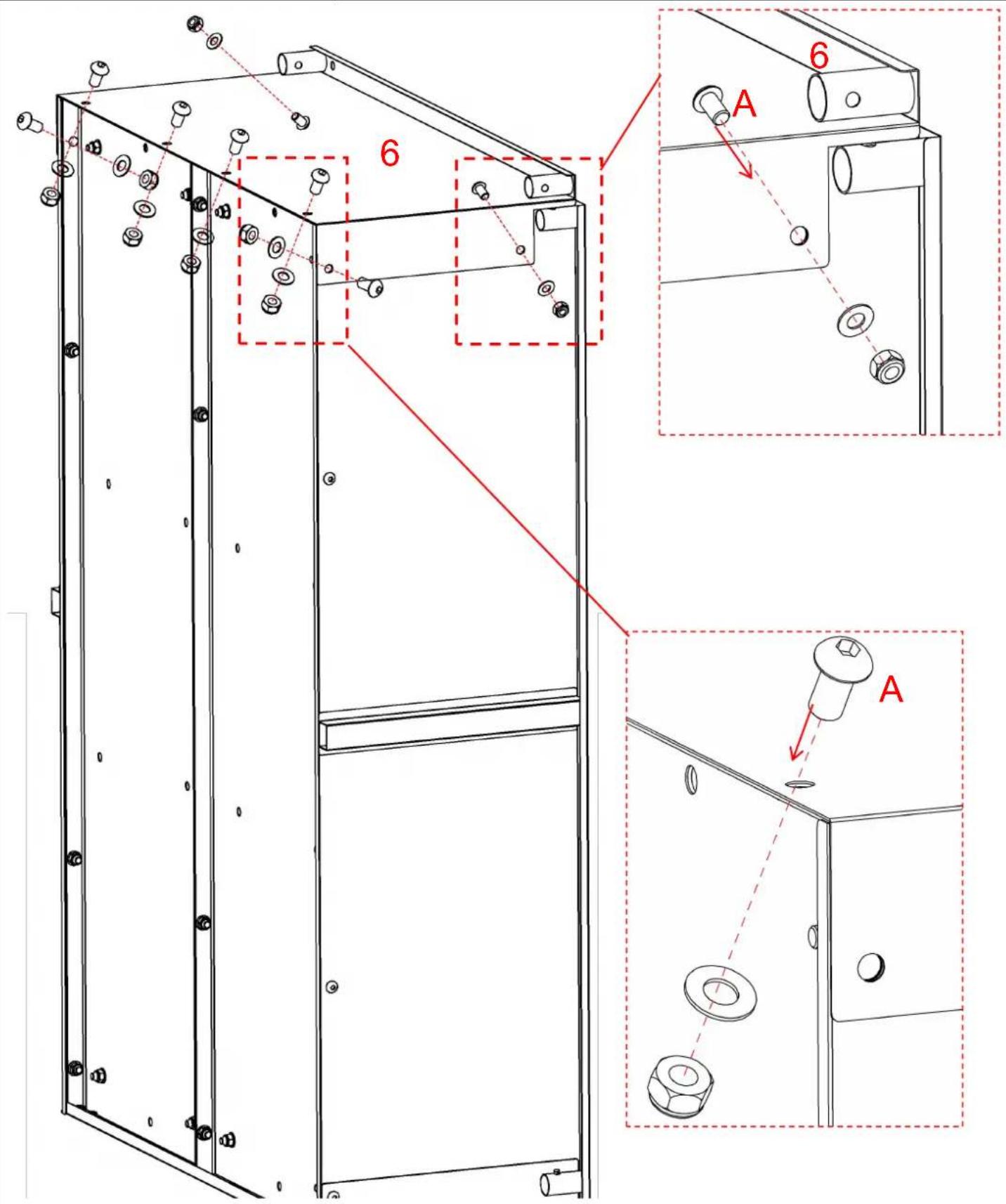
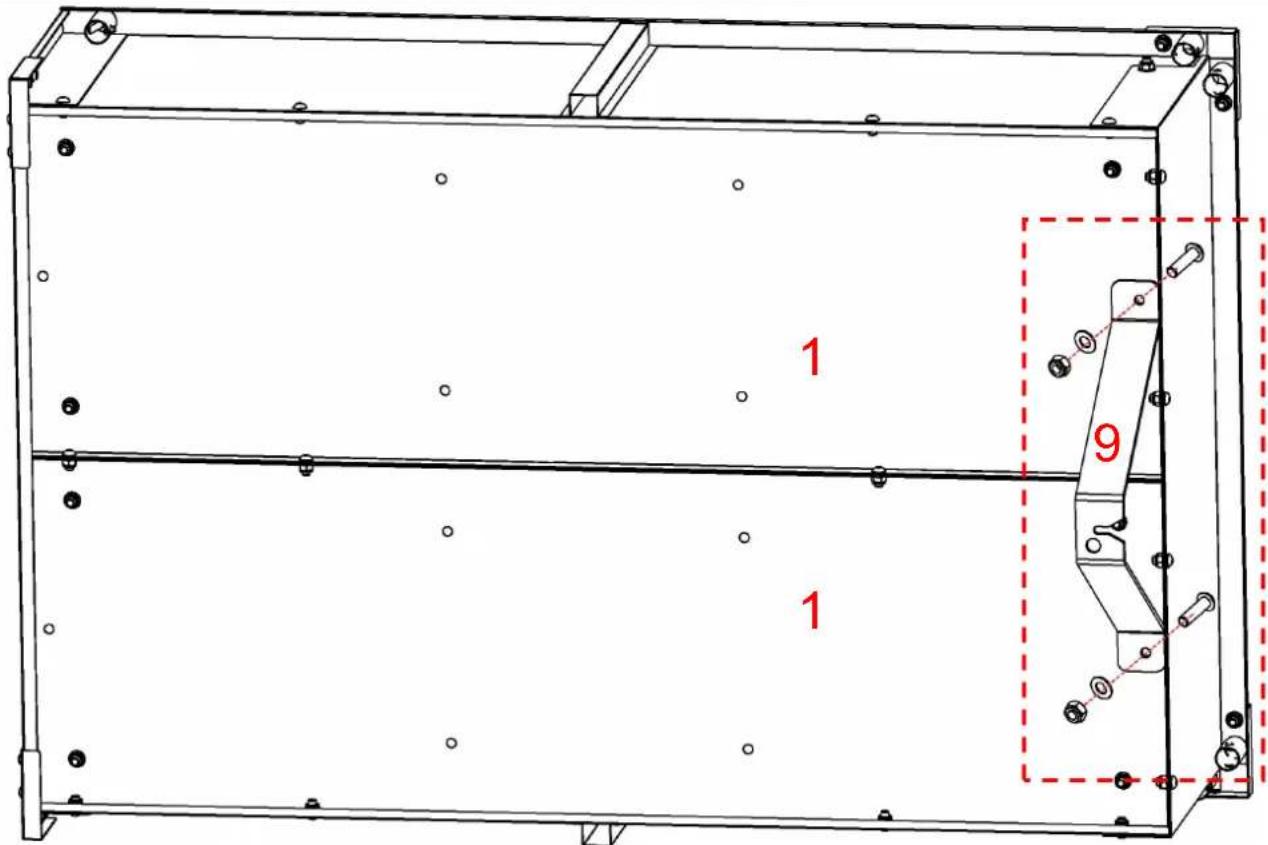
Step 8
natural_image
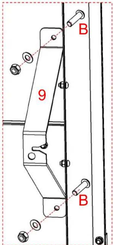
Technical line drawing of a V-shaped metal bracket with two mounting holes (no text or symbols)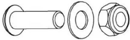
natural_image
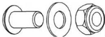
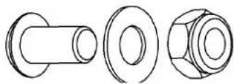
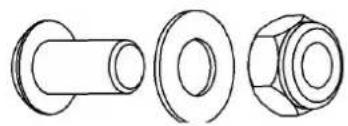
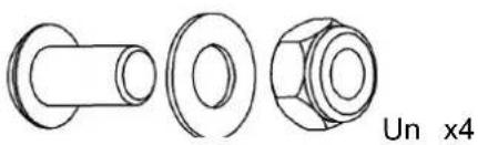
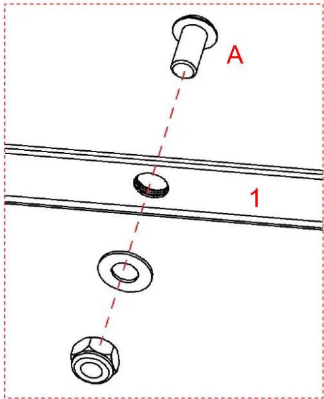
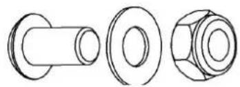
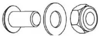
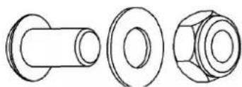
Technical line drawings of three mechanical components: a cylindrical shaft, a flanged bolt, and a hexagonal nut (no text or symbols)B x2

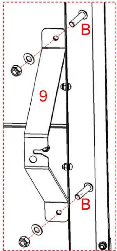
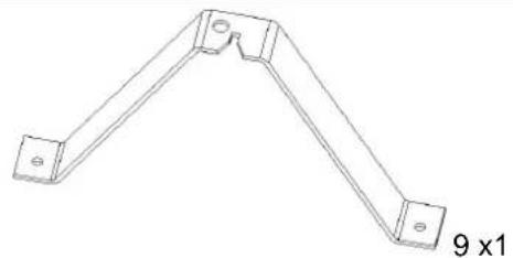
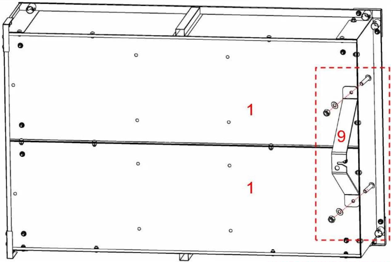
Install the V-shaped bracket(9) onto the base plate and fasten it with the corresponding (these screws are relatively long).
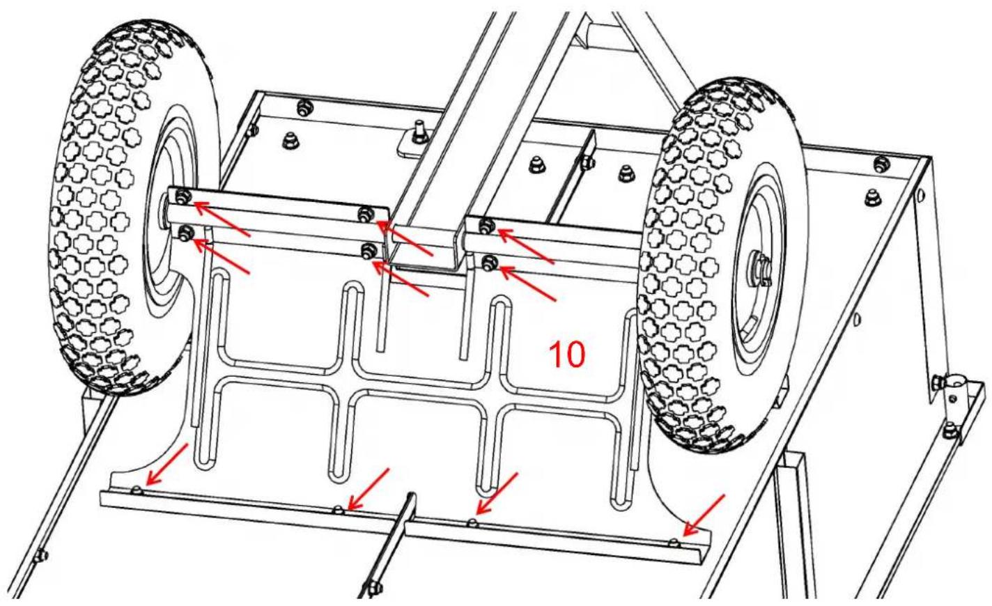
| Step 9 | 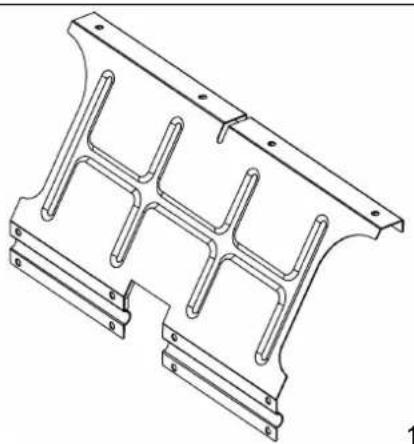 0 x2 0 x2 | 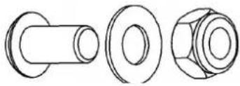 Ax8 Ax8 |
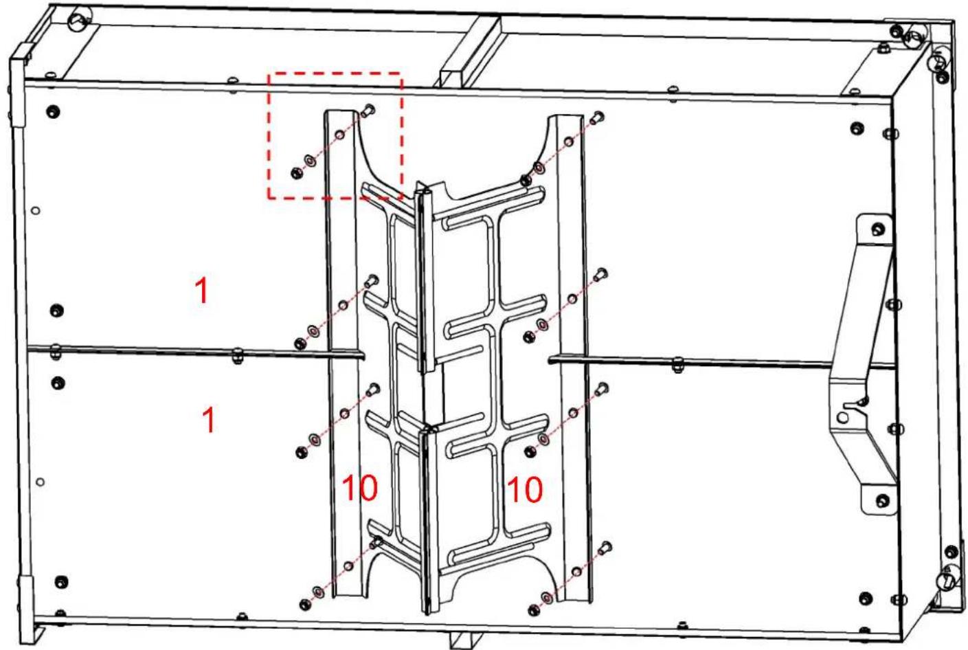
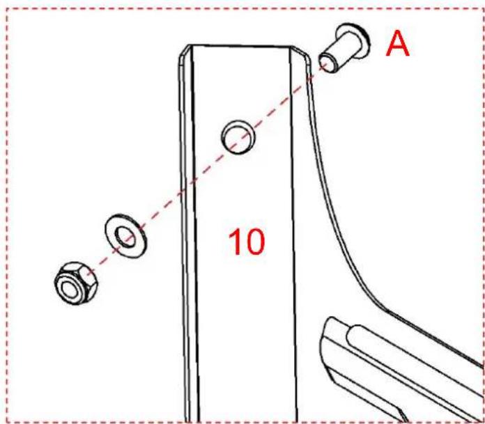
Place the iron plate(10) in the direction s in the diagram, align it at the middle pos and then fix it to the base plate with sc
Caution: Do not tighten the screws her the time being; they are reserved to be tightened in subsequent steps.
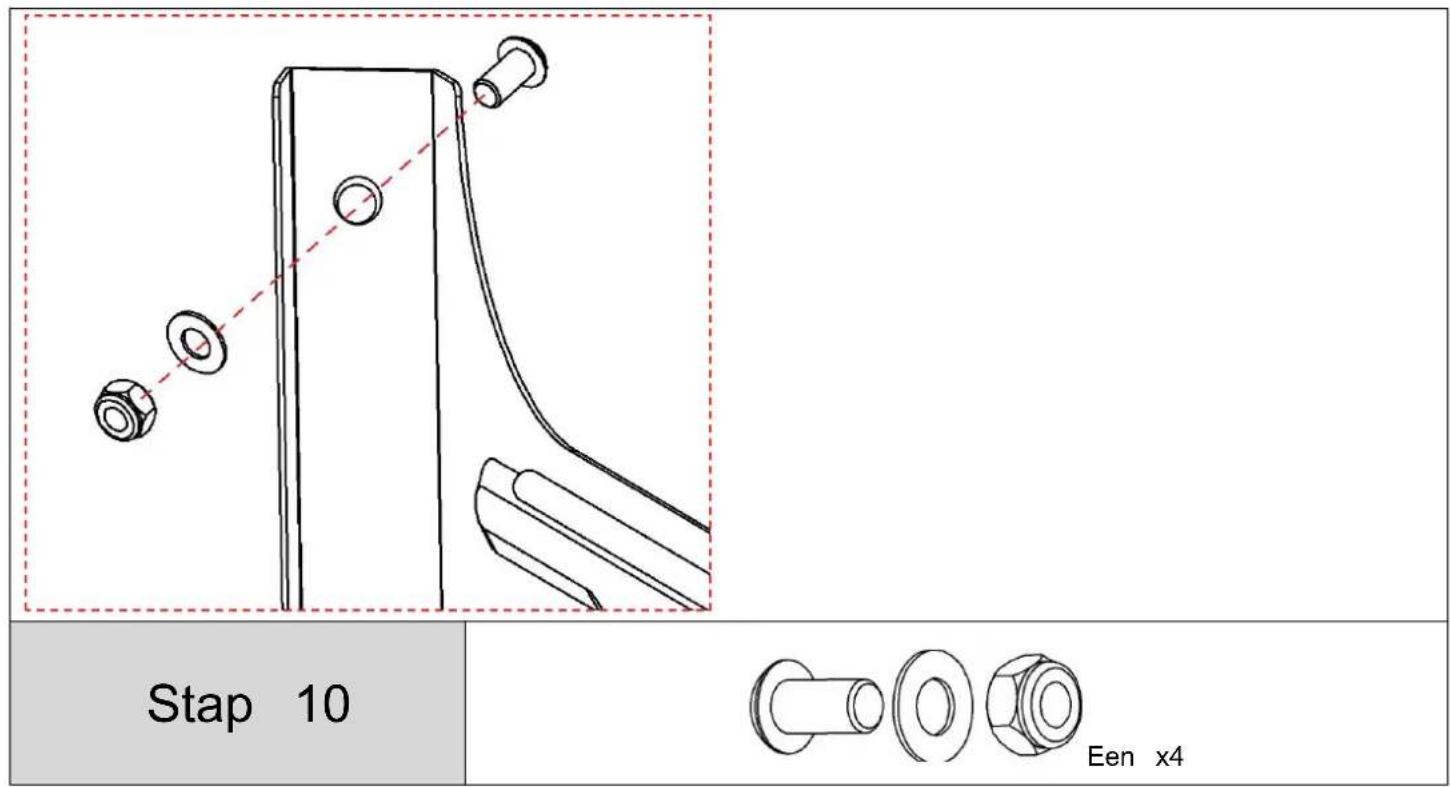
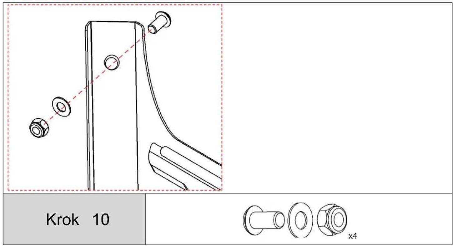
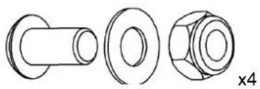
Step 10

natural_image
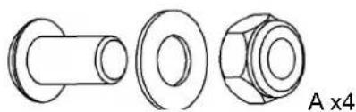
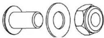
Technical line drawings of three mechanical components: a cylindrical bolt, a flanged nut, and a hexagonal bolt (no text or symbols)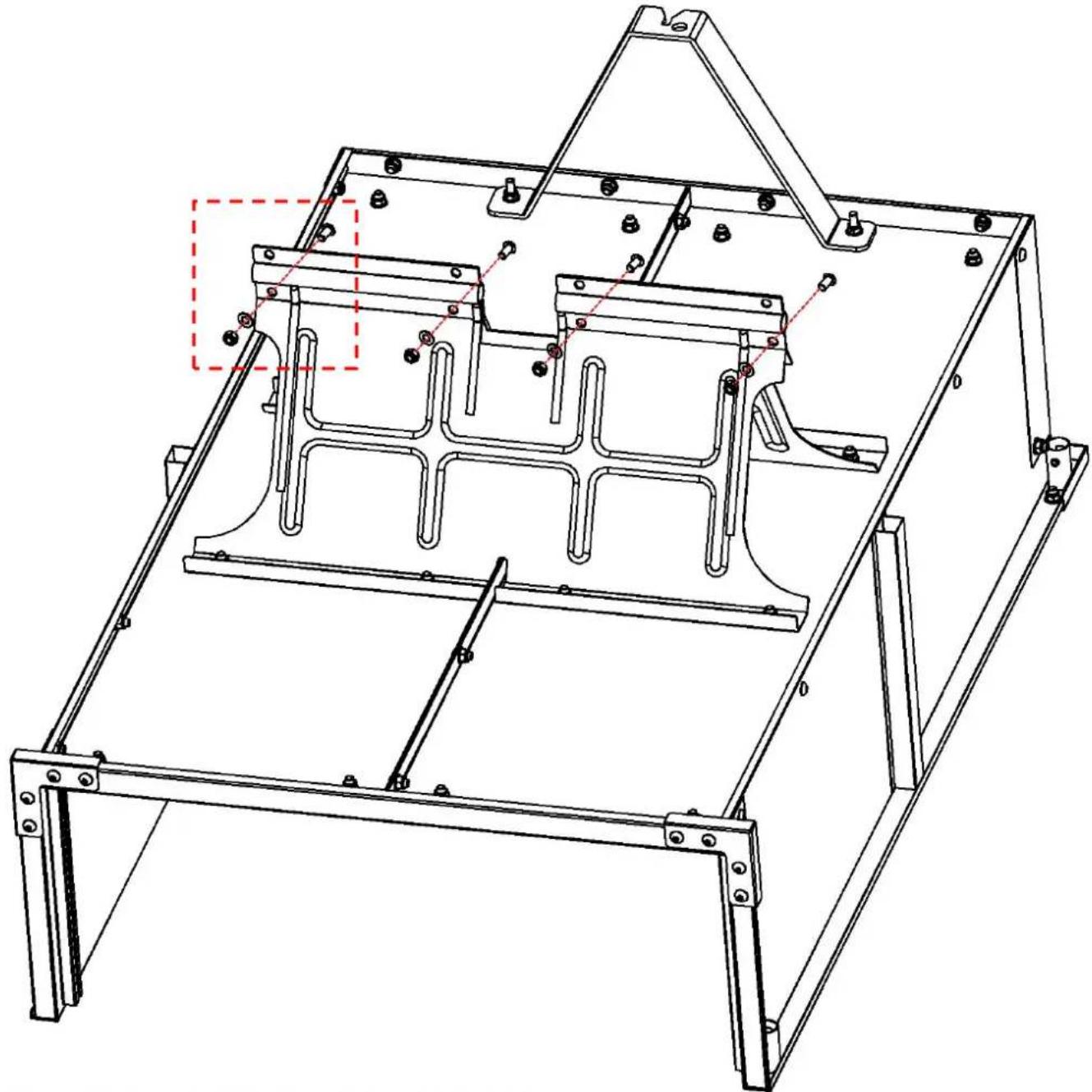
natural_image
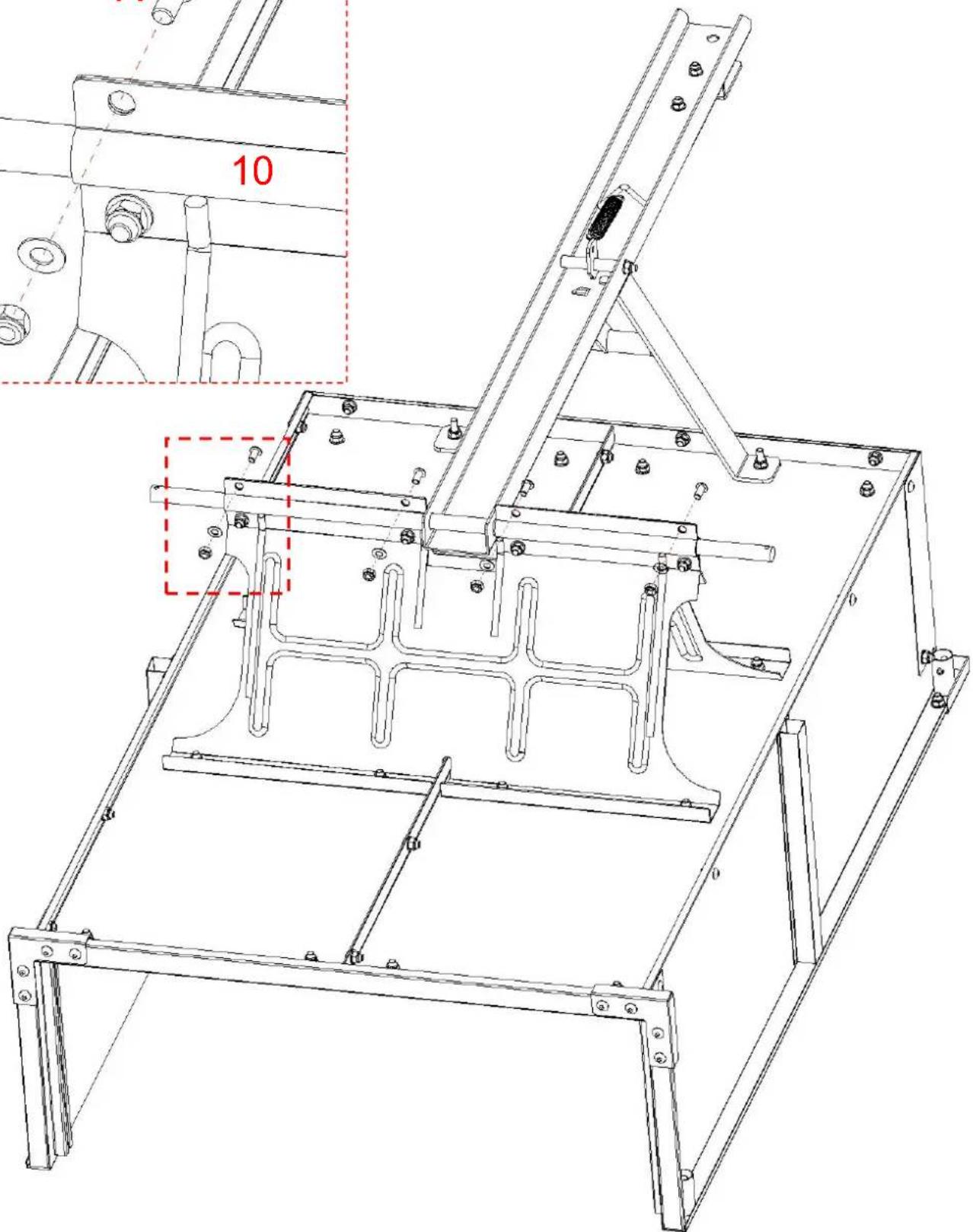
Technical line drawing of a mechanical frame assembly with mounting brackets and structural supports (no text or symbols)
-
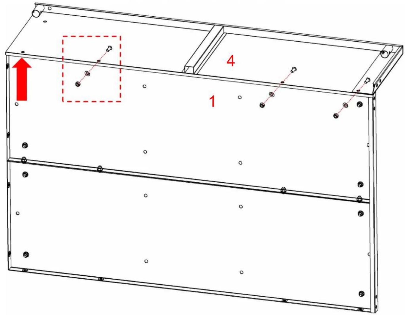
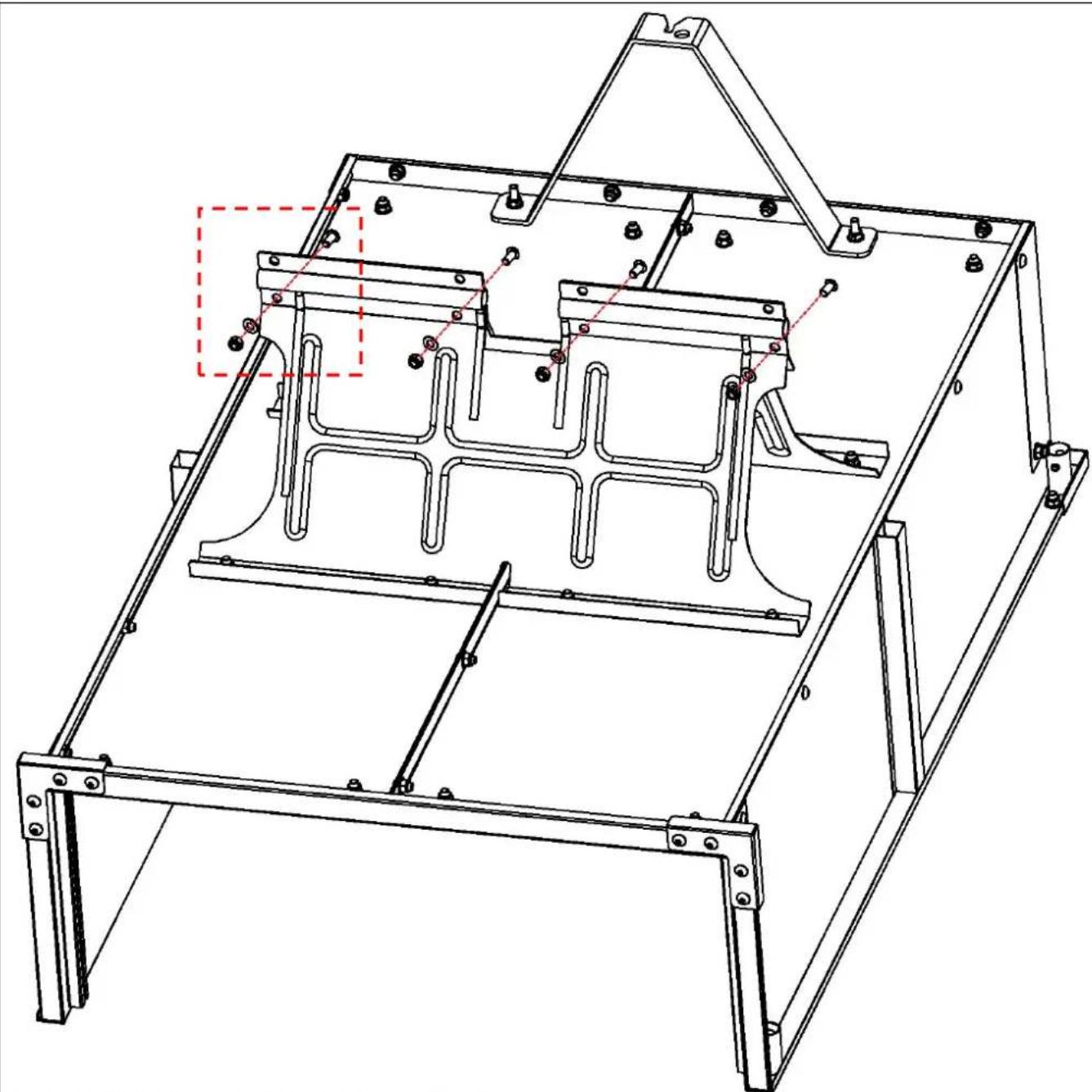
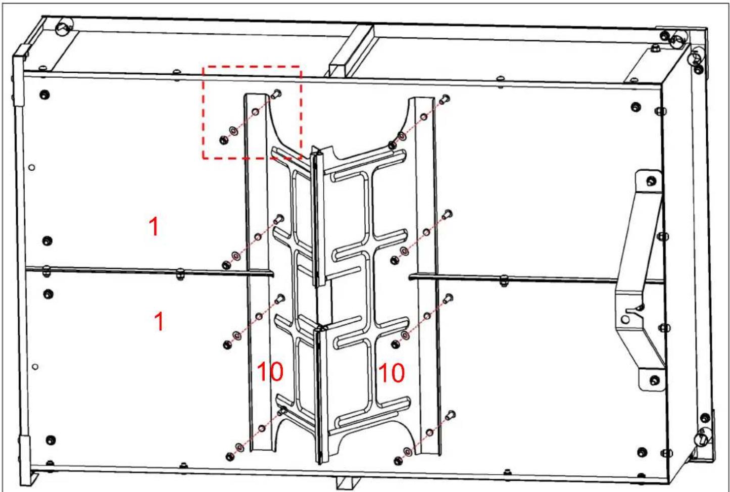
Securely connect the two iron plates(10) v screws(A).
-
Caution: There are a total of 8 screw h here. At this stage, only the 4 lower ones to be tightened, and the remaining holes reserved for tightening in subsequent steps
-
Caution: Do not tighten the screws here, the time being; they are reserved to be tightened in subsequent steps.
Step 11
natural_image
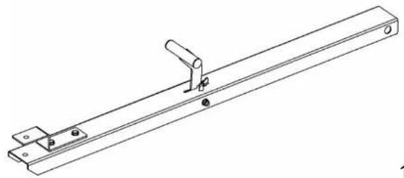
Technical line drawing of a mechanical lever assembly (no text or symbols)12 x1

natural_image
Simple line drawing of a cylindrical object with a circular end marked '11 x1' (no text or symbols on the object itself)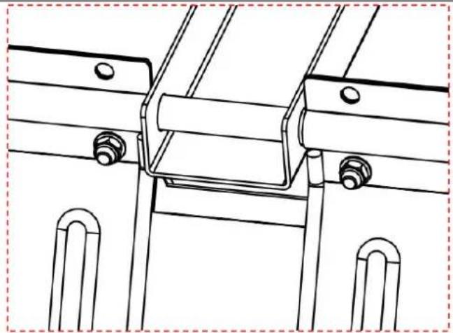
natural_image
Technical line drawing of a mechanical assembly with mounting brackets and bolts (no text or symbols)
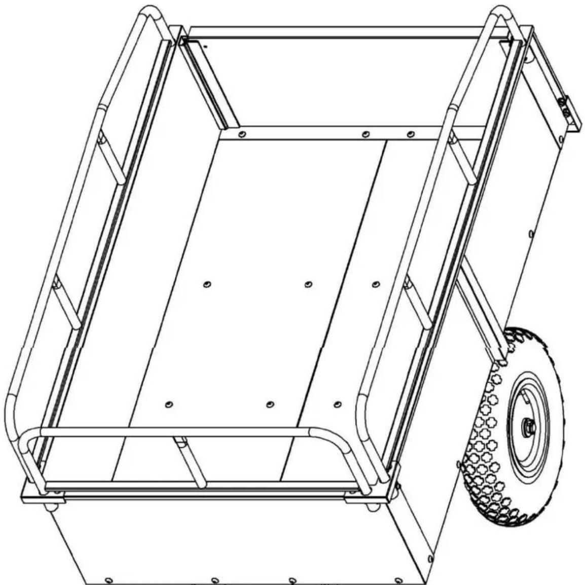
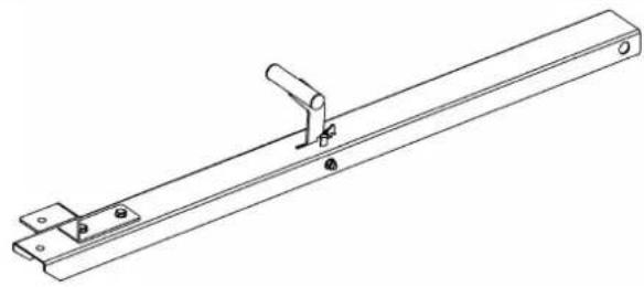
Pass the iron shaft(11) through the slot between the iron plates(10) and insert it into the rod(12) at the middle position.
Caution: The traction rod must be installed in the direction shown in the diagram.
Step 12
natural_image
Technical line drawings of three mechanical components: a cylindrical shaft, a flanged nut, and a hexagonal bolt (no text or symbols)
natural_image
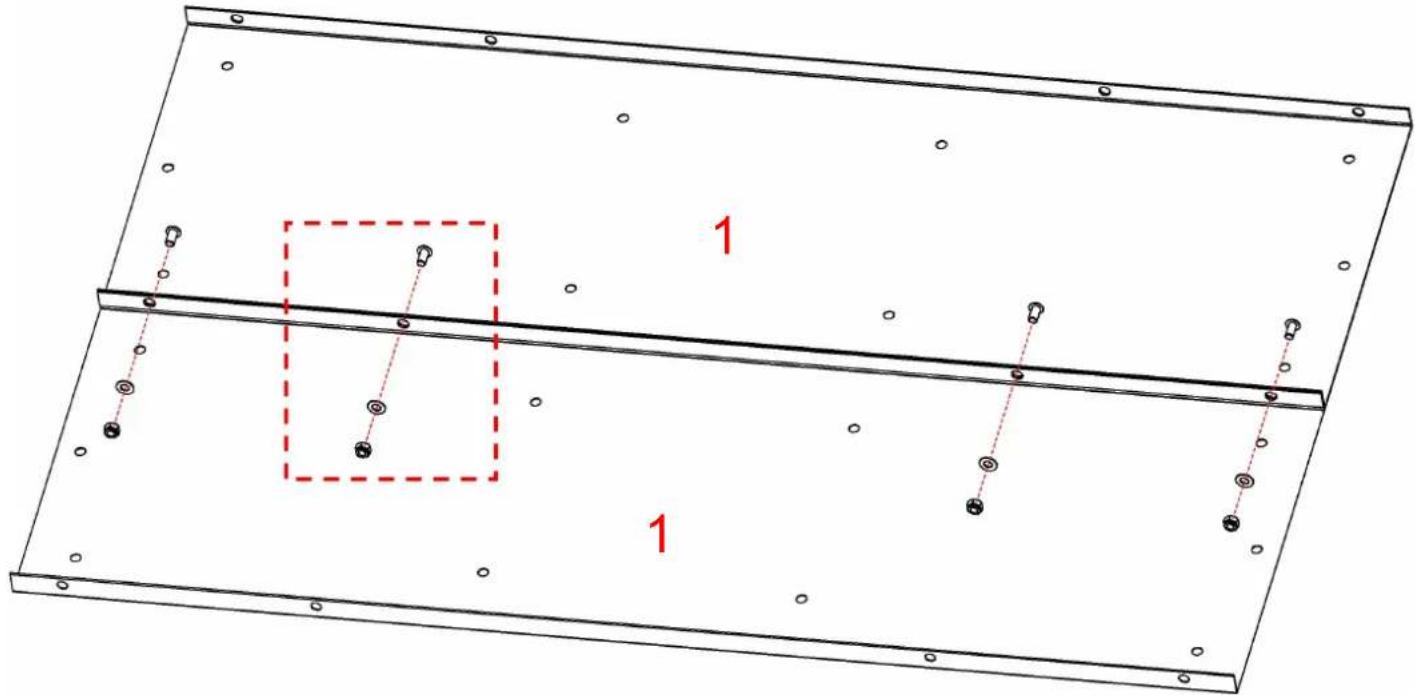
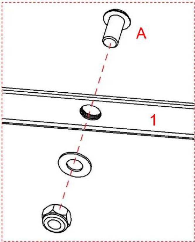
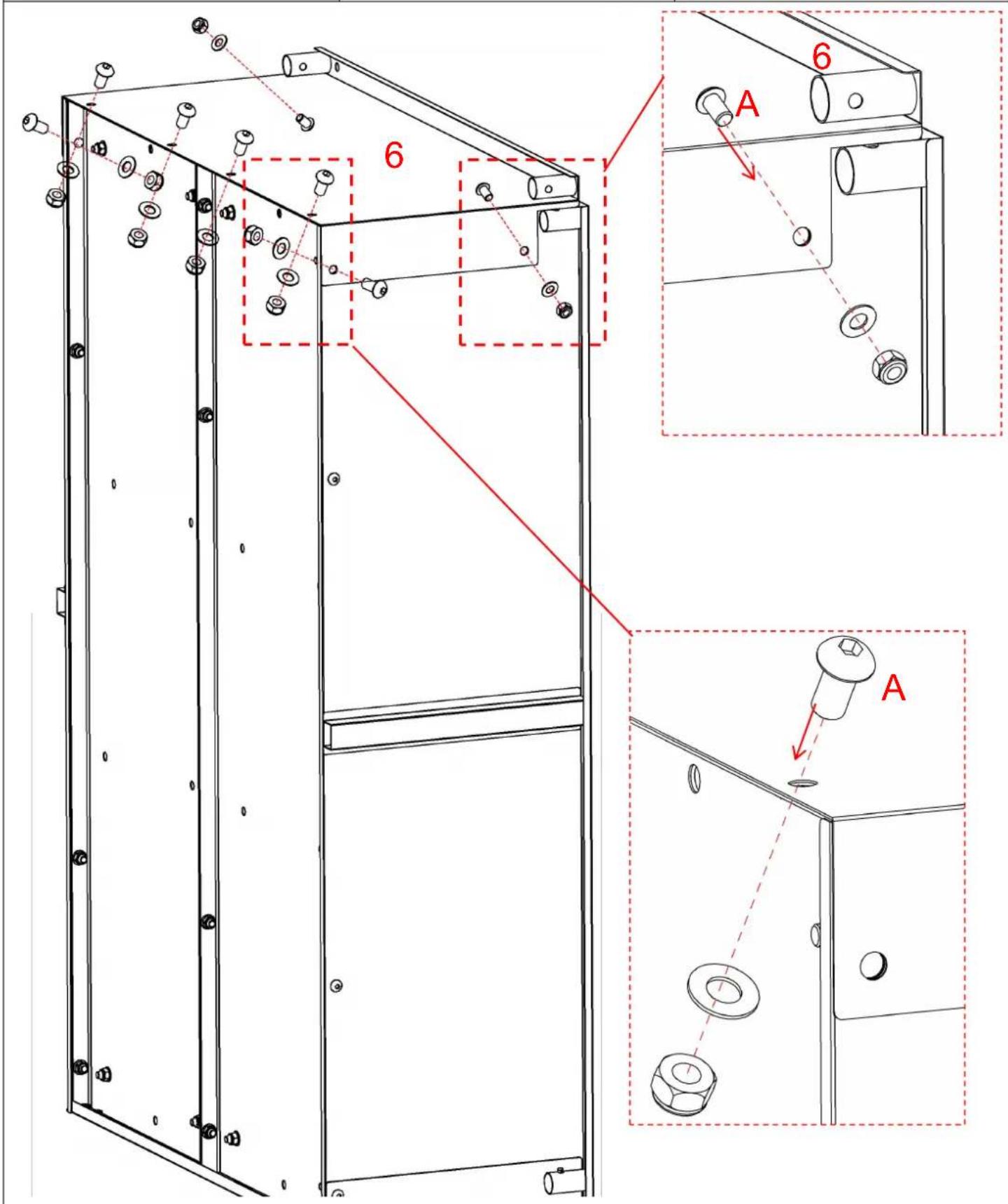
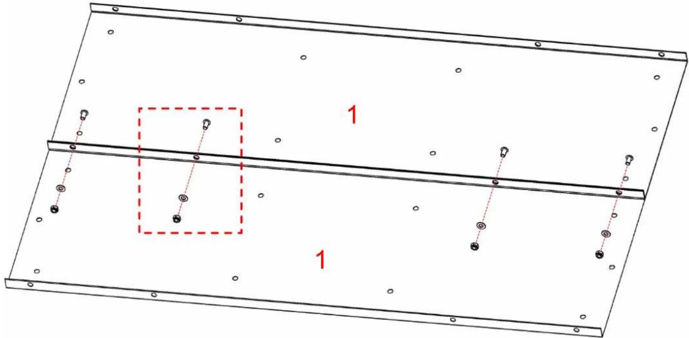
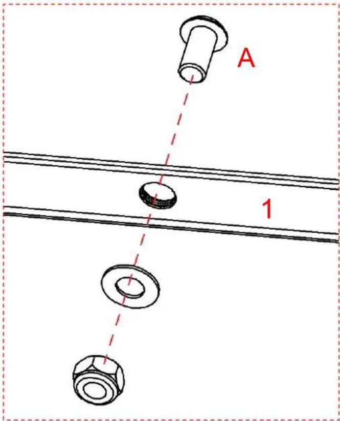
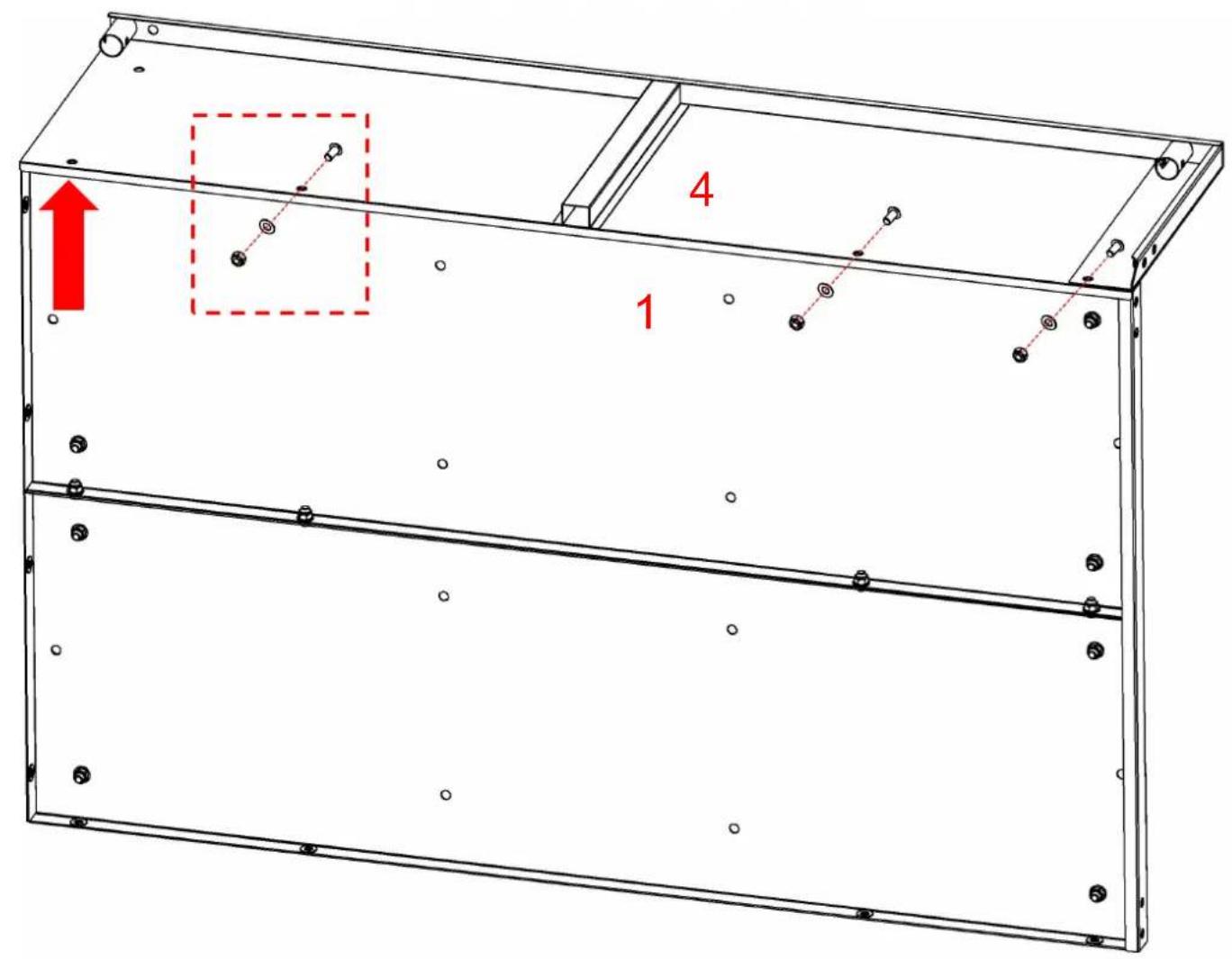
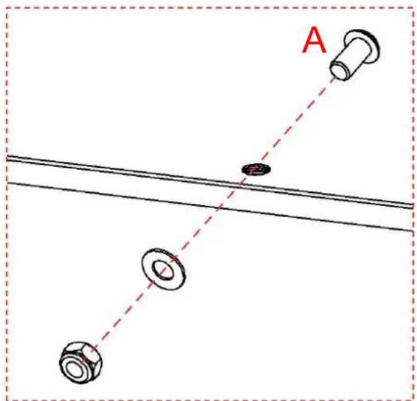
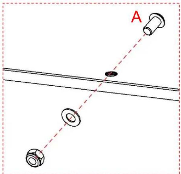
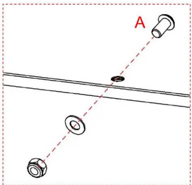
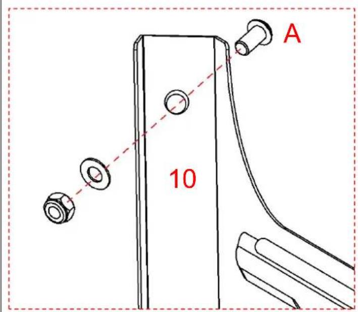
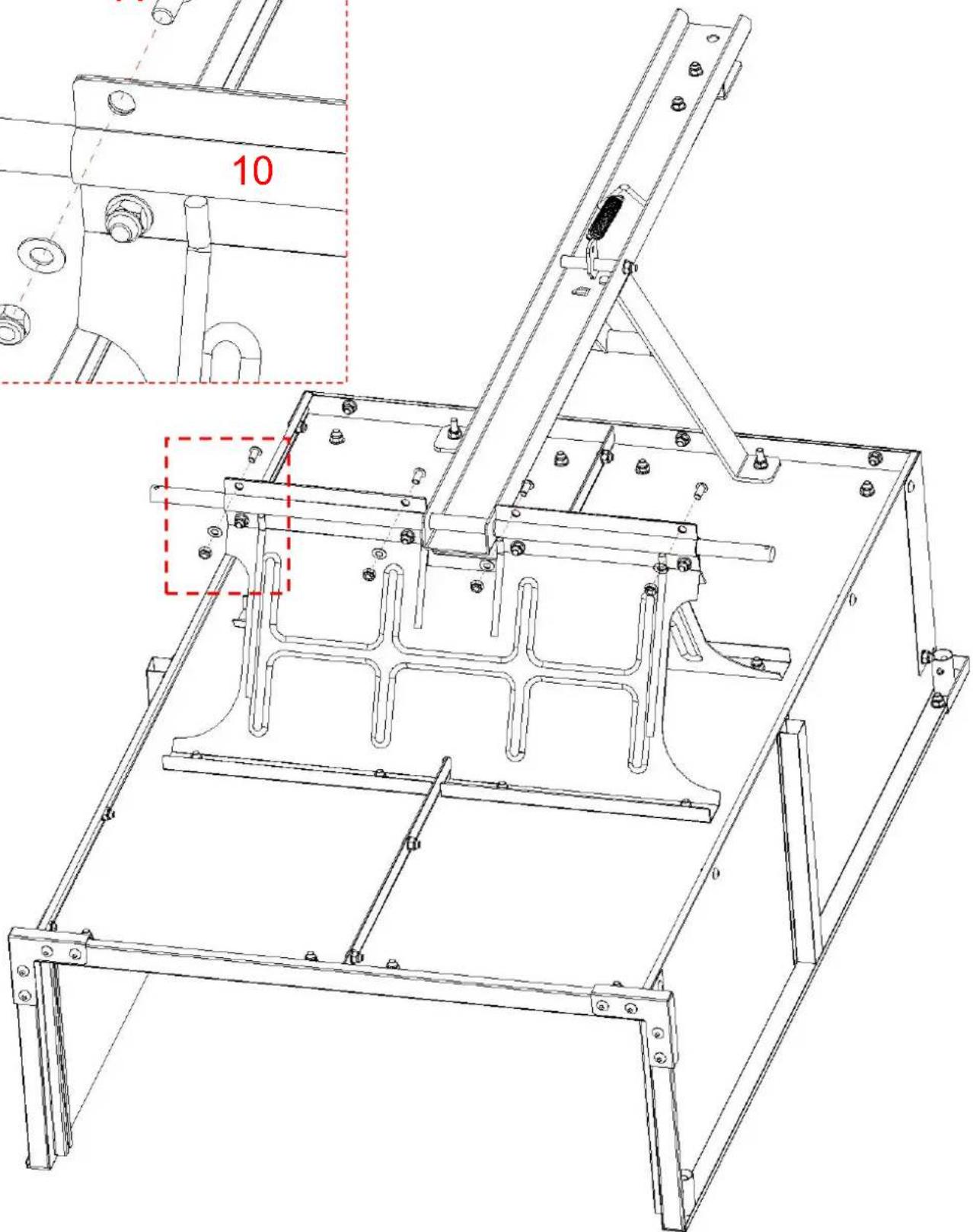
Technical line drawing of a mechanical frame assembly with mounting brackets and a red dashed box highlighting a component (no text or symbols present)When fixing and connecting the two iron plate(10)s, fasten the remaining 4 screw holes screws(A).
Caution: Do not tighten the screws here for the time being; they are reserved to be tightened in subsequent steps.
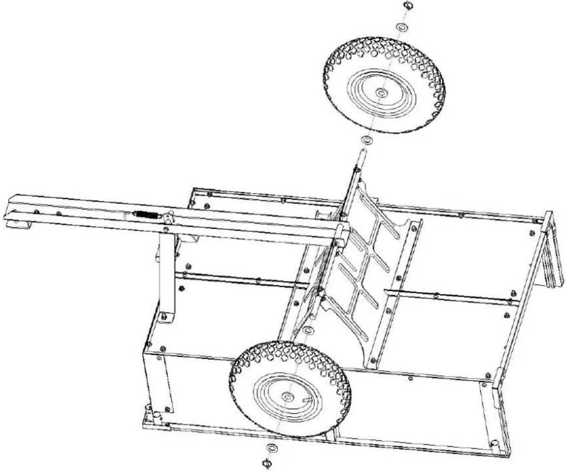
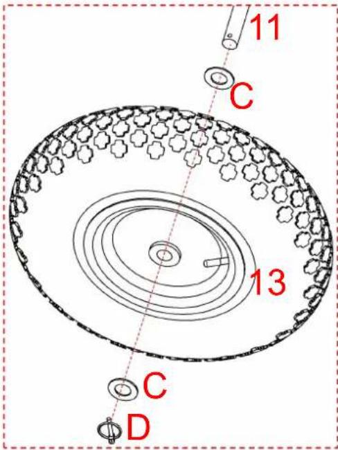
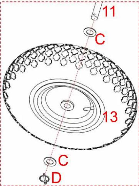
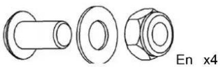
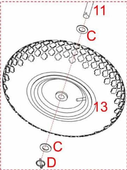
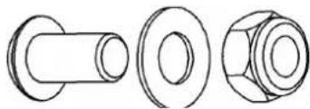
| Step 13 | 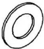 C x4 C x4 |  |
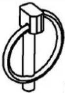 D x2 D x2 | ||
 | ||
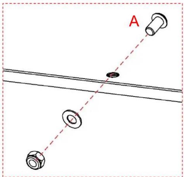
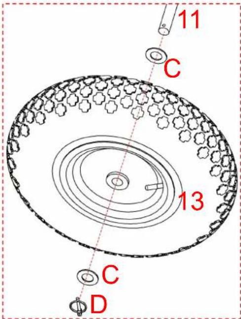 | Please install the components on the axle(11) in th following order: first, fit the washer(C); next, mount wheel(13); then, fit another washer(C); and finally, ir the O-pin(D) to secure them. | |
Step 14
natural_image
Technical line drawings of three mechanical components: a cylindrical bolt, a flanged nut, and a hexagonal bolt (no text or symbols)
Please fully tighten all 16 screws that secure the iron plate(10).
Step 15
natural_image
Technical line drawing of a mechanical component with curved ends and a horizontal bar (no text or symbols)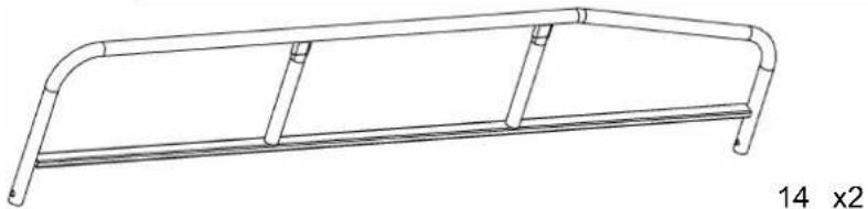
natural_image
Line drawing of a metal frame structure with two curved ends and vertical supports (no text or symbols)
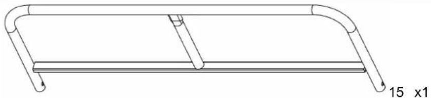
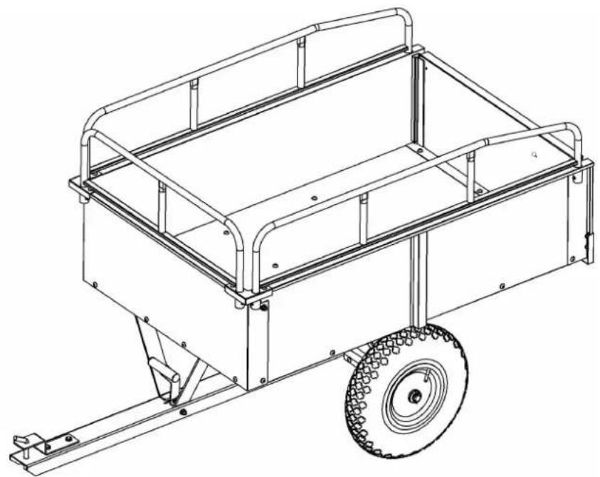
Please accurately insert the guardrail(14;15) into the mounting hole on the side.
Step 16
natural_image
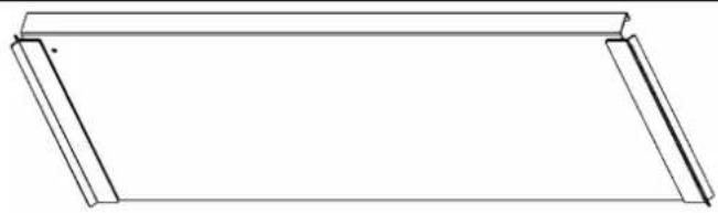
Simple line drawing of a rectangular frame with two side slats (no text or symbols)16 x1
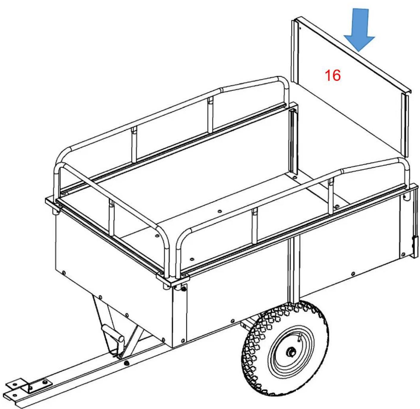
Please accurately insert the tail plate(16) into the mounting slot on the side.
Step 18
F x1
natural_image
Technical line drawing of a wheeled cart with a wheel, showing structural components and mounting holes (no text or symbols)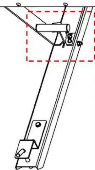
natural_image
Technical line drawing of a mechanical linkage or support structure (no text or symbols)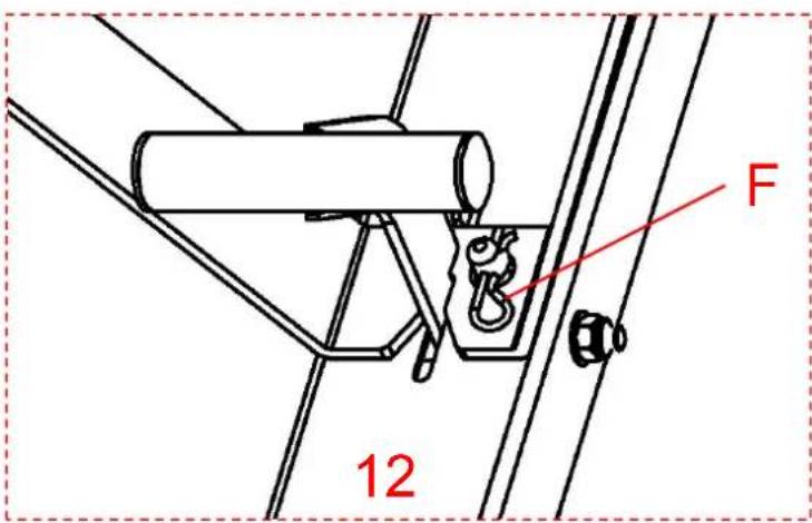
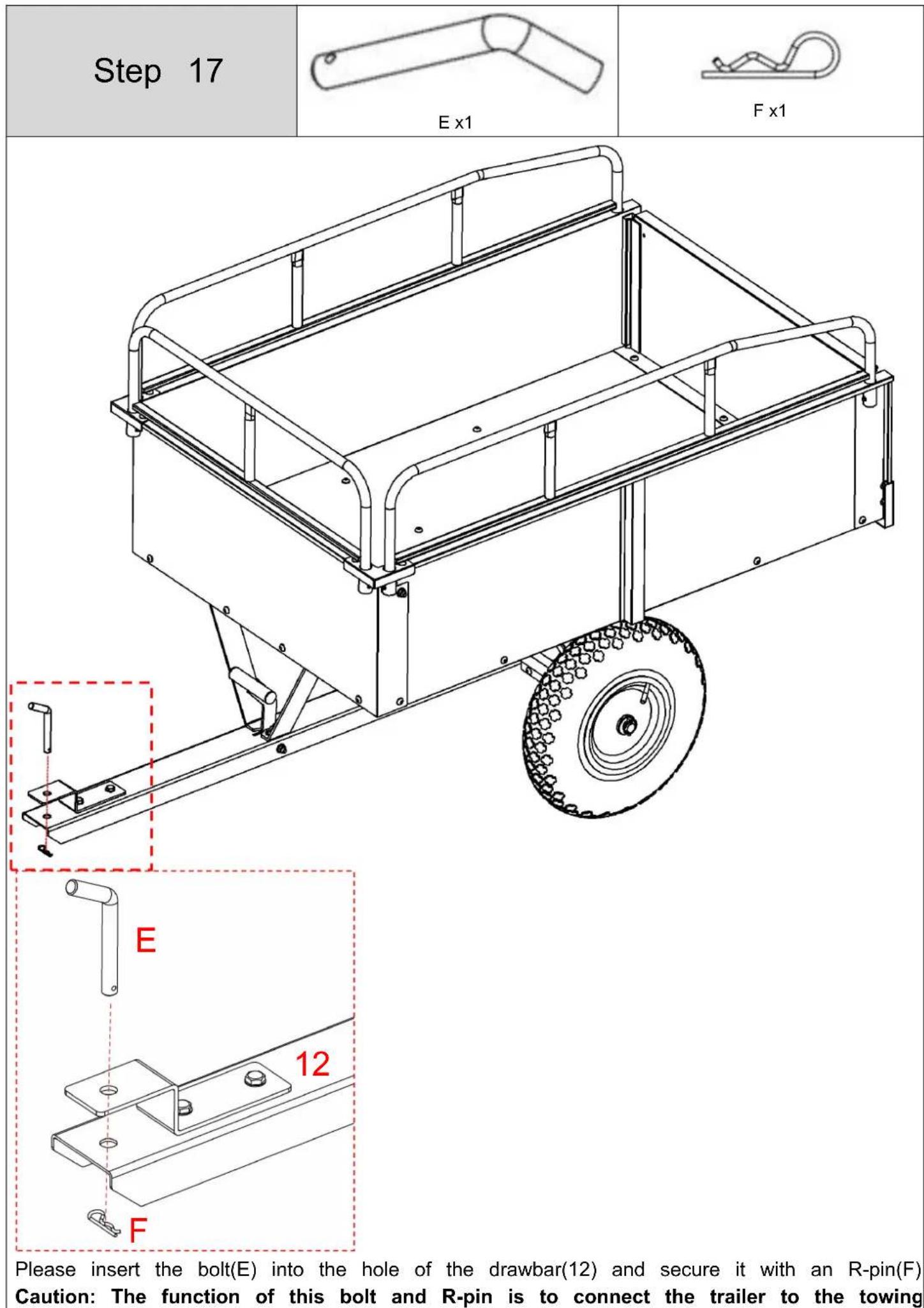
Insert the R-pin(F) into the corresponding hole of the drawbar(12).
Caution: he core function of this R-pin is to firmly lock the opening-closing device trailer towing phase, preventing the opening-closing device from accidentally popping due to road bumps, vibrations, etc. during transportation, thereby ensuring the safety stability of the towing and transportation process.
PRODUCT PARAMETER
| Model | BTC002C |
| Volume | 12ft^3 15ft^3 |
| Carriage size | 1170*760*500mm |
| Maximum loading capacity | 750LBS |
Address: Shuangchenglu 803nong11hao1602A-1609shi, baoshanqu, shanghai 200000 CN.
EC REP: E-CrossStu GmbH.
Mainzer Landstr.69, 60329 Frankfurt am Main.
UK REP: YH CONSULTING LIMITED.
C/O YH Consulting Limited Office 147, Centurion House, London Road, Staines-upon-Thames,
Surrey, TW18 4AX
Imported to AUS: SIHAO PTY LTD.
1 ROKEVA STREETEASTWOOD NSW 2122 Australia
Imported to USA: Sanven Technology Ltd.
Suite 250, 9166 Anaheim Place, Rancho Cucamonga, CA 91730

VEVOR
Affordable. Reliable. Home Improvement.
GARTENANHÄNGER
MODELL : BTC002C
MODELL: BTC002C
natural_image
Technical line drawing of a wheeled cart with railings and a tire, no text or symbols present
https://youtu.be/kmog4Ez0O8k
ASSEMBLY STEP
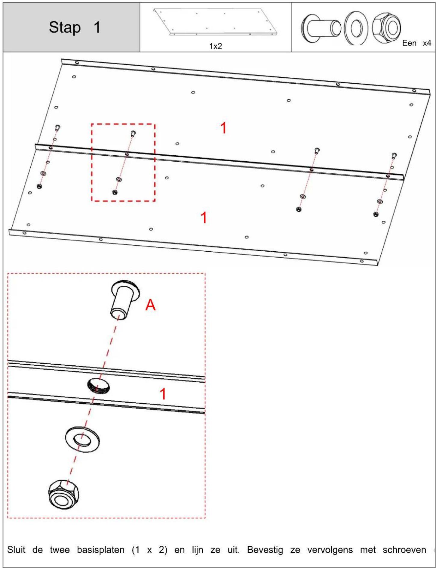
Schritt 1
natural_image
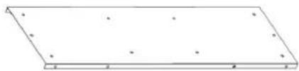
Simple 3D rectangular plate with evenly spaced small dots on both sides (no text or symbols)1 x2
natural_image
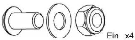
Three technical line drawings of mechanical components: a cylindrical bolt, a flanged nut, and a hexagonal bolt (no text or symbols)Ein x4

natural_image
Simple line drawing of a rectangular frame with side markers and a label '5 x1' below (no other text or symbols)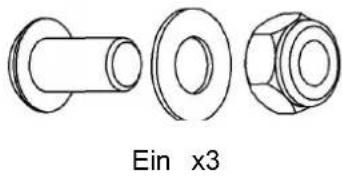
natural_image
Three technical line drawings of a mechanical component, resembling a bolt and nut assembly (no text or symbols)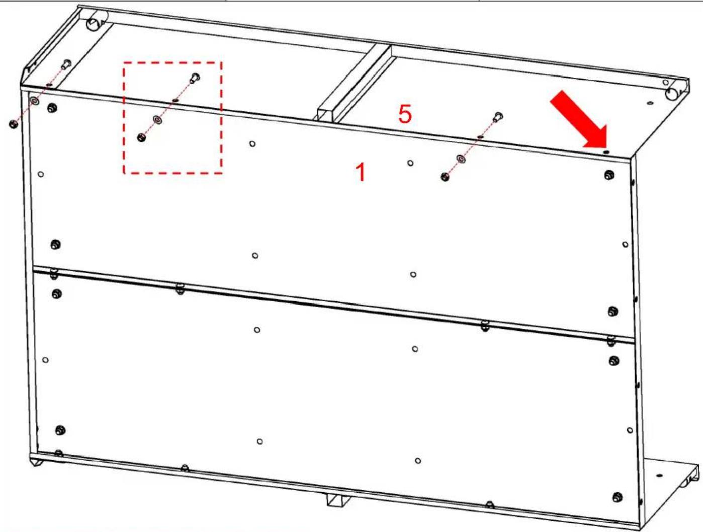

natural_image
Pure technical line drawing of a rectangular frame with mounting holes and no text or symbols6 x1
natural_image
Three technical line drawings of mechanical components: a cylindrical bolt, a flanged nut, and a hexagonal bolt (no text or symbols)Ein x8
natural_image
Technical line drawing of a mechanical bracket assembly with bolts and mounting holes (no text or symbols)Place the iron plate(10) in the direction s in the diagram, align it at the middle pos and then fix it to the base plate with sc
Caution: Do not tighten the screws her the time being; they are reserved to be tightened in subsequent steps.
Schritt 10
natural_image
Three technical drawings of a mechanical component: a cylindrical pin, a flanged nut, and a hexagonal bolt (no text or symbols)
natural_image
Technical line drawing of a mechanical frame assembly with mounting brackets and internal channels (no text or symbols)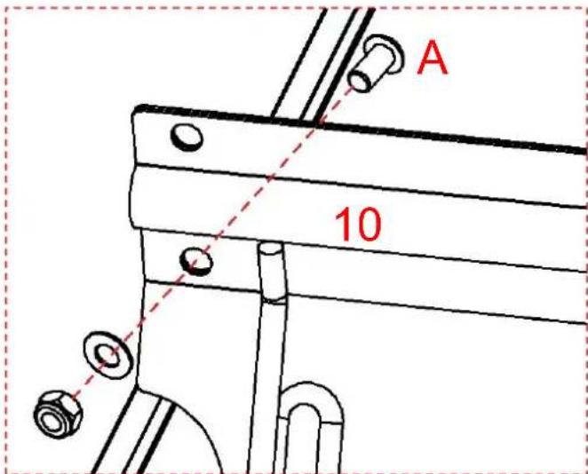
-
Securely connect the two iron plates(10) v screws(A).
-
Caution: There are a total of 8 screw ho here. At this stage, only the 4 lower ones to be tightened, and the remaining holes reserved for tightening in subsequent steps
-
Caution: Do not tighten the screws here, the time being; they are reserved to be fit tightened in subsequent steps.
Schritt 11

natural_image
Technical line drawing of a mechanical bracket with mounting holes and a lever (no text or symbols)12 x1

natural_image
Simple line drawing of a cylindrical object with a small circular mark and the label '11 x1' (no text or symbols on the object itself)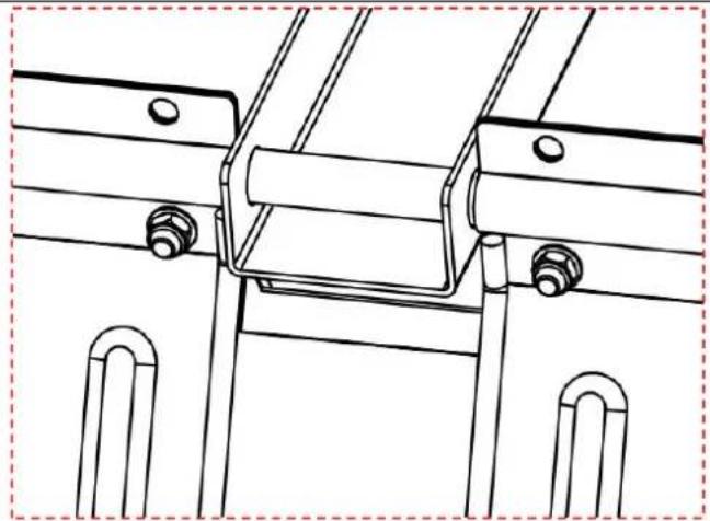
natural_image
Technical line drawing of a mechanical assembly with mounting brackets and bolts (no text or symbols)
natural_image
Three technical drawings of a mechanical component with no visible text or symbols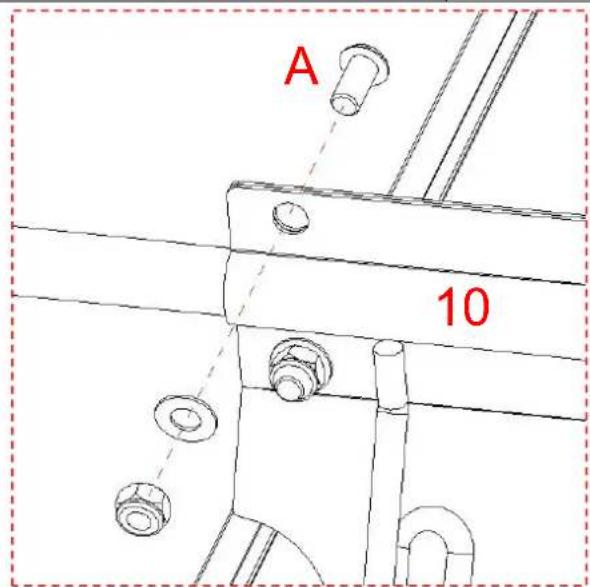

| Schritt 13 |  C x4 C x4 | 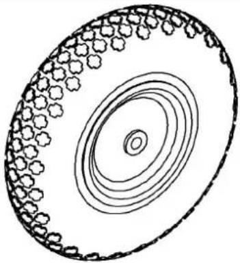 |
 D x2 D x2 | ||
 | ||
 | Please install the components on the axle(11) in th following order: first, fit the washer(C); next, mount wheel(13); then, fit another washer(C); and finally, ir the O-pin(D) to secure them. | |
Schritt 14
natural_image
Three technical drawings of a mechanical component: a cylindrical pin, a flange with a central hole, and a hexagonal nut (no text or symbols)
natural_image
Technical line drawing of a mechanical component with curved ends and a horizontal bar (no text or symbols)
natural_image
Line drawing of a metal frame structure with two curved ends and horizontal supports (no text or symbols)
natural_image
Simple line drawing of a rectangular frame with two side slats and a label '16 x1' at the bottom (no other text or symbols)
C/O YH Consulting Limited Office 147, Centurion House, London Road, Staines-upon-Thames, Surrey, TW18 4AX
Suite 250, 9166 Anaheim Place, Rancho Cucamonga, CA 9173 0

VEVOR
Affordable. Reliable. Home Improvement.
REMORQUE DE JARDIN
MODÈLE : BTC002C
MODÈLE: BTC002C

natural_image
Technical line drawing of a wheeled cart with a wheel, showing frame structure and mounting brackets (no text or symbols)
https://youtu.be/kmog4Ez0O8k
ASSEMBLY STEP
Étape 1
natural_image
Simple 3D rectangular plate with evenly spaced small holes, no text or symbols present1 x 2

natural_image
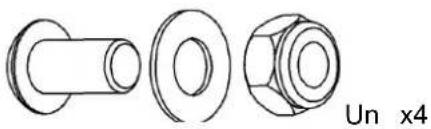
Three technical line drawings of mechanical components: a cylindrical bolt, a flanged nut, and a hexagonal bolt (no text or symbols)Un x4
natural_image
Pure technical line drawing of a rectangular frame with mounting holes and a side tab (no text or symbols)4 × 1
natural_image
Three technical line drawings of mechanical components: a cylindrical bolt, a flanged nut, and a hexagonal bolt (no text or symbols)Un x3
natural_image
Pure technical line drawing of a rectangular frame with mounting holes and dimension lines (no text or symbols)6 x 1
natural_image
Three technical line drawings of a mechanical component: a cylindrical bolt, a flanged nut, and a hexagonal bolt (no text or symbols)Un x8
natural_image
Technical line drawing of a three-legged metal bracket with mounting holes (no text or symbols)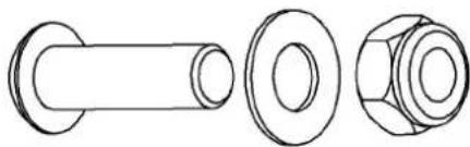
natural_image
Technical line drawings of three mechanical components: a cylindrical shaft, a flanged bolt, and a hexagonal nut (no text or symbols)B x2
Place the iron plate(10) in the direction s in the diagram, align it at the middle pos and then fix it to the base plate with sc
Caution: Do not tighten the screws her the time being; they are reserved to be tightened in subsequent steps.
| Étape 10 | Un x4 |

natural_image
Technical line drawing of a mechanical frame assembly with mounting brackets and internal channels (no text or symbols)
-
Securely connect the two iron plates(10) v screws(A).
-
Caution: There are a total of 8 screw h here. At this stage, only the 4 lower ones to be tightened, and the remaining holes reserved for tightening in subsequent steps
-
Caution: Do not tighten the screws here, the time being; they are reserved to be fit tightened in subsequent steps.
Étape 11

natural_image
Technical line drawing of a mechanical bracket with mounting holes and a central rod (no text or symbols)12 x 1


natural_image
Technical line drawing of a mechanical assembly with mounting brackets and bolts (no text or symbols)
natural_image
Technical line drawing of three mechanical components: a cylindrical bolt, a flanged nut, and a hexagonal bolt (no text or symbols)

| Étape 13 | C x4 | |
| D x2 | ||
| ||
| Please install the components on the axle(11) in th following order: first, fit the washer(C); next, mount wheel(13); then, fit another washer(C); and finally, ir the O-pin(D) to secure them. | |
Étape 14
natural_image
Technical line drawings of three mechanical components: a cylindrical shaft, a flanged circular part, and a hexagonal bolt head (no text or symbols)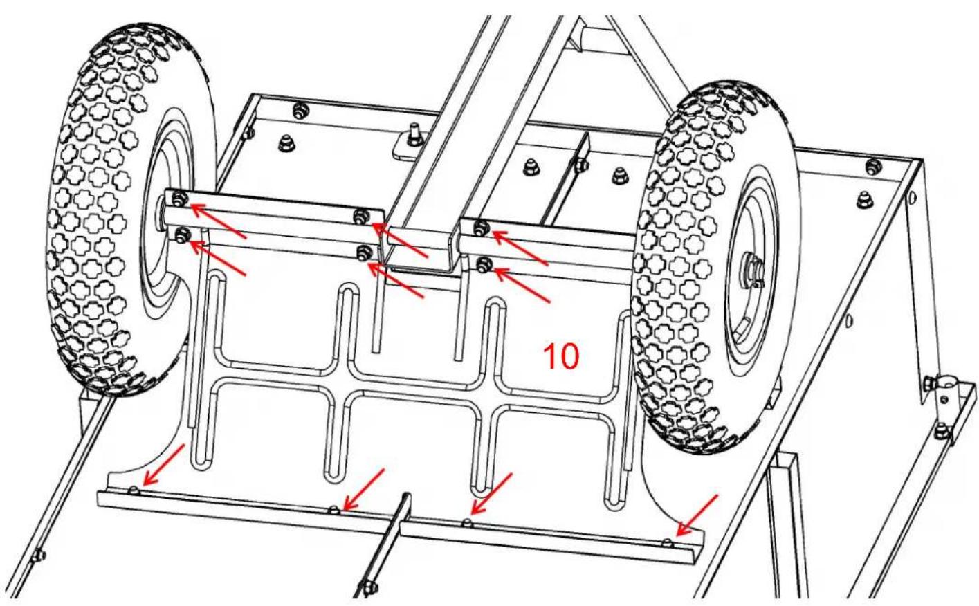
natural_image
Technical line drawing of a mechanical component with two curved ends and a central rod (no text or symbols)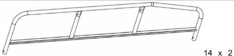
natural_image
Line drawing of a metal frame structure with two curved ends and vertical supports (no text or symbols)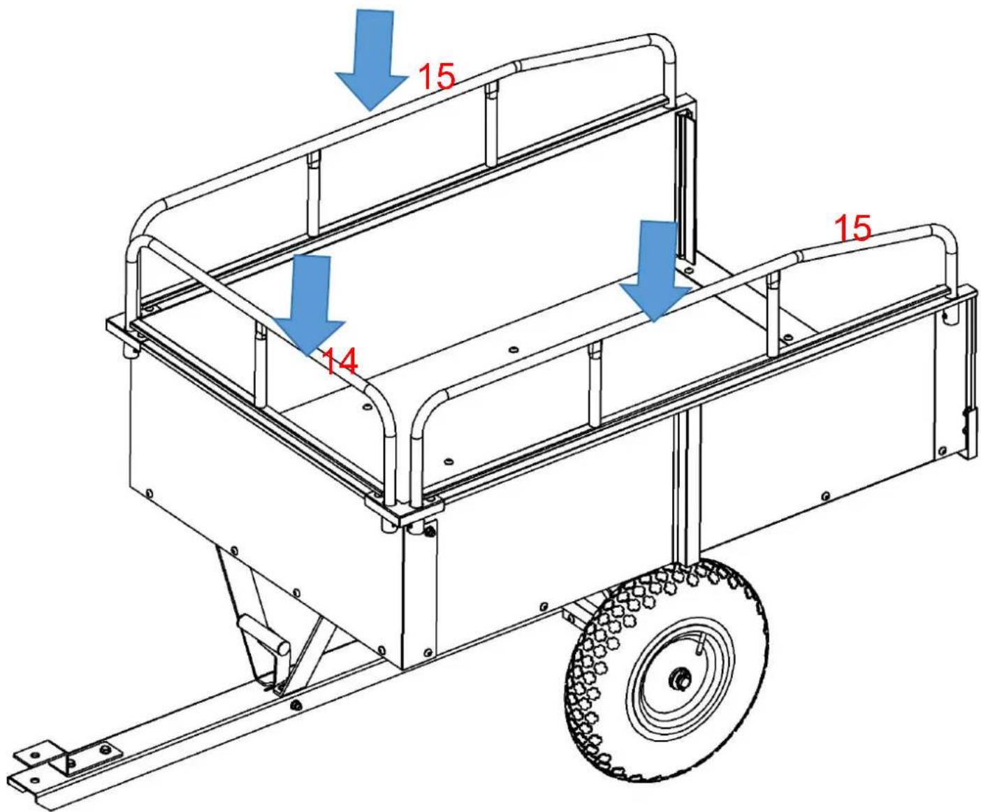
natural_image
Simple line drawing of a rectangular frame with two side slats and a label '16 x 1' on the right side (no other text or symbols)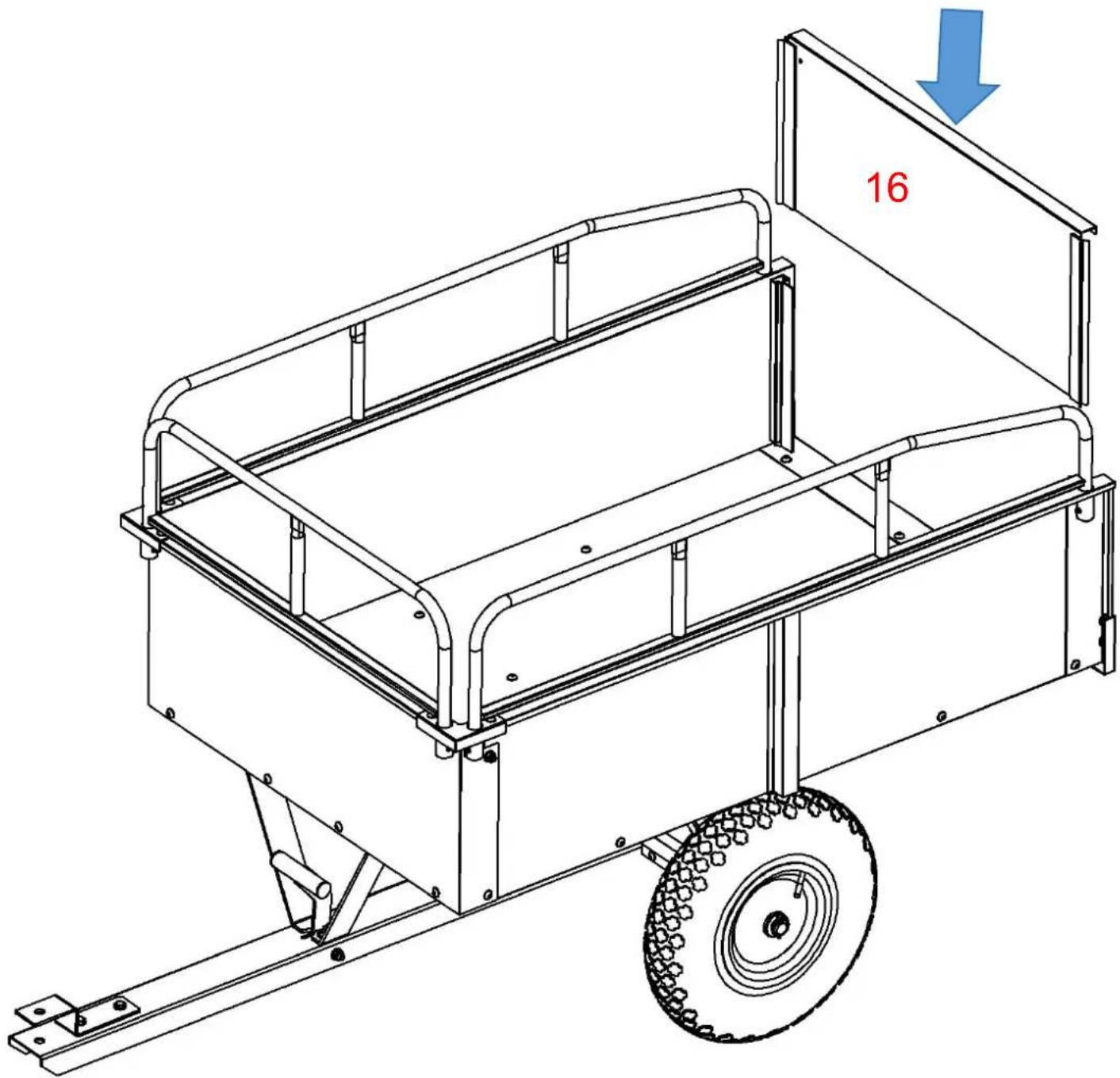
natural_image
Technical line drawing of a wheeled cart with a pull bar and wheel, showing no text or symbolsA/S YH Consulting Limited Bureau 147, Centurion House, London Road, Staines-upon-Thames, Surrey, TW18 4AX
Importé en AUS : SIHAO PTY LTD.
1 ROKEVA STREET, EASTWOOD, NSW 2122, Australie
Suite 250, 9166 Anaheim Place, Rancho Cucamonga, CA 9173 0

VEVOR
Affordable. Reliable. Home Improvement.
TUINAANHANGWAGEN
MODEL : BTC002C
MODEL: BTC002C

natural_image
Technical line drawing of a wheeled cart with a wheel, showing frame structure and mounting brackets (no text or symbols)
https://youtu.be/kmog4Ez0O8k
ASSEMBLY STEP
Place the iron plate(10) in the direction s in the diagram, align it at the middle pos and then fix it to the base plate with sc
Caution: Do not tighten the screws her the time being; they are reserved to be tightened in subsequent steps.
natural_image
Technical line drawing of a mechanical frame assembly with mounting brackets and internal channels (no text or symbols)
-
Securely connect the two iron plates(10) v screws(A).
-
Caution: There are a total of 8 screw h here. At this stage, only the 4 lower ones to be tightened, and the remaining holes reserved for tightening in subsequent steps
-
Caution: Do not tighten the screws here, the time being; they are reserved to be fit tightened in subsequent steps.
Stap 11

natural_image
Technical line drawing of a mechanical bracket with mounting holes and a central rod (no text or symbols)12 x 1

natural_image
Simple line drawing of a cylindrical object with a small circular mark and the label '11 x1' (no text or symbols on the object itself)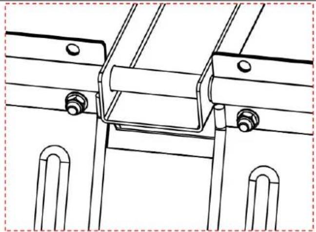
natural_image
Technical line drawing of a mechanical assembly with mounting brackets and bolts (no text or symbols)
natural_image
Technical line drawing of a mechanical frame assembly with mounting brackets and a red dashed box highlighting a section (no text or symbols present)| Stap 13 |  C x4 C x4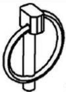 D x2 D x2 | 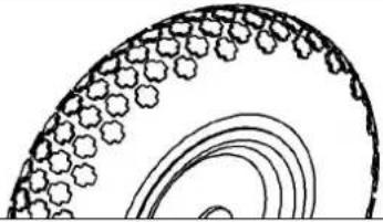 |
  Please install the components on the axle(11) in th following order: first, fit the washer(C); next, mount wheel(13); then, fit another washer(C); and finally, ir the O-pin(D) to secure them. Please install the components on the axle(11) in th following order: first, fit the washer(C); next, mount wheel(13); then, fit another washer(C); and finally, ir the O-pin(D) to secure them. | ||
| Stap 14 | 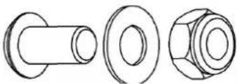 Een x4 Een x4 | |

natural_image
Pure technical line drawing of a mechanical component with no text or symbols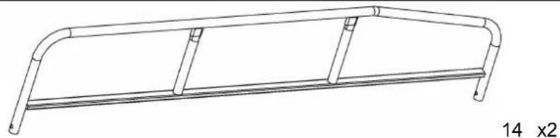
natural_image
Line drawing of a metal-framed horizontal beam with rounded ends and vertical supports (no text or symbols)
natural_image
Simple line drawing of a rectangular frame with two side slats and a label '16 x1' on the right side (no other text or symbols)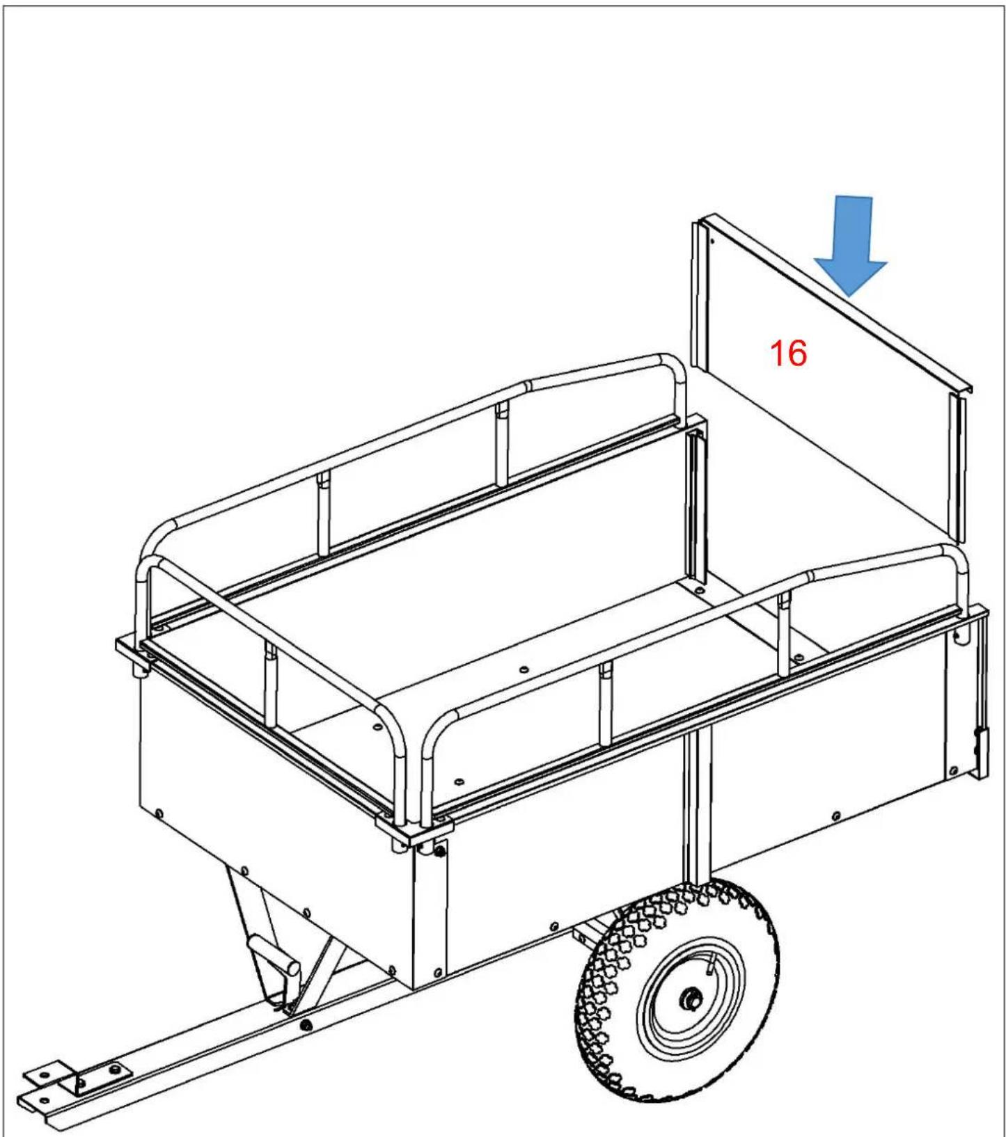
T.a.v. YH Consulting Limited Kantoor 147, Centurion House, London Road, Staines-upon-Thames
Surrey, TW18 4AX
Suite 250, 9166 Anaheim Place, Rancho Cucamonga, CA 9173 0

VEVOR
Affordable. Reliable. Home Improvement.
TRÄDGÅRDSVAGN
MODELL : BTC002C
MODELL: BTC002C

natural_image
Technical line drawing of a wheeled cart with a wheel, showing frame structure and mounting brackets (no text or symbols)
https://youtu.be/kmog4Ez0O8k
ASSEMBLY STEP

natural_image
Line drawing of a three-legged metal bracket with mounting holes and a 9x1 overall size label (no text or symbols on the bracket itself)
natural_image
Technical line drawings of three mechanical components: a cylindrical shaft, a flanged bolt, and a hexagonal nut (no text or symbols)B x2

Place the iron plate(10) in the direction s in the diagram, align it at the middle pos and then fix it to the base plate with sc
Caution: Do not tighten the screws her the time being; they are reserved to be tightened in subsequent steps.

natural_image
Technical line drawing of a mechanical frame assembly with mounting brackets and internal channels (no text or symbols)
-
Securely connect the two iron plates(10) v screws(A).
-
Caution: There are a total of 8 screw I here. At this stage, only the 4 lower ones to be tightened, and the remaining holes reserved for tightening in subsequent steps
-
Caution: Do not tighten the screws here, the time being; they are reserved to be fit tightened in subsequent steps.
Steg 11

natural_image
Technical line drawing of a mechanical bracket with mounting holes and a central rod (no text or symbols)12 x 1


natural_image
Technical line drawing of a mechanical assembly with mounting brackets and bolts (no text or symbols)
natural_image
Technical line drawing of three mechanical components: a cylindrical shaft, a flanged nut, and a hexagonal bolt (no text or symbols)

| Steg 13 | C x4 | |
| D x2 | ||
| ||
| Please install the components on the axle(11) in th following order: first, fit the washer(C); next, mount wheel(13); then, fit another washer(C); and finally, ir the O-pin(D) to secure them. | |
Steg 14
natural_image
Technical line drawings of three mechanical components (cylindrical, flange, and nut) with no text or symbols
natural_image
Technical line drawing of a mechanical component with curved ends and a central rod (no text or symbols)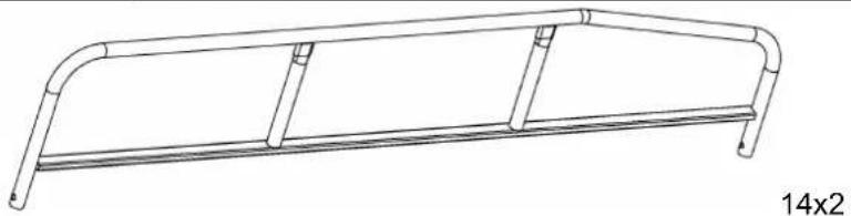
natural_image
Line drawing of a metal frame structure with two curved ends and a flat base, labeled '14x2' (no text or symbols on the diagram itself)
natural_image
Simple line drawing of a rectangular frame with two side slats and a top edge, labeled '16 x 1' at the bottom (no other text or symbols)
natural_image
Technical line drawing of a wheeled cart with a wheel, showing structural components and mounting holes (no text or symbols)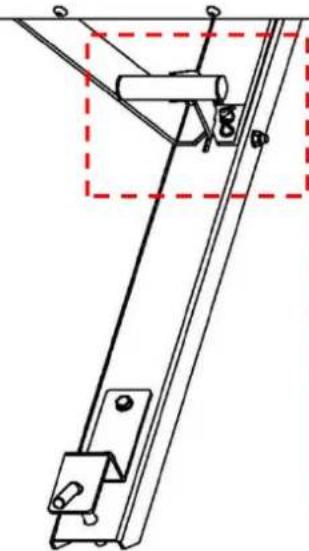
natural_image
Technical line drawing of a mechanical linkage or bracket assembly (no text or symbols)
C/O YH Consulting Limited Kontor 147, Centurion House, London Road, Staines-upon-Thames,
Surrey, TW18 4AX
Importerad till Australien: SIHAO PTY LTD.
1 ROKEVA STREETEASTWOOD NSW 2122 Australien
Importerad till USA: Sanven Technology Ltd.
Svit 250, 9166 Anaheim Place, Rancho Cucamonga, CA 9173 0

VEVOR
Affordable. Reliable. Home Improvement.
REMOLQUE DE JARDÍN
MODELO : BTC002C
MODELO: BTC002C

natural_image
Technical line drawing of a wheeled cart with a wheel, showing frame structure and mounting brackets (no text or symbols)
https://youtu.be/kmog4Ez0O8k
ASSEMBLY STEP
Paso 1
natural_image
Simple 3D rectangular plate with evenly spaced small dots on both sides (no text or symbols)1 x 2

natural_image
Three technical line drawings of a mechanical component: a cylindrical bolt, a flanged nut, and a hexagonal bolt (no text or symbols)Un x4

natural_image
Pure technical line drawing of a rectangular frame with mounting holes and internal ribs (no text or symbols)4x1
natural_image
Three technical line drawings of mechanical components: a cylindrical bolt, a flanged nut, and a hexagonal bolt (no text or symbols)A x3

Alinee el panel lateral (4) con la placa base (1) y fijelos con los tornillos (A).
natural_image
Pure technical line drawing of a rectangular frame with mounting holes and side markers (no text or symbols)5x1
natural_image
Three technical line drawings of a mechanical component: a cylindrical bolt, a flanged nut, and a hexagonal bolt (no text or symbols)A x3
Alinee el panel lateral (5) con la placa base (1) y fijelos con los tornillos (A).
natural_image
Technical line drawing of a mechanical bracket assembly with bolts and mounting holes (no text or symbols)natural_image
Technical line drawing of a mechanical bracket assembly (no text or symbols)2
natural_image
Three technical line drawings of mechanical components: a cylindrical bolt, a flanged nut, and a hexagonal bolt (no text or symbols)Un x8
Place the iron plate(10) in the direction s in the diagram, align it at the middle pos and then fix it to the base plate with sc
Caution: Do not tighten the screws her the time being; they are reserved to be tightened in subsequent steps.
Paso 10
natural_image
Technical line drawings of three mechanical components: a cylindrical part, a flanged circular part, and a hexagonal bolt head (no text or symbols)
natural_image
Technical line drawing of a mechanical frame assembly with mounting brackets and internal channels (no text or symbols)
- Securely connect the two iron plates(10) screws(A).
- Caution: There are a total of 8 screw I here. At this stage, only the 4 lower ones to be tightened, and the remaining holes reserved for tightening in subsequent steps
- Caution: Do not tighten the screws here, the time being; they are reserved to be fit tightened in subsequent steps.
Paso 11
natural_image
Technical line drawing of a mechanical bracket with mounting holes and a central rod (no text or symbols)12 x 1


natural_image
Technical line drawing of a mechanical assembly with mounting brackets and bolts (no text or symbols)
natural_image
Technical line drawing of a mechanical frame assembly with mounting brackets and a red dashed box highlighting a section (no text or symbols present)| Paso 13 |  C x4 C x4 D x2 D x2 |  |
 | ||
 | Please install the components on the axle(11) in th following order: first, fit the washer(C); next, mount wheel(13); then, fit another washer(C); and finally, ir the O-pin(D) to secure them. | |
| Paso 14 |  | |
natural_image
Pure technical line drawing of a mechanical component with no text or symbols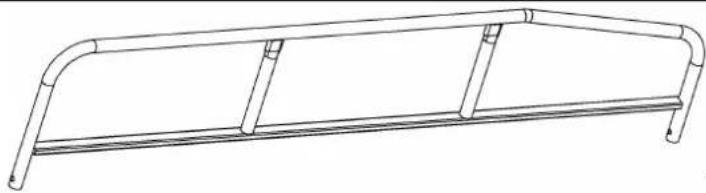
natural_image
Line drawing of a three-legged metal frame structure (no text or symbols)14 × 2

natural_image
Simple line drawing of a rectangular frame with two side slats and a top edge, labeled '16 x 1' at the bottom (no other text or symbols)
C/O YH Consulting Limited Oficina 147, Centurion House, London Road, Staines-upon-Thames,
Surrey, TW18 4AX
Importado a AUS: SIHAO PTY LTD.
1 ROKEVA STREET, EASTWOOD, NSW 2122, Australia
Suite 250, 9166 Anaheim Place, Rancho Cucamonga, CA 9173 0

VEVOR
Affordable. Reliable. Home Improvement.
RIMORCHIO DA GIARDINO
MODELLO : BTC002C
MODELLO: BTC002C

natural_image
Technical line drawing of a wheeled cart with a wheel, showing frame structure and mounting brackets (no text or symbols)
https://youtu.be/kmog4Ez0O8k
ASSEMBLY STEP
Fase 1

natural_image
Simple 3D rectangular plate with evenly spaced small dots on both sides (no text or symbols)1 x2
natural_image
Three technical line drawings of mechanical components: a cylindrical bolt, a flanged nut, and a hexagonal bolt (no text or symbols)Un x4


natural_image
Technical line drawing of a mechanical bracket with two mounting holes and a 9x1 overall detail (no text or symbols)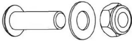
natural_image
Technical line drawings of three mechanical components: a cylindrical shaft, a flanged bolt, and a hexagonal nut (no text or symbols)B x2


Place the iron plate(10) in the direction s in the diagram, align it at the middle pos and then fix it to the base plate with sc
Caution: Do not tighten the screws her the time being; they are reserved to be tightened in subsequent steps.
Fase 10
natural_image
Three technical line drawings of a mechanical component, showing cylindrical, flanged, and threaded parts (no text or symbols)
natural_image
Technical line drawing of a mechanical frame assembly with mounting brackets and structural supports (no text or symbols)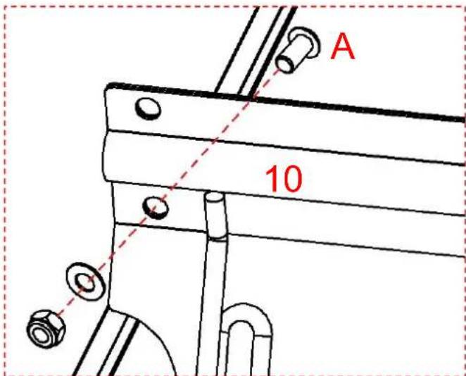
-
Securely connect the two iron plates(10) screws(A).
-
Caution: There are a total of 8 screw I here. At this stage, only the 4 lower ones to be tightened, and the remaining holes reserved for tightening in subsequent steps
-
Caution: Do not tighten the screws here, the time being; they are reserved to be fit tightened in subsequent steps.
Fase 11

natural_image
Technical line drawing of a mechanical bracket with mounting holes and a lever mechanism (no text or symbols)12 x1

natural_image
Simple line drawing of a cylindrical object with a small circular mark and the label '11 x1' (no text or symbols on the object itself)
natural_image
Technical line drawing of a mechanical assembly with bolts and brackets (no text or symbols)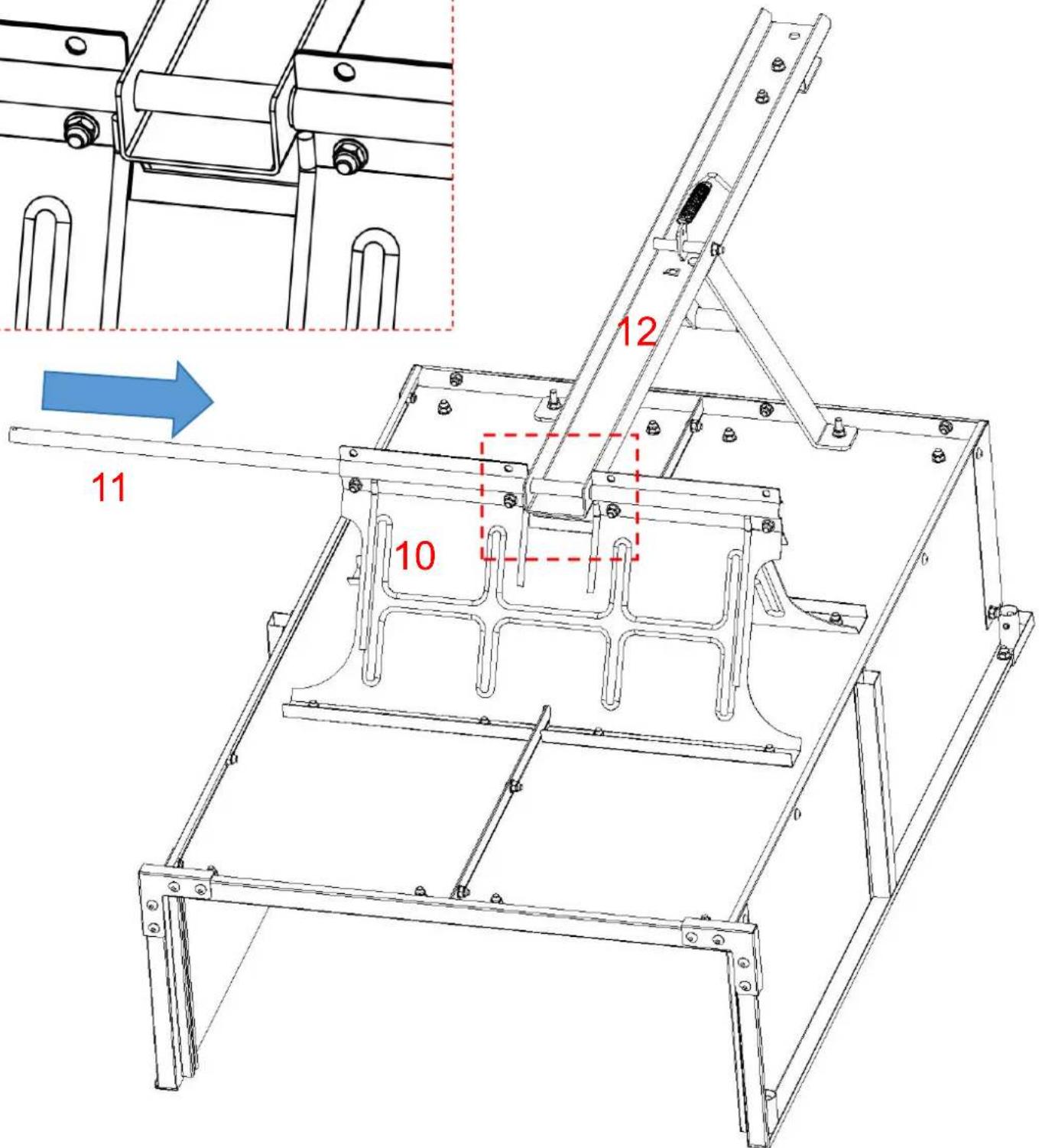
natural_image
Technical line drawing of three mechanical components: a cylindrical bolt, a flanged washer, and a hexagonal nut (no text or symbols)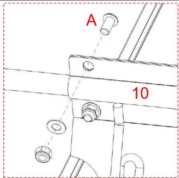
| Fase 13 | C x4 | |
| D x2 | ||
| Please install the components on the axle(11) in th following order: first, fit the washer(C); next, mount wheel(13); then, fit another washer(C); and finally, ir the O-pin(D) to secure them. | ||
Fase 14

natural_image
Technical line drawings of three mechanical components: a cylindrical shaft, a flanged circular part, and a hexagonal bolt head (no text or symbols)
natural_image
Technical line drawing of a mechanical component with curved ends and a horizontal bar (no text or symbols)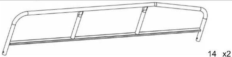
natural_image
Line drawing of a metal frame structure with two curved ends and horizontal supports (no text or symbols)
natural_image
Simple line drawing of a rectangular frame with two side slats and a label '16 x1' at the bottom (no other text or symbols)
C/O YH Consulting Limited Ufficio 147, Centurion House, London Road, Staines-upon-Thames, Surrey, TW18 4AX
Importato in AUS: SIHAO PTY LTD.
1 ROKEVA STREETEASTWOOD NSW 2122 Australia
Suite 250, 9166 Anaheim Place, Rancho Cucamonga, CA 9173 0

VEVOR
Affordable. Reliable. Home Improvement.
PRZYCZEPA OGRODOWA
MODEL : BTC002C
MODEL: BTC002C

natural_image
Technical line drawing of a wheeled cart with a wheel and side railings (no text or symbols)
https://youtu.be/kmog4Ez0O8k
ASSEMBLY STEP
Krok 1
1 x2
x4
1
1
A
1

Place the iron plate(10) in the direction s in the diagram, align it at the middle pos and then fix it to the base plate with sc
Caution: Do not tighten the screws her the time being; they are reserved to be tightened in subsequent steps.

natural_image
Technical line drawing of a mechanical frame assembly with mounting brackets and internal channels (no text or symbols)
-
Securely connect the two iron plates(10) screws(A).
-
Caution: There are a total of 8 screw I here. At this stage, only the 4 lower ones to be tightened, and the remaining holes reserved for tightening in subsequent steps
-
Caution: Do not tighten the screws here, the time being; they are reserved to be fit tightened in subsequent steps.
Krok 11

natural_image
Technical line drawing of a mechanical bracket with mounting holes and a lever mechanism (no text or symbols)12 x1

natural_image
Simple line drawing of a cylindrical object with a small circular mark and the label '11 x1' (no text or symbols on the object itself)
natural_image
Technical line drawing of a mechanical assembly with bolts and brackets (no text or symbols)
natural_image
Three technical line drawings of mechanical components, no text or symbols present

| Krok 13 | C x4 | |
| D x2 | ||
| ||
| Please install the components on the axle(11) in th following order: first, fit the washer(C); next, mount wheel(13); then, fit another washer(C); and finally, ir the O-pin(D) to secure them. | |
Krok 14
natural_image
Three technical line drawings of mechanical components, including a cylindrical shaft, flange, and nut (no text or symbols)
natural_image
Technical line drawing of a mechanical component with curved ends and a horizontal bar (no text or symbols)
natural_image
Line drawing of a metal frame structure with two curved ends and horizontal supports (no text or symbols)
natural_image
Simple line drawing of a rectangular frame with two side slats and a label '16 x1' at the bottom (no other text or symbols)
natural_image
Technical line drawing of a wheeled cart with a wheel, showing structural components and mounting holes (no text or symbols)
natural_image
Technical line drawing of a mechanical linkage or support structure (no text or symbols)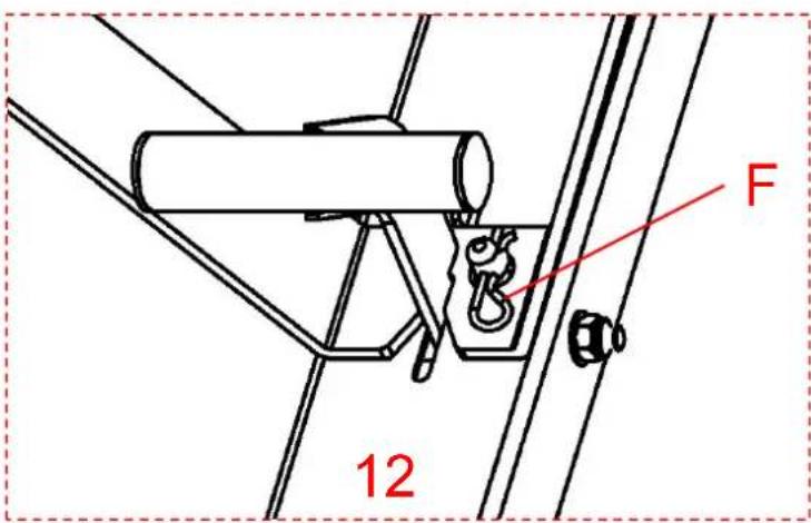
C/O YH Consulting Limited Biuro 147, Centurion House, London Road, Staines-upon-Thames, TW18 4AX
Importowane do AUS: SIHAO PTY LTD.
1 ROKEVA STREETEASTWOOD NSW 2122 Australia
Importowane do USA: Sanven Technology Ltd.
Apartament 250, 9166 Anaheim Place, Rancho Cucamonga, CA 9173 0