TC4288 - Garden trailer Vevor - Free user manual and instructions
Find the device manual for free TC4288 Vevor in PDF.

| Product Type | Folding Garden Trailer |
| Brand | Vevor |
| Model | TC4288 |
| Volume | 28 ft³ (0.79 m³) |
| Dimensions (L x W x H) | 1524 x 810 x 635 mm (60 x 32 x 25 in) |
| Maximum Load Capacity | 1765 lb (800 kg) |
| Frame Material | Painted Steel |
| Wheel Type | 2 solid wheels with tread |
| Guardrails | 4 removable side, front and rear panels |
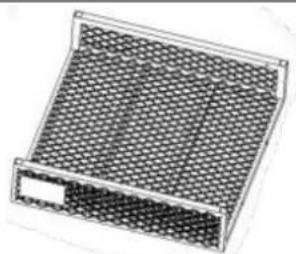
| Protection Mat | Plastic Mat Included |
| Assembly Required | Yes, by 2 people, about 20 minutes |
| Intended Use | Transport of garden materials, tools, etc. |
| Safety Precautions | Do not sit or stand; do not let children play; do not exceed maximum load; use on flat surface |
| Maintenance | Inspect before each use; check tightness of fasteners; clean after use |
| Spare Parts Included | Screws, washers, pins, nuts – spare set provided |
| Repairability | Standard parts available; disassembly possible for repair |
| Warranty | Manufacturer's warranty (see conditions) |
| Manufacturer | Shanghaimuxinmuyeyouxiangongsi, Shanghai, China |
| Importer | Sanven Technology Ltd. (United States); SIHAO PTY LTD (Australia) |
Frequently Asked Questions - TC4288 Vevor
User questions about TC4288 Vevor
0 question about this device. Answer the ones you know or ask your own.
Ask a new question about this device
Download the instructions for your Garden trailer in PDF format for free! Find your manual TC4288 - Vevor and take your electronic device back in hand. On this page are published all the documents necessary for the use of your device. TC4288 by Vevor.
USER MANUAL TC4288 Vevor
Affordable. Reliable. Home Improvement.
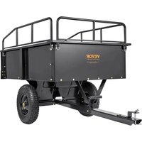
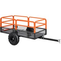
GARDEN TRAILERS
MODEL:TC4268/TC4278/TC4288
MODEL:TC4268/TC4278/TC4288

natural_image
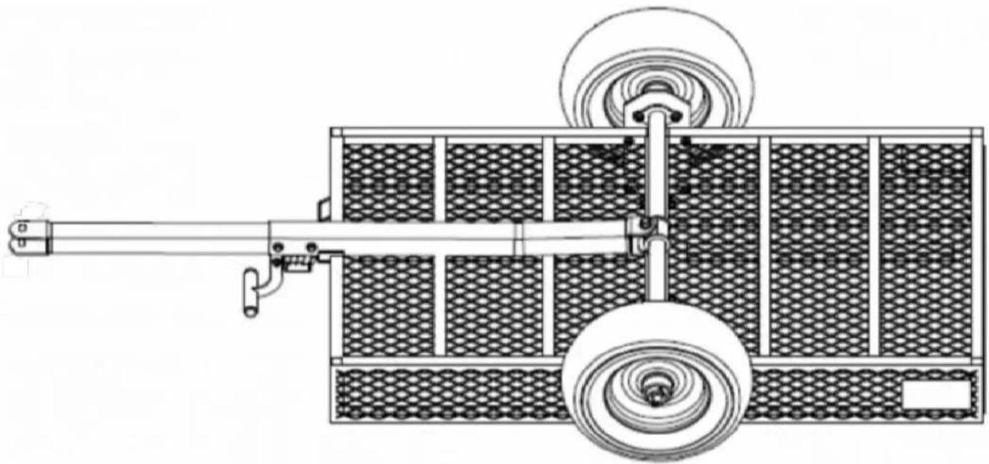
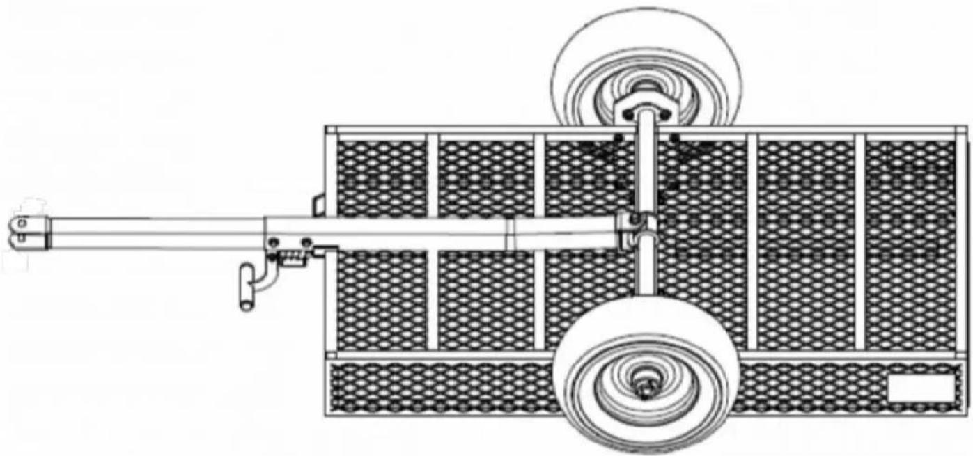
Technical line drawing of a two-wheeled cart with mesh panels and a wheel (no text or symbols)
https://youtu.be/aIQyVCV19sY
For the installation video, please scan the QR code to access.
This is the original instruction, please read all manual instructions carefully before operating. VEVOR reserves a clear interpretation of our user manual. The appeal of the product shall be subject to the product you received. Please forgive us won't inform you again if there are any technology or software updates on our
WARNING:
Read this material before using this product. Failure to do so can result serious injury.
Assembly precautions
- Assemble only according to these instructions. Improper assembly can create hazard
- Wear ANSI-approved safety goggles and heavy-duty work gloves during assembly.
- Keep the assembly area clean and well-lit.
- Keep bystanders out of the area during assembly.
- Do not assemble if tired or when under the influence of alcohol, drugs or medical
- The product capabilities apply to properly and completely assembled products only.
- Assemble on a flat, level, hard and smooth surface capable of safely supporting the Garden Trailer.
- For additional information regarding the parts listed in the following pages, please refer to the Assembly Diagram of this manual. Unwrap and separate all parts in a clean way
- It is estimated that the installation of this product can be completed in 20 minutes person.
- Since a large number of screws are required for assembling this product, we have provided spare screws. Therefore, there is no need to worry if you have any rem screws after completing the product assembly.
Use precautions
- DO NOT SIT OR STAND ON THIS ITEM.
- This product is not a toy. Do not allow children to play with or near this item.
- Do not exceed specified weight capacities.
- Use only on a flat, level, hard, and smooth surface that can safely support a fully Garden Trailer.
- Use as intended only.
- Inspect before every use; do not use if parts are loose or damaged.
SAVE THIS MANUAL
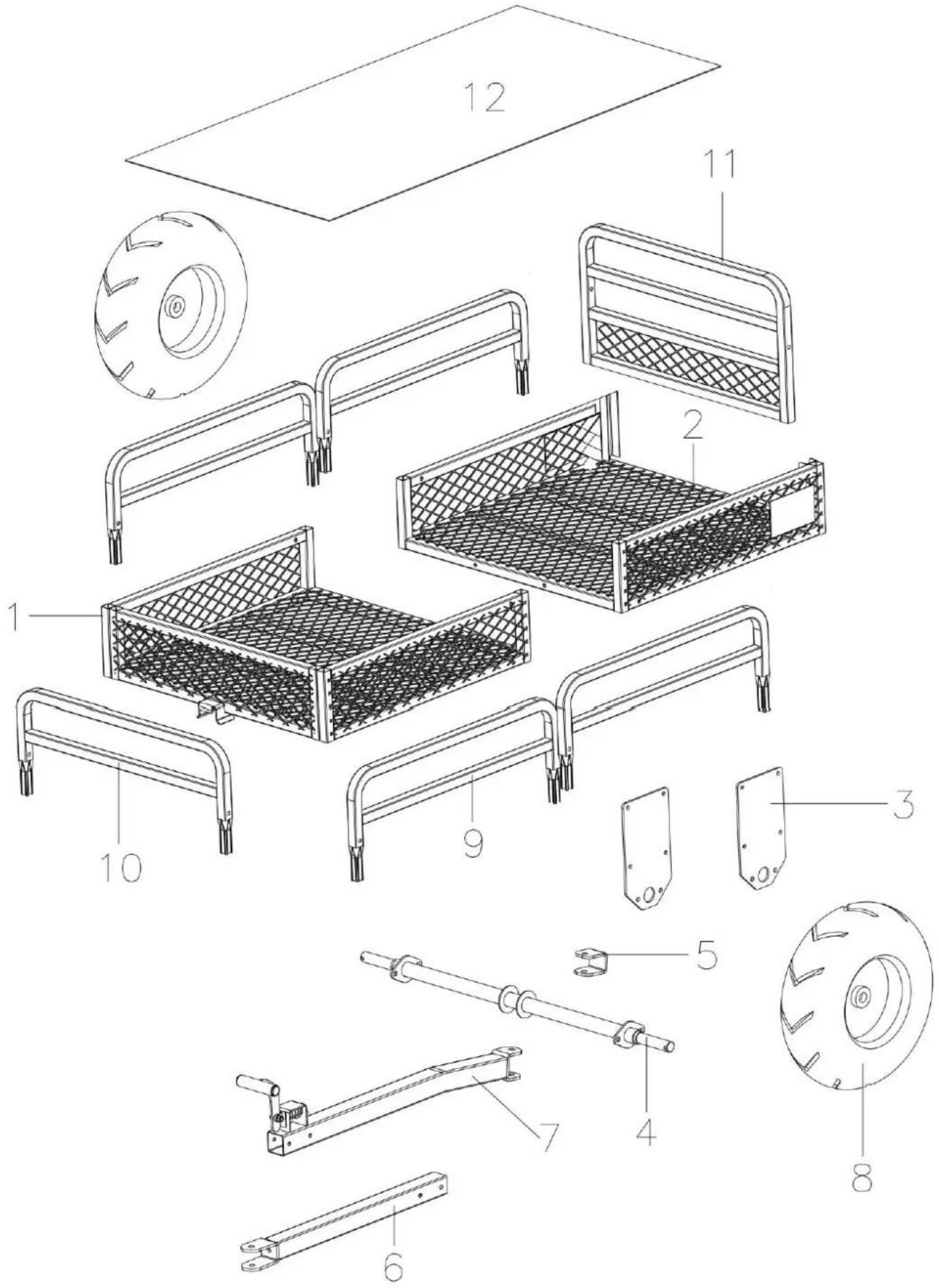
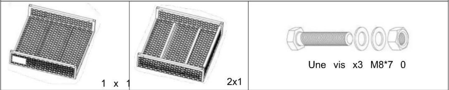
PARTS LIST
| NO. | Explanatory Chart | NO. | Explanatory Chart |
| 1 | 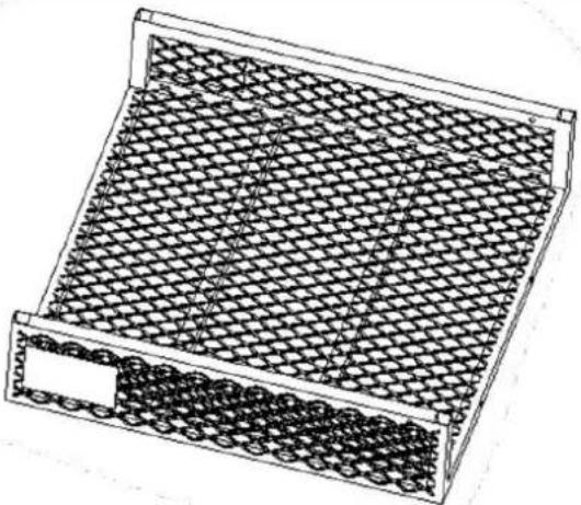 Frame A Frame A | 2 | 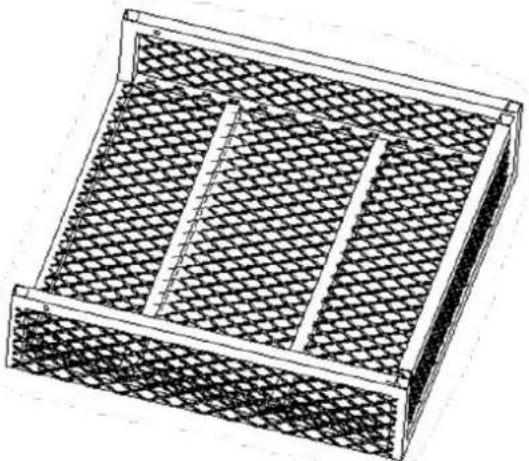 Frame B Frame B |
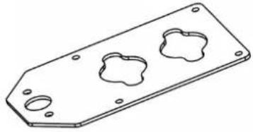
| 3 | 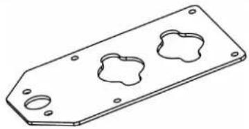 Fixed plate X2 Fixed plate X2 | 4 | 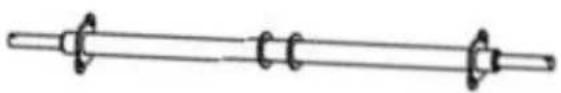 Axle Axle |
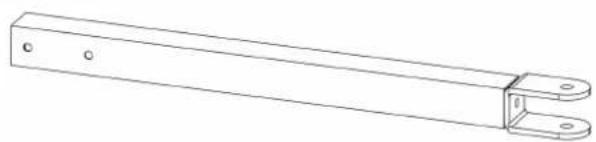
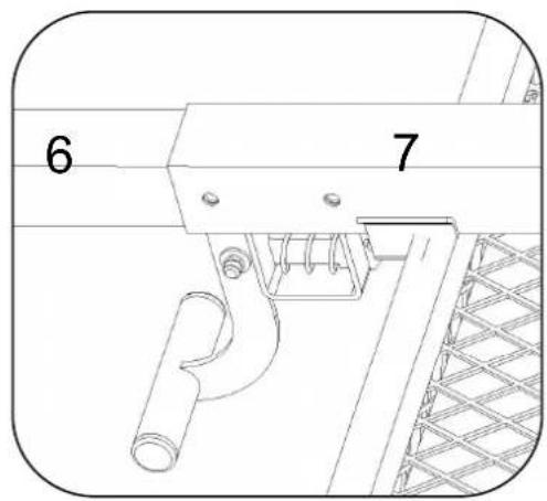
| 5 | 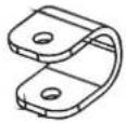 U - shaped part U - shaped part | 6 | 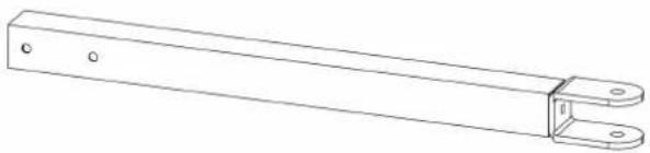 Connecting rod A Connecting rod A |
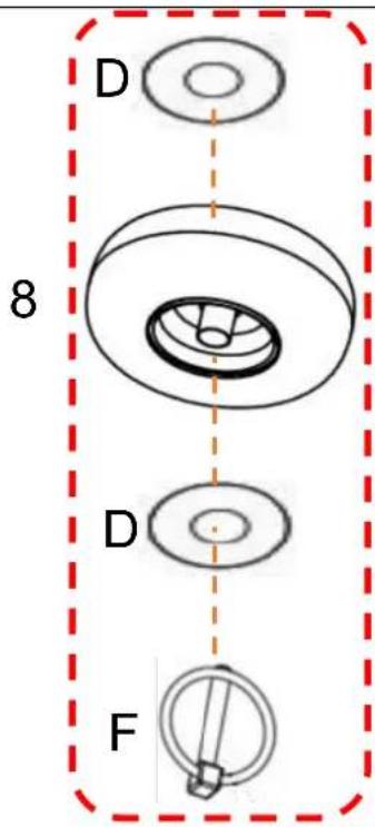
| 7 | 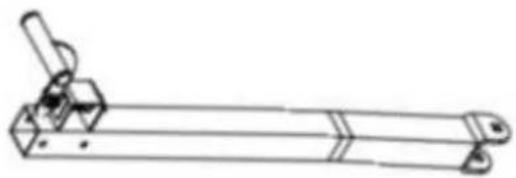 Connecting rod B Connecting rod B | 8 | 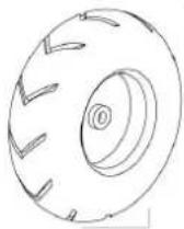 Wheel X2 Wheel X2 |
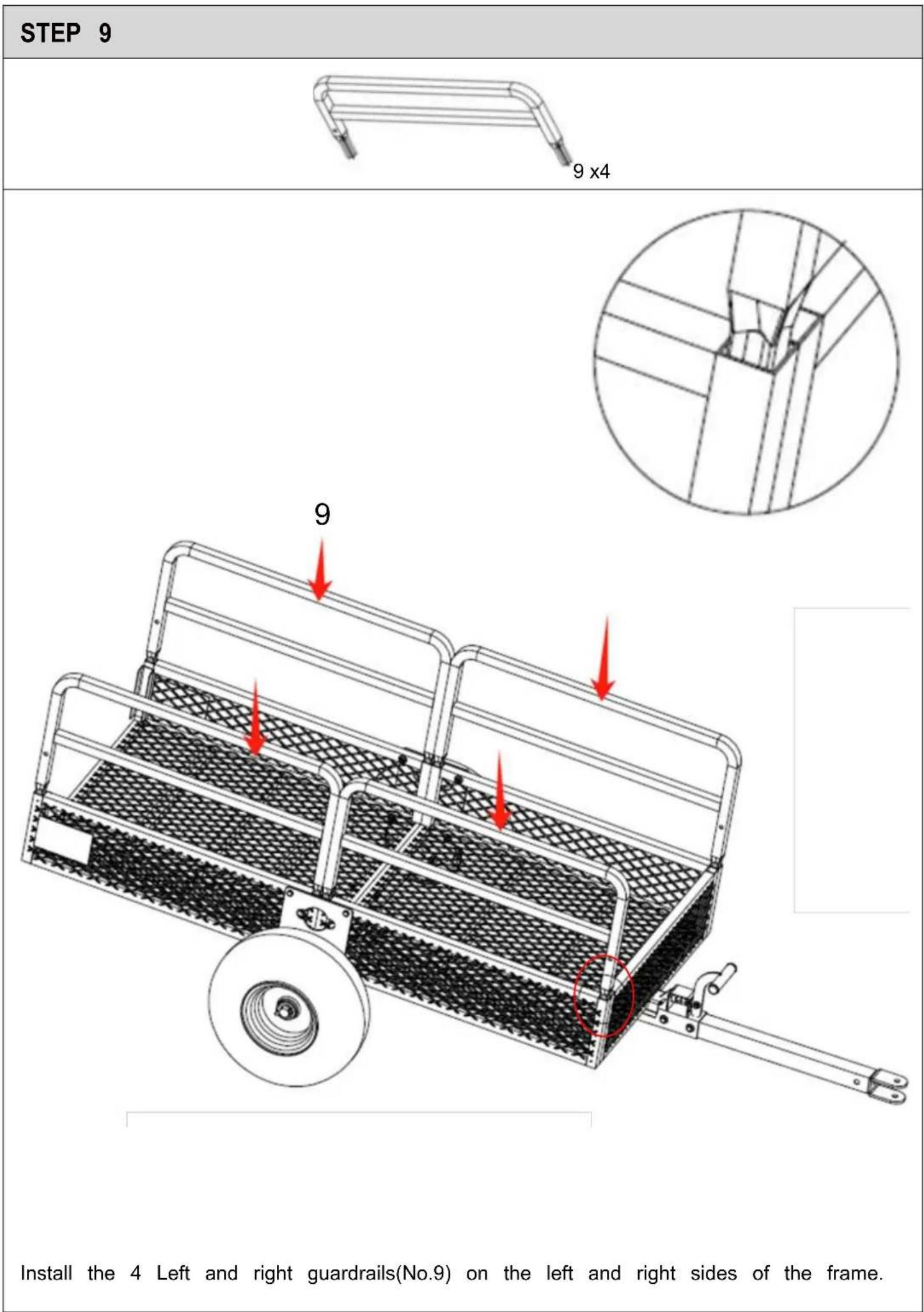
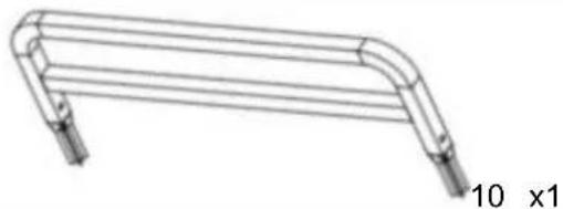
| 9 | 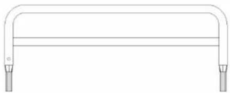 Left and right guardrails X4 Left and right guardrails X4 | 10 | 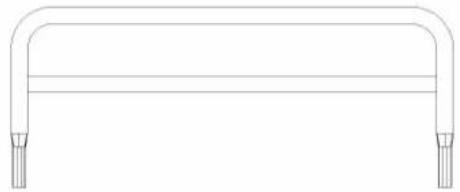 Front guardrail Front guardrail |
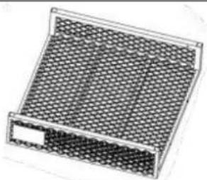
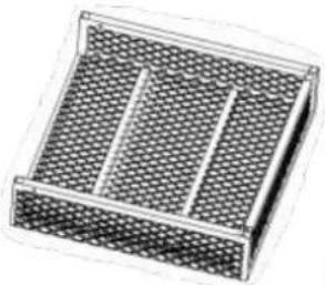
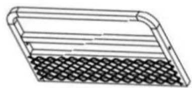
| 11 | 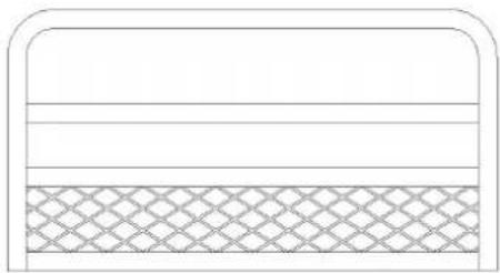 Rear guardrail Rear guardrail | 12 | 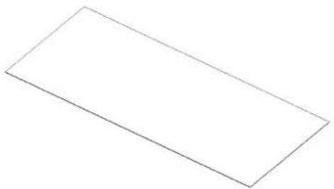 Plastic mat Plastic mat |
| NO. | Explanatory Chart | Quantity |
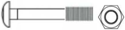
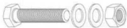
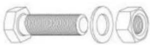
| A | 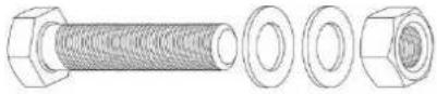 Screw M8*70mm Screw M8*70mm | 5 |
| B | 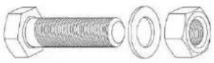 Screw M8*45mm Screw M8*45mm | 8 |
| C | 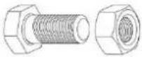 Screw M10*25mm Screw M10*25mm | 4 |
| D | 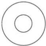 Washer 50*3mm Washer 50*3mm | 4 |
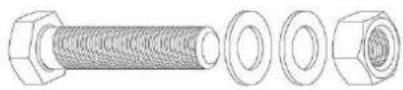
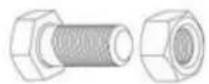
| E | 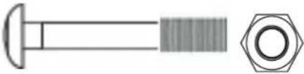 Screw M12*90mm Screw M12*90mm | 1 |
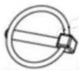
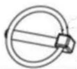
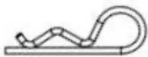
| F | 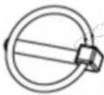 O - type cotter pin O - type cotter pin | 2 |
| G | 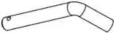 pin pin | 1 |
| H | 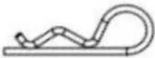 R - type cotter pin R - type cotter pin | 1 |
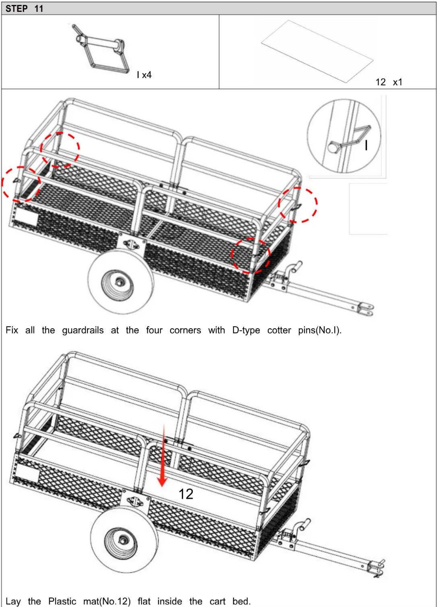
| I | 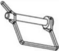 D - type cotter pin D - type cotter pin | 4 |
 x2 x2 | ||
 x1 x1 | ||
ASSEMBLY STEP
STEP 1
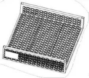
natural_image
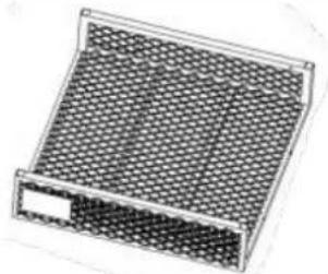
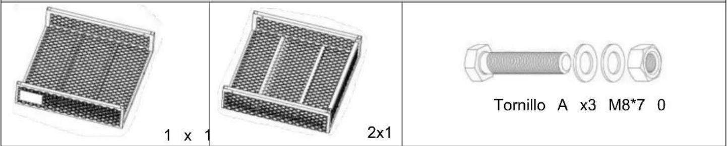
Illustration of a rectangular electronic device with a grid-patterned panel (no text or symbols)1 x 1
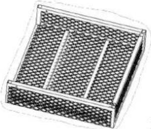
natural_image
Illustration of a rectangular container filled with honeycomb patterns, no text or symbols present2x1
A x3 Screw M8*70
natural_image
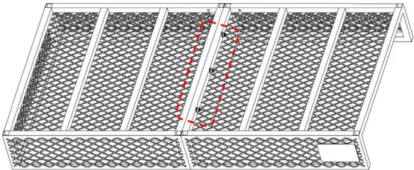
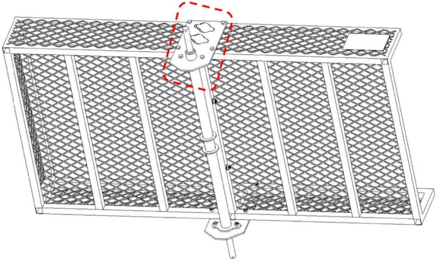
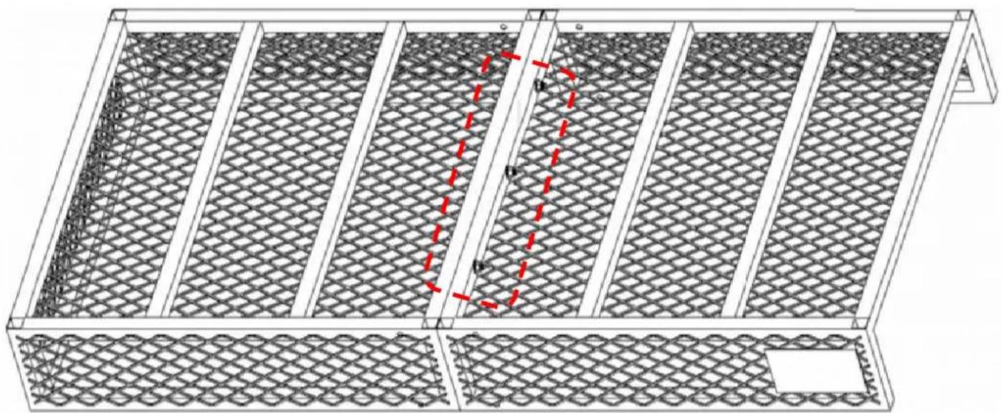
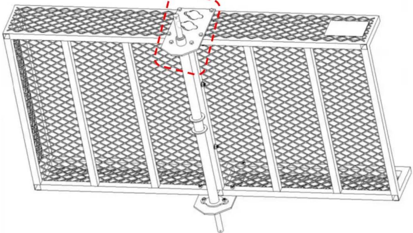
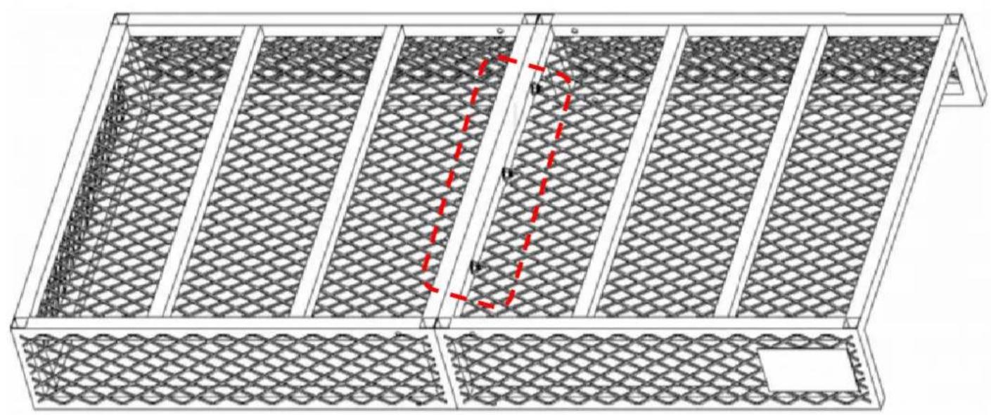
Technical diagram of a metal frame structure with lattice patterns and red dashed measurement lines (no text or symbols)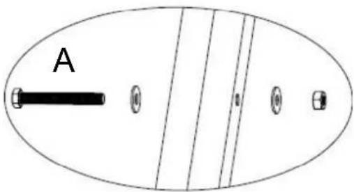
- Align Frame A(No.1) and Frame B(No.2) in the correct positions (with the cart bed fa
- When fixing the frame with screws, please note that the washers must be used in a the requirements specified in the detail drawing.
- Finally, tighten them to secure the connection.
STEP 2
natural_image
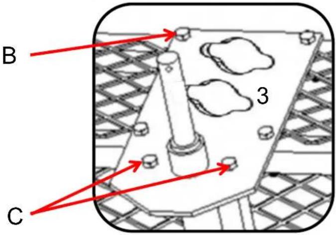
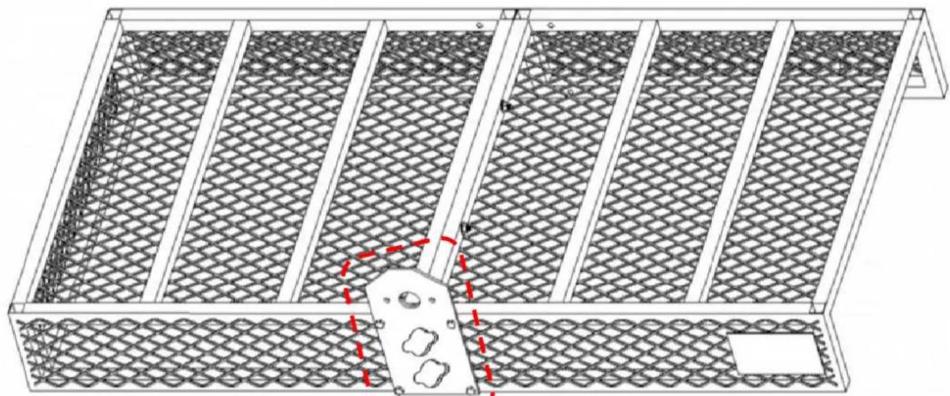
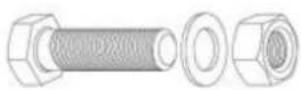
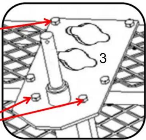
Technical line drawing of a mechanical housing or plate with two circular indentations and mounting holes (no text or symbols)3 x 1
B x4 Screw M8*45

- Install the Fixed plate(No.3) on the Frame.
- At the fixing holes, insert Screw(No.B) first. Then place washer and nut in sequence
- Finally, tighten them to secure the connection.
STEP 3
natural_image
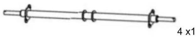
Simple line drawing of a four-pole straight rod with no text or symbols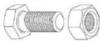
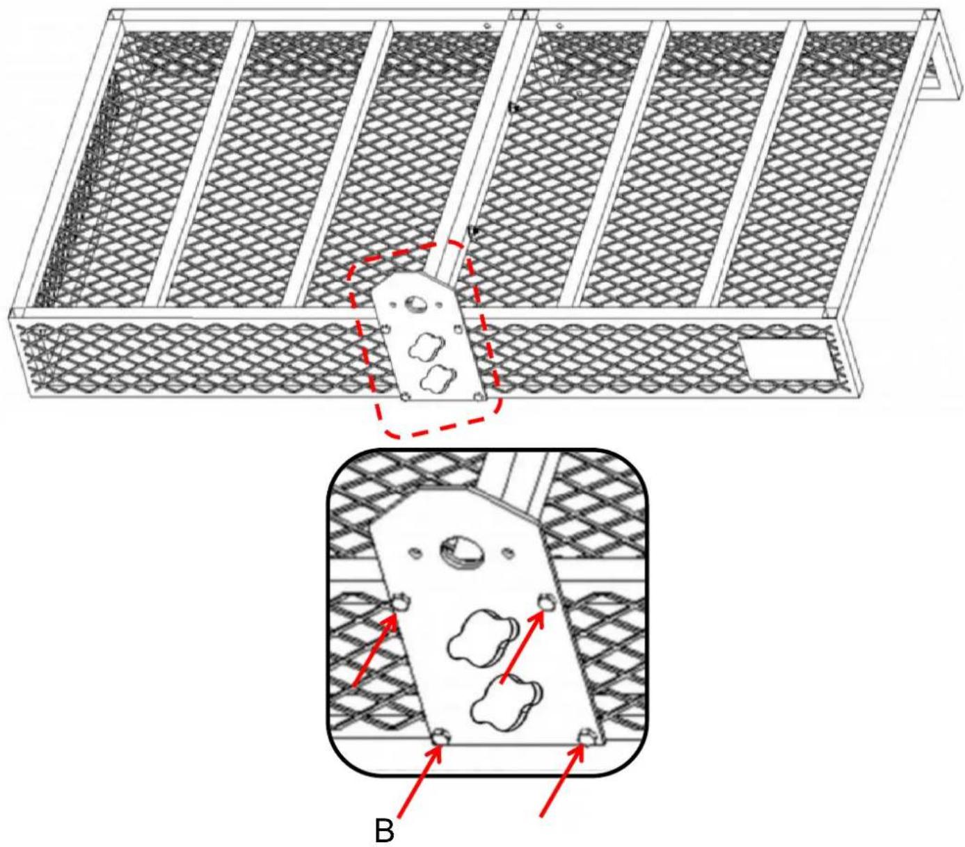
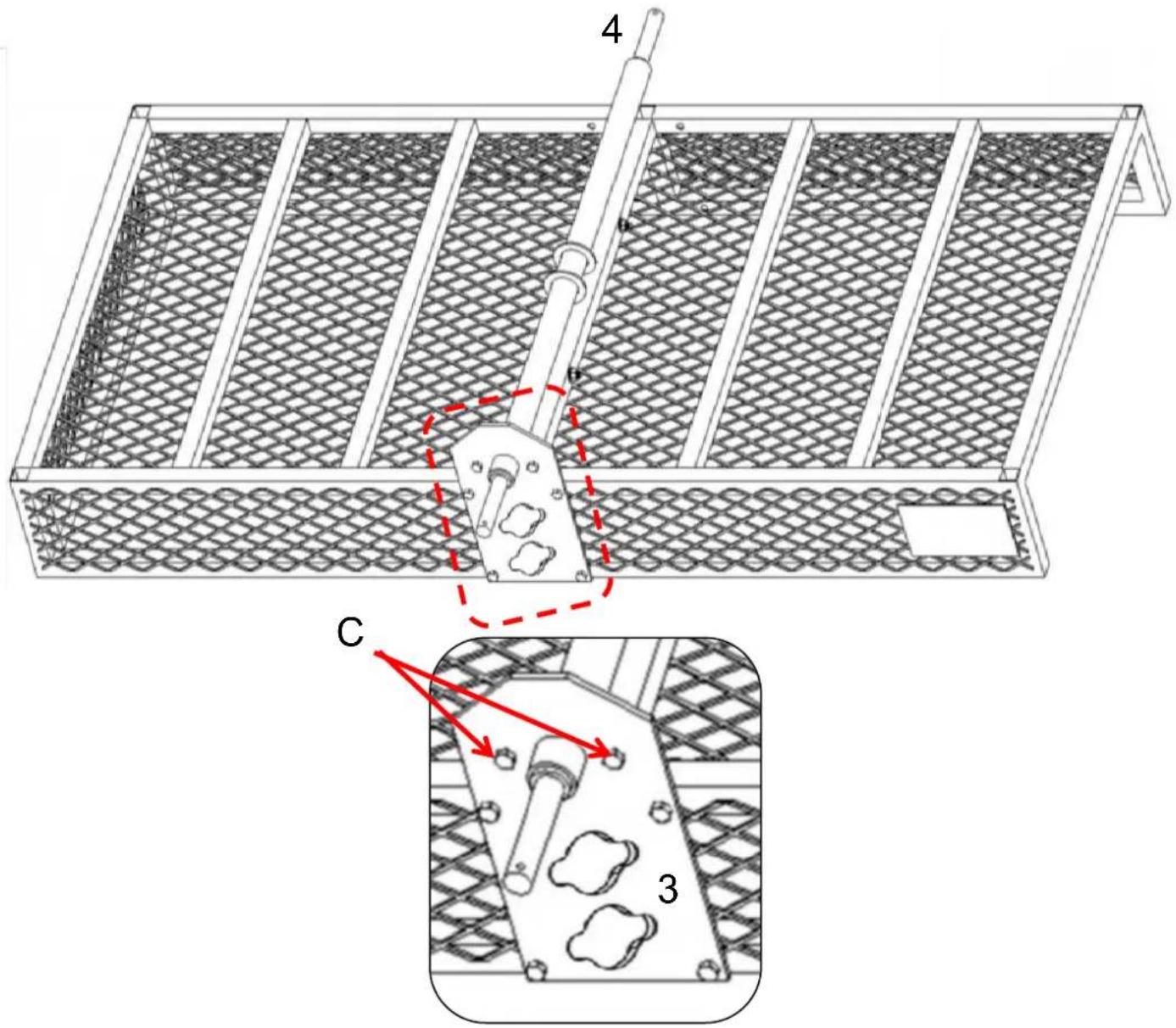
C x2 Screw M10*25
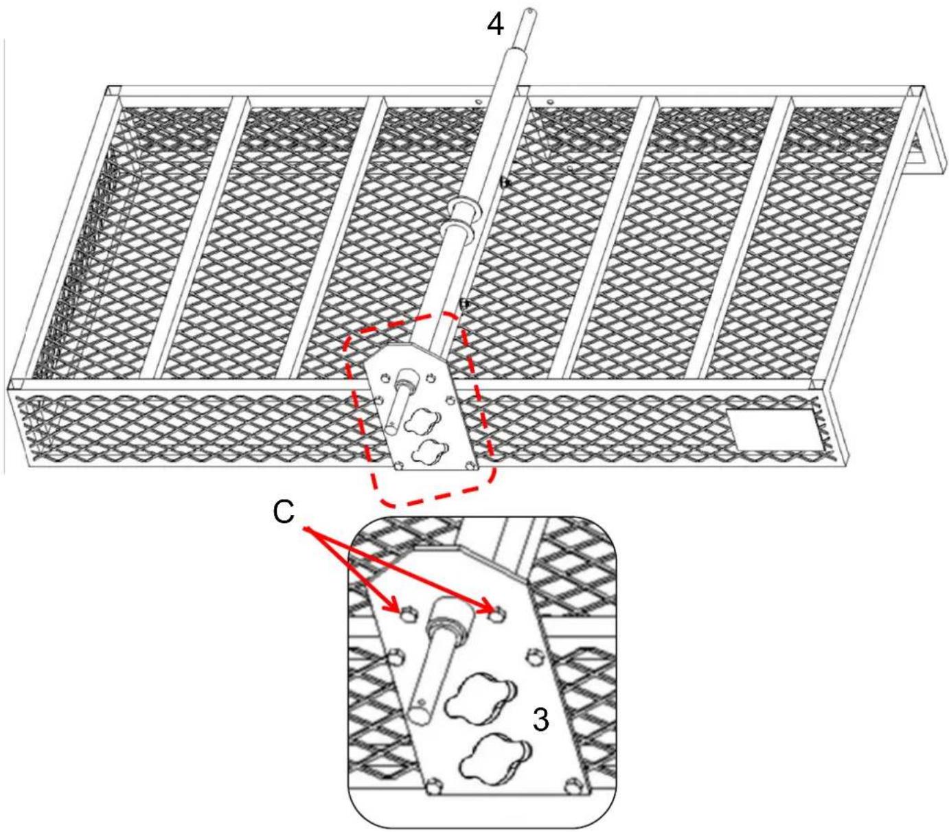
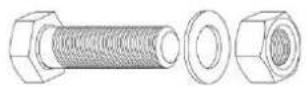
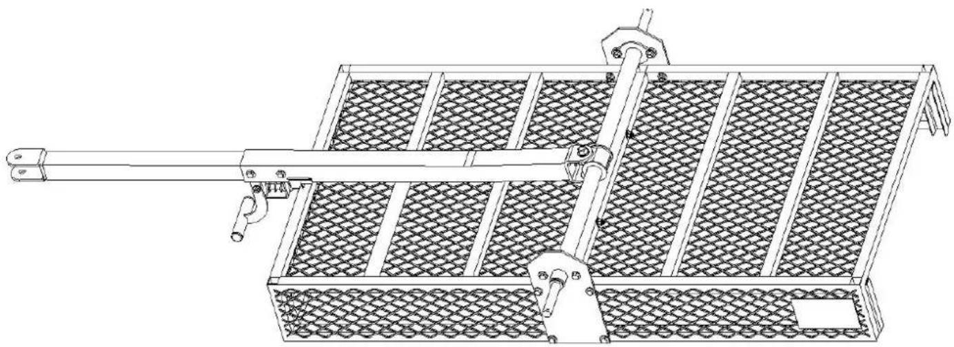
- Insert the Axle(No.4) into the holes of the Fixed plate(No.3).
- Insert Screw(No.C) into the connection holes between the Axle and the Fixed plate. T other side, place washer and nut in sequence.
- Finally, tighten them to secure the connection.
| STEP 4 | ||
 3 x1 3 x1 | 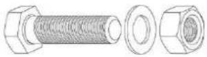 B x4Screw M8*45 B x4Screw M8*45 | 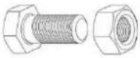 C x2 Screw M10*25 C x2 Screw M10*25 |
  1. Insert the Axle(No.4) into the holes of the Fixed plate(No.3).2. Insert Screw(No.B) and Screw(No.C) into the connection holes between the Axle and tplate. Then, on the other side, place washer and nut in sequence.3. Finally, tighten them to secure the connection. 1. Insert the Axle(No.4) into the holes of the Fixed plate(No.3).2. Insert Screw(No.B) and Screw(No.C) into the connection holes between the Axle and tplate. Then, on the other side, place washer and nut in sequence.3. Finally, tighten them to secure the connection. | ||
- Insert the Axle(No.4) into the holes of the Fixed plate(No.3).
- Insert Screw(No.B) and Screw(No.C) into the connection holes between the Axle and t plate. Then, on the other side, place washer and nut in sequence.
- Finally, tighten them to secure the connection.
| STEP 5 | ||
 Ex1 Ex1 | 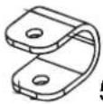 5 x1 5 x1 | 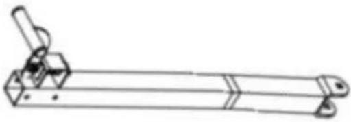 7 x1 7 x1 |
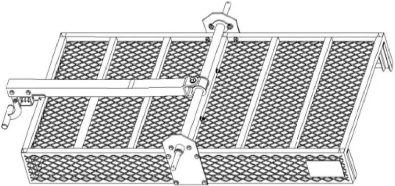  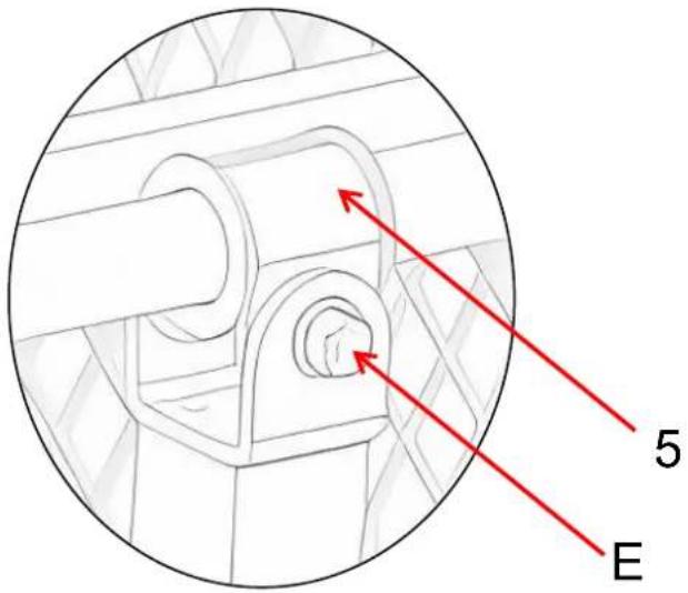 | ||
| 1. Place the U-shaped part(No.5) in the middle position of the axle(No.4).2. Align the U-shaped part(No.5) and Connecting rod B(No.7) with the installation holes.3. Insert Screw (No.E) through the holes of the two connecting rods, and then screw or | ||
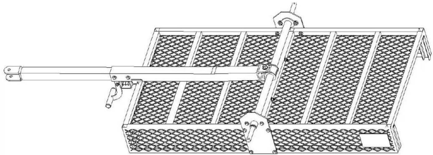
- Place the U-shaped part(No.5) in the middle position of the axle(No.4).
- Align the U-shaped part(No.5) and Connecting rod B(No.7) with the installation holes.
- Insert Screw (No.E) through the holes of the two connecting rods, and then screw or
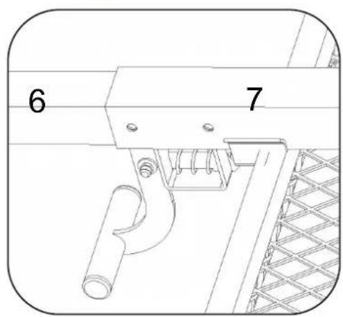
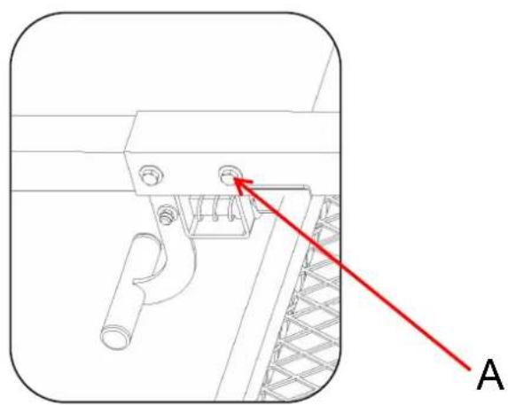
STEP 6
A x2 Screw M8*70
natural_image
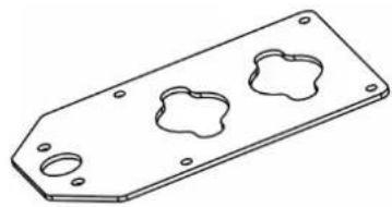
Technical line drawing of a metal bracket with two mounting holes (no text or symbols)6 x1
natural_image
Technical line drawing of a mechanical device with a horizontal rod and mesh panel (no text or symbols)STEP-1
STEP-2

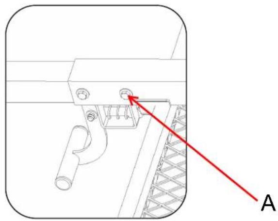
natural_image
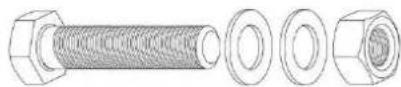
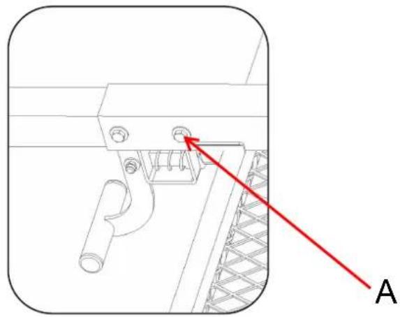
Technical line drawing of a mechanical component with a red arrow and label 'A' (no text or symbols on the diagram itself)- Insert Connecting rod A(No.6) and Connecting rod B(No.7) into each other.
- Insert Screw(No.A) and place washer into the connection holes, and then place washe sequence on the other side.
- Finally, tighten them to secure the connection.
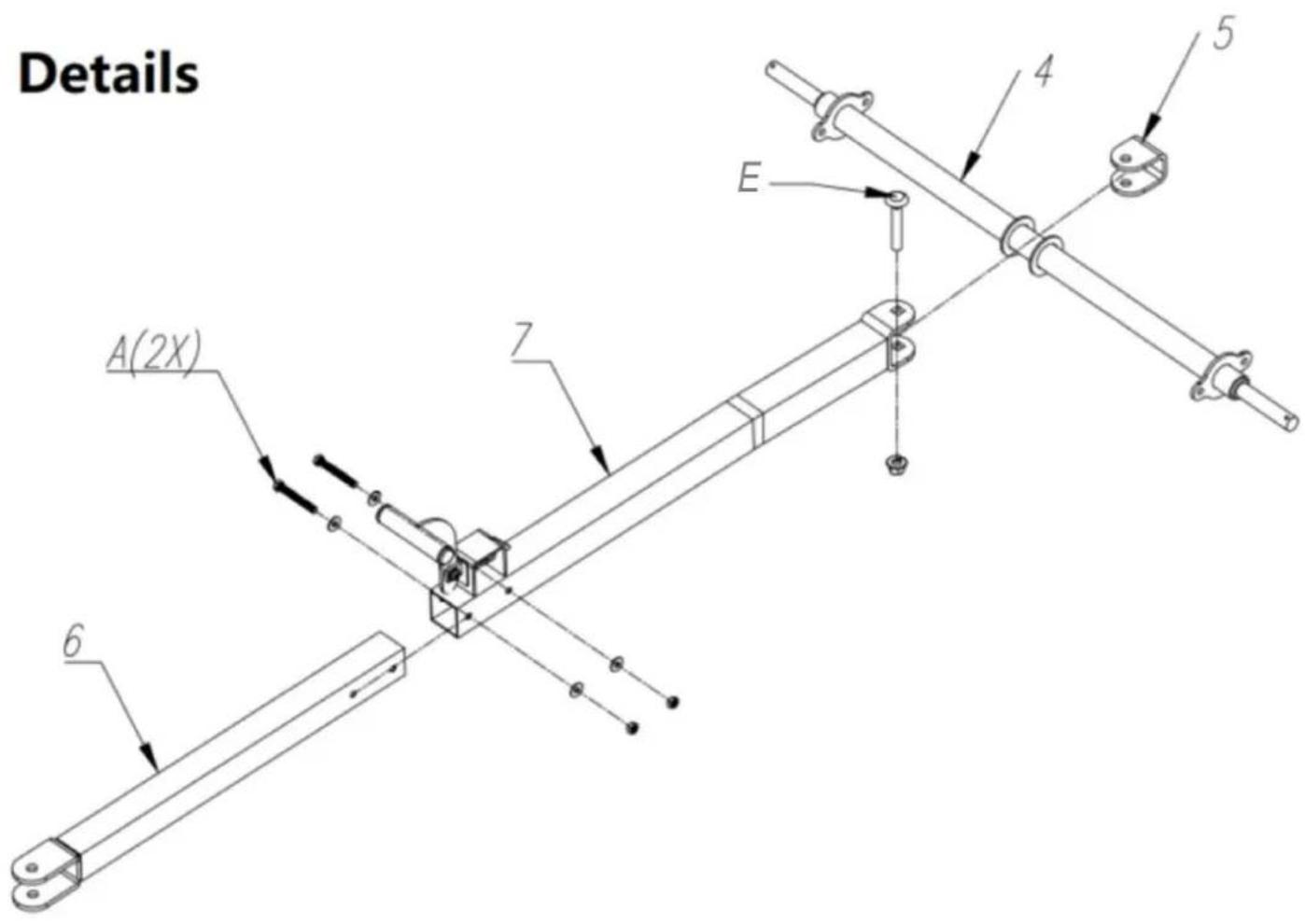
NOTE: This page shows the exploded view of parts from Step 3 to which is convenient for you to check if the installation is corre
| STEP 7 | |||
 F x2 F x2 |  D x4 D x4 |  3 x2 3 x2 | |
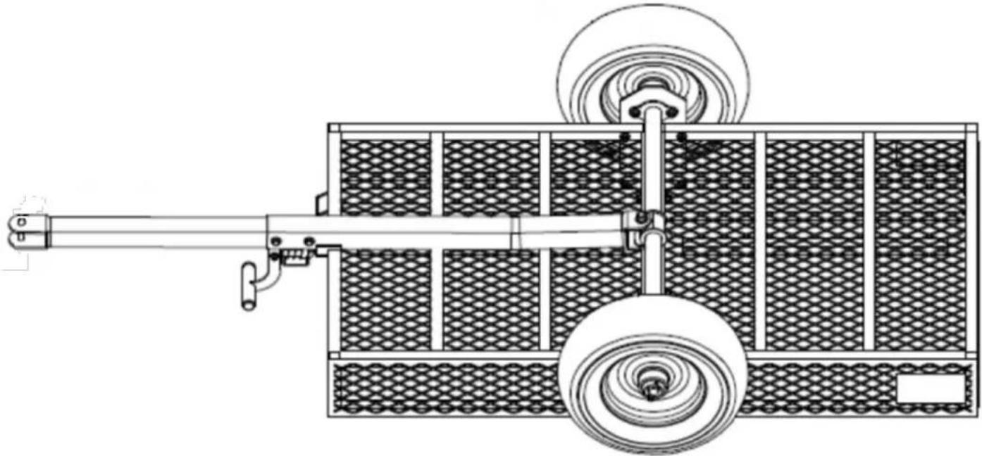 8 8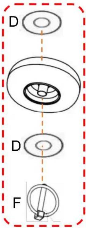 1. First, put Washer(No.D) on the mounting shaft of the Wheel, and then install the Wh designated position.2. Put Washer(No.D) on first, and then insert the O-type cotter pin(No.F) into the corresp on the mounting shaft.3. Note: The inflation port should face outwards. 1. First, put Washer(No.D) on the mounting shaft of the Wheel, and then install the Wh designated position.2. Put Washer(No.D) on first, and then insert the O-type cotter pin(No.F) into the corresp on the mounting shaft.3. Note: The inflation port should face outwards. | |||
| STEP 8 | |||
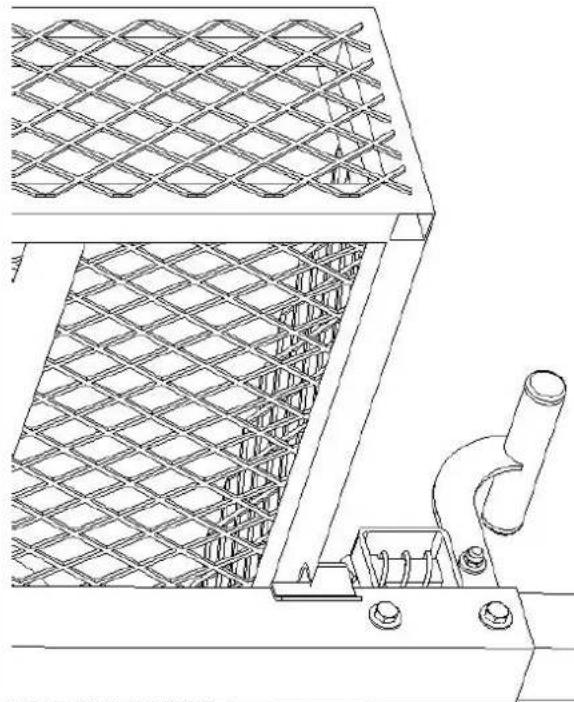
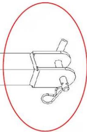
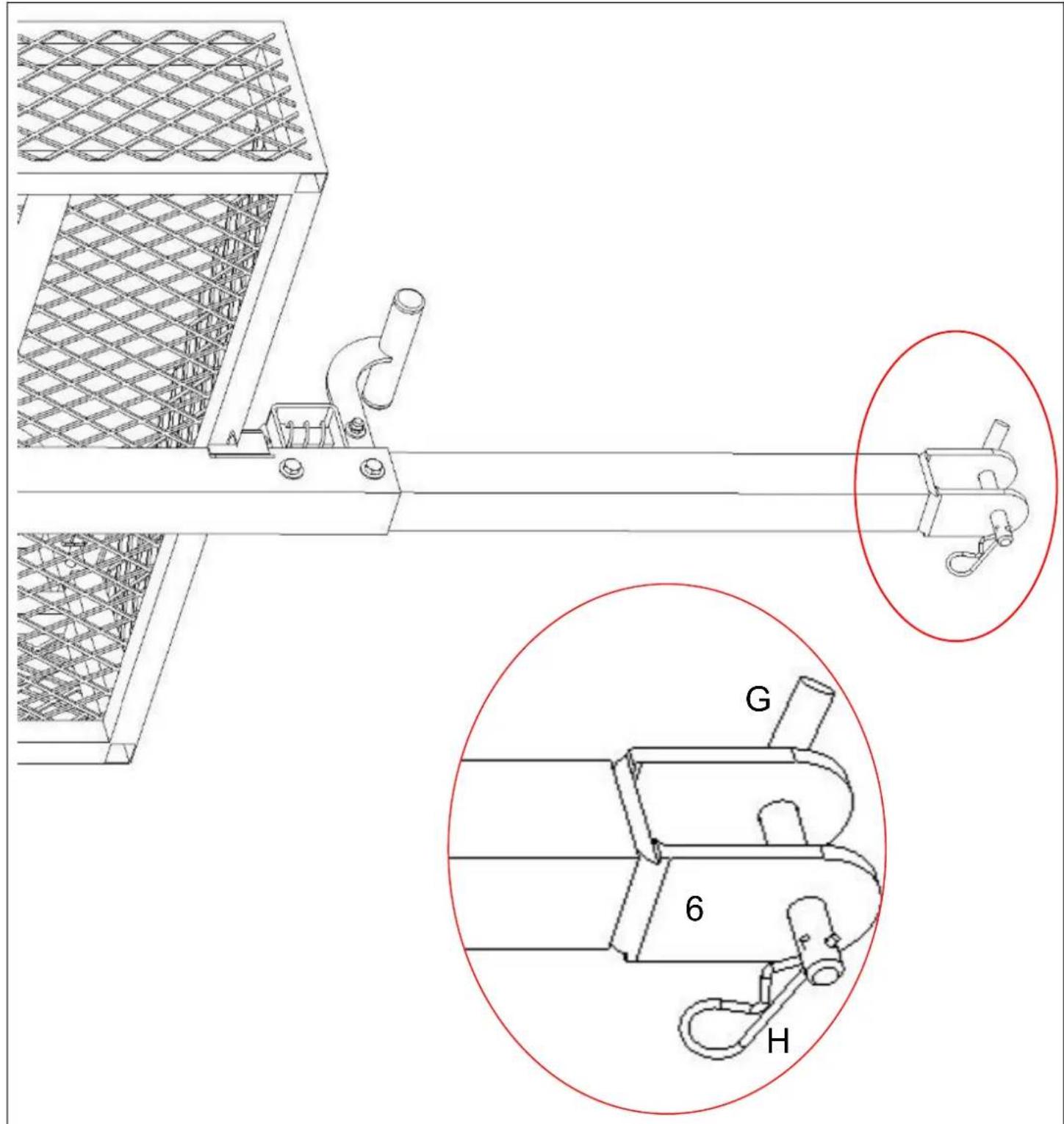
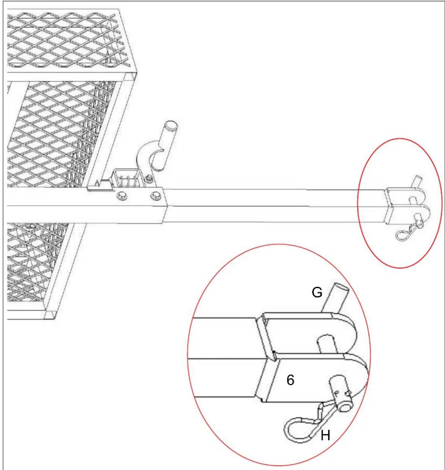
 G x1 G x1 | 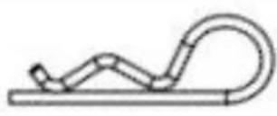 H x1 H x1 | ||
 |  | ||
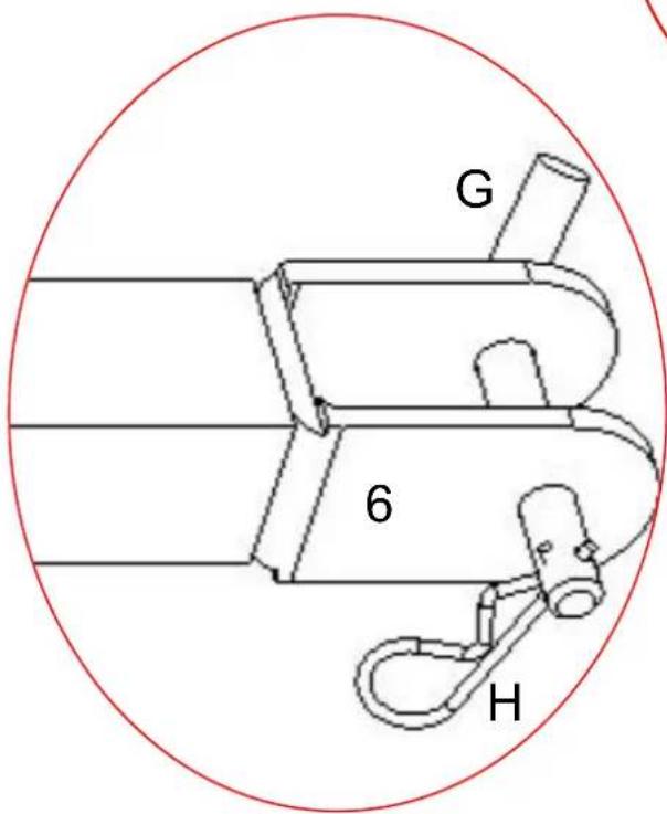 | |||
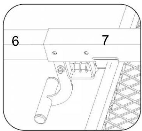
- Insert the pin(No.G) into Connecting rod A(No.6).
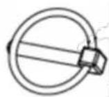
- Insert the R-type cotter pin(No.H) into the hole of the pin(No.G).
STEP 10
natural_image
Pure technical line drawing of a bent pipe or duct with no text, numbers, or symbols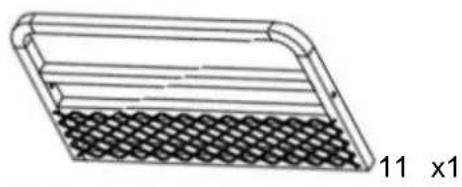
natural_image
Technical line drawing of a rectangular device with grid pattern and curved top edge (no text or symbols)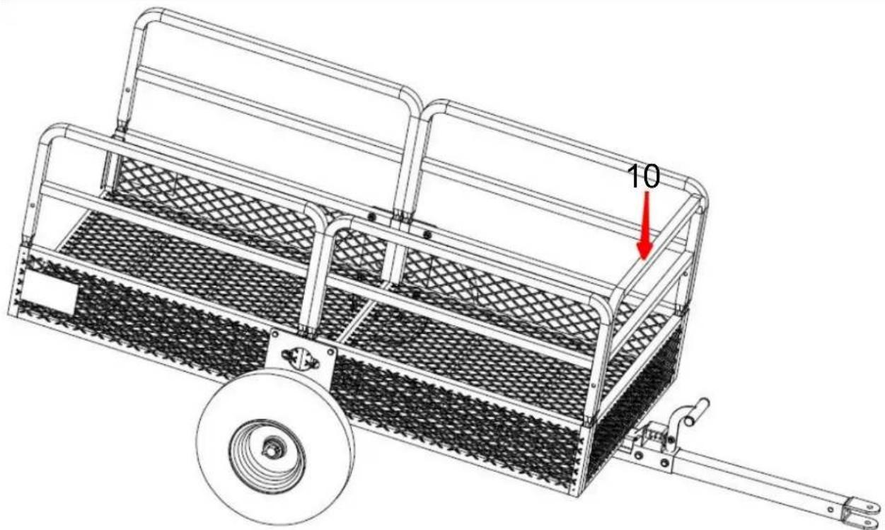
natural_image
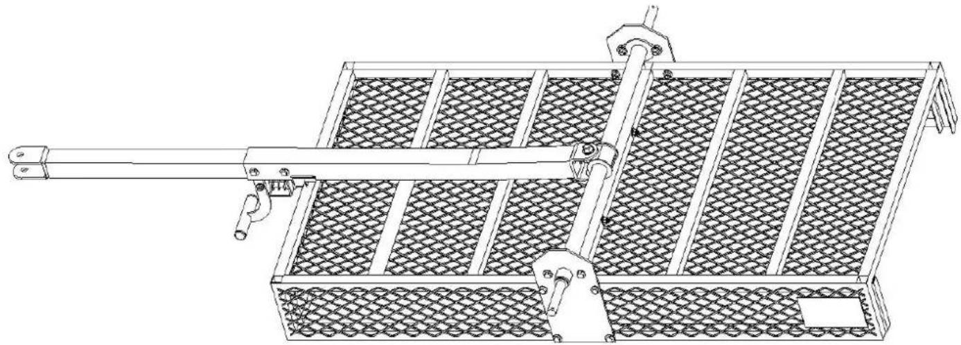
Technical line drawing of a wheeled cart with mesh pattern and a wheel, no text or symbols present
natural_image
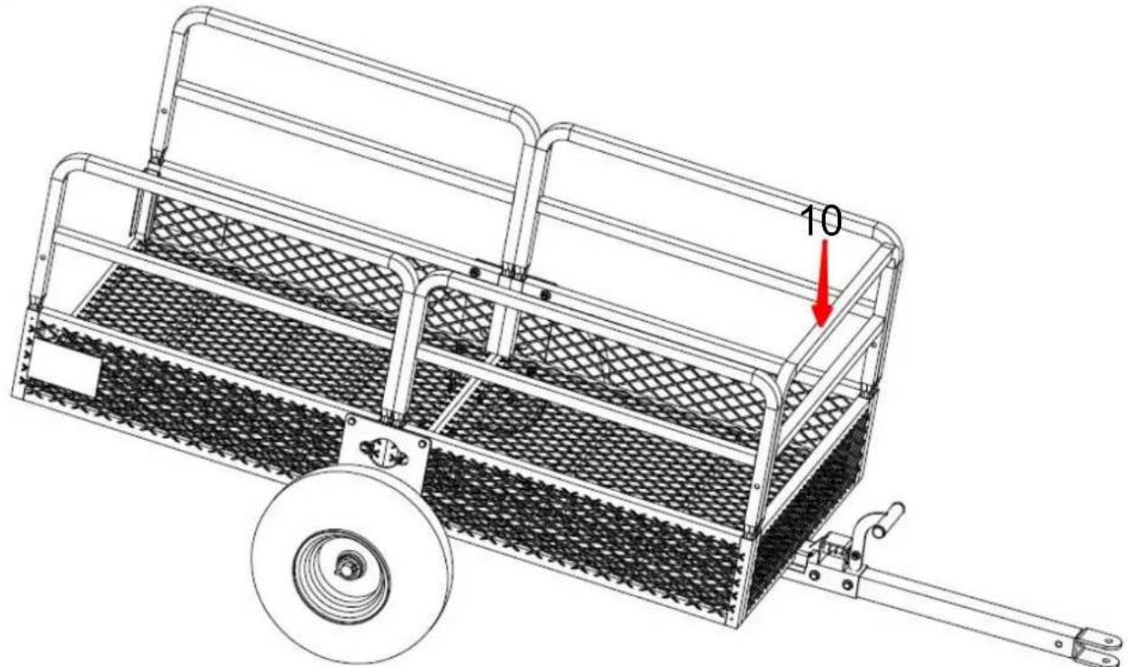
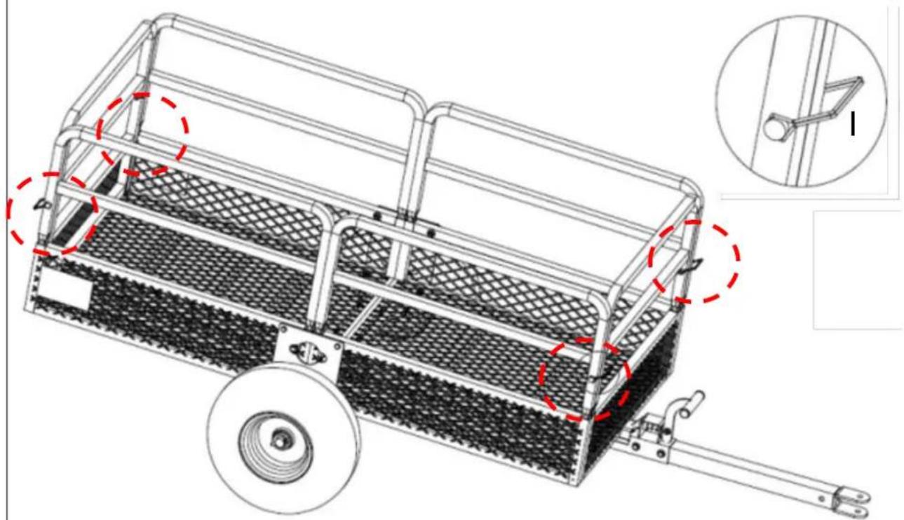
Technical line drawing of a wheeled cart with mesh pattern and a wheel, no text or symbols present- Install the Front guardrail(No.10) on the left and right sides of the frame.
- Install the Rear guardrail(No.11) on the left and right sides of the frame.
PRODUCT PARAMETER
| Model | TC4268 |
| Volume | 15 cu.ft |
| Carriage size | 1370*710*395mm / 54*28*15.5inchs |
| Maximum loading capacity | 1500 LBS |
| Model | TC4278 |
| Volume | 22 cu.ft |
| Carriage size | 1490*735*575mm / 58.6*28.9*22.6inchs |
| Maximum loading capacity | 1600 LBS |
| Model | TC4288 |
| Volume | 28 cu.ft |
| Carriage size | 1524*810*635mm / 60*32*25inchs |
| Maximum loading capacity | 1765 LBS |
Manufacturer: Shanghaimuxinmuyeyouxiangongsi
Address: Shuangchenglu 803nong11hao1602A-1609shi, baoshanqu, shanghai 200000 CN.
Imported to AUS: SIHAO PTY LTD. 1 ROKEVA STREETEASTWOOD NSW 2122 Australia
Imported to USA: Sanven Technology Ltd. Suite 250, 9166 Anaheim Place, Rancho Cucamonga, CA 91730
| UK | REP |
YH CONSULTING LIMITED. C/O YH Consultin
Limited Office 147, Centurion House, London
Road, Staines-upon-Thames, Surrey, TW18 4A>
| EC | REP |
E-CrossStu GmbH
Mainzer Landstr.69,
60329 Frankfurt am Main.

VEVOR
Affordable. Reliable. Home Improvement.
PRZYCZEPY OGRODOWE
MODELE: TC4268/TC4278/TC4288
MO DEL: TC4268/TC4278/TC4288
natural_image
Technical line drawing of a two-wheeled cart with mesh panels and a wheel (no text or symbols)
https://youtu.be/aIQyVCV19sY
ASSEMBLY STEP
KROK 1
natural_image
3D rendering of a rectangular electronic device with a mesh panel and top frame (no text or symbols visible)1 x 1

natural_image
3D diagram of a rectangular container filled with mesh patterns, no text or symbols present2x1
Śruba x3 M8*7 0

natural_image
Technical line drawing of a metal frame structure with lattice pattern and red dashed measurement lines (no text or symbols)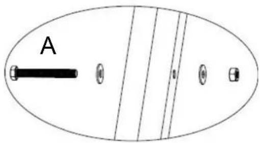
natural_image
Isometric line drawing of a rectangular metal plate with two circular indentations on both sides (no text or symbols)3 x 1
Śruba B x4 M8* 45
natural_image
Technical line drawing of a metal frame structure with lattice panels and a central mounting bracket (no text or symbols)
natural_image
Technical diagram of a mechanical component with red arrows indicating directional movement (no text or symbols)B
natural_image
Technical line drawing of a metal bracket with two mounting holes (no text or symbols)6×1
natural_image
Technical line drawing of a mechanical device with a horizontal rod and mesh panel (no text or symbols)STEP-1

STEP-2
natural_image
Technical line drawing of a mechanical assembly with a red arrow pointing to a component labeled 'A' (no text or symbols beyond label)NOTE: This page shows the exploded view of parts from Step 3 to which is convenient for you to check if the installation is corre
natural_image
Pure mechanical component diagram with no text or symbols
natural_image
Diagram of a rectangular device with horizontal lines and a mesh pattern, labeled '11 x1' (no text or symbols on the diagram itself)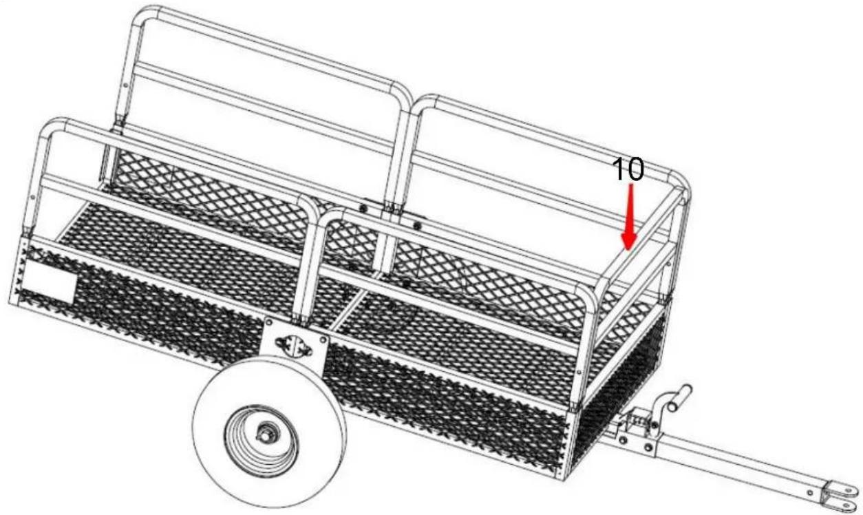
natural_image
Technical line drawing of a wheeled cart with a wheel and handle, featuring a red arrow pointing to the number 10 (no text or symbols on the cart itself)
natural_image
Technical line drawing of a wheeled cart with mesh pattern and a wheel, no text or symbols presentYH CONSULTING LIMITED. C/O YH Consultin
Limited Office 147, Centurion House, London
Road, Staines-upon-Thames, Surrey, TW18 4A>
| EC | REP |
E-CrossStu GmbH
Mainzer Landstr.69,
60329 Frankfurt am Main.

VEVOR
Affordable. Reliable. Home Improvement.
GARTENANHÄNGER
MODELL: TC4268/TC4278/TC4288
MODELL : TC4268/TC4278/TC4288

natural_image
Line drawing of a two-wheeled cart with a wheel and handle, no text or symbols present
https://youtu.be/aIQyVCV19sY
ASSEMBLY STEP
SCHRITT 1

natural_image
3D rendering of a rectangular electronic device with a mesh panel and top frame (no text or symbols visible)1 x 1
natural_image
3D diagram of a rectangular container filled with mesh patterns, no text or symbols present2x1

A x3 Schraube M8*7 0

natural_image
Technical line drawing of a metal frame structure with lattice pattern and red dashed measurement lines (no text or symbols)
natural_image
Isometric line drawing of a rectangular metal plate with two circular indentations on both sides (no text or symbols)
3 x1
natural_image
Technical line drawing of a metal frame structure with lattice pattern and mounting holes (no text or symbols)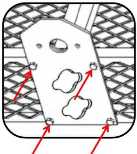
natural_image
Technical diagram of a mechanical component with red arrows indicating directional movement (no text or symbols)B
NOTE: This page shows the exploded view of parts from Step 3 to which is convenient for you to check if the installation is corre
natural_image
Pure diagram of a bent pipe or tube with no text, numbers, or symbols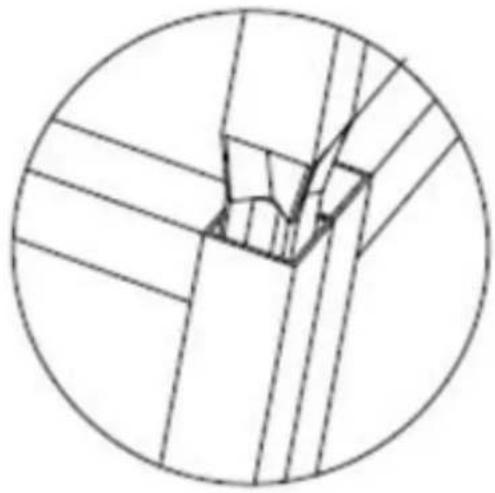
natural_image
Pure technical line drawing of a mechanical joint or bracket (no text or symbols)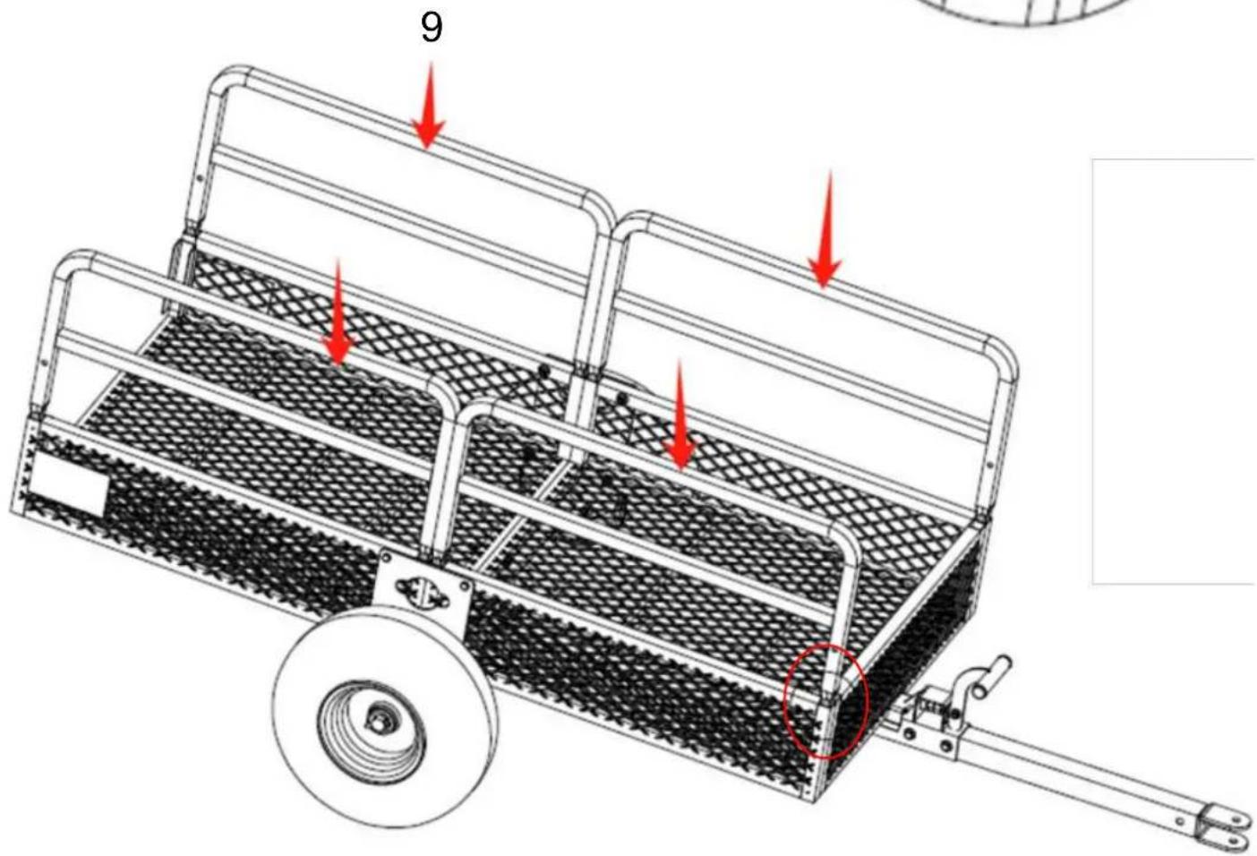
Place, Rancho Cucamonga, CA 91730
| UK | REP |
YH CONSULTING LIMITED. C/O YH Consultin
Limited Office 147, Centurion House, London
Road, Staines-upon-Thames, Surrey, TW18 4A>
| EC | REP |
E-CrossStu GmbH
Mainzer Landstr.69,
60329 Frankfurt am Main.

VEVOR
Affordable. Reliable. Home Improvement.
REMORQUES DE JARDIN
MODÈLE : TC4268/TC4278/TC4288
MODÈLE : TC4268/TC4278/TC4288

natural_image
Line drawing of a two-wheeled cart with mesh panel and wheel (no text or symbols)
https://youtu.be/aIQyVCV19sY
ASSEMBLY STEP
ÉTAPE 1

natural_image
Technical line drawing of a metal frame structure with lattice pattern and red dashed measurement lines (no text or symbols)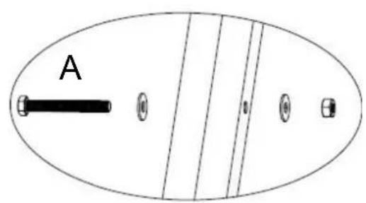
natural_image
Isometric line drawing of a rectangular metal plate with two circular indentations on both sides (no text or symbols)3 × 1

Vis B x4 M8* 45

natural_image
Technical line drawing of a metal frame structure with lattice panels and a central mounting bracket (no text or symbols)
natural_image
Technical diagram of a mechanical component with red arrows indicating directional movement (no text or symbols)B
natural_image
Technical line drawing of a metal bracket with two mounting holes (no text or symbols)6 x 1

natural_image
Technical line drawing of a mechanical assembly with a horizontal rod and meshed panel (no text or symbols)STEP-1
STEP-2
natural_image
Technical line drawing of a mechanical component with a red arrow and label 'A' (no text or symbols on the diagram itself)NOTE: This page shows the exploded view of parts from Step 3 to which is convenient for you to check if the installation is corre-
| ÉTAPE 7 | |||
 F x2 F x2 | 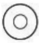 D x4 D x4 |  8 x 2 8 x 2 | |
 | |||

natural_image
Simple line drawing of a bent pipe or elbow joint (no text or symbols)G x1

H×1
natural_image
Pure diagram of a U-shaped pipe or tube with two ends and a label '9 x 4' below (no text or symbols on the pipe itself)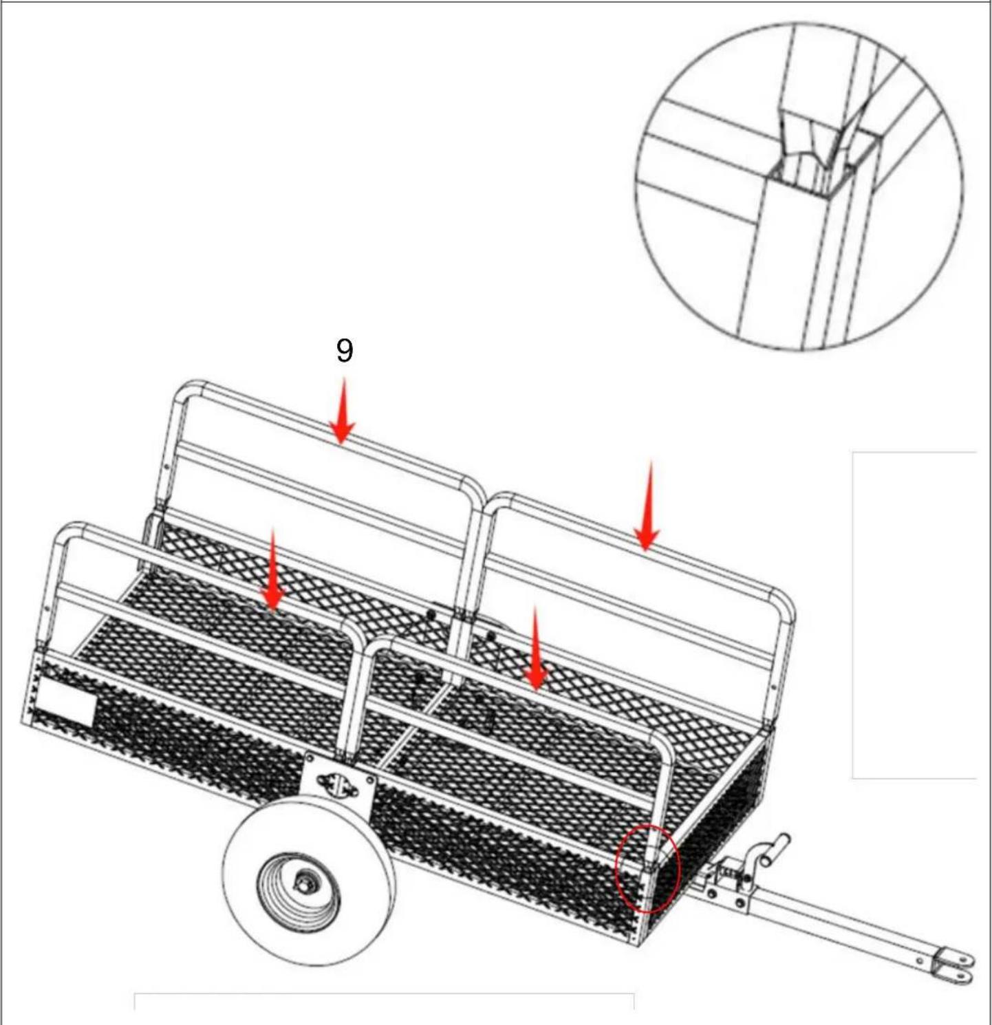
natural_image
Pure technical line drawing of a U-shaped pipe or support structure without any text, labels, or symbols10 x 1

natural_image
Technical line drawing of a rectangular component with horizontal grooves and a textured base (no text or symbols)11 x 1

natural_image
Technical line drawing of a wheeled cart with a wheel and handle, featuring a red arrow pointing to the number 10 (no text or symbols on the cart itself)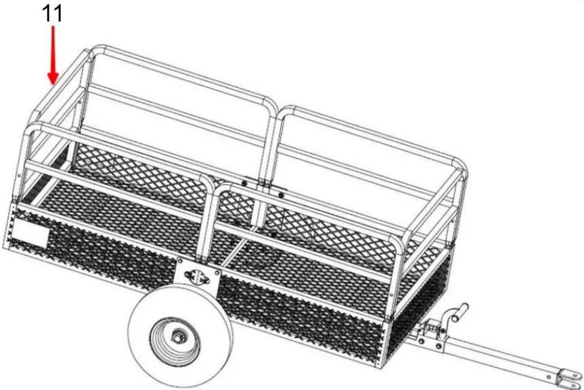
natural_image
Technical line drawing of a wheeled cart with mesh pattern and a wheel, no text or symbols presentnatural_image
Blank white rectangular shape with no text, numbers, or symbols12 x 1

natural_image
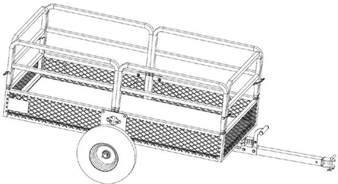
Technical line drawing of a wheeled cart with mesh pattern and wheel, showing structural details (no text or symbols)YH CONSULTING LIMITED. C/O YH Consultin
Limited Office 147, Centurion House, London
Road, Staines-upon-Thames, Surrey, TW18 4A>
| EC | REP |
E-CrossStu GmbH
Mainzer Landstr.69,
60329 Frankfurt am Main.

VEVOR
Affordable. Reliable. Home Improvement.
TUINTRAILERS
MODEL: TC4268/TC4278/TC4288
natural_image
Technical line drawing of a two-wheeled cart with mesh panels and a wheel (no text or symbols)
https://youtu.be/aIQyVCV19sY
ASSEMBLY STEP
STAP 1
natural_image
3D rendering of a grid-patterned rectangular device with a label on the front panel (no text or symbols visible)1x1

natural_image
3D diagram of a rectangular container filled with mesh patterns, no text or symbols present2x1
natural_image
Technical line drawing of a metal frame structure with lattice pattern and red dashed measurement lines (no text or symbols)
natural_image
Isometric line drawing of a rectangular metal plate with two circular indentations on both sides (no text or symbols)3x1
B x4 Schroef M8* 45
natural_image
Simple line drawing of a cylindrical object with three curved ends, resembling a wire or rod (no text or symbols)4x1

C x2 Schroef M10* 25
NOTE: This page shows the exploded view of parts from Step 3 to which is convenient for you to check if the installation is corre
natural_image
Pure technical line drawing of a bent pipe or support structure without any text, numbers, or symbols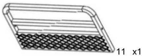
natural_image
Diagram of a rectangular container with a mesh pattern and a side label '11 x1' (no text or symbols on the diagram itself)
natural_image
Technical line drawing of a two-wheeled cart with a wheel and handle, featuring a red arrow pointing to the number 10 (no text or symbols on the cart itself)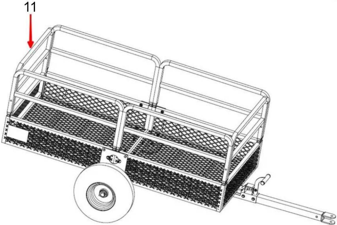
natural_image
Technical line drawing of a wheeled cart with mesh pattern and a wheel, no text or symbols presentYH CONSULTING LIMITED. C/O YH Consultin
Limited Office 147, Centurion House, London
Road, Staines-upon-Thames, Surrey, TW18 4A>
| EC | REP |
E-CrossStu GmbH
Mainzer Landstr.69,
60329 Frankfurt am Main.

VEVOR
Affordable. Reliable. Home Improvement.
TRÄDGÅRDSVAGNAR
MODELL: TC4268/TC4278/TC4288
MODELL : TC4268/TC4278/TC4288

natural_image
Line drawing of a two-wheeled cart with mesh panel and wheel (no text or symbols)
https://youtu.be/aIQyVCV19sY
ASSEMBLY STEP
STEG 1
natural_image
3D rendering of a rectangular metal tray with a mesh pattern on top (no text or symbols)1 x 1
natural_image
3D diagram of a rectangular container filled with mesh patterns, no text or symbols present2x1

A x3 Skruv M8*7 0
natural_image
Technical line drawing of a structural frame with lattice pattern and red dashed lines indicating hidden edges (no text or symbols)
natural_image
Isometric line drawing of a rectangular metal plate with two circular indentations on both sides (no text or symbols)3 x 1

B x4 Skruv M8* 45

natural_image
Simple line drawing of a cylindrical object with three curved ends, resembling a wire or rod (no text or symbols)4x1
C x2 Skruv M10* 25
natural_image
Isometric line drawing of a rectangular metal plate with two circular indentations and mounting holes (no text or symbols)3 x 1
B x4 Skruva M8* 45
C x2 Skruv M10* 25
B
C
natural_image
Technical line drawing of a structural frame with mesh pattern and vertical supports (no text or symbols)natural_image
Technical line drawing of a metal bracket with two mounting holes (no text or symbols)6x1
natural_image
Technical line drawing of a mechanical assembly with a horizontal rod and meshed panel (no text or symbols)STEP-1
STEP-2

natural_image
Technical line drawing of a mechanical component with a red arrow pointing to a section labeled 'A' (no text or symbols beyond label)NOTE: This page shows the exploded view of parts from Step 3 to which is convenient for you to check if the installation is corre
natural_image
Pure technical line drawing of a bent pipe or support structure without any text, numbers, or symbols10 x 1
natural_image
Technical line drawing of a rectangular component with internal layered structure and mesh texture (no text or symbols)11 x 1

natural_image
Technical line drawing of a two-wheeled cart with a wheel and handle, featuring a red arrow pointing to the number 10 (no text or symbols on the cart itself)
natural_image
Technical line drawing of a wheeled cart with mesh pattern and a wheel, no text or symbols presentYH CONSULTING LIMITED. C/O YH Consultin
Limited Office 147, Centurion House, London
Road, Staines-upon-Thames, Surrey, TW18 4A>
| EC | REP |
E-CrossStu GmbH
Mainzer Landstr.69,
60329 Frankfurt am Main.

VEVOR
Affordable. Reliable. Home Improvement.
REMOLQUES DE JARDÍN
MODELO: TC4268/TC4278/TC4288
MODELO : TC4268/TC4278/TC4288

natural_image
Technical line drawing of a two-wheeled cart with mesh panels and a wheel (no text or symbols)
https://youtu.be/aIQyVCV19sY
ASSEMBLY STEP
PASO 1
natural_image
Technical line drawing of a metal-framed structural panel with lattice pattern and red dashed measurement lines (no text or symbols)
natural_image
Isometric line drawing of a rectangular metal plate with two circular indentations on both sides (no text or symbols)3x1

Tornillo B x4 M8* 45

natural_image
Technical line drawing of a metal frame structure with lattice panels and a central mounting bracket (no text or symbols)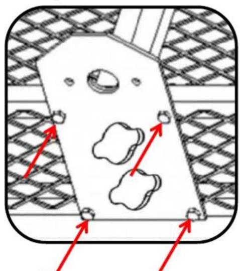
natural_image
Technical diagram of a mechanical component with red arrows indicating directional movement (no text or symbols)B
natural_image
Technical line drawing of a metal bracket with two mounting holes (no text or symbols)6x1

natural_image
Technical line drawing of a mechanical device with a horizontal rod and mesh panel (no text or symbols)STEP-1

STEP-2
natural_image
Technical line drawing of a mechanical component with a red arrow and label 'A' pointing to a specific part (no text or symbols beyond labels)NOTE: This page shows the exploded view of parts from Step 3 to which is convenient for you to check if the installation is corre
| PASO 7 | ||
 F x2 F x2 | 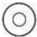 D x4 D x4 | 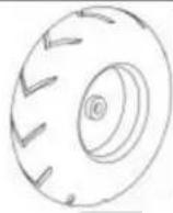 8 x 2 8 x 2 |
 | ||
natural_image
Simple line drawing of a bent pipe or elbow joint (no text or symbols)G x1
Alto x1
natural_image
Pure technical line drawing of a U-shaped pipe or support structure without any text, labels, or symbols9 x 4

natural_image
Pure technical line drawing of a U-shaped pipe or support structure without any text, labels, or symbols10 x 1

natural_image
Technical line drawing of a rectangular component with horizontal grooves and a textured base (no text or symbols)11 x 1
natural_image
Technical line drawing of a wheeled cart with a wheel and handle, featuring a red arrow pointing to the number 10 (no text or symbols on the cart itself)
natural_image
Technical line drawing of a wheeled cart with mesh pattern and a wheel, no text or symbols presentnatural_image
Blank white rectangular shape with no text, numbers, or symbols12 x 1
natural_image
Technical line drawing of a wheeled cart with mesh pattern and wheel, showing structural details (no text or symbols)YH CONSULTING LIMITED. C/O YH Consultin
Limited Office 147, Centurion House, London
Road, Staines-upon-Thames, Surrey, TW18 4A>
| EC | REP |
E-CrossStu GmbH
Mainzer Landstr.69,
60329 Frankfurt am Main.