CNE-K26F1KW - Electric motor Vevor - Free user manual and instructions
Find the device manual for free CNE-K26F1KW Vevor in PDF.

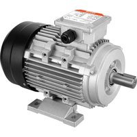
| Product Type | Electric Bicycle Motor |
| Brand | Vevor |
| Model | CNE-K26F1KW |
| Outer Diameter | 660 mm |
| Hub Diameter | 242 mm |
| Hub Length | 173 mm |
| Front Fork Distance | 100 mm |
| Rim Width | 25 mm |
| Motor Rotation Speed | 480 ± 20 rpm |
| Hub Tightening Torque | 50 N·M |
| Notch Width | 10 mm |
| Spoke Length and Screw Type | 159 mm; 12 G |
| Recommended Tire Size | 2.0 inches (5.1 cm) |
| Maximum Climbing Angle | 12° |
| Compatible Battery | 48 V (17–20 Ah) |
| Controller Rated Voltage | 48 V |
| Controller Rated Power | 1,000 W |
| Controller Maximum Current | 26 A |
| Weight Capacity | 165 lb (75 kg) |
| Compatible Frame Size | 26 inches |
| Brake Style | D/V General |
| Main Functions | Pedal Assist (PAS), throttle, cruise control, walk mode, LCD display with battery indicator and odometer |
| Package Contents | Drive wheel, controller, display, throttle, brake levers, PAS sensor, installation kit, manual |
| Maintenance and Cleaning | Clean with a dry cloth, regularly check fasteners and overall condition |
| Safety | Wear a helmet, check brakes before each ride, do not disassemble the product, keep out of reach of children |
| Repairability | Spare parts available through customer service, repair by qualified professional |
Frequently Asked Questions - CNE-K26F1KW Vevor
User questions about CNE-K26F1KW Vevor
0 question about this device. Answer the ones you know or ask your own.
Ask a new question about this device
Download the instructions for your Electric motor in PDF format for free! Find your manual CNE-K26F1KW - Vevor and take your electronic device back in hand. On this page are published all the documents necessary for the use of your device. CNE-K26F1KW by Vevor.
USER MANUAL CNE-K26F1KW Vevor
Technical Support and E-Warranty Certificate www.vevor.com/support
Electric Bike Motor
Model: CNE-K26F1KW
We continue to be committed to provide you tools with competitive price. "Save Half", "Half Price" or any other similar expressions used by us only represent estimate of savings you might benefit from buying certain tools with us compared top brands and does not necessarily mean to cover all categories of tools offered are kindly reminded to verify carefully when you are placing an order with us actually saving half in comparison with the top major brands.
MODEL: CNE-K26F1KW
natural_image
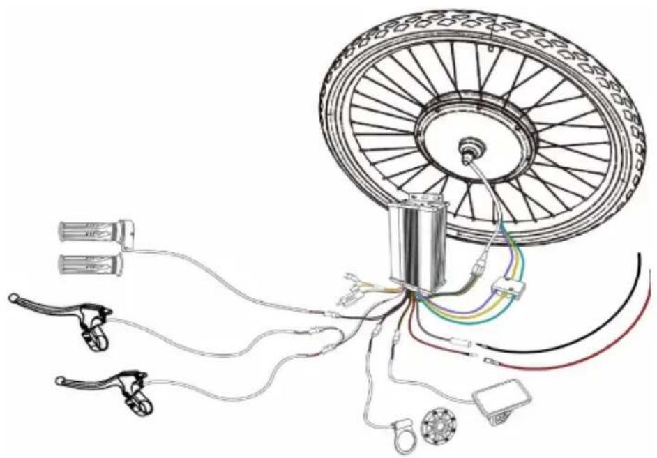
Diagram of bicycle wheel wiring and accessories (no text or symbols)NEED HELP? CONTACT US!
Have product questions? Need technical support? Please feel fr contact us:
Technical Support and E-Warranty Certificate www.vevor.com/support
This is the original instruction, please read all manual instruction carefully before operating. VEVOR reserves a clear interpretation user manual. The appearance of the product shall be subject to product you received. Please forgive us that we won't inform your data on our product.
Note:
- For safety reasons, it is most important that you read this User Manual BE you operate the bike. Improper handling can reduce its riding performance an most importantly, pose danger to your safety and health!
- The user assumes all risk of personal injuries, damage, or failure of the b or system and all other losses or damages to themselves and others and to property arising out of or as a result of improperly using the bicycle.
- This manual is not intended as a detailed user, service, repair or maintenance manual. Please seek assistance from a qualified technician for service, repairs, maintenance.

Safety Instructions
-
The user must wear helmet and other safety gears before riding for safety concerns. Ensure your helmet meets the latest certification standards and is appropriate for the type of riding you do.
-
The installation of this product must be carried by professionals with legal license and corresponding qualification.
-
If you need to modify the parts of the product, please consult our custom service in advance for feasibility.
-
We highly recommend you to level up the braking system of your bike, (brake) for safety concern.
-
Always pull the brakes and hold the handlebar firm and straight before ta off in order to make sure you keep control of the bike when power assistar
-
Always keep the controller away from water and other liquid. Should there incidence of contact with water or any other liquid, make sure to stop using product and have it inspected by professionals with legal license and corresponding qualification.
-
Never try to disassemble the parts of this product as it might cause elec shock, malfunction and serious injury
-
The product should only be cleaned with a dry cloth. Never use a wet cloth or any other liquid.
-
As with all mechanical components, this product is subjected to wear and stresses. Different materials and components may react to wear or stress fatig
in different ways. If the design life of a component has been exceeded, it is suddenly fail, possibly causing injuries to the rider. Any form of crack, scratch change of coloring in highly stressed areas indicate the life of the component been reached and must be replaced.
-
If you have an impairment or disability such as visual impairment, hearing impairment, physical impairment, cognitive/language impairment, and/or a seizure disorder, consult your physician before riding our bikes.
-
Because it is impossible to anticipate every situation or condition which occur while riding, this Manual makes no representation about the safe use of product under all conditions. There are risks associated with the use of any which cannot be predicted or avoided, and which may be caused and/or prevent through the actions of the rider, and which are the sole responsibility of the
-
When operating your bike, it is critical that you know how to properly ca each part or your bike as well as your bike as a whole. Please ensure you familiarized yourself with all aspects of your bike functions and operations bef riding it - ESPECIALLY on the open road with other traffic.
-
NEVER operate your bicycle when you are under the influence of alcohol drugs including prescribed or over the counter medications.
-
Always Ride at a speed appropriate for the conditions. High speed means higher risk. It is your responsibility to familiarize yourself and comply with the applicable within the country, state, county, province and/or city where you wi riding.
-
This product is designed to be ridden on paved roads or surfaces only. designed to with stand off-road conditions or uneven terrain. We assume no liability for any accident, injuries, or property damage incurred as a result of rider's misuse of EBC bicycles, including any damages resulting from or arising out of off-road usage.
-
Riders who do jumping, stunts, wheelies, and bike tricks should never be this product and can cause harm to themselves and others and putting undu unintended or unnecessary stress on the bike parts, frame, brakes handlebars, ste or forks can cause the components and/or the product to fail, causing serious or death. DO NOT USE THIS PRODUCT FOR JUMPING over curbs, riding a mountainous or off-road trails, or any use other than for commuting and cruise a relaxed, safe manner.
-
Never exceed the weight capacity of this product.
- Be careful to keep your body parts and other objects away from the sh teeth of the chain rings, the moving chain, the turning pedals and the crank, the spinning wheels of your bicycle.
- Check the condition of your bike before every ride. Make sure no nuts, fixings are loose, and pay particular attention to the axle, nuts and handlebar. Check the brakes for proper operation.
- Some part accessories may present a choking hazard and other hazard in children. Keep the part accessories, tools away from small children.
- It is important to your safety, performance and enjoyment to understand I things work on your bike and you have your dealer check your work before ride the bike If you have even the slightest doubt as to whether you unders something in this section of the Manual, talk to your dealer or qualified mechanic-or do not ride your bike!
- Make sure no straps are dangling where they could get caught in the w-No bags, boxes or any items should be placed in a position where they cc caught in the spokes. Double check your load for security and stability. Check see that your wheel is securely fastened and that no components or frame members are cracked or broken (in general,if at any time you notice a crack bend in your bike, stem forks, or bars of your bicycle, stop riding immediately your bike to your local bike shop and have them inspect it).
- If there is any sign of damage on the circuit wires of the product, never repairing it yourself. Please contact our customer service for more information.
- If there is a need to modify the product, please let the professionals with qualification do it for you. Please note that this product could only be used bicycle. It is not recommended to use it with tricycle, tractor and other vehic there indeed is a need to use this product with tricycle, please let the profe with qualification do it for you and ensure that the frame of tricycle is comp with the product. Also ensure the weight limit and the maximum climbing and considered.
Specifications
| Model | CNE-K26F1KW |
| Hub Length | 173 mm |
| Front Fork Distance | 100 mm |
| Outer Diameter | 660 mm |
| Rim Width | 25 mm |
| Hub Diameter | 242 mm |
| Hub Torque | 50N.M |
| Motor Rotate Speed | 480±20RPM |
| Notch Width | 10mm |
| Spoke Length &Screw Type | 159mm;12G |
| Recommended Size of Tire | 2.0"(5.1cm) |
| Maximum Climbing Angle | 12° |
| Compatible Battery | 48V(17-20AH) Almost 40KM Trip Leng |
| Braking Style | D/V General |
| Rated Voltage and Power of t Controller | 48V;1000W |
| Compatible Frame Size | 26" |
| Maximum Current of Controller | 26A |
| Weight Capacity | 165lbs(75kg) |
*Range depends on user weight, road condition, tires condition, condition of tl battery, speed and type of driving.
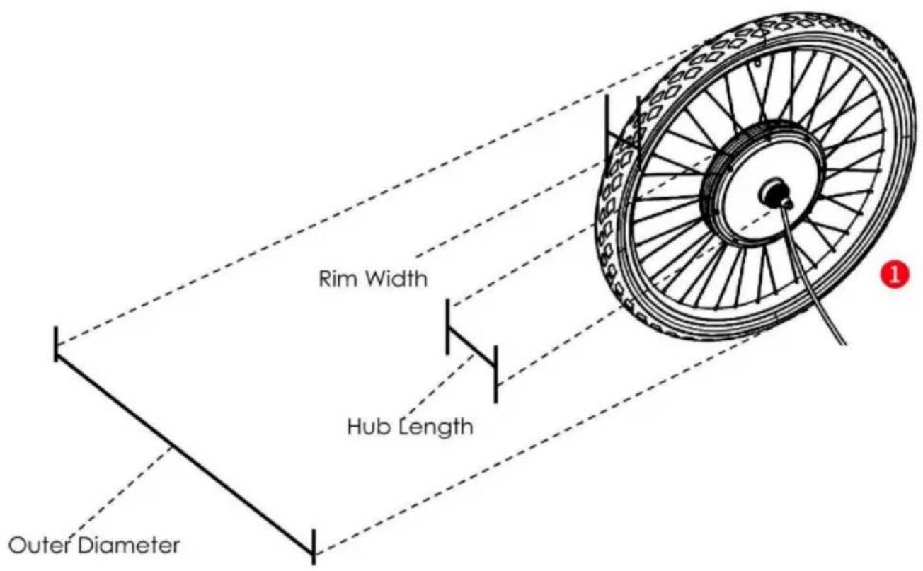
Specification Diagram

natural_image
Technical line drawing of a mechanical component with no visible text or symbols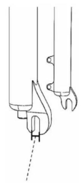
natural_image
Technical line drawing of a mechanical component with no visible text or symbolsFront Fork Distance Notch Width

Note: The diagram is for reference only. The specification data is tire-includ
Package Contents
natural_image
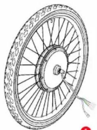
Technical line drawing of a bicycle wheel with spokes and a central hub (no text or symbols)Front motor Wheel×1
natural_image
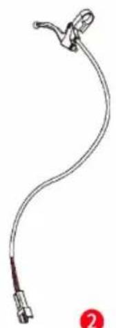
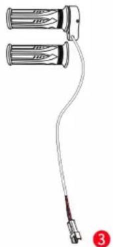
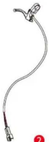
Line drawing of a medical or laboratory device with a curved, looped structure and connector (no text or symbols)Brake Lever×2
natural_image
Diagram of a cable with two cylindrical batteries connected to a terminal connector (no text or symbols)Handlebar×1 pair
natural_image
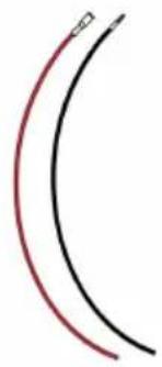
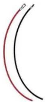
Two curved lines, one red and one black, with no text or symbols4
Power Cable×2
natural_image
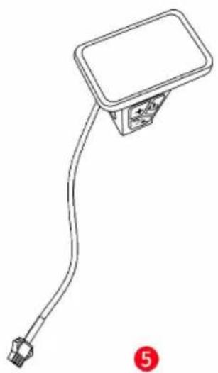
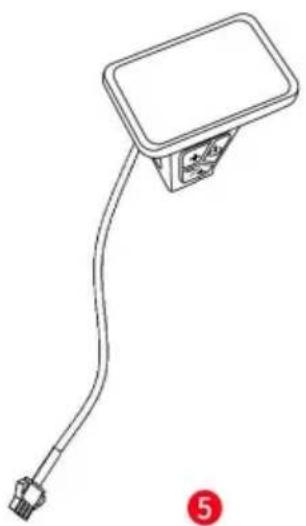
Line drawing of a flexible cable or connector with a rectangular housing and connector pin (no text or symbols)Display×1
natural_image
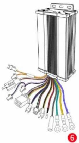
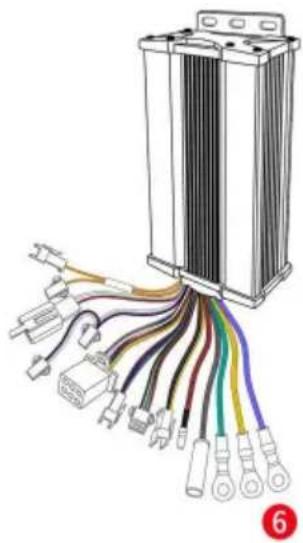
Diagram of a battery pack connected to various colored wires (no text or labels visible)Controller×1
natural_image
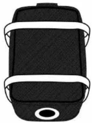
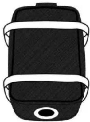
Top-down view of a black rectangular device with white straps and a circular button (no text or symbols)7
Controller Bag×1
natural_image
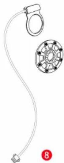
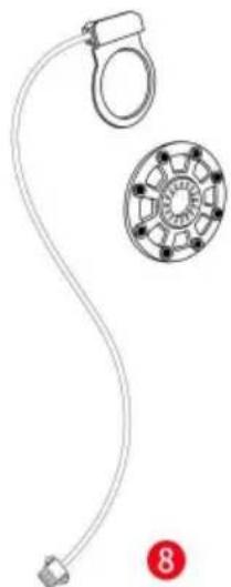
Diagram of a mechanical device with a ring and a circular component, labeled with number 8 (no text or symbols on the diagram itself)1
natural_image
Simple diagonal line drawing with no text, numbers, or symbolsWinding Pipe×1
10
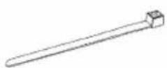
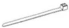
Wire Tie×1 set
11
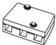
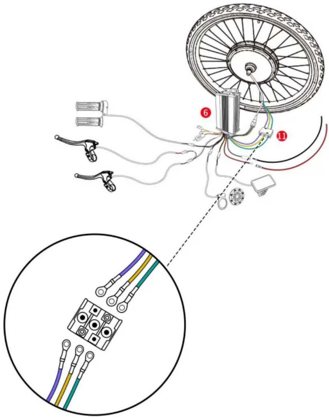
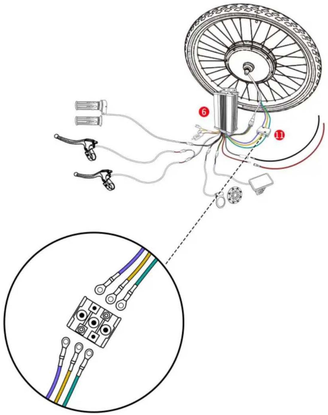
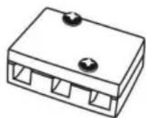
Junction Box×1
Assembly Instructions
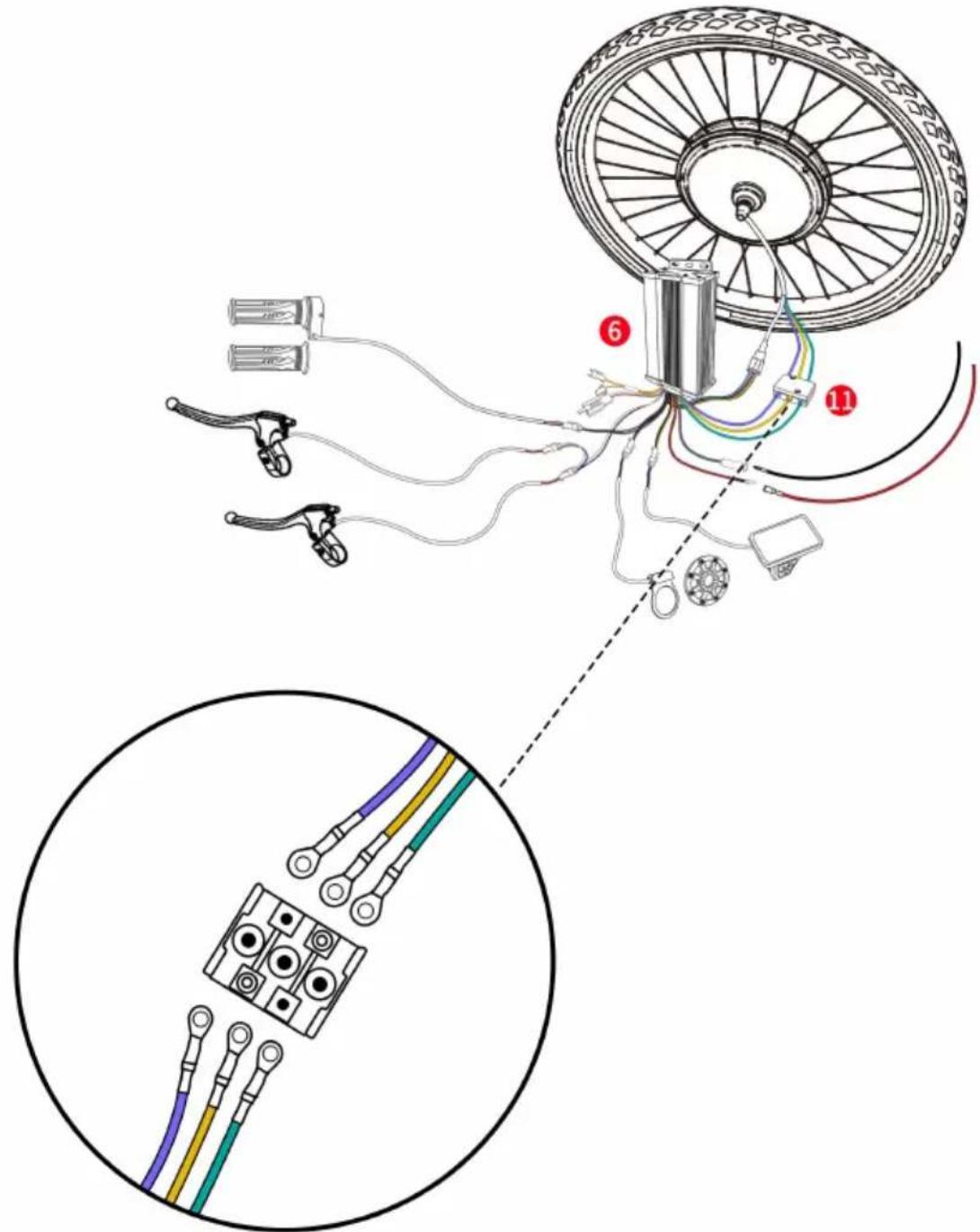
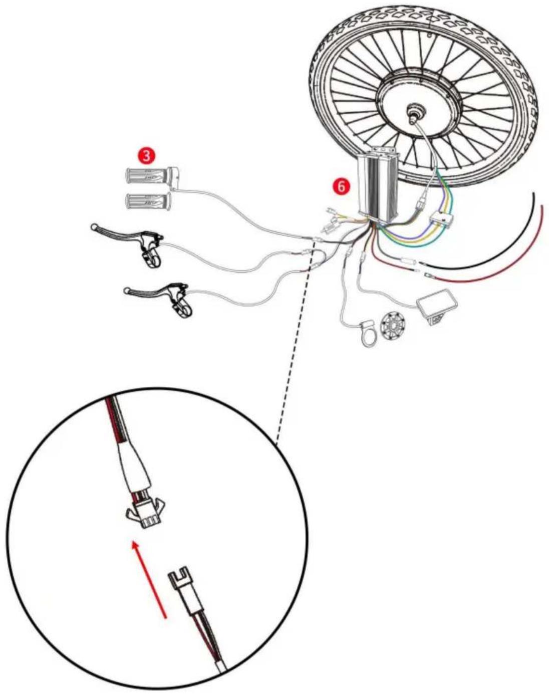
Connect the wires of the front motor wheel and the controller bc
(Note: When connect the wires, arrow signs of both sides should align with each other.)
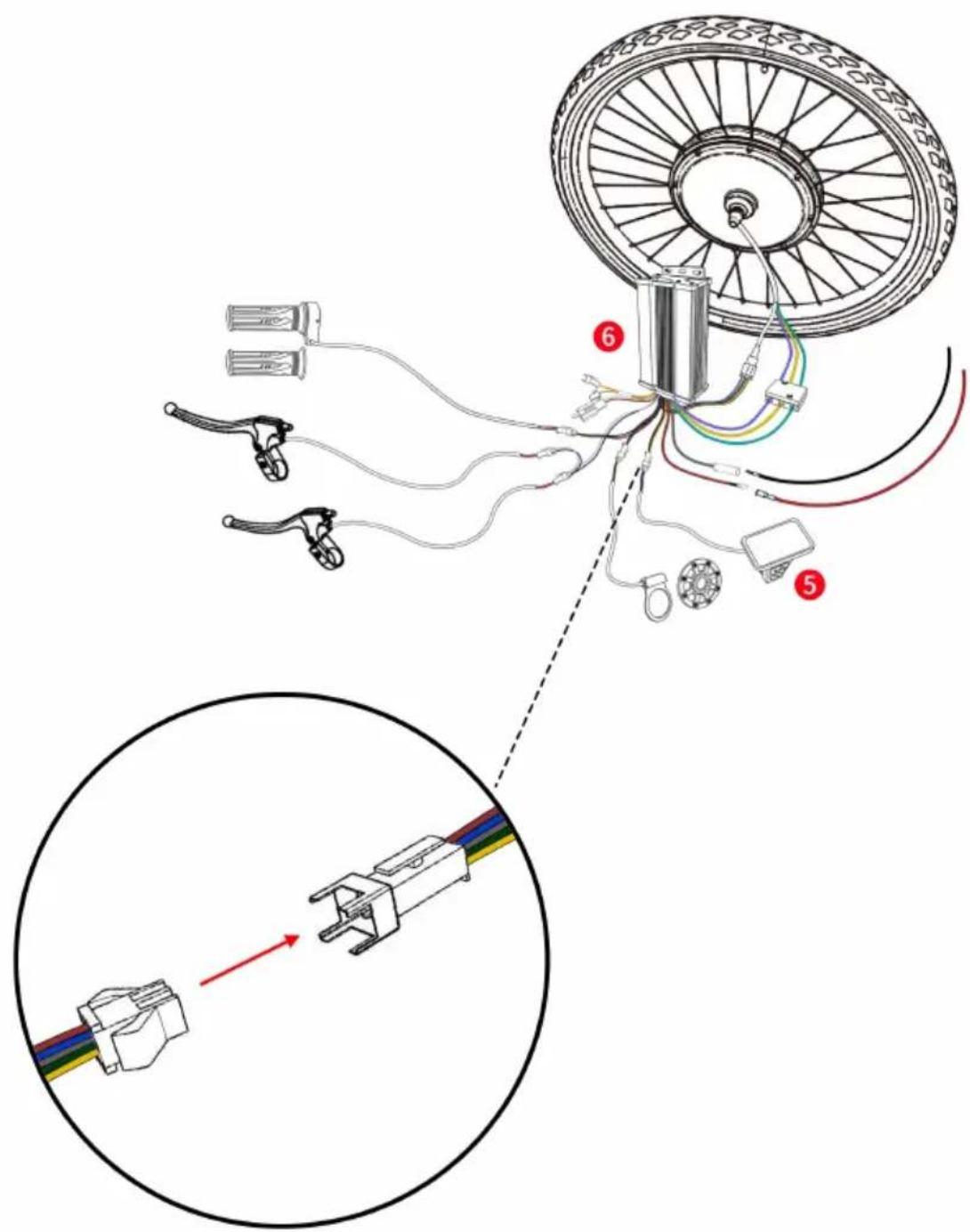
Connect the corresponding connectors of the controller and connectors of the display.
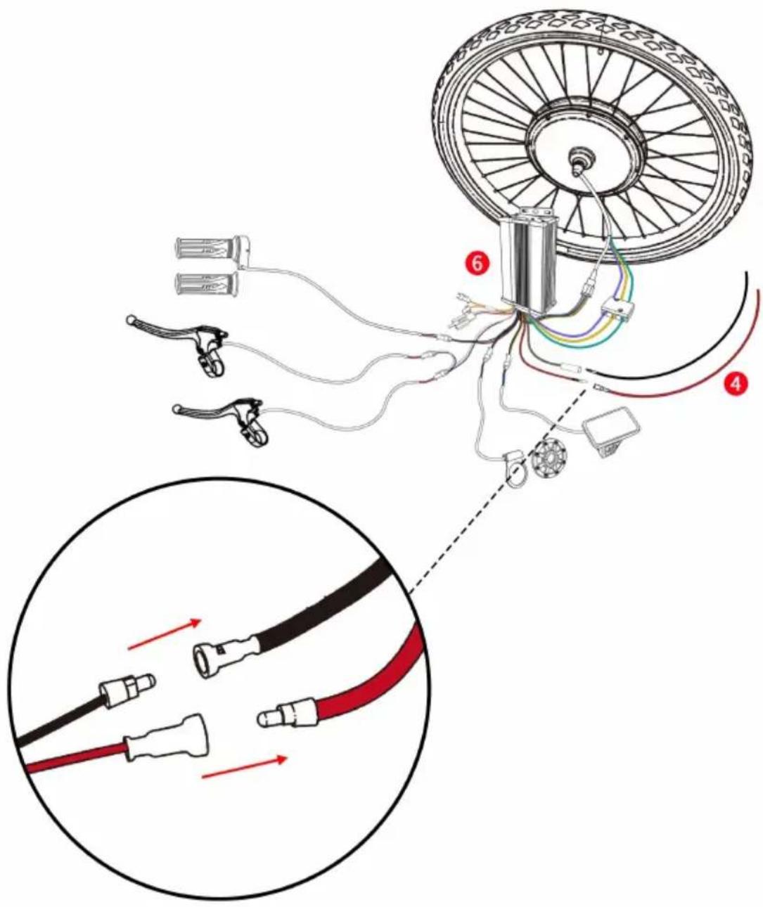
Connect the power cable to the controller as shown.
Note:
- The battery for the controller is not included in this product.Customer need buy it separately.
- The battery must be turned off first before being connected to the wire.
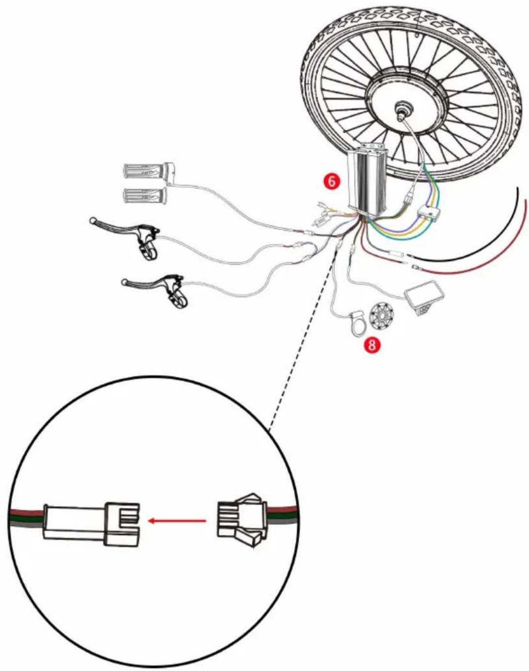
Connect the wires of the controller and the PAS.
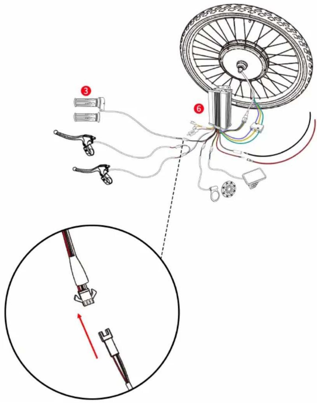
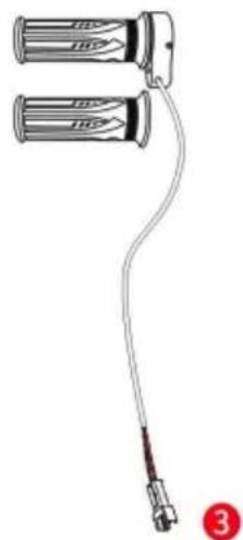
Connect the wires of the controller and the throttle
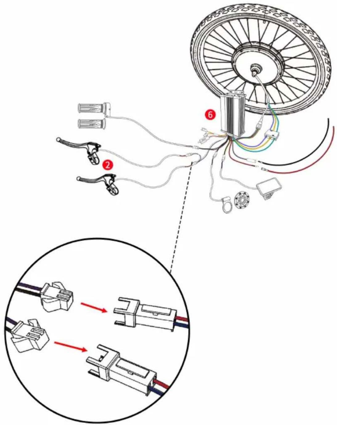
Connect the wires of the controller and the two brake levers.
Installing the Motor Wheel onto Your Bike
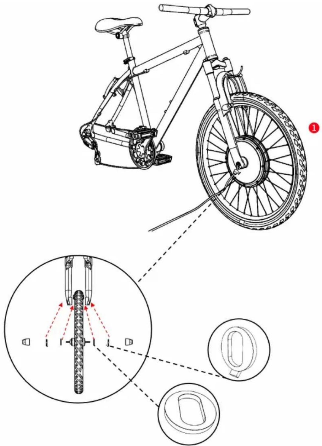
- Ensure washers are installed on each side of the wheel respective (the washers are preinstalled on the wheel.)
- Install the wheel on the front side of your bike as shown.
- Use the washers and nuts to secure the motor wheel.
Installing the Brake Levers
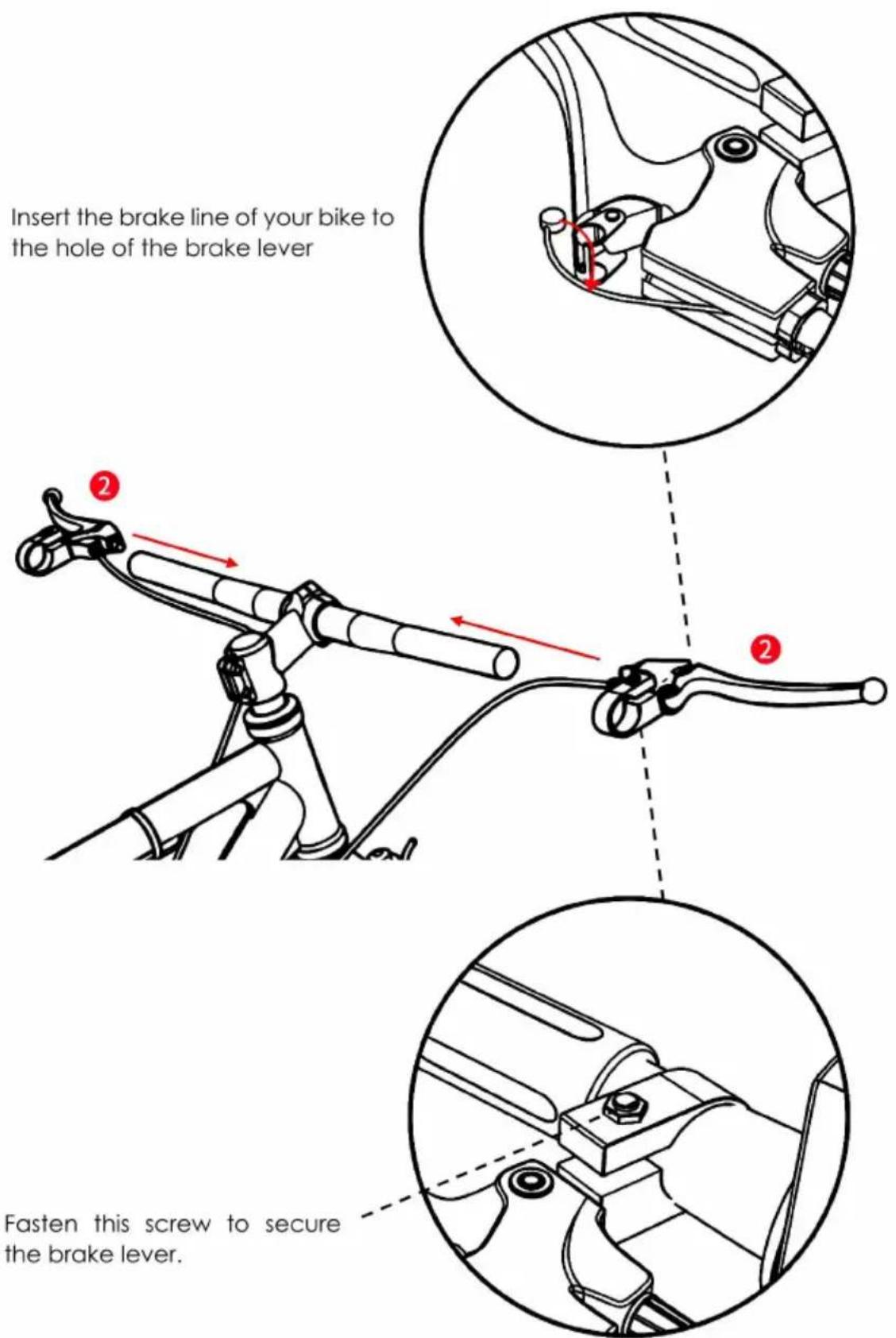
Install the brake levers on your bike handles of both sides.
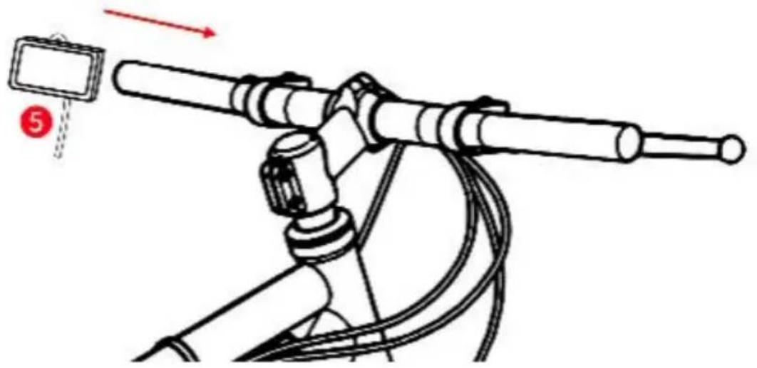
Installing the Operation Panel
natural_image
Diagram of a mechanical device with lever and cable, no text or symbols presentInstall the operation panel on your bike handle as shown.
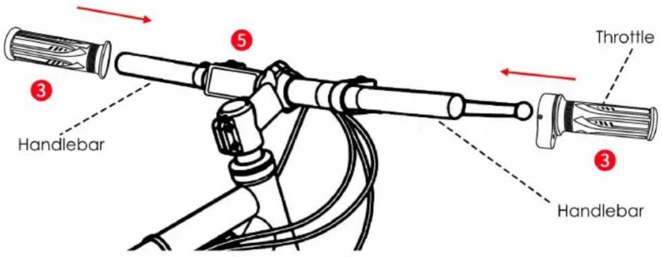
Install the handlebars &throttle as shown.
Installing PAS
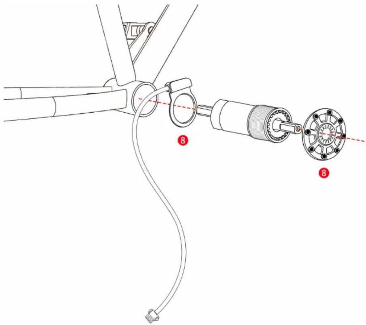
Uninstall the pedal from your bike. After that, install the PAS components as shown.
Ensure the parts are tightly fastened.
Note: PAS is suitable for square tapered bottom bracket interface,JIS standard bicycle tension bowls.If non-JIS standard bicycle users use the product,users need to have some modification ability.It is necessary to the power-assist sensor between the frame and the bowl of the sky center,and the power-assist disk is fixed on the rotating axle or gear disk,otherwise it will lead to unsuccessful installation,and this product can not work properly.
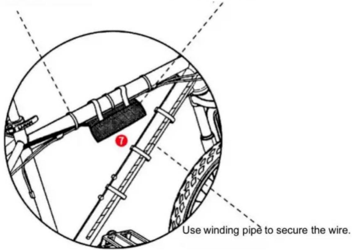
Binding Up the Wires
Use wire ties to secure the wires.
You can put the controller in the controller bag and fasten it on the frame of your bike

Display operation instructions
1. Function overview and Functional areas
1.1 Function overview
The display offers a variety of features to suit riding needs, including:
- Battery level indicator
- Pedal assist(PAS)level indicator
- Speed (current speed, maximum speed, average speed)
- Mileage display(single and total mileage)
- Walk boost mode
- Error code indicator
• Cruise control indicator
- Personalized parameter settings (e.g. wheel diameter, speed limit, battery power setting and PSA parameter setting, password setting, controller current limit setting, etc.).
• Factory default parameter recovery function
1.2 Functional areas
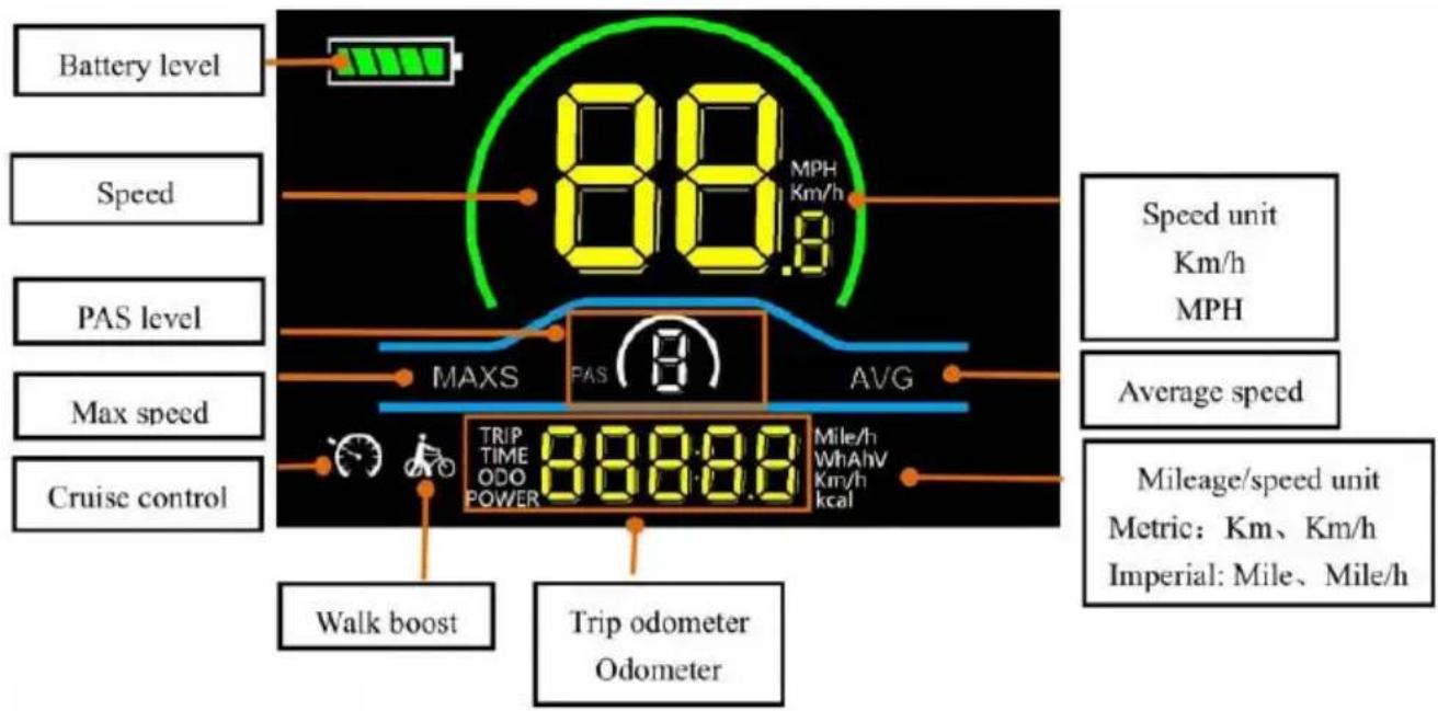
Figure 1-1 Functional area distribution interface
1.3 Button definitionsn
The display is equipped with three buttons on the correcting operating unt power on/off plus and minus . -
2. Routine operation
2.1 Power on/off
Long press power on/off the display. When the display is off, it will not be the battery power and the leakage current is less than IuA .

The display will automatically shut off if it is not used for more than minutes.
2.2 Display interface switching
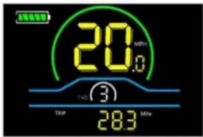
When the display is powered on, it will show the Current Speed (MPH) and Odometer (Mile) by default. Short press to switch between Trip Odometer (Mile), Odometer (Mile), Maximum Speed (MPH), and Average Speed(MPH).
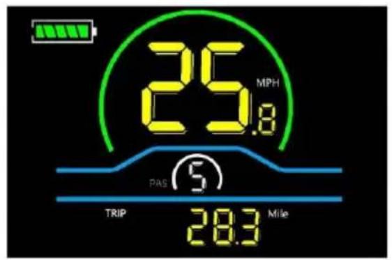
Trip Odometer
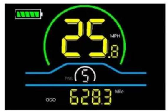
Odometer
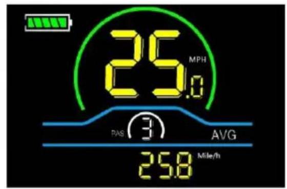
Average Speed
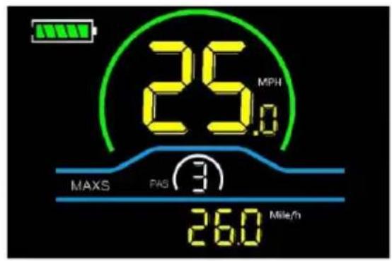
Maximum Speed
Figure 2-1 Display Interface Switching
2.3 Walk boost mode
Long press and ho, the electric bicycle enters the walk boost mode. The electric bicycle will walk at a fixed speed of 6km per hour and the display

Release the button to stop the power output immediately and restore to state before walk boost.
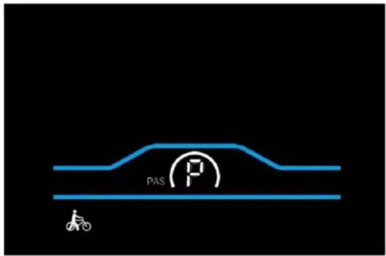
Figure 2-2 Helping to implement the display screen

The walk boost mode can only be used when pushing the electric bicycle, please do not use it while riding.
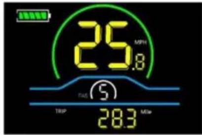
2.4 PAS level selection
Press +to-switch PAS level of electric bicycle, thus changing the motor output power.
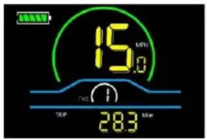
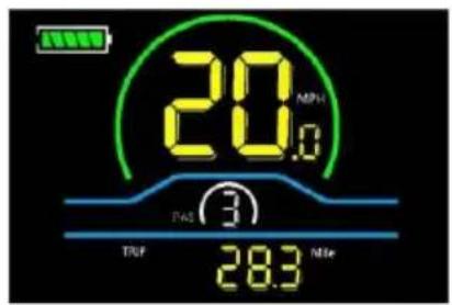
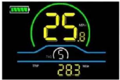
Figure 2-3 PAS level display interface
2.5 Battery level display
The Battery level is shown as 5 bars. When the battery is full charged, all of bars lighten up. When the battery is fully depleted, the bar will begin to flash, warning the user to charge the battery as soon as possible.
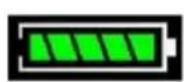


Full power Four bars power Three bars power Two bars power One bar power Empty power flashing
Figure 2-4 Battery Level Display Interface
2.6 Error code display
If there is a fault occurs in the electric system of the electric bicycle, the dis automatically show an error code, see Schedule 1 for a detailed definition of 1 error code.

Figure 2-5 Error Code Display Interface
When the error code appears on the display, please troubleshoot the problem in time, the electric bicycle will not be able to drive normally the problem occurs
3. Personalized parameter settings
Each setting needs to be done with the bicycle stationary. The personalized parameter setting procedure is as follows When the display is ON and the speed shows 0.
The following options are available on the personalized parameter setting interface:
(1) Press and hold and simultaneously for more than 2 seconds to enter the personalized parameter setting interface.
(2) Press + to toggle between the personalized parameter setting interface, and press to enter the parameter changing state.
(3)Press ± to select the parameter, long press for addition operation, long press for subtraction operation.
(4) Press save the parameter settings and return to the personalized parameter setting interface.
(5) Long press to save the parameter settings and exit the personalized parameter setting interface.
Note : Please do not change the parameter settings! If the product does no due to changing the parameter settings, please refer to the factory default parameter for setting.
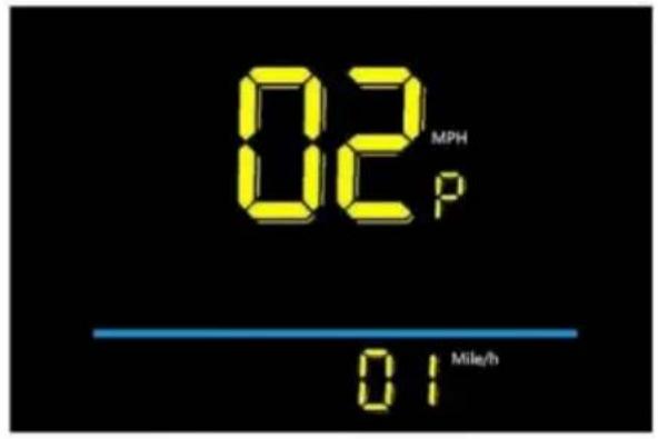
3.1 Backlight luminance setting
01P refers to the backlight luminance setting option. The adjustable range is: 01 for the minimum luminance. 02 for the standard luminance, 03 for the maximum luminance. The factory default setting is 03.
Press to enter the parameter changing state. Press the / select the parameter and press to save the parameter setting and return to the personalized parameter setting interface.

Figure 3-1 Backlight luminance setting interface
3.2 Metric and Imperial setting
02P is the metric and imperial setting option, 00 for metric and 01 for imperia. Press to enter the parameter changing state. Press the + to select the parameter and press to save the parameter setting and return to the personalized parameter setting interface.
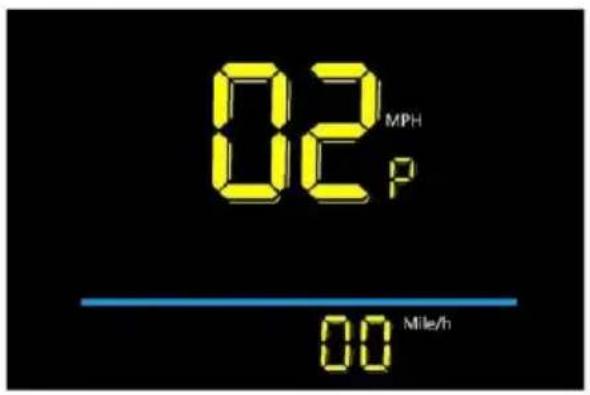
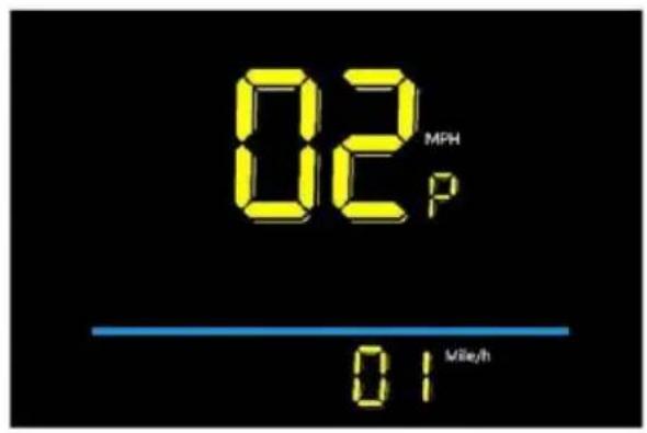
Metric display interface Imperial display interface
Figure 3-2 Metric and Imperial Units Setting Interface
3.3 Rated voltage setting
03P is the rated voltage setting option. The available rated voltage range is:24V/36V/48V. The factory default setting is 48V.
Press enter the parameter changing state. Press then select the parameter and press to save the parameter setting and return to the personalized parameter setting interface.
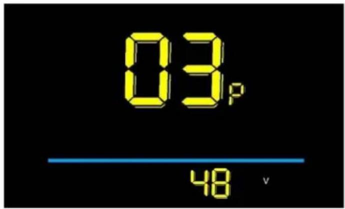
Figure 3-3 Rated voltage setting interface
3.4 Auto Sleep Time Setting
04P is the auto sleep time setting. To save the battery power and reach high range, this display will be turned off after it has not been used for a time. adjustable range is: 1\~60min,00 means no auto shutdown. The factory default setting is 10 minutes.
Press to enter the parameter changing state. Press the select the
parameter and press to save the parameter setting and return to the personalized parameter setting interface.
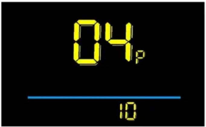
Figure 3-4 Auto Power Off Time Setting Interface
3.5 PAS level setting
05P is the Pedal assist(PAS)level setting option. The available Pedal assist level setting are: 01\~3, 11\~3, 01\~5, 11\~5. The factory default setting is 01\~5.
Press to enter the parameter changing state. Press the + - select the parameter and press to save the parameter setting and return to the personalized parameter setting interface.

Figure 3-5 PAS level setting interface
3.6 Wheel diameter setting
06P is the wheel diameter setting option. Unit: inch, accuracy: 0.1, The adjust wheel diameter range is : 0\~50inch. The factory default setting is 26 inch.
Press to enter the parameter changing state. Press the / - select the parameter and press to save the parameter setting and return to the personalized parameter setting interface.
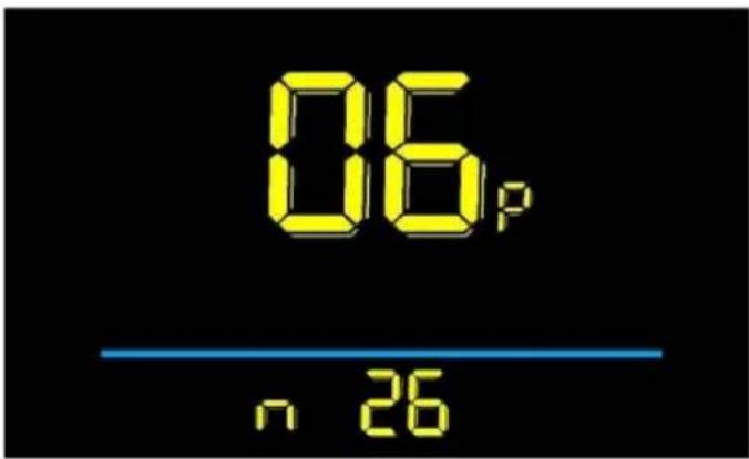
Figure 3-6 Wheel diameter setting interface
3.7 Number of speed sensor magnets setting
07P is the speed sensor magnet number setting option. The adjustable spec sensor magnet number range is: 01\~255pcs. The factory default setting is 46| Changing the settings will cause the speed to be displayed incorrectly.
Press enter the parameter changing state. Press the / select the parameter and press to save the parameter setting and return to the personalized parameter setting interface.
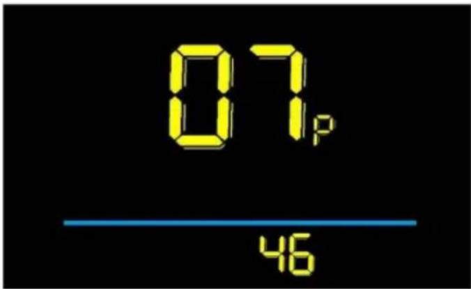
Figure 3-7 Number of speed sensor magnets setting interface 3.8 Speed limit setting
08P is the speed limit setting option. Change this value to set the maximum speed of the electric vehicle; The adjustable speed limit range is: 0\~100%, 100% means no speed limit. The factory default setting is 100%. If you need to s speed limit, please set it proportionally when the battery is fully charged and load, because the type of battery is different, such as ternary lithium battery, I iron phosphate battery, lead-acid battery, the voltage of the full charge is differ and the final maximum speed will be different. For example, the voltage of a
charged 48V ternary lithium battery is 54.6V, and the maximum no-load speed this product is 46mph. If the speed limit is set to 50% , the maximum no-load is 23 mph. Note that there is an error in the speed limit setting of this pro regulations clearly state that a certain speed cannot be exceeded, please set smaller value to comply with the regulations! If the unit of meter display is I the setting value of this item is 0 - 100% , 100 means no speed limit, similarly 50% means half of the maximum speed.
Press to enter the parameter changing state. Press the / select the parameter and press to save the parameter setting and return to the personalized parameter setting interface.
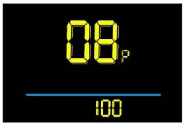
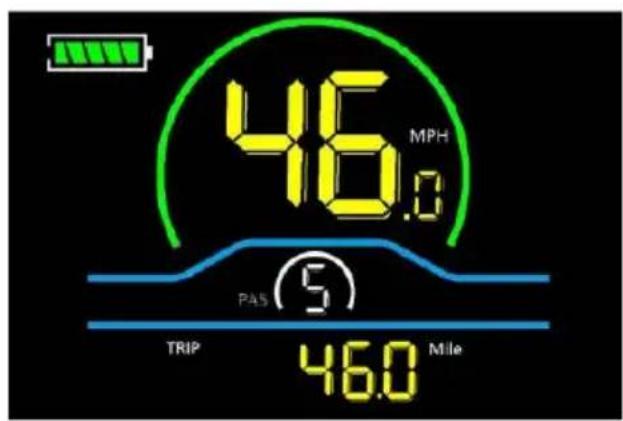
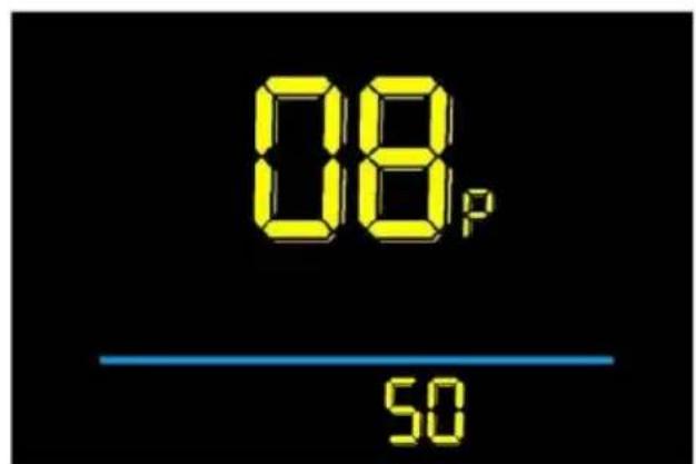
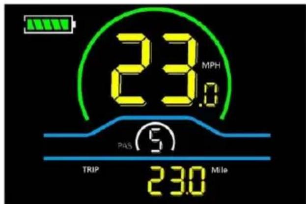
Figure 3-8 Speed limit setting interface
3.9 Start-up setting
09P is the start-up setting option. The display can choose the following start r 00→zero start,01→non-zero start. The factory default setting is 00.Zero start: no need for foot pedal assistance,the throttle can work directly; Non-zero start: T throttle can only work after the foot pedal is assisted.
Press to enter the parameter changing state. Press the + - select the
parameter and press to save the parameter setting and return to the personalized parameter setting interface.
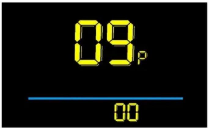
Figure 3-9 Start-up setting interface
3.10 Drive mode setting
10P is the drive mode setting option. The available drive modes are: 00→Pedal assist only,01→Electric only,02 Both Pedal and assist electric. The factory default setting is 02.
Press enter the parameter changing state. Press the - select the parameter and press to save the parameter setting and return to the personalized parameter setting interface.
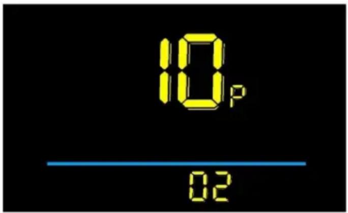
Figure 3-10 Drive mode setting interface
3.11 Pedal assist sensitivity setting
11P is the pedal assist sensitivity setting option. This setting is used for the controller to detect how many pulses the disk has rotated before allowing the motor to operate. The smaller the value, the higher the sensitivity, and the larger value, the lower the sensitivity. For example, a setting of 2 means that the moto
operate after the disk has rotated for 2 pulses, and a setting of 8 means that motor will operate after the disk has rotated for 8 pulses. It can also be inte as the angle of crank rotation when pedaling, the smaller the value the smaller angle, the larger the value, the larger the angle. The adjustable range is 1\~24. The factory default setting is 3. It is not recommended to set the value less than
Press to enter the parameter changing state. Press the 7 select the parameter and press to save the parameter setting and return to the personalized parameter setting interface.

Figure 3-11 Pedal assist sensitivity setting interface
3.12 Pedal assist strength setting
12P is the power start strength setting option, adjustable range is 0\~5, when set 0, it means the motor start power is the weakest after pedaling, when set to 5 means the motor start power is the strongest after pedaling, the factory default setting is 2. The bigger the value is, the more you need to ride the control all value is not recommended to be more than 3, pay attention to the safety of when it's more than 2!
Press to enter the parameter changing state. Press the 7 to select the parameter and press to save the parameter setting and return to the personalized parameter setting interface.
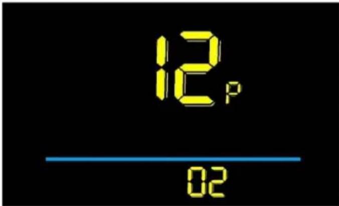
Figure 3-12 Pedal assist strength setting interface
3.13 Number of pedal assist sensor magnets setting
13P is a setting for the number of magnets on the booster disk, which can be adjusted from 5 to 15. The factory default setting is 8. The factory default setting is 8. There is no need to modify this option for this product, as it will cause the not to work. It should only be adjusted if the user replaces the disk with and disk that does not have 8 magnets!
Press to enter the parameter changing state. Press the + - select the parameter and press to save the parameter setting and return to the personalized parameter setting interface.
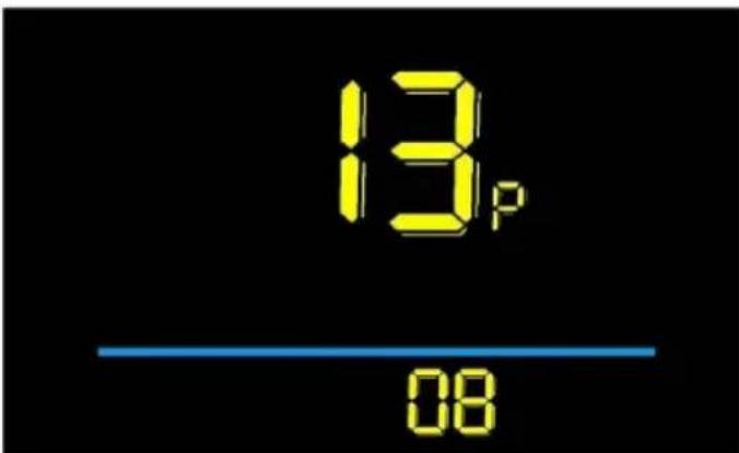
Figure 3-13 Number of Pedal assist sensor magnets setting interface
3.14 Controller Current Limit Setting
14P is the controller current limit setting option. The adjustable range is: 1\~5 The factory default setting is 26A.this product can not be set by the user,mu with the factory settings.
Press enter the parameter changing state. Press the - select the
parameter and press to save the parameter setting and return to the personalized parameter setting interface.
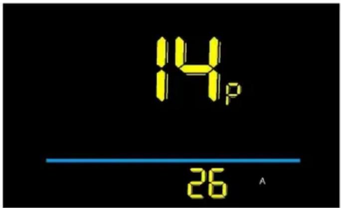
Figure 3-14 Controller Current limit setting interface
3.15 Number of pedal assist sensor magnets setting
15P is the controller under voltage value setting option. The factory default set is 40V.
Press to enter the parameter changing state. Press the + - select the parameter and press to save the parameter setting and return to the personalized parameter setting interface.
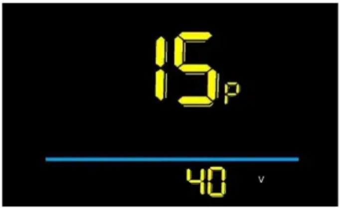
Figure 3-15 Controller under voltage value setting interface
3.16 ODO reset operation
16P is the odometer reset setting option.Optional 00 \ 01. When set to 01,th mileage will be reset to zero.
Press to enter the parameter changing state. Press the + - select the parameter and press to save the parameter setting and return to the
personalized parameter setting interface.
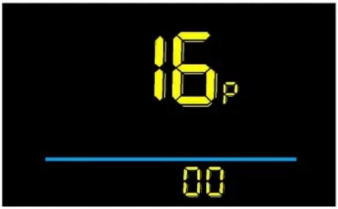
Figure 3-16 ODO reset operation
If you need to reset the mileage for a single ride, press and hold at the same time after powering it on.
3.17 Cruise enable setting
17P is the cruise enable setting option,00 means disable cruise,01 means enable cruise,the default setting is 00.when this setting is 01,during normal riding,the handlebar stays still,long press the meter button for about 3S to enter the cruise state at the current speed,at this time,you can release the handlebar,and then when twisting the handlebar or brake again,the cruise state will be lifted.The function is only valid for the handlebar,the pedals can not be used.
Press to enter the parameter changing state. Press the + - select the parameter and press to save the parameter setting and return to the personalized parameter setting interface.

Figure 3-17 Cruise enable setting interface
3.18 Promotion function setting
18P is the promotion function setting option.00 represents on 6km, 01 represent 6km. The factory default setting is 01.
Press to enter the parameter changing state. Press the + - select the parameter and press to save the parameter setting and return to the personalized parameter setting interface.
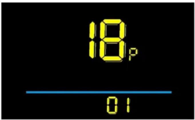
Figure 3-18 Promotion function setting interface
4. Precautions
Pay attention to all the general operating when using the products and not p and unplug the display while it is powered on.
◆ Avoid bumping to all the general operating when using the products and plug and unplug the display while it is powered on.
◆Please do not change the parameter settings at will, otherwise normal riding cannot be guaranteed.
◆If display does not work properly, please send it to the repair center as soon possible.
◆ There may be differences between the physical products and this manual to normal upgrade. Please refer to the physical products.
5. Error Code Definition
| Error code | Definition | Error code | Definition | |
| E001 | Controller failure | E004 | Throttle failure | |
| E002 | Communication failure | E005 | Brake failure | |
| E003 | Hall failure | E006 | Motor phase failure |

Comply with the European security certification.
6. CORRECT DISPOSAL
This product is subject to the provision of european Directive 2012/19/EU. The symbol showing a wheelie bin crossed through indicates that the product requires separate refuse collection in the
European Union. This applies to the product and all accessories marked with a symbol. Products marked as such may not be discarded with normal domestic waste, but must be taken to a collection point for recycling electrical and electric devices.
Manufacturer: Shanghaimuxinmuyeyouxiangongsi
Address: Shuangchenglu 803nong11hao1602A-1609shi, baoshanqu, shanghai 200000 CN.
Imported to AUS: SIHAO PTY LTD. 1 ROKEVA STREETEASTWOOD NSW 2 Australia
Imported to USA: Sanven Technology Ltd. Suite 250, 9166 Anaheim Place, Rancho Cucamonga, CA 91730
Made In China
| UK | REP |
YH CONSULTING LIMITED.
C/O YH Consulting Limited Office 147,
Centurion House, London Road,
Staines-upon-Thames, Surrey, TW18 4A
| EC | REP |
E-CrossStu GmbH
Mainzer Landstr.69, 60329 Frankfurt am
Main.
VEVOR®
TOUGH TOOLS, HALF PRICE
Technical Support and E-Warranty Certificate
www.vevor.com/support
VEVOR®
TOUGH TOOLS, HALF PRICE
natural_image
Diagram of bicycle wheel wiring and accessories (no text or symbols)BESOIN D'AIDE? CONTACTEZ-NOUS!
natural_image
Technical line drawing of a mechanical component with no visible text or symbols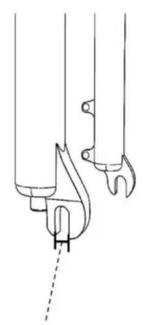
natural_image
Technical line drawing of a mechanical component with no visible text or symbolsLargeur de l'encocheDistance de la fourche av
natural_image
Line drawing of a bicycle wheel with spokes and a central hub (no text or symbols)Front motor Wheel×1
natural_image
Pure medical catheter or tube diagram without any text, numbers, or symbolsBrake Lever×2

natural_image
Diagram of a cable with two cylindrical components connected by a wire, no text or symbols presentHandlebar×1 pair

natural_image
Two curved lines, one red and one black, with no text or symbols4
Power Cable×2

natural_image
Line drawing of a handheld electronic device with a curved cable and connector (no text or symbols)Display×1

natural_image
Diagram of a heat exchanger with multiple colored wires and connectors (no text or labels)Controller×1

natural_image
Top-down view of a black athletic device with white straps and a circular button (no text or symbols)7
Controller Bag×1

natural_image
Technical line drawing of a mechanical component with a loop and circular housing (no text or symbols)PAS×1

natural_image
Simple diagonal line with no text, numbers, or symbolsWinding Pipe×1

10
Wire Tie×1 set
11
Junction Box×1
natural_image
Diagram of a mechanical device with lever and cable, no text or symbols presentUse wire ties to secure the wires. You can put the controller in the controller bag and fasten it on the frame of your bike

C/O YH Consulting Limited Bureau 147,
Staines-upon-Thames, Surrey, TW18 4AX
E-CrossStu GmbH
Mainzer Landstr.69, 60329 Francfort-sur-le-Main
Principal.
VEVOR®
TOUGH TOOLS, HALF PRICE
natural_image
Diagram of bicycle wheel wiring and accessories (no text or symbols)natural_image
Technical line drawing of a mechanical component with no visible text or symbols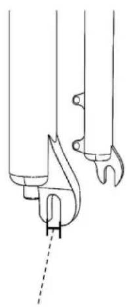
natural_image
Technical line drawing of a mechanical component with no visible text or symbolsnatural_image
Line drawing of a bicycle wheel with spokes and a central hub (no text or symbols)Front motor Wheel×1

natural_image
Pure line drawing of a medical or laboratory device with no text, numbers, or symbolsBrake Lever×2

natural_image
Diagram of a cable with two cylindrical components connected by a wire, no text or symbols presentHandlebar×1 pair
natural_image
Two curved lines, one red and one black, with no text or symbols4
Power Cable×2
natural_image
Line drawing of a handheld electronic device with a curved cable and connector (no text or symbols)Display×1

natural_image
Diagram of a heat exchanger with multiple colored wires and connectors (no text or labels)Controller×1
natural_image
Top-down view of a black athletic device with white straps and a circular button (no text or symbols)7
Controller Bag×1

natural_image
Technical line drawing of a mechanical component with a loop and circular housing (no text or symbols)PAS×1

natural_image
Simple diagonal line with no text, numbers, or symbolsWinding Pipe×1

10
Wire Tie×1 set

11
Junction Box×1
Montageanleitung
natural_image
Diagram of a mechanical device with lever and cable, no text or symbols present
C/O YH Consulting Limited Office 147,
Centurion House, London Road,
Staines-upon-Thames, Surrey, TW18 4AX
www.vevor.com/support
VEVOR®
TOUGH TOOLS, HALF PRICE
natural_image
Diagram of bicycle wheel wiring and accessories (no text or symbols)natural_image
Technical line drawing of a mechanical component with no visible text or symbols
natural_image
Technical line drawing of a mechanical component with no visible text or symbolsnatural_image
Line drawing of a bicycle wheel with spokes and a central hub (no text or symbols)Front motor Wheel×1

natural_image
Pure line drawing of a medical or laboratory device with no text, numbers, or symbolsBrake Lever×2

natural_image
Diagram of a cable with two cylindrical components connected by a wire, no text or symbols presentHandlebar×1 pair

natural_image
Two curved lines, one red and one black, with no text or symbols4
Power Cable×2

natural_image
Line drawing of a handheld electronic device with a curved cable and connector (no text or symbols)Display×1

natural_image
Diagram of a heat exchanger with multiple colored wires and connectors (no text or labels)Controller×1

natural_image
Top-down view of a black athletic device with white straps and a circular button (no text or symbols)7
Controller Bag×1

natural_image
Technical line drawing of a mechanical component with a loop and circular housing (no text or symbols)PAS×1

natural_image
Simple diagonal line with no text, numbers, or symbolsWinding Pipe×1

10
Wire Tie×1 set

11
Junction Box×1
Collegare i fili del controller e del PAS.
natural_image
Diagram of a mechanical device with lever and cable, no text or symbols presentUse wire ties to secure the wires. You can put the controller in the controller bag and fasten it on the frame of your bike

Importato in AUS: SIHAO PTY LTD. 1 ROKEVA STREETEASTWOOD NSW 2122 Australia
Importato negli USA: Sanven Technology Ltd. Suite 250, 9166 Anaheim Place, Rancho Cucamonga, CA 91730
Made in China
CONSULENZA YH LIMITATA.
C/O YH Consulting Limited Ufficio 147,
Casa del centurione, London Road,
Staines-upon-Thames, Surrey, TW18 4AX
elettronica www.vevor.com/support
VEVOR®
TOUGH TOOLS, HALF PRICE
natural_image
Diagram of bicycle wheel wiring and accessories (no text or symbols)natural_image
Line drawing of a bicycle wheel with spokes and a central hub (no text or symbols)Front motor Wheel×1

natural_image
Pure line drawing of a medical or laboratory device with no text, numbers, or symbolsBrake Lever×2

natural_image
Diagram of a cable with two cylindrical components connected by a wire, no text or symbols presentHandlebar×1 pair

natural_image
Two curved lines, one red and one black, with no text or symbols4
Power Cable×2

natural_image
Line drawing of a handheld electronic device with a curved cable and connector (no text or symbols)Display×1

natural_image
Diagram of a heat exchanger with multiple colored wires and connectors (no text or labels)Controller×1

natural_image
Top-down view of a black athletic device with white straps and a circular button (no text or symbols)7
Controller Bag×1
natural_image
Technical line drawing of a mechanical component with a loop and circular housing (no text or symbols)PAS×1

natural_image
Simple diagonal line with no text, numbers, or symbolsWinding Pipe×1

10
Wire Tie×1 set

11
Junction Box×1
natural_image
Diagram of a mechanical device with lever and cable, showing motion direction (no text or symbols)Casa Centurión, London Road,
Staines-upon-Thames, Surrey, TW18 4AX
E-CrossStu GmbH
natural_image
Diagram of bicycle wheel wiring and accessories (no text or symbols)POTRZEBUJESZ POMOCY? SKONTAKTUJ SIĘ Z NAMI!
natural_image
Technical line drawing of a mechanical component with no visible text or symbols
natural_image
Technical line drawing of a mechanical component with no visible text or symbolsnatural_image
Line drawing of a bicycle wheel with spokes and a central hub (no text or symbols)Front motor Wheel×1

natural_image
Pure line drawing of a medical or laboratory device with no text, numbers, or symbolsBrake Lever×2

natural_image
Diagram of a cable with two cylindrical components connected by a wire, no text or symbols presentHandlebar×1 pair

natural_image
Two curved lines, one red and one black, with no text or symbols4
Power Cable×2

natural_image
Line drawing of a handheld electronic device with a curved cable and connector (no text or symbols)Display×1

natural_image
Diagram of a heat exchanger with multiple colored wires and connectors (no text or labels)Controller×1

natural_image
Top-down view of a black athletic device with white straps and a circular button (no text or symbols)7
Controller Bag×1

natural_image
Technical line drawing of a mechanical component with a loop and circular housing (no text or symbols)PAS×1

natural_image
Simple diagonal line with no text, numbers, or symbolsWinding Pipe×1

10
Wire Tie×1 set

11
Junction Box×1
Instrukcje montażu

natural_image
Diagram of a mechanical device with lever and cable, no text or symbols present
C/O YH Consulting Limited Biuro 147, Dom Centuriona, London Road,
Staines-upon-Thames, Surrey, TW18 4AX
| Przedstawiciel UE |
E-CrossStu GmbH
natural_image
Diagram of bicycle wheel wiring and accessories (no text or symbols)HULP NODIG? NEEM CONTACT MET ONS OP!
natural_image
Technical line drawing of a mechanical component with no visible text or symbols
natural_image
Technical line drawing of a mechanical component with no visible text or symbolsnatural_image
Line drawing of a bicycle wheel with spokes and hub (no text or symbols)Front motor Wheel×1

natural_image
Pure line drawing of a medical or laboratory device with no text, numbers, or symbolsBrake Lever×2

natural_image
Diagram of a cable with two cylindrical components connected by a wire, no text or symbols presentHandlebar×1 pair

natural_image
Two curved lines, one red and one black, with no text or symbols4
Power Cable×2

natural_image
Line drawing of a handheld electronic device with a curved cable and connector (no text or symbols)Display×1
natural_image
Diagram of a heat exchanger with multiple colored wires and connectors (no text or labels)Controller×1

natural_image
Top-down view of a black athletic device with white straps and a circular button (no text or symbols)7
Controller Bag×1

natural_image
Technical line drawing of a mechanical component with a loop and circular housing (no text or symbols)PAS×1
natural_image
Simple diagonal line with no text, numbers, or symbolsWinding Pipe×1

10
Wire Tie×1 set

11
Junction Box×1
Montage-instructies
natural_image
Diagram of a mechanical device with lever and cable, no text or symbols presentMaximum Speed
Figuur 2-1 Display-interface schakelen
2.3 Wandelboostmodus
Als u de knop lang

instelling is 10 minuten.
Pers

C/O YH Consulting Limited Kantoor 147,
Centurionhuis, Londen Road,
Staines-upon-Thames, Surrey, TW18 4AX
E-CrossStu GmbH
Mainzer Landstr.69, 60329 Frankfurt am
Voornaamst.
VEVOR®
TOUGH TOOLS, HALF PRICE
garantiecertificaat www.vevor.com/support
VEVOR®
TOUGH TOOLS, HALF PRICE
natural_image
Diagram of bicycle wheel wiring and accessories (no text or symbols)BEHÖVER HJÄLP? KONTAKTA OSS!
natural_image
Technical line drawing of a mechanical component with no visible text or symbols
natural_image
Technical line drawing of a mechanical component with no visible text or symbolsNaggbreddFramgaffelavständ

natural_image
Line drawing of a bicycle wheel with spokes and a central hub (no text or symbols)Front motor Wheel×1

natural_image
Pure line drawing of a medical or laboratory device with no text, numbers, or symbolsBrake Lever×2
natural_image
Diagram of a cable with two cylindrical components connected by a wire, no text or symbols presentHandlebar×1 pair

natural_image
Two curved lines, one red and one black, with no text or symbols4
Power Cable×2

natural_image
Line drawing of a handheld electronic device with a curved cable and connector (no text or symbols)Display×1

natural_image
Diagram of a heat exchanger with multiple colored wires connected to a battery pack (no text or labels visible)Controller×1

natural_image
Top-down view of a black athletic device with white straps and a circular button (no text or symbols)7
Controller Bag×1

natural_image
Technical line drawing of a mechanical component with a loop and circular housing (no text or symbols)PAS×1

natural_image
Simple diagonal line with no text, numbers, or symbolsWinding Pipe×1
10
Wire Tie×1 set
11
Junction Box×1
natural_image
Diagram of a mechanical device with lever and cable, no text or symbols presentVisa driftsinstruktioner
C/O YH Consulting Limited Office 147,
Centurion House, London Road,
Staines-upon-Thames, Surrey, TW18 4AX
| EC | REP |
E-CrossStu GmbH
Mainzer Landstr.69, 60329 Frankfurt am
Main.
VEVOR®
TOUGH TOOLS, HALF PRICE
www.vevor.com/support