SCA-80W - Heating Vevor - Free user manual and instructions
Find the device manual for free SCA-80W Vevor in PDF.

| Product Type | Electric Sauna Heater |
| Model | SCA-80W |
| Brand | VEVOR |
| Rated Power | 8 kW |
| Supply Voltage | 400 V 3N ~ 50/60 Hz |
| Temperature Range | 35-110 °C |
| Recommended Sauna Volume | 8-12 m³ (282-424 ft³) |
| Minimum Cabin Height | 190 cm |
| Minimum Distance to Wall | 13 cm from each side and rear |
| Minimum Distance to Ceiling | 110 cm |
| Minimum Distance to Floor | 18 cm |
| Recommended Cable Cross-section | 2.5 mm² |
| Stone Capacity | 10-15 kg |
| Recommended Water Amount per Pour | 50-100 ml |
| Maximum Continuous Use Time | 4 hours (normal mode) |
| Control Panel Functions | Time setting, temperature, delayed start, auto-off |
| Protection | Overheat thermostat with manual reset |
| Mounting Type | Wall-mounted |
| Approximate Weight | 15 kg |
| Warranty | Technical support and electronic warranty certificate |
Frequently Asked Questions - SCA-80W Vevor
User questions about SCA-80W Vevor
0 question about this device. Answer the ones you know or ask your own.
Ask a new question about this device
Download the instructions for your Heating in PDF format for free! Find your manual SCA-80W - Vevor and take your electronic device back in hand. On this page are published all the documents necessary for the use of your device. SCA-80W by Vevor.
USER MANUAL SCA-80W Vevor
Technical Support and E-Warranty Certificate www.vevor.com/support
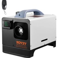
SAUNA HEATER
MODEL:SCA-60W/SCA-80W
We continue to be committed to provide you tools with competitive price. "Save Half", "Half Price" or any other similar expressions used by us only represents an estimate of savings you might benefit from buying certain tools with us compared to the major top brands and does not necessarily mean to co all categories of tools offered by us. You are kindly reminded to verify carefully when you are placing an order with us if you are actually Saving Half in comparison with the top major brands.
Model: SCA-60W/SCA-80W
natural_image
Line drawing of a portable air conditioner unit and its control panel (no text or symbols)NEED HELP? CONTACT US!
Have product questions? Need technical support? Please feel free to contact us:
Technical Support and E-Warranty Certificate www.vevor.com/support
This is the original instruction, please read all manual instructions carefully before operating. VEVOR reserves a clear interpretation of user manual. The appearance of the product shall be subject to product you received. Please forgive us that we won't inform you and there are any technology or software updates on our product.
SAFETY INSTRUCTIONS
- Electrical shock hazard----To avoid electrical shock hazard, all installations and relevant services shall be performed by qualified personnel.
- Sauna bath time should be less than half an hour. Bathing too long cause heart beating too fast, heartache, feeling weak or dizzy. User stop sauna bath immediately as soon as the above symptoms occur.
- Sauna bath may cause tension of bathers. Thus, those who have the symptoms as below, should take sauna bath under direction by Physician:
A. Being pregnant.
B. Having heart disease.
C. Having high blood pressure.
D. Having circulation system disease.
E. After drinking.
F. After taking medicine.
G. Diabetes.
H. Not feeling well.
- Children must be under the company of adult during sauna bath.
- Risk of scald: Must not touch or move the sauna heater during h Stay at least 30cm away from the hot heater.
- Use ordinary drinking water only; It may damage the heating element when water with other materials is poured into the stone compartment which is beyond our guarantee. Do not use any chemically treated water (such as spa or pool water) on the heater any time.
Water no more than 100ml is suggested for each pouring after sauna stones are heated.
- Odors may occur during the first sauna bath as the Anti-rust oil heating elements, which will disappear after sauna heater powers on opening sauna door about 10-15mins.
Symbol Description
| Symbol | Symbol Description |
 | Warning-To reduce the risk of injury, the user must r instructions manual carefully. |
 | Alternating current |
 | This symbol, placed before a safety comment, indicat kind of precaution, warning, or danger. Ignoring this w may lead to an accident. To reduce the risk of injur electrocution, please always follow the recommendation shown below. |
 | Danger!Risk of personal injury or environmental damage! Risk o shock! Risk of personal injury by electric shock! |
 | This product is subject to the provision of European D 2012/ 19/EC. The symbol showing a wheelie bin cro through indicates that the product requires separate re collection in the European Union. This applies to the and all accessories marked with this symbol. Products as such may not be discarded with normal domestic w must be taken to a collection point for recycling electr electronic devices. |
PARAMETER LIST
| Model | SCA-60W | SCA-80W | SCA-90W |
| Voltage | 400V 3N~50/60Hz | 400V 3N~50/60Hz | 400V 3N~50/60Hz |
| Power | 6kW | 8kW | 9kW |
| Temperature Range | 35-110°C | 35-110°C | 35-110°C |
| Applicable Space | 176.5-317.8ft ^3 | 282.5-423.7ft ^3 | 317.8-459ft ^3 |
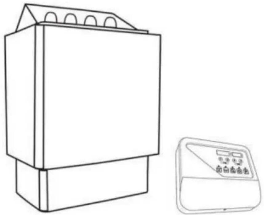
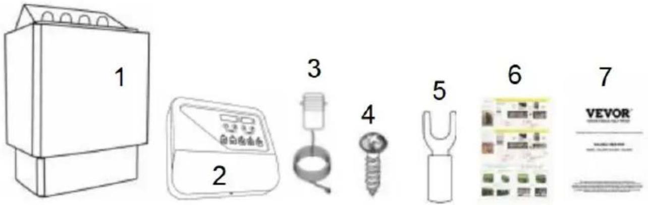
PARTS LIST
| ITEM | DESCRIPTION | QTY |
| 1 | Sauna heater | 1 |
| 2 | Sauna control panel | 1 |
| 3 | Temperature sensor unit | 1 |
| 4 | M4* 12mm Bracket screws (for sauna control pa | 3 |
| M4* 12mm Bracket screws (for temperature sensor | 2 | |
| M6*40mm Bracket screws (for sauna heater) | 2 | |
| M6* 16mm Bracket screws (for sauna heater) | 2 | |
| 5 | Fork terminal ( 10pcs for control panel, 5pcs for heater) | 15 |
| 6 | Instruction poster about wiring and sauna stone p | 1 |
| 7 | Product manual | 1 |
INSTALLATION INSTRUCTIONS
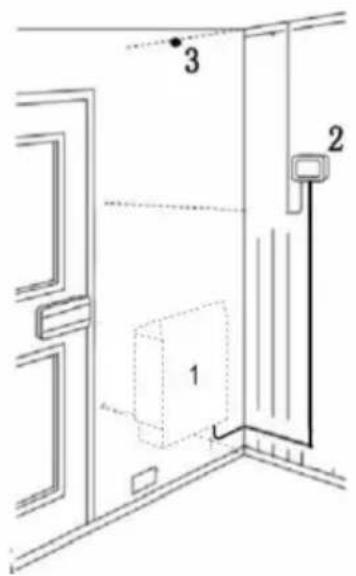
installation diagram of temperature sensor and sauna heater
Temperature sensor and sauna heater must be installed strictly accord to the following diagrams. (See Fig3 and Fig4)
A heat resistant cable of 3 meters is provided with the control panel can be extended to the outside of sauna room by normal weak current cables.
Failure to follow these causes too high temperature and a fire hazard mm).
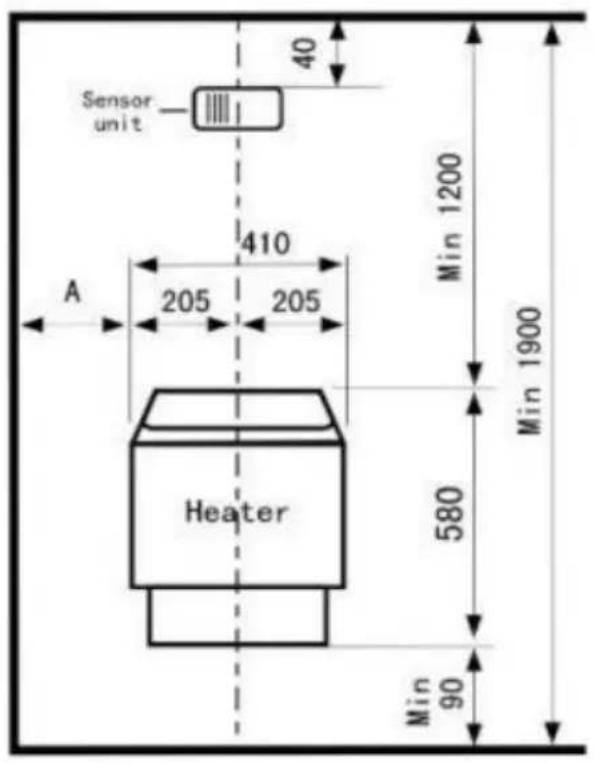
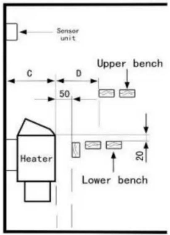
Fig3

Fig4
| Heater | Distance(mm) | ||
| A | C | D | |
| 3kW | 50 | 280 | 80 |
| 4.5kW | 80 | 280 | 100 |
| 6kW | 100 | 280 | 150 |
| 8kW | 130 | 300 | 200 |
| 9kW | 130 | 300 | 200 |
| Model | SCA-30W | SCA45W | SCA-60W | SCA80W | SCA90W | ||
| Power | KW | 3.0 | 4.5 | 6 | 8.0 | 9.0 | |
| Sauna room | Volume (m3) | Min | 2 | 3 | 5 | 8 | 9 |
| Max | 4 | 6 | 9 | 12 | 13 | ||
| Height min.(cm) | 190 | 190 | 190 | 190 | 190 | ||
| Minimum distance from heater to | side & back wall min.(cm) | 5 | 8 | 10 | 13 | 13 | |
| If 500mm over From floor guard rail min.(cm) | 5 | 8 | 15 | 20 | 20 | ||
| Ceiling min.(cm) | 110 | 110 | 110 | 110 | 110 | ||
| Floor Min.(cm) | 18 | 18 | 18 | 18 | 18 | ||
| Cables to | 400V (mm2) | 1.5 | 1.5 | 1.5 | 2.5 | 2.5 | |
Remark: 1. The upper screws must be fastened tight, the minimum distances between screw head and wall is 3 ~mm .
Remark: 2. The wall behind the heater is not allowed to be covered materials like asbestos cement, asbestos board and so on, because the sort of covering layer could cause high temperature and a risk of bu
Remark: 3. Must use qualified materials for the walls and ceiling.
| Model | Power (kW) | Sauna room Volume( m^3 ) | Suggestion heating time | |
| Min | Max | (28-70°C) | ||
| SCA-60W | 6 | 5 | 9 | 30-50min |
| SCA-80W | 8 | 8 | 12 | 30-50min |
| SCA-90W | 9 | 9 | 13 | 30-50min |
| Above suggested heating time should be achieved, including limited to these:1. Room thermometer installed opposite to the sauna heater, clo the ceiling.2. Sauna room is installed indoor with insulation for diffusion pre purpose.3. Temp knob adjust to the Max. | ||||
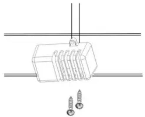
INSTALLATION OF TEMPERATURE SENSOR
- Fasten the sensor unit with screws to the wall straight over sauna inside the sauna room. Check diagram for minimum distance (See fig:
natural_image
Technical line drawing of a mechanical component with two screws and a connecting rod (no text or symbols)- Wire from sensor unit connect to the Power circuit of control panel (Item 1: Sauna heater inside the sauna room, Item 2: Sauna control outside the sauna room, Item 3: Temperature sensor unit inside the sauna room)
LIMIT CONTROL
Fitted as a safety feature is an overheating controller that prevents the heater, in the eventuality of some fault, like problem about wrong installation place of temperature sensor, or problem from thermostat. When the sensor temperature in sauna room reach 130^ C high temperature, the reset link inside the sensor unit automatically cuts of electricity power.
When you fix the problem about overheating, user need to press the link manually
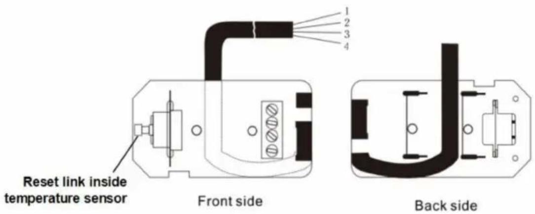
Fig2
GUARD RAIL
Please follow the minimum distances requirements in fig 6 if guardrail desired for the heater.
natural_image
Diagram of a room layout with lighting fixtures and a 60-minute time label (no readable text or symbols)Fig5
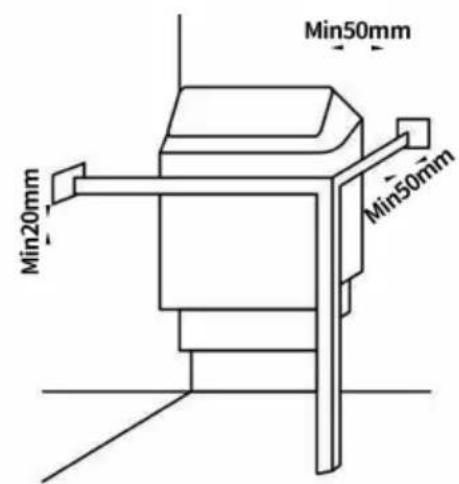
Fig6
The control panel is splash-proof and must be installed outside the sa room, a dry place near sauna room will be suggested.
The temperature sensor unit must be installed to the wall inside the room.
Please follow the minimum safety distance of sauna heater during installation (See fig3), which is included in installation diagram. Failure follow these may cause a burn to the wooden wall.
flowchart
graph TD
    A["1"] --> B["8:00:2"]
    C["2"] --> D["8:00:1"]
    B --> E["H TIME"]
    D --> F["TEMP"]
    E --> G["7"]
    F --> G
    G --> H["6"]
    G --> I["5"]
    G --> J["4"]
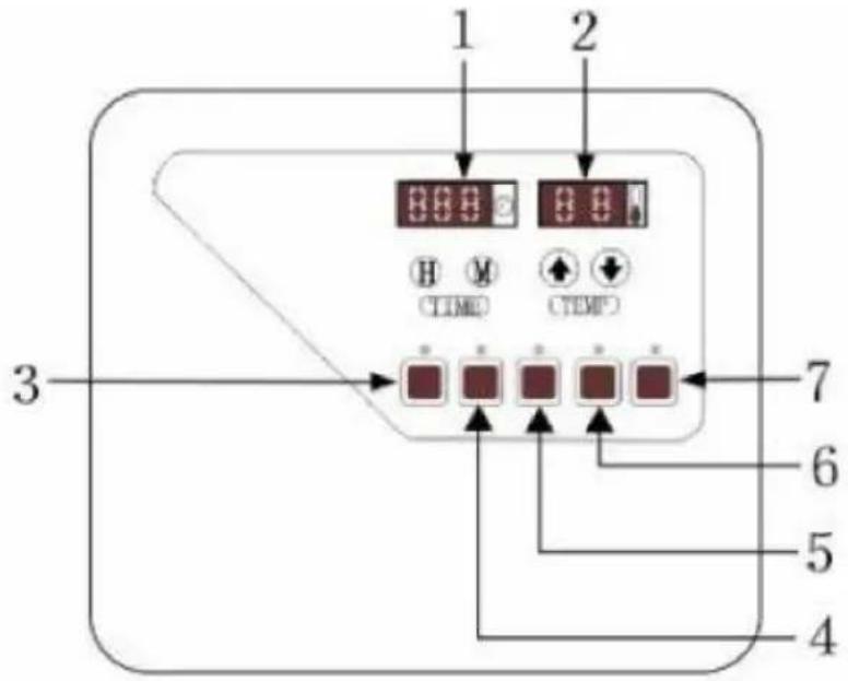
Control panel
Fig1
| ITEM | DESCRIPTION |
| 1 | Time Table |
| 2 | Temperature Table |
| 3 | Prepare to Place |
| 4 | Control Time |
| 5 | Ozone Output (Optional) |
| 6 | Power of Room Light |
| 7 | Power of Heater |
1. Adjust present time:
Press “H” to adjust the hour until the figure comes stable, then press adjust minutes.
2. Set temperature:
Press “P” to set temperature, then press“▲” or “▼”to control the temperature until the figure comes stable after about 3 seconds (setting range 35-110/95-230°F, default temp is°C6040°F)
3. Work mode:
3.1 Normal working mode
Press “P” to start the sauna heater directly, its operation time can la hours.
3.2 Preset working mode
A. Auto-start setting (Max 24hours):
Press “Prepare to place” to fix the time, then press “H” and “M” to before “P” to finish.
B. Auto-Stop setting (Min 10mins, Max 4hours):
Press “Control time” to adjust the time, then press “H” and “M” to s before time table finishing blink.
Remark:
Step 1:3.1 and 3.2.A must be operated during unworking of sauna heater Step 2 :and 3.2.B must be operated during working of sauna heater)
SAUNA ROCKS
It's recommended that all sauna stones should be rinsed to remove a stains or dust. The largest ones should be loaded at the bottom. Do load the stones too tight to block air circulation through the sauna ho New ones should be loaded when the stones get broken or crumbling. Load sufficient sauna rocks(10-15kg) into the sauna heater after finishing the installation of sauna heater and controller.
ATTENTION:
Sauna rocks must be of best quality because temperature inside saur heater is extremely high. Rocks of inferior quality can't withstand heat they may be easily broken or crumbling because of the huge heat changing,
- 10 -which may damage heating elements. Or these stones may cour the
heat circulation because they are easily oxidized, then sauna heater may be damaged while stone being heated or being poured water to vapors.
The time is right for throwing the water on sauna stones when the s are hot enough for complete vaporization of the water, about 1 hour powering on the sauna heater with sauna stones.
Start Small -- Pour only a small amount of water—about half a cup(50-80ml)—onto the rocks atop your electric heater.
Adjust Accordingly -- Gradually increase or decrease the amount pour based on your comfort levels.
Avoid Overdoing it -- If you notice that water runs out from the bottle the heater, it means you have poured too much water or that the st are not hot enough, potentially damaging the unit or creating a safety hazard.
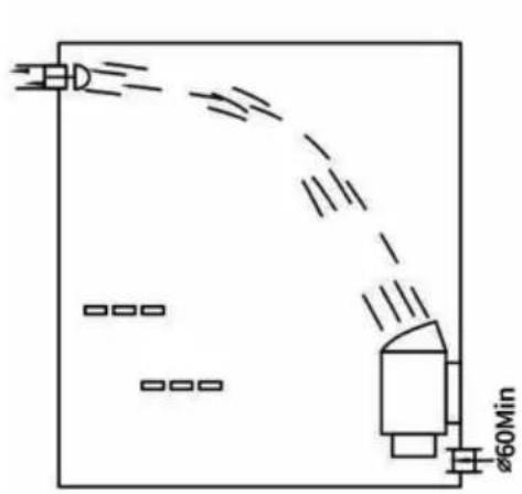
VENTILATION
To have a smoothing sauna bath, there should be a proper mixing c and cold air inside the sauna room. Another reason for ventilation is draw air around the sauna heater and move the heat to farthest par
sauna room.
The inlet vent with diameter more than 6cm should be installed directly below the sauna heater. (See fig 5)
The outlet vent should be installed diagonally opposite to the inlet, its suggested to place under the platform inside the sauna room as far possible from the inlet vent. The diameter of outlet vent should be two big as the inlet, it may be installed far away the floor and under the of the upper bench.
GUARANTEE
The following situation are not guaranteed:
1) Installation or dis-assembly of inside structure by unprofessional personnel;
2) Supply voltage fluctuation range>±10%;
3) Unqualified rocks on sauna heater's operation;
4) Installation without following the dimension instruction inside manual.
TROUBLESHOOTING
| Symptom | Possible cause | Remedy |
| “E1” showed on display panel | Temperature sensor's measuring circuit broken. | Check the wires to the temperature sensor and the connections (see Fig2 and Fig7) for faults. |
| No Heat | Overheat protector's measuring circuit broken. | Press the overheat protector reset link inside the temperature sensor unit. (s Fig2) |
| No light on the display panel | Connection wire between display pan and power panel w faults. | Check the wire's connection for loosen. |
ATTACHED DIAGRAM
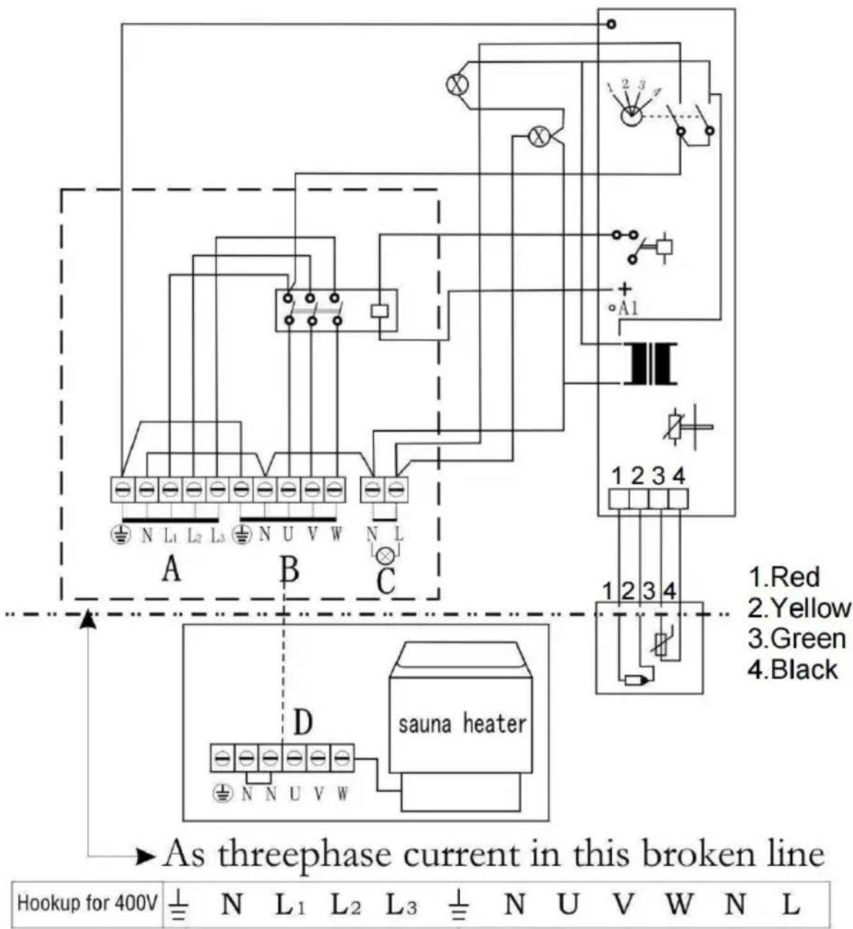
A. Power input(400V 50/60Hz)
B. Power output
C. Power input of sauna light(220V,<40W)
D. Power input of sauna heater
FIG7
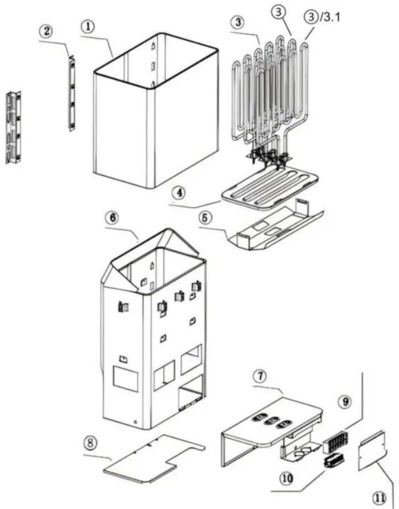
Product breakdown diagram

| Item | Name | QTY |
| 1 | Body cover | 1 |
| 2 | Wall mounting rack | 1 |
| 3 | Heating element | 3 |
| 4 | SCA stone holder | 1 |
| 5 | SCA mid reflection sheet | 1 |
| 6 | Body | 1 |
| 7 | Heating element holder | 1 |
| 8 | Bottom cover | 1 |
| 9 | Connector | 1 |
| 10 | Cable clamp | 1 |
| 11 | Techplate | 1 |
| SCA-90W Heating element | ||
| 3 | 3kW Heating element | 2 |
| 3.1 | 2760W Heating element | 1 |
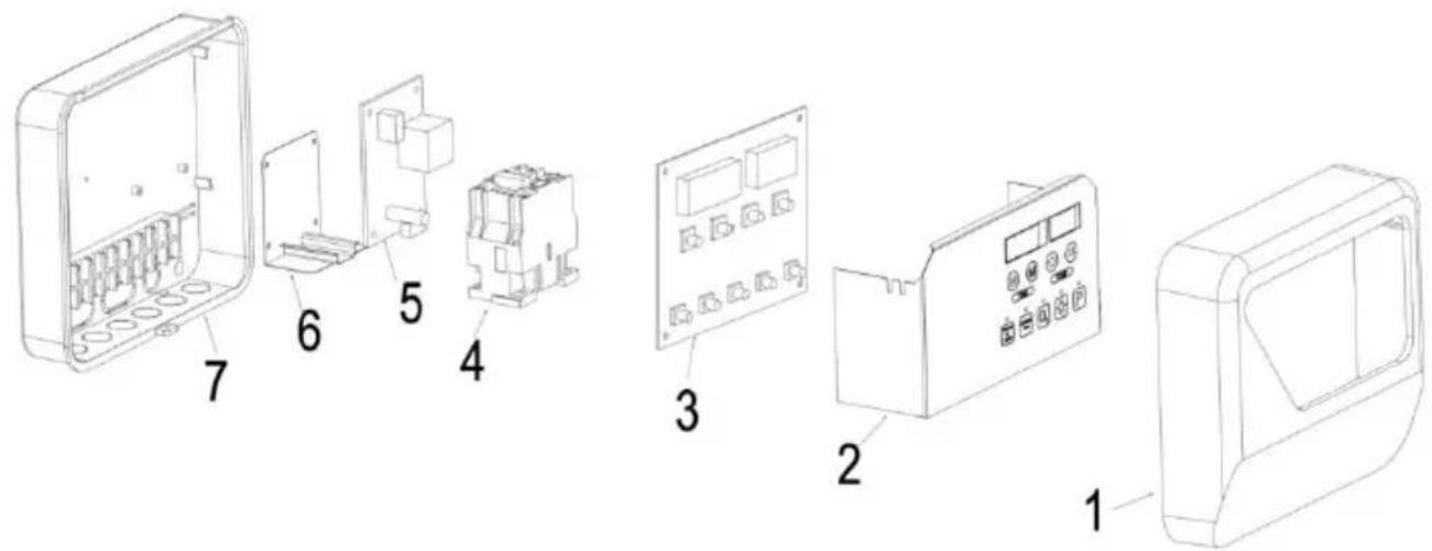
Controller block diagram
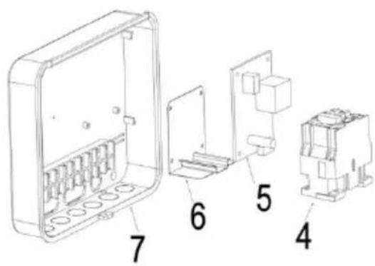
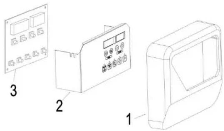
| Item | Name | QTY |
| 1 | Front cover | 1 |
| 2 | Display and control panel | 1 |
| 3 | Display circuit board | 1 |
| 4 | AC Contactor | 1 |
| 5 | Controller circuit board | 1 |
| 6 | Steel holder for AC Contact | 1 |
| 7 | Bottom cover | 1 |
Manufacturer: Shanghaimuxinmuyeyouxiangongsi
Address: Shuangchenglu 803nong11hao1602A-1609shi, baoshanqu, shanghai 200000 CN.
Imported to AUS: SIHAO PTY LTD. 1 ROKEVA STREETEASTWOOD NSW 2122 Australia
Imported to USA: Sanven Technology Ltd. Suite 250, 9166 Anaheim Place, Rancho Cucamonga, CA 91730
| UK | REP |
YH CONSULTING LIMITED. C/O YH Consultin Limited Office 147, Centurion House, London Road, Staines-upon-Thames, Surrey, TW18 4A>
| EC | REP |
Technical Support and E-Warranty Certificate www.vevor.com/support
VEVOR®
TOUGH TOOLS, HALF PRICE
natural_image
Line drawing of a portable air conditioner unit and its control panel (no text or symbols)BESOIN D'AIDE ? CONTACTEZ-NOUS !
Fig3

Fig4
| Chauffage | Distance (mm) | ||
| UN | C | D | |
| 3 kW | 50 | 280 | 80 |
| 4,5 kW | 80 | 280 | 100 |
| 6 kW | 100 | 280 | 150 |
| 8 kW | 130 | 300 | 200 |
| 9 kW | 130 | 300 | 200 |
natural_image
Pure electrical circuit lines without any symbolsCONTRÔLE DE LIMITE
natural_image
Diagram of a room layout with lighting fixtures and a 260Min indicator (no text or symbols beyond basic labels)Fig5

Fig6
FONCTIONNEMENT DU PANNEAU DE COMMANDE (APRÈS LA MISE SOUS TENSION)
A. Power input(400V 50/60Hz)
B. Power output
C. Power input of sauna light(220V, <40W)
D. Power input of sauna heater
FIG7
Lieu, Rancho Cucamonga, CA 91730
| UK | REP |
YH CONSULTING LIMITED. C/O YH Consultin Limited Office 147, Centurion House, London Road, Staines-upon-Thames, Surrey, TW18 4A>
| EC | REP |
natural_image
Line drawing of a portable air conditioner unit and its control panel (no text or symbols)Abb. 3

Abb. 4
| Heizung | Abstand (mm) | ||
| A | C | D | |
| 3 kW | 50 | 280 | 80 |
| 4,5 kW | 80 | 280 | 100 |
| 6 kW | 100 | 280 | 150 |
| 8 kW | 130 | 300 | 200 |
| 9 kW | 130 | 300 | 200 |
natural_image
Pure electrical circuit lines without any symbolsnatural_image
Diagram of a device emitting exhaust lines, showing components like a fan, detector, and control unit (no text labels)Fig5

Fig6
A. Power input(400V 50/60Hz)
B. Power output
C. Power input of sauna light(220V, <40W)
D. Power input of sauna heater
Abb. 7
YH CONSULTING LIMITED. C/O YH Consultin Limited Office 147, Centurion House, London Road, Staines-upon-Thames, Surrey, TW18 4A>
| EC | REP |
natural_image
Line drawing of a portable air conditioner unit and its control panel (no text or symbols)Figura 3
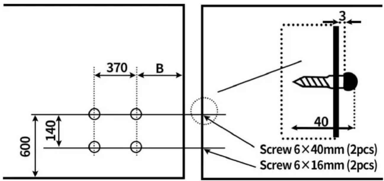
Figura 4
| Stufa | Distanza (mm) | ||
| UN | C | D | |
| 3 kW | 50 | 280 | 80 |
| 4,5 kW | 80 | 280 | 100 |
| 6 kW | 100 | 280 | 150 |
| 8 kW | 130 | 300 | 200 |
| 9 kW | 130 | 300 | 200 |
| Modello | SCA-30 W | SCA 45 W | SCA-6 0W | SCA 8 0W | SCA 9 0W | ||
| Energia | KW | 3.0 | 4.5 | 6 | 8.0 | 9.0 | |
| Stanza della sauna | Volume ( m3 ) | Minimo | 2 | 3 | 5 | 8 | 9 |
| Massimo | 4 | 6 | 9 | 12 | 13 | ||
| Altezza minima (cm) | 190 | 190 | 190 | 190 | 190 | ||
| Distanza minima dal riscaldata tore a | lato e parete posteriore min. ( cm) | 5 | 8 | 10 | 13 | 13 | |
| Se 500 mm olt il parapetto del pavimento min. (cm) | 5 | 8 | 15 | 20 | 20 | ||
| Soffitto min.(cm) | 110 | 110 | 110 | 110 | 110 | ||
| Pavimento Min.(cm) | 18 | 18 | 18 | 18 | 18 | ||
| Cavi a | 400 V (mm2) | 1.5 | 1.5 | 1.5 | 2.5 | 2.5 | |
natural_image
Pure electrical circuit lines without any symbolsCONTROLLO DEI LIMITI
natural_image
Diagram of a room layout with lighting fixtures and a 260Min indicator (no text or symbols beyond basic labels)Fig5

Fig6
A. Power input(400V 50/60Hz)
B. Power output
C. Power input of sauna light(220V, <40W)
D. Power input of sauna heater
FIG7
YH CONSULTING LIMITED. C/O YH Consultin Limited Office 147, Centurion House, London Road, Staines-upon-Thames, Surrey, TW18 4A>
| EC | REP |
natural_image
Line drawing of a portable air conditioner unit and its control panel (no text or symbols)Figura 3

Figura 4
| Calentador | Distancia (mm) | ||
| A | do | D | |
| 3 kW | 50 | 280 | 80 |
| 4,5 kW | 80 | 280 | 100 |
| 6 kW | 100 | 280 | 150 |
| 8 kW | 130 | 300 | 200 |
| 9 kW | 130 | 300 | 200 |
| Modelo | SCA-30 W | SCA 45 W | SCA-6 0W | SCA 8 0W | SCA 9 0W | ||
| Fuerza | KW | 3.0 | 4.5 | 6 | 8.0 | 9.0 | |
| Sala de sauna | Volume n ( m3 ) | Mínimo | 2 | 3 | 5 | 8 | 9 |
| Máximo o | 4 | 6 | 9 | 12 | 13 | ||
| Altura mín.(cm) | 190 | 190 | 190 | 190 | 190 | ||
| Distancia mínima del calenta dor a | Pared lateral y trasera mín . (cm) | 5 | 8 | 10 | 13 | 13 | |
| Si hay más de 500 mm desde barandilla del suelo, mín. (cm) | 5 | 8 | 15 | 20 | 20 | ||
| Techo mín.(cm) | 110 | 110 | 110 | 110 | 110 | ||
| Piso Mín.(cm) | 18 | 18 | 18 | 18 | 18 | ||
| Cables a | 400 V (mm2) | 1.5 | 1.5 | 1.5 | 2.5 | 2.5 | |
natural_image
Pure electrical circuit lines without any symbolsCONTROL DE LÍMITES
natural_image
Diagram of a room layout with lighting fixtures and a 260Min indicator (no text or symbols beyond basic labels)Fig5
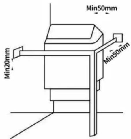
Fig6
FUNCIONAMIENTO DEL PANEL DE CONTROL (DESPUÉS DEL ENCENDIDO)
A. Power input(400V 50/60Hz)
B. Power output
C. Power input of sauna light(220V, <40W)
D. Power input of sauna heater
FIG7
YH CONSULTING LIMITED. C/O YH Consultin Limited Office 147, Centurion House, London Road, Staines-upon-Thames, Surrey, TW18 4A>
| EC | REP |
natural_image
Line drawing of a portable air conditioner unit and its control panel (no text or symbols)POTRZEBUJESZ POMOCY? SKONTAKTUJ SIĘ Z NAMI!
Rys. 3

Rys. 4
natural_image
Pure electrical circuit lines without any symbolsFig6
OBSŁUGA PANELU STEROWANIA (PO WŁĄCZENIU ZASILANIA)
A. Power input(400V 50/60Hz)
B. Power output
C. Power input of sauna light(220V, <40W)
D. Power input of sauna heater
FIG7
YH CONSULTING LIMITED. C/O YH Consultin Limited Office 147, Centurion House, London Road, Staines-upon-Thames, Surrey, TW18 4A>
| EC | REP |
natural_image
Line drawing of a portable air conditioner unit and its control panel (no text or symbols)HULP NODIG? NEEM CONTACT MET ONS OP!
Figuur 3

Figuur 4
| Verwarming | Afstand (mm) | ||
| A | C | D | |
| 3 kW | 50 | 280 | 80 |
| 4,5 kW | 80 | 280 | 100 |
| 6 kW | 100 | 280 | 150 |
| 8 kW | 130 | 300 | 200 |
| 9 kW | 130 | 300 | 200 |
| Model | SCA-30 W | SCA45 W | SCA-60W | SCA 80W | SCA90W | ||
| Stroom | KW | 3.0 | 4.5 | 6 | 8.0 | 9.0 | |
| Saunar uimte | Volume ( m3 ) | Min | 2 | 3 | 5 | 8 | 9 |
| Maximaal | 4 | 6 | 9 | 12 | 13 | ||
| Hoogte min. (cm) | 190 | 190 | 190 | 190 | 190 | ||
| Minimal e afstand van verwarming tot | zij- en achterkar breedte min . (cm) | 5 | 8 | 10 | 13 | 13 | |
| Indien 500mm boven de vloergeleiderail min.(cm) | 5 | 8 | 15 | 20 | 20 | ||
| Plafond min.(cm) | 110 | 110 | 110 | 110 | 110 | ||
| Vloer Min.(cm) | 18 | 18 | 18 | 18 | 18 | ||
| Kabels naar | 400V (mm2) | 1,5 | 1,5 | 1,5 | 2,5 | 2,5 | |
natural_image
Pure electrical circuit lines without any symbolsBEPERKTE CONTROLE
natural_image
Diagram of a spray gun system with no visible text or symbolsFig5
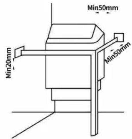
Fig6
BEDIENING VAN HET BEDIENINGSPANEEL (NA HET INSCHAKELEN)
A. Power input(400V 50/60Hz)
B. Power output
C. Power input of sauna light(220V, <40W)
D. Power input of sauna heater
FIG7
Productdecompositiediagram
| Item | Naam | AANTAL |
| 1 | Lichaamsbedekking | 1 |
| 2 | Wandmontagerek | 1 |
| 3 | Verwarmingselement | 3 |
| 4 | SCA-steenhouder | 1 |
| 5 | SCA middenreflectieblad | 1 |
| 6 | Lichaam | 1 |
| 7 | Verwarmingselementhouder | 1 |
| 8 | Onderkant deksel | 1 |
| 9 | Verbindingsstuk | 1 |
| 10 | Kabelklem | 1 |
| 11 | Techplate | 1 |
| SCA-90 W Verwarmingselement | ||
| 3 | 3kW verwarmingselement | 2 |
| 3.1 | 2760W Verwarmingselement | 1 |
Controller blokschema
YH CONSULTING LIMITED. C/O YH Consultin Limited Office 147, Centurion House, London Road, Staines-upon-Thames, Surrey, TW18 4A>
| EC | REP |
natural_image
Line drawing of a portable air conditioner unit and its control panel (no text or symbols)BEHÖVER DU HJÄLP? KONTAKTA OSS!
| Modell | SCA-60W | SCA-80W | SCA-90W |
| Spänning | 400V 3N~ | 400V 3N~ | 400V 3N~ |
| 50/60Hz | 50/60Hz | 50/60Hz | |
| Driva | 6 kW | 8 kW | 9 kW |
| Temperaturintervall | 35–110 °C | 35–110 °C | 35–110 °C |
| Tillämpligt utrymme | 176,5–317,8 fot^3 | 282,5–423,7 fot^3 | 317,8–459 fot^3 |
DELLISTA
Bild 3
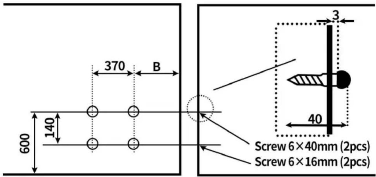
Bild 4
| Värmare | Avstånd (mm) | ||
| En | C | D | |
| 3 kW | 50 | 280 | 80 |
| 4,5 kW | 80 | 280 | 100 |
| 6 kW | 100 | 280 | 150 |
| 8 kW | 130 | 300 | 200 |
| 9 kW | 130 | 300 | 200 |
natural_image
Pure electrical circuit lines without any symbolsGRÄNSKONTROLL
natural_image
Pure diagram of a room layout with no text, numbers, or symbolsFig5

Fig6
ANVÄNDNING AV KONTROLLPANELEN (EFTER STRÖM PÅSLAGNING)
A. Power input(400V 50/60Hz)
B. Power output
C. Power input of sauna light(220V, <40W)
D. Power input of sauna heater
YH CONSULTING LIMITED. C/O YH Consultin Limited Office 147, Centurion House, London Road, Staines-upon-Thames, Surrey, TW18 4A>
| EC | REP |
www.vevor.com/support