
DG-K70 - Heating Vevor - Free user manual and instructions
Find the device manual for free DG-K70 Vevor in PDF.
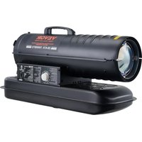


| Product type | Direct-fired forced air heater (diesel) |
| Model | DG-K70 |
| Brand | Vevor |
| Heat output | 20 kW |
| Fuel consumption | 1.9 L/h |
| Tank capacity | 19 L |
| Pump pressure | 31 kPa (4.5 psi) |
| Power supply | 220-240 V ~ 50 Hz, single phase |
| Fuel type | Diesel #1/#2 or kerosene 1-K |
| Ventilation required | Fresh air opening of at least 2,800 cm² per 29 kW/h |
| Thermal protection | Safety thermostat (shutdown at 80°C, reset at 80°C) |
| Electrical protection | Circuit breaker and fuse on electronic board |
| Ignition system | Spark ignition (spark plug) |
| Flame detection | Photoelectric cell |
| Dimensions (approx.) | Height: 55 cm, Width: 30 cm, Depth: 45 cm |
| Weight (approx.) | 18 kg |
| Spare parts | Available from Vevor (full list in the manual) |
| Maintenance | Regular cleaning of filters, nozzle, tank, etc. (see manual) |
| Safety | Do not use in unventilated spaces, keep away from combustibles, unplug before maintenance |
Frequently Asked Questions - DG-K70 Vevor
User questions about DG-K70 Vevor
0 question about this device. Answer the ones you know or ask your own.
Ask a new question about this device
Download the instructions for your Heating in PDF format for free! Find your manual DG-K70 - Vevor and take your electronic device back in hand. On this page are published all the documents necessary for the use of your device. DG-K70 by Vevor.
USER MANUAL DG-K70 Vevor
KEROSENE HEATER
MODEL: DG-K70/DG-K100
VEVOR
KEROSENE HEATER
MODEL: DG-K70/DG-K100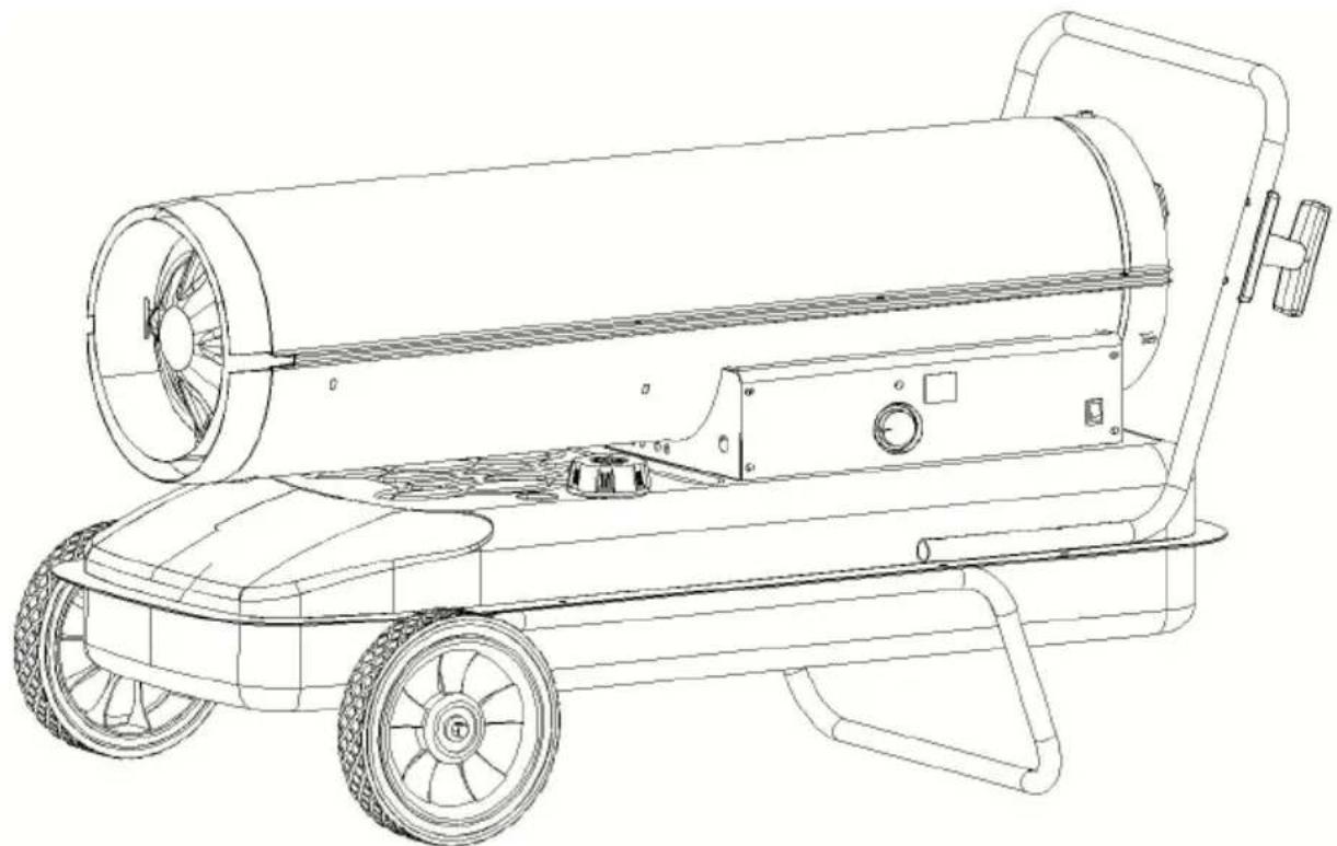
This is the original instruction. Please read all manual instructions carefully before operating. VEVOR reserves a clear interpretation of the user manual. The appearance of the product shall be subject to the product you received. Please forgive us that we won't inform you again if there are any technology or software updates on our product.
CONSUMER: Retain this manual for future reference.
IMPORTANT: Read and understand all of the directions in this manual before assembling, starting, or servicing the heater. Improper use of this heater can cause serious injury. Keep this manual for reference. Not suitable for use on wood floors or other combustible materials.
▲ DANGER GENERAL HAZARD WARNING:
Be sure to comply with the instructions and warnings provided by the heater, or death, serious bodily injury and property loss, or damage from the hazards of fire, explosion, burn, asphyxiation, and carbon monoxide poisoning can result.
Only people who understand these instructions should use or service the heater.
If you need heater information such as an instruction manual, contact the dealer or manufacturer.
▲ DANGER NOT FOR USE IN NON-ADEQUATELY VENTILATED ENCLOSED SPACES.
⚠ WARNING: NEVER LEAVE THE HEATER UNATTENDED WHILE BURNING OR WHILE CONNECTED TO A POWER SOURCE.
⚠ WARNING: Fire, burn, inhalation, and explosion hazard. Keep combustibles, such as building materials, paper, or cardboard, at a distance from the heater, as these instructions recommend. Never use the heater in spaces that contain products such as gasoline, paint thinners, dust particles, volatile or airborne combustibles, or unknown chemicals. This is an unvented portable heater. It uses oxygen from the area in which it is used. Adequate combustion and ventilation air must be provided. Refer to ventilation on Page 7.
WARNING
Do not operate this heater until you have read and
thoroughly understand these safety and operating instructions. Failure to comply with the precautions and instructions provided with this heater can result in death, serious bodily injury, property loss or damage, fire hazards, soot production, explosion, burns, asphyxiation, or carbon monoxide poisoning. Only persons who can read and understand the instructions should use or service this heater. Not for use in recreational vehicles.
WARNING
Electrical Safety: The owner is responsible for checking
this electrical product before use to ensure it is safe. You must check power cables, plugs, sockets, etc., for signs of wear or damage. You must ensure that electric shock risk is minimized by installing appropriate safety devices. The main distribution board should incorporate a residual current circuit breaker (RCCB). We also recommend that a residual current device (RCD) be used. This is particularly important for mobile devices that are connected without an RCCB. Any fault rectification or electrical work, including connection of a plug, must be carried out by a qualified electrician. You must also comply with electrical safety requirements, including the Electricity at Work Act 1989, which requires portable electrical appliances used on business premises to be PAT tested annually.
The Health & Safety at Work Act 1974 places responsibility for the condition of electrical appliances upon owners. Power cables and plugs should always be regularly inspected for safety. If in doubt about electrical safety, you must consult a qualified electrician.
Safety Information
▲ DANGER: Indicates an imminently hazardous situation which, if not avoided, WILL result in death or serious injury.
▲ WARNING: Indicates a potentially hazardous situation which, if
not avoided, COULD result in death or serious injury.
▲ CAUTION: Indicates a potentially hazardous situation which, if
not avoided, MAY result in minor or moderate injury.
This is a Diesel (or Kerosene) (No. 1/Diesel or 1-K Kerosene) directed-forced air heater. It is primarily intended for temporarily heating buildings under construction, alteration, or repair. Directed-fired means that all of the combustion products of the heater enter the heated space. This appliance is rated at 98% combustion efficiency but does produce a small amount of carbon monoxide. Carbon monoxide is toxic.
▲ DANGER: Carbon monoxide poisoning may lead to death!
Humans can tolerate small amounts of carbon monoxide, and precautions should be taken to provide proper ventilation. According to this manual, failure to provide proper ventilation can result in death. Early signs of carbon monoxide poisoning resemble the flu. Symptoms of improper ventilation are:
* Headache * dizziness * burning of the nose and eyes * nausea * dry mouth * sore throat *
For optimal performance of this heater, it is strongly suggested that 1-K kerosene be used. 1-K kerosene has been refined to virtually eliminate contaminants, such as sulfur, which can cause a rotten egg odor during the operation of the heater. However, #1 or #2 diesel may also be used if 1-K kerosene is not available. Be advised that these fuels are not as clean as 1-K kerosene, and care should be taken to provide more ventilation to accommodate any added contaminants that may be added to the heated space. Use of #1 or #2 diesel may result in more periodic maintenance.
⚠ WARNING: Risk of indoor air pollution!
- Use this heater only in well-ventilated areas! Provide at least a three-square-foot (2800 sq cm) outside air opening for every 29 kW/hr heater rating.
- Carbon Monoxide Poisoning. Early signs of carbon monoxide poisoning resemble flu-like symptoms such as headaches, dizziness, and/or nausea. If you have these symptoms, your heater may not be working properly. - Get fresh air at once! Have the heater serviced. Some people are more affected by carbon monoxide than others. These include pregnant women
those with heart or lung problems, anemia, or those under the influence of alcohol or at high altitudes.
⚠ WARNING: Risk of burns / fire / explosion!
- NEVER use fuels such as gasoline, benzene, paint thinners, or other compounds in this heater (RISK OF FIRE OR EXPLOSION).
- NEVER refill the heater's fuel tank while the heater is operating or hot. This heater is EXTREMELY HOT while in operation.
- Keep all combustible materials away from this heater.
- NEVER block the air inlet or air outlet of the heater.
- NEVER use ductwork in front or at the rear of the heater.
-NEVER move or handle the heater while still hot.
-NEVER transport a heater with fuel in its tank.
-If equipped with a thermostat, the heater may start anytime.
-ALWAYS locate the heater on a stable and level surface.
-ALWAYS keep children and animals away from the heater.
-Bulk fuel storage should be a minimum of 762cm from heaters, torch portable generators, or other ignition sources. All fuel storage should be in accordance with federal, state, or local authorities jurisdiction.
-NEVER use this heater in living or sleeping areas.
-NEVER use this heater where flammable vapors may be present.
⚠ WARNING Risk of electric shock!
-Use only the electrical power (Voltage and frequency) specified on the model plate of the heater. Use only a local correct plug, grounded outlet and extension cord.
-ALWAYS install the heater so that it is not directly exposed to water rain, dripping water, or wind.
-ALWAYS unplug the heater when not in use.
Minimum clearance from combustibles:
| Orientation | DG-K70 | DG-K100 |
| Top(cm) | 125 | 125 |
| Side(cm) | 125 | 125 |
| Front(cm) | 250 | 250 |
Features
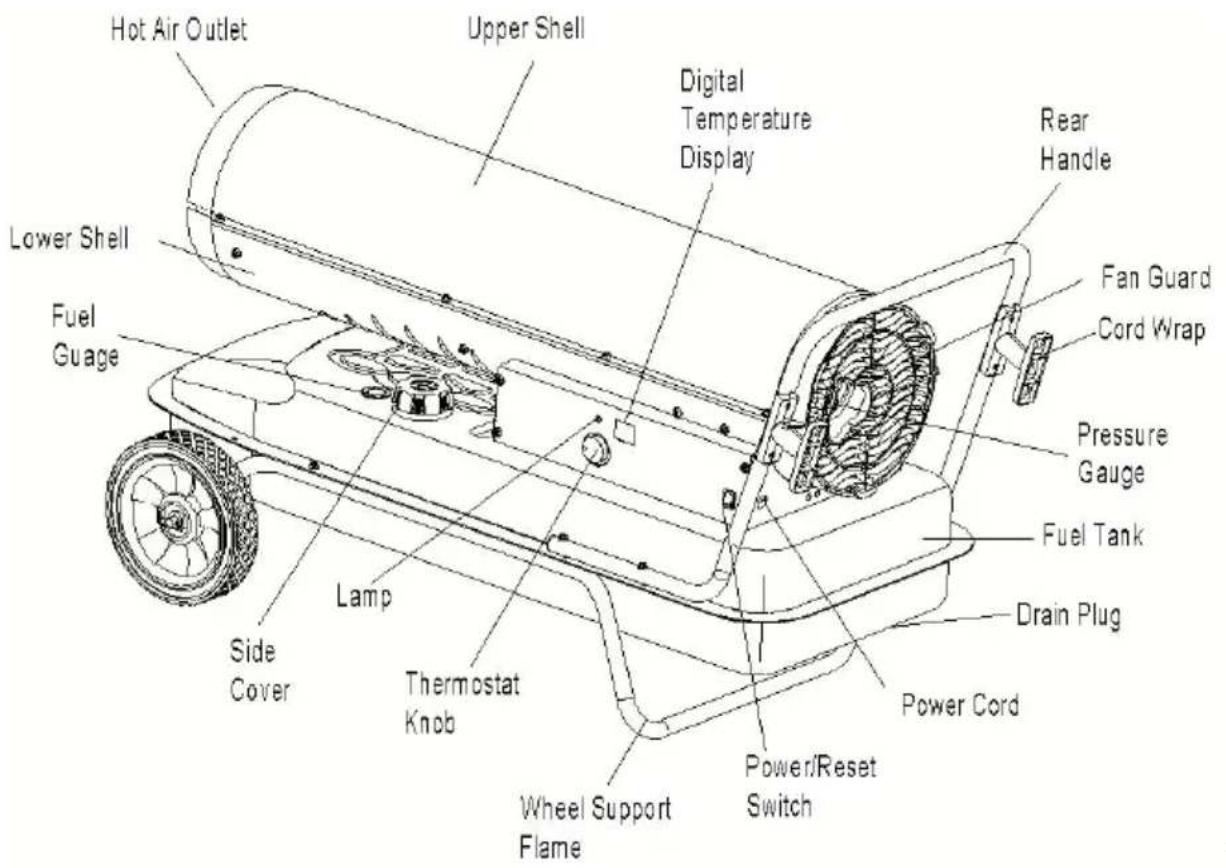
Fig.1
Specifications
| Model | DG-K70 | DG-K100 |
| Heat Output (kW) | 20 | 30 |
| Fuel Consumption (L/Hr) | 1.9 | 2.9 |
| Fuel Tank Capacity (L) | 19 | 38 |
| Pump Pressure(kpa/psi) | 31/4.5 | 34.5/5 |
| Power Supply(V/Hz/A) | 220-240/50/5 | 220-240/50/5 |
| Phase | single | single |
Specifications subject to change without notice.
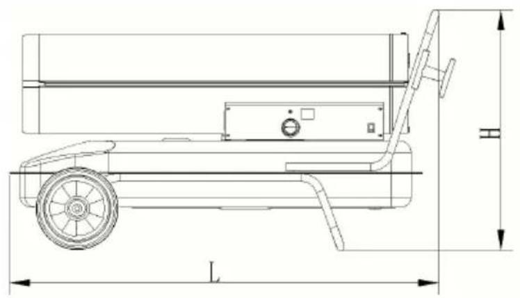
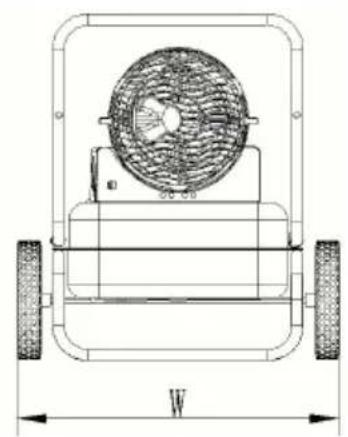
Fig. 2
| Model | DG-K70 | DG-K100 |
| L(mm) | 870 | 915 |
| W(mm) | 385 | 475 |
| H(mm) | 550 | 490 |
Unpacking
Remove the heater and all of the packing materials from the shipping carton.
NOTE: Save the box and packing materials for future storage.
Check the chart below to ensure you have all the parts required to assemble your heater.
Assembly
| No. | Specifications | Picture | QTY |
| 1 | Wheel support frame | 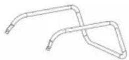 | 1pcs |
| 2 | Rear Handle | 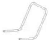 | 1pcs |
| 3 | Wheel | 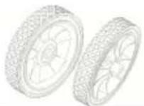 | 2pcs |
| 4 | Axle | 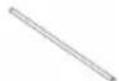 | 1pcs |
| 5 | Cotter Pin | 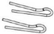 | 2pcs |
| 6 | Cord Wrap | 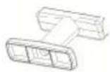 | 2pcs |
| 7 | Screw (M5*42) | 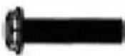 | 2pcs |
| 8 | Screw(M5*28) |  | 8pcs |
| 9 | Nut(M5) |  | 10pcs |
| 10 | Washer |  | 2pcs |
| 11 | Manual | 1pcs |
Tool preparation
Tools required: Medium Phillips screwdriver, 5/16" open end or adjustable wrench, needle nose pliers.
ASSEMBLING FRAME AND WHEELS
1. Slide the axle through holes in the wheel support frame. 2. Slide wheels onto each axle, ensuring that the valve stem (if present) is to the outside (see Fig. 2). 3. Slide flat washers (L) onto the axle past the small hole. Insert the pin in the axle hole and bend the pin's legs with needle nose pliers to secure. 4. Place the heater on the assembled frame, ensuring that the air inlet is by the wheels and that the mounting holes on the tank flange of the heater align with the holes in the frame. 5. Take the rear handle, align the mounting holes with the corresponding
holes in the tank flange/wheel frame, slide a screw through the holes and loosely attach a nut. Repeat for the other 2 holes, then fully tighten screws and nuts.
CAUTION
Do not operate heater without support frame fully assembled to tank.
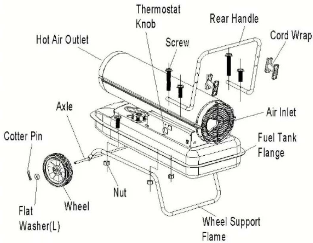
Fig. 3
Operation
Diesel (or 1-K Kerosene)
For optimal performance of this heater, it is strongly suggested that 1-K kerosene be used. 1-K kerosene has been refined to virtually eliminate contaminants, such as sulfur, which can cause a rotten egg odor during operation of the heater. However, #1 or #2 Diesel may also be used if kerosene is not available. Be advised that these fuels do not burn as cleanly as 1-K kerosene, and care should be taken to provide more fresh air ventilation to accommodate any added contaminants that may be introduced into the heated space. Using diesel fuel can cause excess soot production.
DO NOT use any fuel that is not approved above.
NOTE: Diesel (1-K Kerosene) should only be stored in a blue container that is clearly marked “Diesel (1-K Kerosene)”. Never store Diesel (1-K Kerosene) in a red container. Red is associated with gasoline.
- NEVER store Diesel (1-K Kerosene) in the living space. Diesel (1-K Kerosene) should be stored in a well-ventilated area outside the living area.
- NEVER use fuel such as gasoline, benzene, alcohol, white gas, camp stove fuel, paint thinners, or other oil compounds in this heater (THESE ARE VOLATILE FUELS THAT CAN CAUSE A FIRE OR EXPLOSION).
- NEVER store Diesel (1-K Kerosene) in direct sunlight or near a source of heat.
- NEVER use Diesel (1-K Kerosene) that has been stored from one season to the next. It deteriorates over time.
OLD Diesel (1-K Kerosene) WILL NOT BURN PROPERLY IN THIS HEATER.
- Use diesel in the heater. 1-K Kerosene is a suitable substitute.
THEORY OF OPERATION
Fuel System: This heater is equipped with an air pump that operates off the electric motor. The pump forces air through the air line that connects to the fuel tank, drawing fuel to the nozzle in the burner head. Air also passes through the nozzle where it mixes with the fuel and is sprayed into the combustion chamber in a fine mist.
Quick-Fire Ignition: A transformer sends high voltage to a two-prong spark plug. The spark ignites the fuel/air mixture as it is sprayed into the combustion chamber.
Air System: A fan is turned by the heavy-duty motor, which forces air into the combustion chamber, where it is super-heated and forced out the front of the chamber.
Temperature Limit Control: This heater is equipped with a temperature limit control designed to turn it off should the internal temperature rise to an unsafe level. If this device activates and turns your heater off, it may
require service.
You can start your heater once the temperature falls below the reset temperature.
| MODELS | Internal Shut-Off Temp. Plus/Minus 10 Degrees | Reset Temperature Plus/Minus 10 Degrees |
| DG-K70 | 176°F/80°C | 176°F/80°C |
| DG-K100 | 176°F/80°C | 176°F/80°C |


Fig.4 Temperature control switch
Electrical System Protection: The heater's electrical system is protected by a circuit breaker that protects the system components from damage. If the heater fails, check the fuse first and replace it if necessary.
| FUSE TYPE: | DG-K70/DG-K100 | KSD |
Flame Sensor: The heater uses a photocell to see the flame in the combustion chamber. Should the flame extinguish, the sensor will stop electrical current, and the heater will shut off.
FUELING THE HEATER
| ⚠CAUTION NEVER FILL THE FUEL TANK INDOORS. ALWAYFILL FUEL TAHNK OUTDOORS.BE SURE THE HEATER IS ON LEVEL GROUND WHEN FUELIAND NEVER OVERFILL THE FUEL TANK. |
| ⚠WARNING NEVER FILL THE FUEL TANK INDOORS. ALWAYFILL FUEL TAHNK OUTDOORS.BE SURE THE HEATER IS ON LEVEL GROUND WHEN FUELIAND NEVER OVERFILL THE FUEL TANK. |
It is always a good idea to fire the heater outdoors for the first time to allow any oils used in the manufacturing process to be burned off in the environment. This initial burn should last at least 10 minutes.
VENTILATION
Risk of indoor air pollution. Use heater only in well-ventilated areas. Always provide a fresh air opening in the heated space of at least 1 square foot (2800 sq. cm) for each 29 kW/hr of heater output. Provide a larger opening if more heaters are required.
-a two-car garage door raised 15.24 cm (6 inches)
-a single-car garage door raised 22.86 cm (9 inches)
-TWO, 76.2 cm (30 inches) windows raised 38.1 cm (15 inches)
TO START THE HEATER
- Fill the tank with Diesel (1-K Kerosene) until the fuel gauge points to the desired level.
- Ensure the fuel cap is secure.
- Plug the power cord into the correct local outlet. Use a grounded extension cord and plug it into a three-prong 220-240VAC grounded outlet. The extension cord should be at least six feet (1.8 meters) long.
Extension cord wire size requirements are as follows:
- For 6 to 10 feet (1.8 to 3 meters), use 18 AWG wire. - For 11 to 100 feet (3.4 to 30.4 meters), use 16 AWG wire. - For 101 to 200 feet (30.8 to 61 meters), use 14 AWG wire. 4. Turn the thermostat control knob to the desired temperature setting. The setting range is from 40°F to 110°F. Push the power switch to the ON position (Fig.5). The power indicator lamp and room temperature display (DG-K100 only) will light, and the heater will start.
NOTE: The room temperature display (DG-K100 only) will indicate the following:
- When the room temperature is less than 0°F, the display will show 'LO'. The thermostat may be set too low if the heater does not fire. Turn the control knob to a higher setting until the heater fires; if the heater does not start, push the power switch to 'OFF', then back to 'ON'. If the
heater still does not fire, see the Troubleshooting Guide on page 18.
NOTE: The electrical components of this heater are protected by a fuse mounted on the PC board. If the heater fails to fire, check the fuse and replace it if necessary. Also, check the power source to ensure voltage is being provided to the heater.
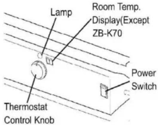
Fig.5. Control panel for all models
TO STOP THE HEATER
Simply turn the power switch to the 'OFF' position and unplug the power cord.
TO RESTART THE HEATER
- Wait 10 seconds after shutting off the heater.
- Turn the power switch to the 'ON' position.
- Be sure to follow all starting procedure precautions.
ELECTRICAL OUTLET
▲WARNING Shock Hazard!
- Never plug an appliance with more than a 5 amp rating into this outlet. - Always keep the outlet covered when not in use.
LONG TERM STORAGE
Drain Fuel Tank
- For models DG-K70, drain fuel through the fuel cap opening using an approved siphon. For models DG-K100, drain fuel through the drain at the bottom of the fuel tank.
- To remove the drain plug (DG-K100), pull the plug grip downward and remove the seal head from the drain hole in the tank (see Fig. 6).
- Using a small amount of Diesel (1-K Kerosene), rinse and swirl the Diesel (1-K Kerosene) inside the fuel tank. Empty the tank fully.
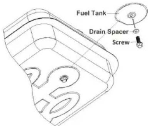
Fig. 6 Drain Plug Removal. Pump pressure adjustment. To replace, push the drain head fully into the drain hole and secure by pushing the seal cap fully into the head hole (see Fig. 7).
IMPORTANT: Never store leftover Diesel (1-K Kerosene) over the summer. Using old fuel can damage your heater.
Store heater in a dry, well-ventilated area.
Be sure that the storage area is free of dust and corrosive vapors. Keep the heater in the original shipping material. Keep the Users Manual in an easily accessible place.
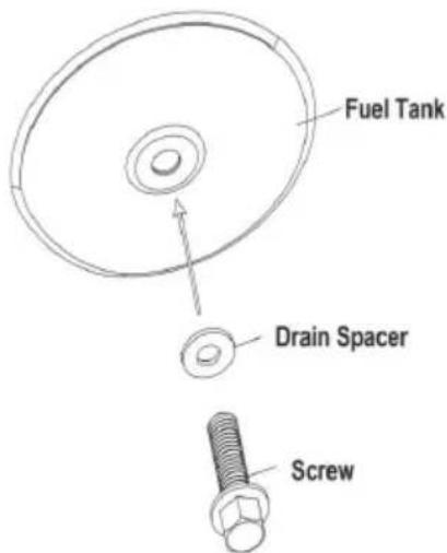
Fig.7 Drain Plug Reinstall
Maintenance
⚠ WARNING Never service heater while it is plugged in or while
Use only original equipment replacement parts. Using alternate or third-party components can cause unsafe operating conditions and will void your warranty.
We suggest following a maintenance schedule as follows:
FUEL/FUEL TANK
Flush every 200 hours of operation or as needed. Do not use water in the tank. Use fresh Diesel (1-K Kerosene) only.
AIR FILTERS:
The air intake filter should be replaced or washed with soap and water, and dried thoroughly every 500 hours of operation, or less, depending on conditions.
The output and lint filter should be replaced every 500 hours of operation or less, depending on conditions.
NOTE: Use of Diesel (1-K Kerosene) may require additional maintenance.
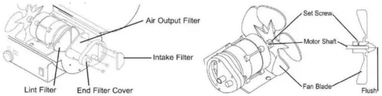
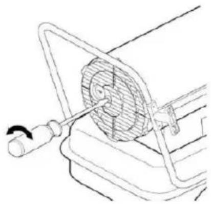
Fig.8 Filter Replacement Fig.9 Fan Replacement
FAN BLADES:
Blades should be cleaned at least once per heating season, depending on the condition. Remove all accumulated dust and dirt with a damp cloth without bending any of the fan blades. Be sure the fan blades are dry before re-starting the heater. For fan removal, see Fig.9
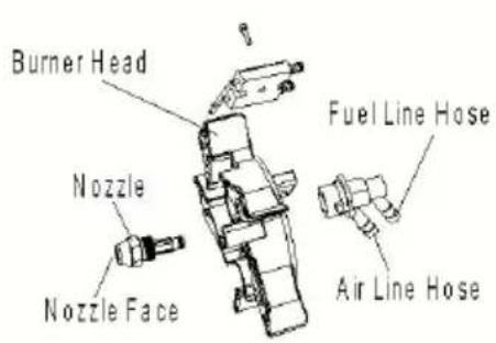
NOZZLES:
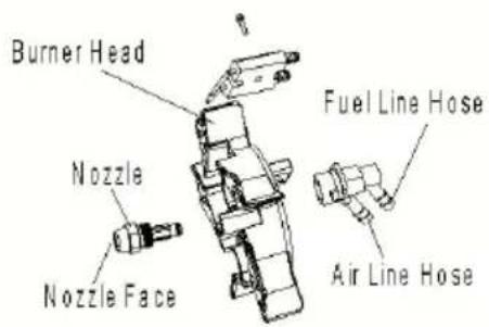
Nozzles should be cleaned or replaced at least once per heating season. Contaminated fuel could make this necessary immediately.
To clean dirt from the nozzle, blow compressed air through the nozzle.
It may be necessary to soak the nozzle in clean Diesel (1-K Kerosene) to help loosen any particles.
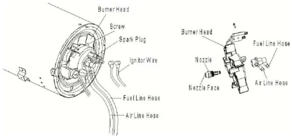
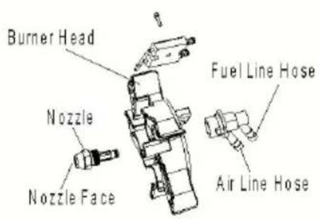
Fig.10 Nozzle Replacement
NOTE: The use of Diesel (1-K Kerosene) may require additional maintenance. Using this heater without proper maintenance or with contaminated or old fuel may lead to improper combustion and possible soot production.
BE SURE FUEL USED IS APPROVED
Clean and re-gap every 600 hours of operation or replace as needed. Remove the spark plug, clean the terminals with a wire brush. Re-gap terminals to 0.35 cm.
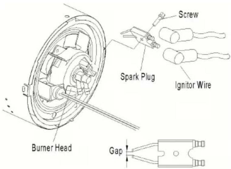
Fig.11 Spark plug replacement
PHOTOCELL:
The Photocell should be cleaned at least once per heating season or depending on the condition.
Use a cotton swab dipped in water or alcohol to clean the lens of the Photocell. Note the proper photocell position, as noted in Fig.12 and
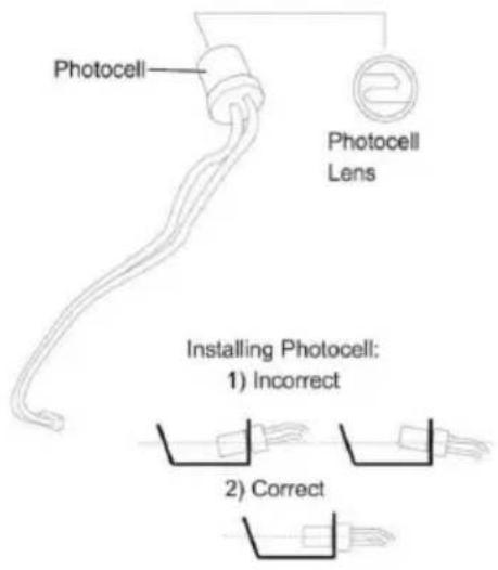
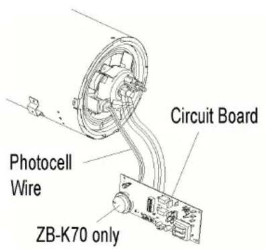
Fig.12 Photocell Positioning Fig.13 Photocell position for DG-K70
FUEL FILTER:
The fuel filter should be cleaned at least twice per heating season by rinsing it in clean Diesel (1-K Kerosene). Contaminated fuel could make this necessary immediately (See Fig.14).
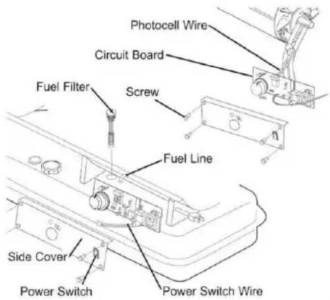
Fig.14 Fuel filter replacement
NOTE: Please draw out the rubber plug directly to remove the fuel filter.
all models. The use of diesel may require additional maintenance. Improper maintenance can lead to poor combustion and soot production.
PUMP PRESSURE ADJUSTMENT:
While the heater is operating, turn the relief valve clockwise to increase pressure, counterclockwise to decrease (see Fig.15). Use a flat-blade screwdriver to turn the valve. The correct pump pressure is as follows:
| Model# | Pump Pressure(kpa/psi) |
| DG-K70 | 31/4.5 |
| DG-K100 | 34.5/5 |
Tolerance ± 10%
- If the flame is dim, turn up the pressure.
- If the flame comes out of the incendiary cylinder, reduce the pressure. For the best pressure measurement, test with a full tank of fuel. Optimum pressure occurs when the nose cone is cherry red and the heater has extending flames.
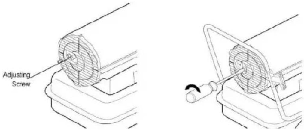
Fig.15. Pump pressure adjustment
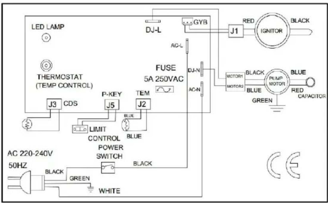
Wiring Diagrams
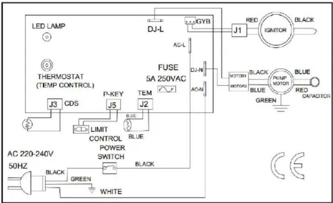
Fig.16 Model DG-K70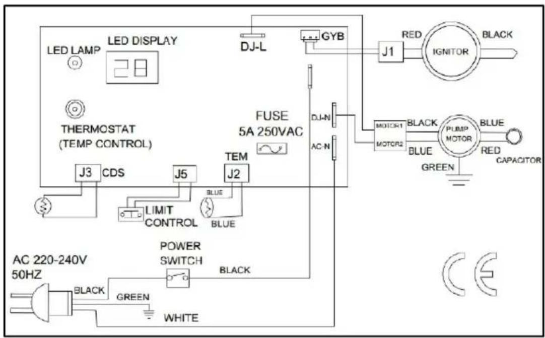
Fig.17 Models DG-K100
Troubleshooting Guide:
| Problem | Possible Cause | Solution |
| Switch on heaters, the machine doesn't start work, the | 1.Pump rotor or blad blocked2.Motor failure3.Motor connecting wire loose or fall off | 1.Adjust the clearance between the rotor and outer ring2.Replace the motor3.Check the motor |
| display show ambient temperature . For example:"15" ,it means 16 | 4.Control board failure5.Wind leaf is distorted and stuck6.Voltage below level7.Setting temperature is lower than ambient temperature | connecting wire 4.Replace the control board 5.Replace the wind leaf7.Adjust the Voltage Adjust the setting temperature higher than ambient temperature. |
| Heater will not operate, or motor runs for short time,Lamp flickers and LED display shows"E1"(1flash) | 1.No Diesel in fuel tank.2.Incorrect pump pressure.3.The connection between the fuel nozzle and air/fuel pipe is incorrect4.Dirty fuel filter.5.Dirty nozzle.6.Moisture in fuel/fuel tank.7.Ignitor wire not connected to spark plug.8.Carbon deposits on the ignition electrode9.Photocell break down10.Photocell connecting wire is loose or broken | 1.Fill tank with fresh Diesel2.Adjust pump pressure (page20)3.Adjust the connection of /fuel pipe4.Clean/replace fuel filter (page 18) 5.Clean/replace nozzle (page 16-17) 6.Rinse out fuel tank with clean fresh Diesel (page14-15)7.Inspect all electrical connection (see wiring diagrams page (19-20)8.Replace Ignitor page 179.Replace or inspect photocell10.Adjust the position of the photocell bracket and fire viewing hole |
| 1.Switch on heaters, the machine doesn't start work, the display shows "E2"2.The heater shutdown during normal | 1.Temperature sensor failure 2.Temperature sensor loose or fractured connections | 1.Replace the temperature sensor 2.Check temperature sensor connections or replace it |
| operation and display show "E2" (2flashes) | ||
| Lamp is flickering, and LED display shows “E3” (3flashes) | 1.Overheating protection thermostat damaged2.overheating protection thermostat cable loosen or brea3.machine internal temp rise too high, overheating protection switches on, shut down automatically. | 1.Replace thermostat2.Inspect or replace the connected cable3.Considering the machine's service life and safety self-protection, it is a norm phenomenon. Just restart it after cooling down |
| Poor combustion and / or exce soot production | 1.Dirty input output c lint filter 2.Dirty fuel filterPoor quality of fuel Pump pressure is to high or too low | 1.Clean/replace air filter (page 13) 2.Clean/replace fuel filter (page 13) 3.Be s fuel is not contaminated or old4.Use proper pressure (page14) |
| Heater does not turn on at the lamp Is not lit | 1.Temperature limit sensor has overheated2.No electrical power 3.Fuse blown4.Improper electrical connection between Temperature Limit Sensor and Circuit Board | 1.Push power switch to “O” and allow heater to cool for 10 minutes. Push switch be to “ON”2.Check power cord and extension cord to insure of proper connection, test pow supplyCheck/replace fuseInspect all electrical connection (see wiring diagrams page17) |
Exploded view:
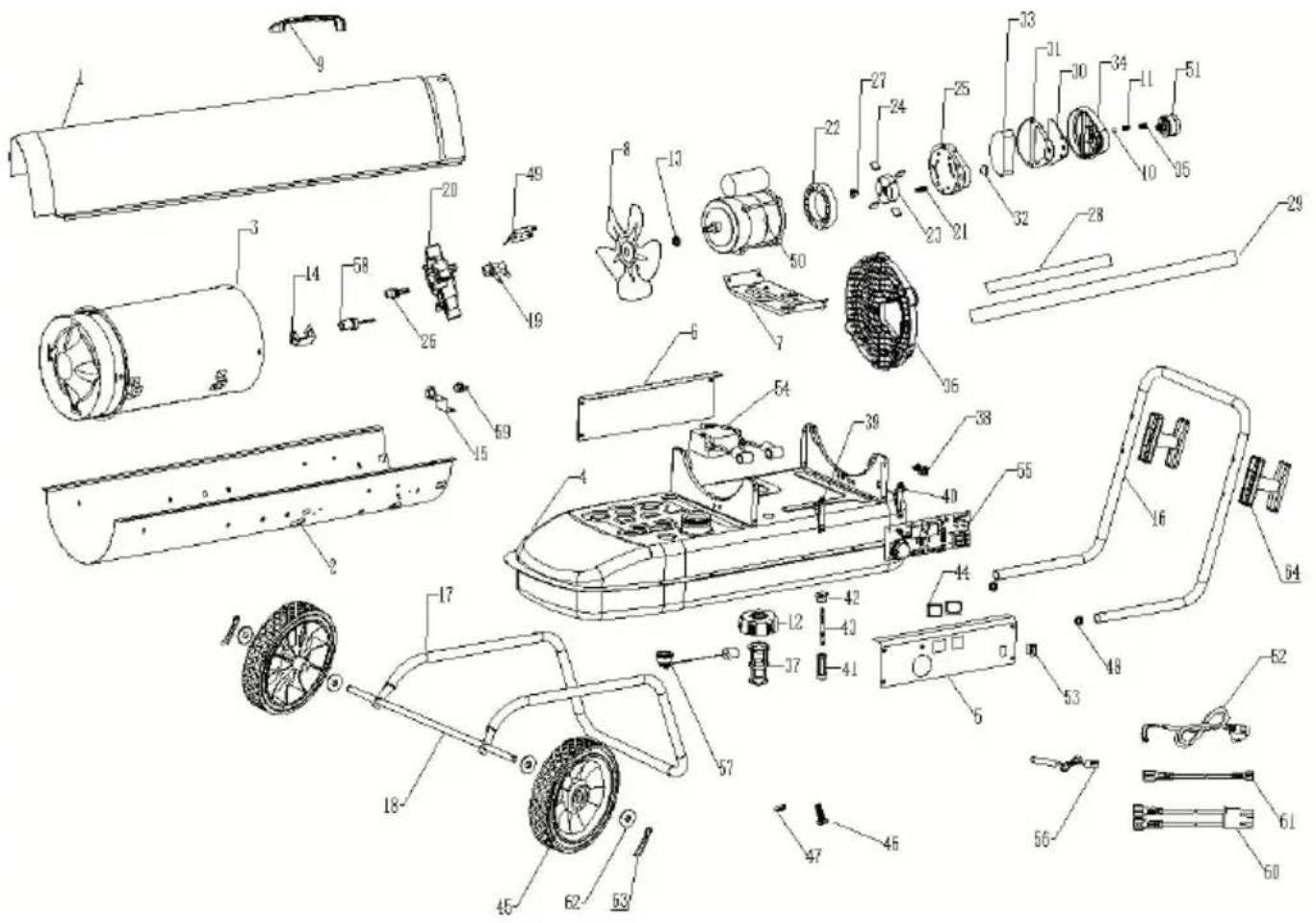
| NO# | Part Name | (PART CODE FOR MODEL) | Qty | |
| DG-K70 | DG-K100 | |||
| 1 | Up Shell | DG20-010000 | DG30-010000 | 1 |
| 2 | Lower Shell | DG20-020000 | DG30-020000 | 1 |
| 3 | combustion chamber Assembly | K70-030000 | K125-030000 | 1 |
| 4 | Fuel Tank Assembly | K45-040000 | K125-040000 | 1 |
| 5 | Left side cover | K70-050000 | K125-050000 | 1 |
| 6 | Right Side Cover | K45-060000 | K125-060000 | 1 |
| 7 | Motor mounting bracket | K45-100000 | K125-100000 | 1 |
| 8 | Fan assembly | K45-110000 | K125-110000 | 1 |
| 9 | Handle | G10-010000 | 1 | |
| 10 | Ball | K215-121200 | K215-121200 | 1 |
| 11 | spring | K45-121300 | K45-121300 | 1 |
| 12 | Fuel Cap | K45-140000 | K45-140000 | 1 |
| 13 | Fan blade Aluminum base | K45-110101 | K45-110101 | 1 |
| 14 | Photo Cell bracket | K45-230000 | K45-230000 | 1 |
| 15 | Thermostat bracket | K45-250100 | K45-250100 | 1 |
| 16 | Rear Handle | K125-300000 | 1 | |
| 17 | wheel support Frame | K125-310000 | 1 | |
| 18 | wheel Axle | K45-320001 | K125-320001 | 1 |
| 19 | Nozzle seat | K45-070101 | K45-070101 | 1 |
| 20 | Burner head | K45-070200 | K125-070200 | 1 |
| 21 | Nipple | K45-070400 | K45-070400 | 2 |
| 22 | Pump Body | K45-120200 | K100-120200 | 1 |
| 23 | Rotor Kit | K45-120400 | K100-120400 | 1 |
| 24 | Blade | K45-120500 | K100-120500 | 4 |
| 25 | End pump cover | K45-120600 | K45-120600 | 1 |
| 26 | Nozzle | K70-070100 | K100-070100 | 1 |
| 27 | rotor kit insert | K45-120300 | K45-120300 | 1 |
| 28 | Fuel Line | K70-080000 | K100-080000 | 1 |
| 29 | Air Line | K70-090000 | K100-090000 | 1 |
| 30 | output filter | K45-120700 | K45-120700 | 1 |
| 31 | Gasket outlet filter | K45-120800 | K45-120800 | 1 |
| 32 | lint filter | K45-120900 | K45-120900 | 1 |
| 33 | filter kit | K45-121000 | K45-121000 | 1 |
| 34 | End filter cover | K45-121100 | K45-121100 | 1 |
| 35 | Adjustment Screw | K45-121400 | K45-121400 | 1 |
| 36 | Fan Guard | K45-130000 | K125-130000 | 1 |
| 37 | Fuel filter #1 | K45-140100 | K45-140100 | 1 |
| 38 | Power Cord clip | K45-160000 | K45-160000 | 1 |
| 39 | Left PCB bracket | K45-190100 | K45-190100 | 1 |
| 40 | Right PCB bracket | K45-190200 | K45-190200 | 1 |
| 41 | Fuel Filter #2 | K45-220100 | K125-220100 | 1 |
| 42 | Seal sleeve | K45-220200 | K45-220200 | 1 |
| 43 | Fuel Filter #2 connecting pipe | K45-220300 | K125-220300 | 1 |
| 44 | windows display | K125-280000 | 1 | |
| 45 | wheel | K125-330001 | 2 | |
| 46 | Drain Screw | BG06002DBX | 1 | |
| 47 | Drain Spacer | K125-410000 | 1 | |
| 48 | handle plug | K125-390000 | 2 | |
| 49 | Spark plug kit | K45-070300 | K45-070300 | 1 |
| 50 | Motor | DG20-120100 | DG30-120100 | 1 |
| 51 | Air pressure Guage | K125-121500 | 1 | |
| 52 | Power cord | K45-150000 | K45-150000 | 1 |
| 53 | Power Switch | K45-170000 | K45-170000 | 1 |
| 54 | Ignitor | DG20-180000 | DG20-180000 | 1 |
| 55 | PCB | K70-200001 | K125-200100 | 1 |
| 56 | Temperature Sensor | K45-200120 | K45-200120 | 1 |
| 57 | Fuel Guage | K45-210000 | K125-210000 | 1 |
| 58 | Photo Cell | K45-240000 | K45-240000 | 1 |
| 59 | Thermostat | K45-250200 | K45-250200 | 1 |
| 60 | connecting line for Thermostat | K45-250300 | K45-250300 | 1 |
| 61 | connecting line for power cord | K45-290000 | K45-290000 | 1 |
| 62 | spacer | K125-350000 | 2 | |
| 63 | Split Pin | BG06001DBX | 2 | |
| 64 | Cord Wrap | K125-370000 | 2 | |

VEVOR
KEROSENE HEATER
MODEL: DG-K70/DG-K100
VEVOR
KEROSENE HEATER
MODEL: DG-K70/DG-K100
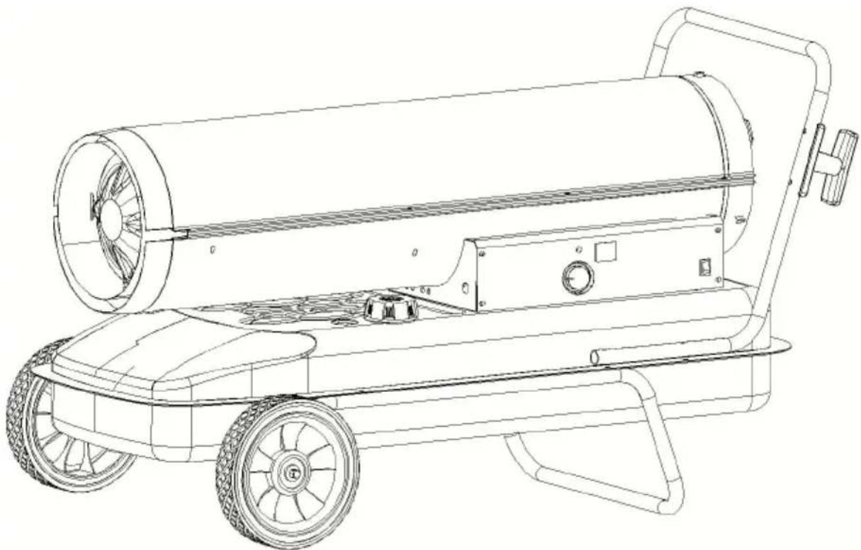
Fig. 1
Features
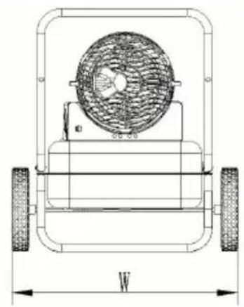
Figure 2
| Modèle | DG - K 70 | DG -K1 00 |
| L (mm) | 8 7 0 | 9 15 |
| L (mm) | 385 | 475 |
| Hmm) | 550 | 4 90 |
Unpacking
Fig. 3
Operation
Fig. 10 Nozzle Replacement
PETROLEUM HEATER
MODEL: DG-K70/DG-K100
VEVOR
Affordable. Reliable. Home Improvement.
KEROSENE HEATER
MODEL: DG-K70/DG-K100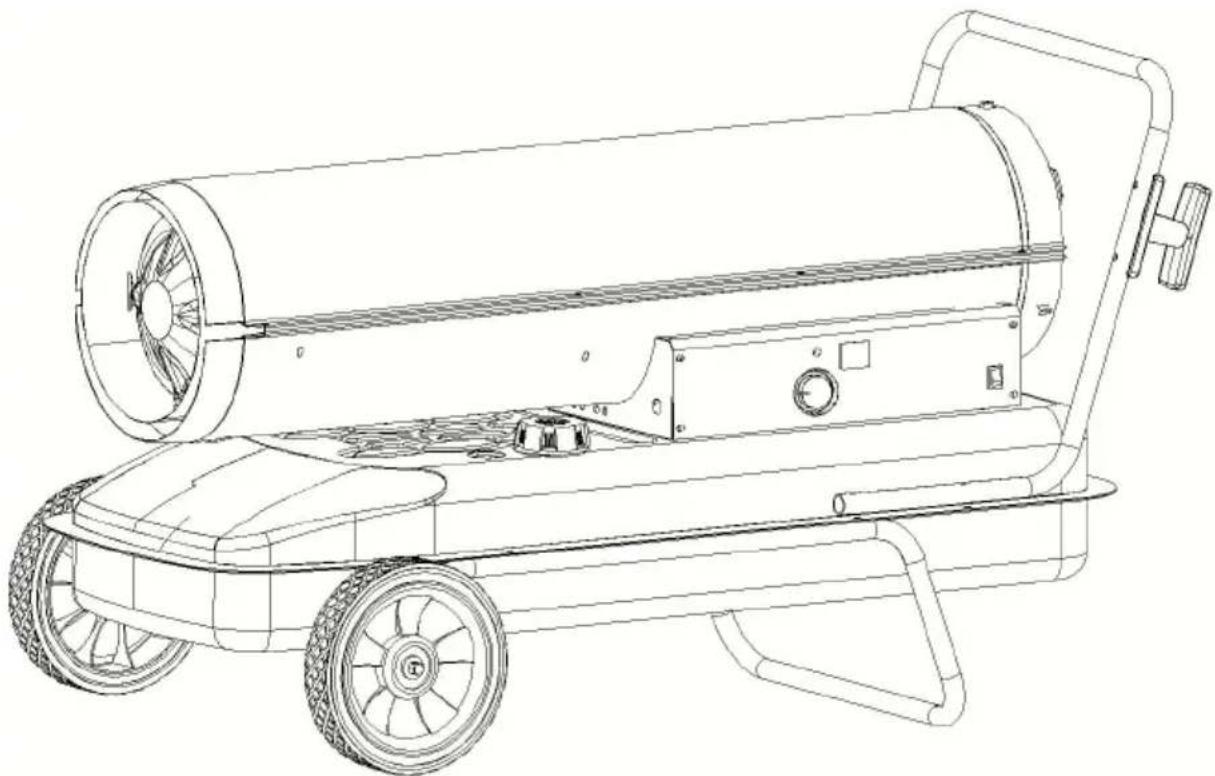
▲DANGER GENERAL HAZARD WARNING:
Fig.
1
Technical Data
Fig. 3
Operation

| NEIN # | Teilename | (TEILECODE FÜR MODELL) | Menge | |
| DG-K70 | DG-K100 | |||
| 1 | Shell | DG20-010000 | DG30-010000 | 1 |
| 2 | Untere Schale | DG20-020000 | DG30-020000 | 1 |
| 3 | Brennkammermontage | K70-030000 | K125-030000 | 1 |
| 4 | Kraftstofftankbaugruppe | K45-040000 | K125-040000 | 1 |
| 5 | Linke Seitenabdeckung | K70-050000 | K125-050000 | 1 |
| 6 | Rechte Seitenabdeckung | K45-060000 | K125-060000 | 1 |
| 7 | Motorhalterung | K45-100000 | K125-100000 | 1 |
| 8 | Lüfterbaugruppe | K45-110000 | K125-110000 | 1 |
| 9 | Handhaben | G10-010000 | 1 | |
| 10 | Ball | K215-121200 | K215-121200 | 1 |
| 11 | Frühling | K45-121300 | K45-121300 | 1 |
| 12 | Tankdeckel | K45-140000 | K45-140000 | 1 |
| 13 | Lüfterflügel Aluminiumbasis | K45-110101 | K45-110101 | 1 |
| 14 | Fotozellenhalterung | K45-230000 | K45-230000 | 1 |
| 15 | Thermostathalterung | K45-250100 | K45-250100 | 1 |
| 16 | Hinterer Griff | K125-300000 | 1 | |
| 17 | Radträgerrahmen | K125-310000 | 1 | |
| 18 | Radachse | K45-320001 | K125-320001 | 1 |
| 19 | Düsensitz | K45-070101 | K45-070101 | 1 |
| 20 | Brennerkopf | K45-070200 | K125-070200 | 1 |
| 21 | Nippel | K45-070400 | K45-070400 | 2 |
| 22 | Pumpenkörper | K45-120200 | K100-120200 | 1 |
| 23 | Rotorsatz | K45-120400 | K100-120400 | 1 |
| 24 | Klinge | K45-120500 | K100-120500 | 4 |
| 25 | Pumpendeckel abschließen | K45-120600 | K45-120600 | 1 |
| 26 | Düse | K70-070100 | K100-070100 | 1 |
| 27 | Rotor-Kit-Einsatz | K45-120300 | K45-120300 | 1 |
| 28 | Kraftstoffleitung | K70-080000 | K100-080000 | 1 |
| 29 | Luftlinie | K70-090000 | K100-090000 | 1 |
| 30 | Ausgangsfilter | K45-120700 | K45-120700 | 1 |
| 31 | Dichtung Auslassfilter | K45-120800 | K45-120800 | 1 |
| 32 | Flusenfilter | K45-120900 | K45-120900 | 1 |
| 33 | Filtersatz | K45-121000 | K45-121000 | 1 |
| 34 | Endfilterabdeckung | K45-121100 | K45-121100 | 1 |
| 35 | Einstellschraube | K45-121400 | K45-121400 | 1 |
| 36 | Lüfterschutz | K45-130000 | K125-130000 | 1 |
| 37 | Kraftstofffilter Nr. 1 | K45-140100 | K45-140100 | 1 |
| 38 | Netzkabelclip | K45-160000 | K45-160000 | 1 |
| 39 | Linke Leiterplattenhalterung | K45-190100 | K45-190100 | 1 |
| 40 | Rechte Leiterplattenhalterung | K45-190200 | K45-190200 | 1 |
| 41 | Kraftstofffilter Nr. 2 | K45-220100 | K125-220100 | 1 |
| 42 | Dichtungshülse | K45-220200 | K45-220200 | 1 |
| 43 | Verbindungsrohr für Kraftstofffilter Nr. 2 | K45-220300 | K125-220300 | 1 |
| 44 | Windows-Anzeige | K125-280000 | 1 | |
| 45 | Rad | K125-330001 | 2 | |
| 46 | Ablassschraube | BG06002DBX | 1 | |
| 47 | Abflussabstandshalter | K125-410000 | 1 | |
| 48 | Griffstecker | K125-390000 | 2 | |
| 49 | Zündkerzensatz | K45-070300 | K45-070300 | 1 |
| 50 | Motor | DG20-120100 | DG30-120100 | 1 |
| 51 | Luftdruckmesser | K125-121500 | 1 | |
| 52 | Netzkabel | K45-150000 | K45-150000 | 1 |
| 53 | Netzschalter | K45-170000 | K45-170000 | 1 |
| 54 | Zündgerät | DG20-180000 | DG20-180000 | 1 |
| 55 | Leiterplatte | K70-200001 | K125-200100 | 1 |
| 56 | Temperatursensor | K45-200120 | K45-200120 | 1 |
| 57 | Tankanzeige | K45-210000 | K125-210000 | 1 |
| 58 | Fotozelle | K45-240000 | K45-240000 | 1 |
| 59 | Thermostat | K45-250200 | K45-250200 | 1 |
| 60 | Anschlussleitung für Thermostat | K45-250300 | K45-250300 | 1 |
| 61 | Anschlussleitung für Netzkabel | K45-290000 | K45-290000 | 1 |
| 62 | Abstandshalter | K125-350000 | 2 | |
| 63 | Splint | BG06001DBX | 2 | |
| 64 | Kabelaufwicklung | K125-370000 | 2 | |

VEVOR
Affordable. Reliable. Home Improvement.
KEROSENE HEATER
MODEL: DG-K70/DG-K100
MODEL: DG-K70/DG-K100
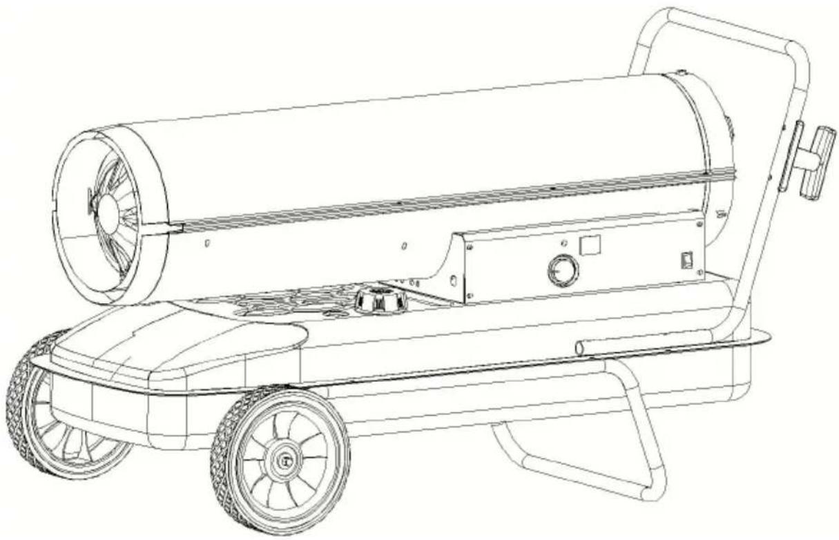
Figure 1
Specifications
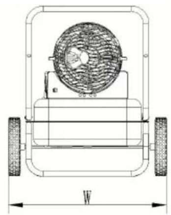
Figure 2
Figure 3
Operation

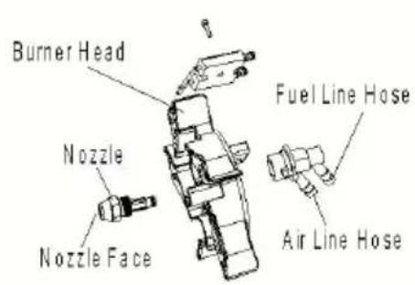
Figure 14 Fuel filter one
Affordable. Reliable. Home Improvement.
Figure 1
Budget
| Modelo | DG -K70 | DG -K 100 |
| Salida de calor ( kW | 20 | 30 |
| Consumo de combustible (L /h) | 1.9 | 2.9 |
| Tanque de combustible Capacidad ( L ) | 19 | 38 |
| Presión de la bomba ( / psi ) | 31/4.5 | 34.5/5 |
| Fuente de alimentación (V/Hz/A) | 220-240 / 5 0/ | 220-240 / 5 0 |
| Fase | soltero | soltero |
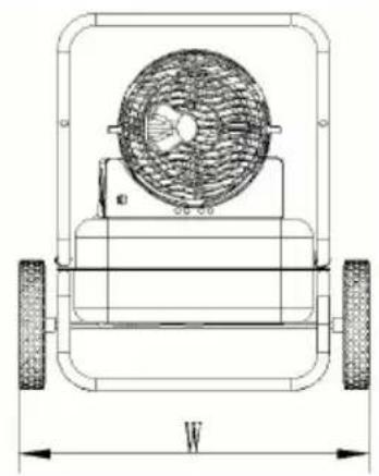
Figure 2
| Modelo | DG - K 70 | DG -K1 00 |
| Largo (mm ) | 8 7 0 | 9 15 |
| Ancho (mm) | 385 | 475 |
| Mmm) | 550 | 4 90 |
Unpacking
Figure 3
Operation
Diesel (or kerosene 1-K)
Figure 4 Temperature control switch
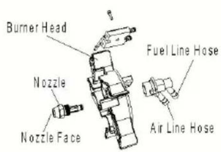
Figure 14 Fuel filter assembly
KEROSENE HEATER
MODELS: DG-K70/DG-K100
MODELS: DG-K70/DG-K100
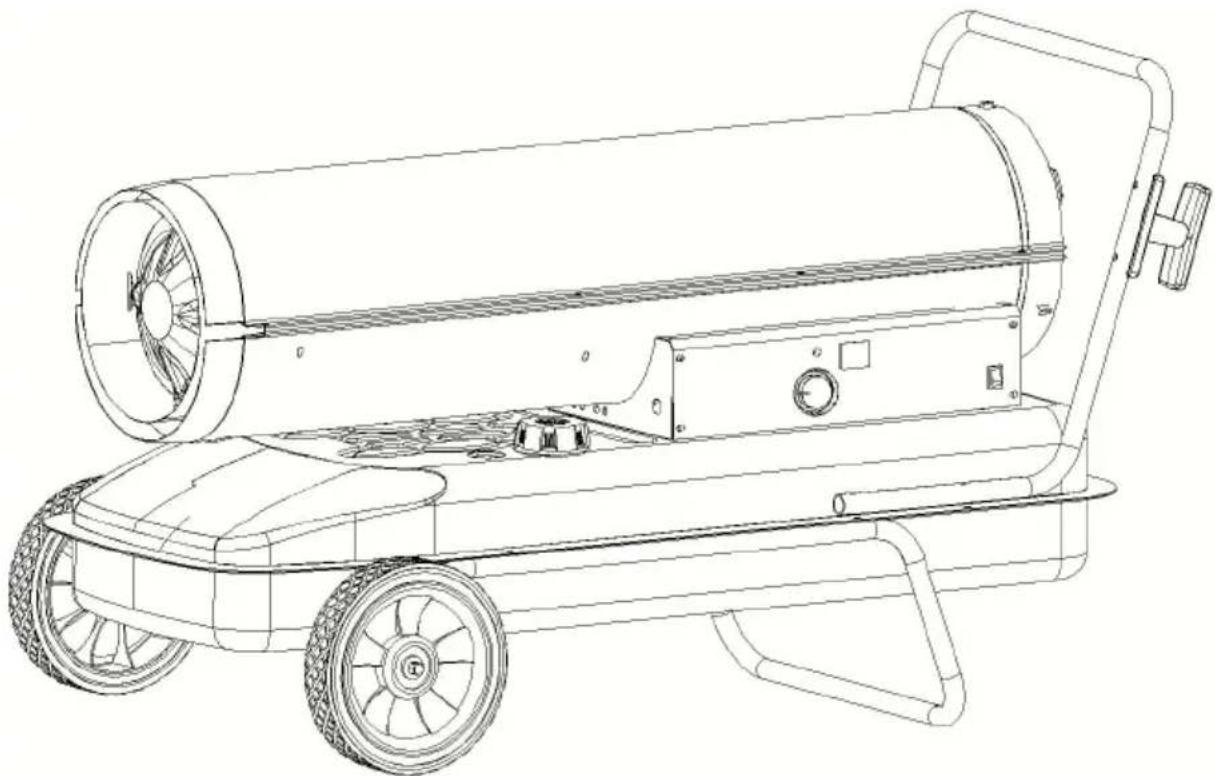
Fig.
1
Specifications
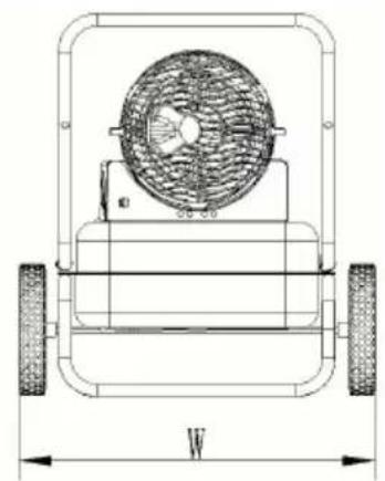
Fig. 2
Fig. 3
Operation
Diesel (or kerosene 1-K)
MODEL: DG-K70/DG-K100
MODEL: DG-K70/DG-K100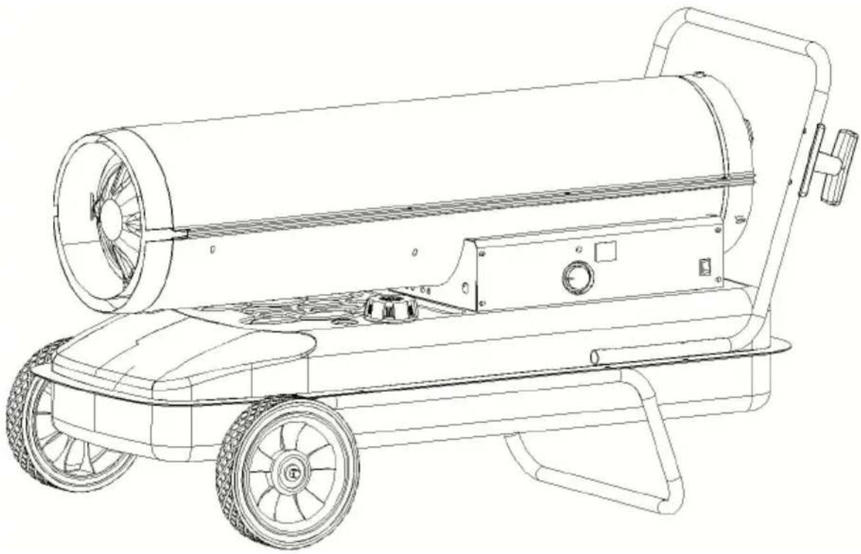
▲DANGER GENERAL HAZARD WARNING:
Figure 1
Figure 1 Specifications
| Model | DG -K70 | DG -K 100 |
| Warmteafgifte ( kW ) | 20 | 30 |
| Brandstofverbruik (L /uur) | 1.9 | 2.9 |
| Brandstoftank Inhoud ( I ) | 19 | 38 |
| Pompdruk ( kpa / psi) | 31/4.5 | 34,5/5 |
| Voeding (V/Hz/A) | 220-240 / 5 0/ | 220-240 / 5 0/ |
| Fase | enkel | enkel |
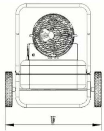
Figure 2
| Model | DG - K 70 | DG -K1 00 |
| Lengte (mm) | 8 7 0 | 9 15 |
| Breedte (mm) | 385 | 475 |
| Hoogte (mm) | 550 | 4 90 |
Unpacking
Figure 3
Operation
Diesel (or 1-K kerosene)

| NEE# | Onderdeelnaam | (ONDERDEELCODE VOOR MODEL) | Aantal | |
| DG-K70 | DG-K100 | |||
| 1 | Omhoog Shell | DG20-010000 | DG30-010000 | 1 |
| 2 | Onderste schelp | DG20-020000 | DG30-020000 | 1 |
| 3 | verbrandingskamer montage | K70-030000 | K125-030000 | 1 |
| 4 | Brandstoftankmontage | K45-040000 | K125-040000 | 1 |
| 5 | Linker zijdeksel | K70-050000 | K125-050000 | 1 |
| 6 | Rechter zijdeksel | K45-060000 | K125-060000 | 1 |
| 7 | Motormontagebeugel | K45-100000 | K125-100000 | 1 |
| 8 | Ventilatormontage | K45-110000 | K125-110000 | 1 |
| 9 | Hendel | G10-010000 | 1 | |
| 10 | Bal | K215-121200 | K215-121200 | 1 |
| 11 | lente | K45-121300 | K45-121300 | 1 |
| 12 | Tankdop | K45-140000 | K45-140000 | 1 |
| 13 | Ventilatorblad Aluminium basis | K45-110101 | K45-110101 | 1 |
| 14 | Fotocelbeugel | K45-230000 | K45-230000 | 1 |
| 15 | Thermostaatbeugel | K45-250100 | K45-250100 | 1 |
| 16 | Achterste handgreep | K125-300000 | 1 | |
| 17 | wielondersteuning Frame | K125-310000 | 1 | |
| 18 | wielas | K45-320001 | K125-320001 | 1 |
| 19 | Mondstukzitting | K45-070101 | K45-070101 | 1 |
| 20 | Branderkop | K45-070200 | K125-070200 | 1 |
| 21 | Nippel | K45-070400 | K45-070400 | 2 |
| 22 | Pomplichaam | K45-120200 | K100-120200 | 1 |
| 23 | Rotorkit | K45-120400 | K100-120400 | 1 |
| 24 | Blad | K45-120500 | K100-120500 | 4 |
| 25 | Eindpompdeksel | K45-120600 | K45-120600 | 1 |
| 26 | Mondstuk | K70-070100 | K100-070100 | 1 |
| 27 | rotor kit insert | K45-120300 | K45-120300 | 1 |
| 28 | Brandstofleiding | K70-080000 | K100-080000 | 1 |
| 29 | Luchtvaartmaatschappij | K70-090000 | K100-090000 | 1 |
| 30 | uitgangsfilter | K45-120700 | K45-120700 | 1 |
| 31 | Pakking uitlaatfilter | K45-120800 | K45-120800 | 1 |
| 32 | pluizenfilter | K45-120900 | K45-120900 | 1 |
| 33 | filterkit | K45-121000 | K45-121000 | 1 |
| 34 | Eindfilterdeksel | K45-121100 | K45-121100 | 1 |
| 35 | Afstelschroef | K45-121400 | K45-121400 | 1 |
| 36 | Ventilatorbescherming | K45-130000 | K125-130000 | 1 |
| 37 | Brandstofffilter #1 | K45-140100 | K45-140100 | 1 |
| 38 | Stroomkabelclip | K45-160000 | K45-160000 | 1 |
| 39 | Linker PCB-beugel | K45-190100 | K45-190100 | 1 |
| 40 | Rechter PCB-beugel | K45-190200 | K45-190200 | 1 |
| 41 | Brandstofffilter #2 | K45-220100 | K125-220100 | 1 |
| 42 | Afdichtingshuls | K45-220200 | K45-220200 | 1 |
| 43 | Brandstofffilter #2 verbindingsbuis | K45-220300 | K125-220300 | 1 |
| 44 | vensters weergeven | K125-280000 | 1 | |
| 45 | wiel | K125-330001 | 2 | |
| 46 | Afvoerschroef | BG06002DBX | 1 | |
| 47 | Afvoerafstandhouder | K125-410000 | 1 | |
| 48 | handgreep plug | K125-390000 | 2 | |
| 49 | Bougieset | K45-070300 | K45-070300 | 1 |
| 50 | Motor | DG20-120100 | DG30-120100 | 1 |
| 51 | Luchtdrukmeter | K125-121500 | 1 | |
| 52 | Stroomkabel | K45-150000 | K45-150000 | 1 |
| 53 | Aan/uit-schakelaar | K45-170000 | K45-170000 | 1 |
| 54 | Ontsteker | DG20-180000 | DG20-180000 | 1 |
| 55 | printplaat | K70-200001 | K125-200100 | 1 |
| 56 | Temperatuursensor | K45-200120 | K45-200120 | 1 |
| 57 | Brandstofmeter | K45-210000 | K125-210000 | 1 |
| 58 | Fotocel | K45-240000 | K45-240000 | 1 |
| 59 | Thermostaat | K45-250200 | K45-250200 | 1 |
| 60 | verbindingsleiding voor thermostaat | K45-250300 | K45-250300 | 1 |
| 61 | aansluitkabel voor netsnoer | K45-290000 | K45-290000 | 1 |
| 62 | afstandhouder | K125-350000 | 2 | |
| 63 | Splitpen | BG06001DBX | 2 | |
| 64 | Snoerwikkeling | K125-370000 | 2 | |

VEVOR
Affordable. Reliable. Home Improvement.
PHOTO HEATER
MODEL: DG-K70/DG-K100
VEVOR
Affordable. Reliable. Home Improvement.
KEROSENE HEATER
MODEL: DG-K70/DG-K100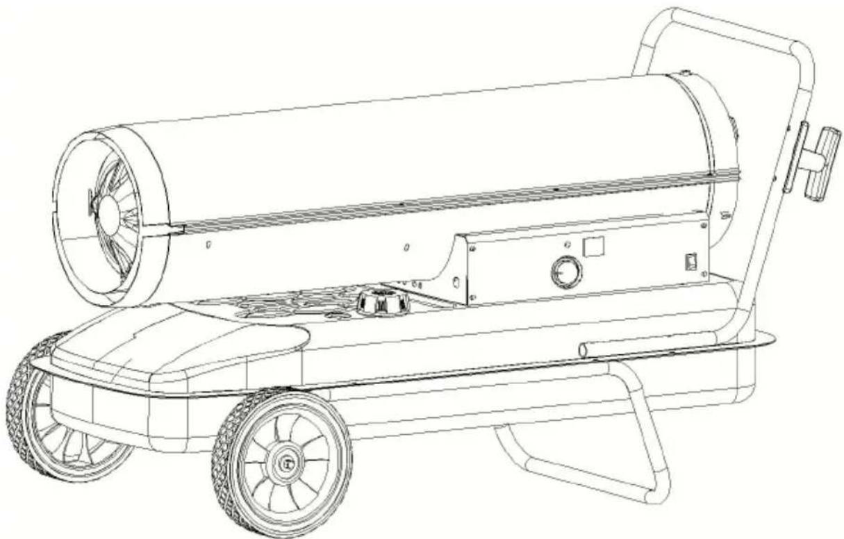
Figure 1
Specifications
Figure 2
| Modell | DG - K 70 | DG -K1 00 |
| Längd (mm) | 8 7 0 | 9 15 |
| B (mm) | 385 | 475 |
| H(mm) | 550 | 4 90 |
Unpacking
Figure 3
Operation
Diesel (or 1K kerosene)
TO START THE HEATER
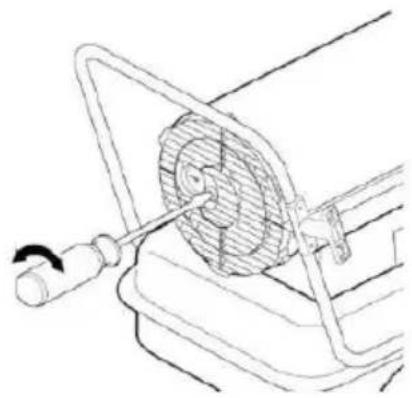
Figure 15. Adjusting the pump pressure
Wiring Diagram
| INGA # | Delnamn | (DELKOD FÖR MODELL) | Anta I | |
| DG-K70 | DG-K100 | |||
| 1 | Upp Shell | DG20-010000 | DG30-010000 | 1 |
| 2 | Nedre skal | DG20-020000 | DG30-020000 | 1 |
| 3 | förbränningskammaraggregat | K70-030000 | K125-030000 | 1 |
| 4 | Bränsletankmontering | K45-040000 | K125-040000 | 1 |
| 5 | Vänster sidokåpa | K70-050000 | K125-050000 | 1 |
| 6 | Höger sidokåpa | K45-060000 | K125-060000 | 1 |
| 7 | Motorfäste | K45-100000 | K125-100000 | 1 |
| 8 | Fläktaggregat | K45-110000 | K125-110000 | 1 |
| 9 | Hantera | G10-010000 | 1 | |
| 10 | Boll | K215-121200 | K215-121200 | 1 |
| 11 | fjädra | K45-121300 | K45-121300 | 1 |
| 12 | Tanklock | K45-140000 | K45-140000 | 1 |
| 13 | Fläktblad Aluminiumbas | K45-110101 | K45-110101 | 1 |
| 14 | Fotocellfäste | K45-230000 | K45-230000 | 1 |
| 15 | Termostatfäste | K45-250100 | K45-250100 | 1 |
| 16 | Bakre handtag | K125-300000 | 1 | |
| 17 | hjulstödram | K125-310000 | 1 | |
| 18 | hjulaxel | K45-320001 | K125-320001 | 1 |
| 19 | Munstyckssäte | K45-070101 | K45-070101 | 1 |
| 20 | Brännarhuvud | K45-070200 | K125-070200 | 1 |
| 21 | Nippel | K45-070400 | K45-070400 | 2 |
| 22 | Pumphus | K45-120200 | K100-120200 | 1 |
| 23 | Rotorsats | K45-120400 | K100-120400 | 1 |
| 24 | Blad | K45-120500 | K100-120500 | 4 |
| 25 | Ändpumpkåpa | K45-120600 | K45-120600 | 1 |
| 26 | Munstycke | K70-070100 | K100-070100 | 1 |
| 27 | rotorsatsinsats | K45-120300 | K45-120300 | 1 |
| 28 | Bränsleledning | K70-080000 | K100-080000 | 1 |
| 29 | Flygledning | K70-090000 | K100-090000 | 1 |
| 30 | utgångsfilter | K45-120700 | K45-120700 | 1 |
| 31 | Packning utloppsfilter | K45-120800 | K45-120800 | 1 |
| 32 | luddfilter | K45-120900 | K45-120900 | 1 |
| 33 | filterkit | K45-121000 | K45-121000 | 1 |
| 34 | Ändfilterlock | K45-121100 | K45-121100 | 1 |
| 35 | Justeringsskruv | K45-121400 | K45-121400 | 1 |
| 36 | Fläktskydd | K45-130000 | K125-130000 | 1 |
| 37 | Bränslefilter #1 | K45-140100 | K45-140100 | 1 |
| 38 | Nätsladdklämma | K45-160000 | K45-160000 | 1 |
| 39 | Vänster kretskortsfäste | K45-190100 | K45-190100 | 1 |
| 40 | Höger kretskortsfäste | K45-190200 | K45-190200 | 1 |
| 41 | Bränslefilter #2 | K45-220100 | K125-220100 | 1 |
| 42 | Tätningshylsa | K45-220200 | K45-220200 | 1 |
| 43 | Bränslefilter #2 anslutningsrör | K45-220300 | K125-220300 | 1 |
| 44 | Windows-skärm | K125-280000 | 1 | |
| 45 | hjul | K125-330001 | 2 | |
| 46 | Avtappningsskruv | BG06002DBX | 1 | |
| 47 | Avloppsdistans | K125-410000 | 1 | |
| 48 | handtagsplugg | K125-390000 | 2 | |
| 49 | Tändstiftssats | K45-070300 | K45-070300 | 1 |
| 50 | Motor | DG20-120100 | DG30-120100 | 1 |
| 51 | Lufttrycksmätare | K125-121500 | 1 | |
| 52 | Nätsladd | K45-150000 | K45-150000 | 1 |
| 53 | Strömbrytare | K45-170000 | K45-170000 | 1 |
| 54 | Tändare | DG20-180000 | DG20-180000 | 1 |
| 55 | PCB | K70-200001 | K125-200100 | 1 |
| 56 | Temperatursensor | K45-200120 | K45-200120 | 1 |
| 57 | Bränslemätare | K45-210000 | K125-210000 | 1 |
| 58 | Fotocell | K45-240000 | K45-240000 | 1 |
| 59 | Termostat | K45-250200 | K45-250200 | 1 |
| 60 | anslutningsledning för termostat | K45-250300 | K45-250300 | 1 |
| 61 | anslutningsledning för strömsladd | K45-290000 | K45-290000 | 1 |
| 62 | distans | K125-350000 | 2 | |
| 63 | Delad stift | BG06001DBX | 2 | |
| 64 | Sladdlindning | K125-370000 | 2 | |


- VEVOR
- KEROSENE HEATER
- CONSUMER: RETAIN THIS MANUAL FOR FUTURE REFERENCE
- ▲ DANGER GENERAL HAZARD WARNING
- ⚠ WARNING: NEVER LEAVE THE HEATER UNATTENDED WHILE BURNING OR WHILE CONNECTED TO A POWER SOURCE
- WARNING
- SAFETY INFORMATION
- ▲ DANGER: CARBON MONOXIDE POISONING MAY LEAD TO DEATH
- ⚠ WARNING: RISK OF INDOOR AIR POLLUTION
- ⚠ WARNING: RISK OF BURNS / FIRE / EXPLOSION
- ⚠ WARNING RISK OF ELECTRIC SHOCK
- FEATURES
- UNPACKING
- TOOL PREPARATION
- ASSEMBLING FRAME AND WHEELS
- CAUTION
- OPERATION
- THEORY OF OPERATION
- FUELING THE HEATER
- VENTILATION
- TO START THE HEATER
- EXTENSION CORD WIRE SIZE REQUIREMENTS ARE AS FOLLOWS
- TO STOP THE HEATER
- TO RESTART THE HEATER
- ELECTRICAL OUTLET
- ▲WARNING SHOCK HAZARD
- LONG TERM STORAGE
- MAINTENANCE
- ⚠ WARNING NEVER SERVICE HEATER WHILE IT IS PLUGGED IN OR WHILE
- FUEL/FUEL TANK
- AIR FILTERS
- FAN BLADES
- NOZZLES
- BE SURE FUEL USED IS APPROVED
- PHOTOCELL
- FUEL FILTER
- PUMP PRESSURE ADJUSTMENT
- TOLERANCE ±
- WIRING DIAGRAMS
- EXPLODED VIEW
- MODEL: DG-K70/DG-K
- ▲DANGER GENERAL HAZARD WARNING
- MODELS: DG-K70/DG-K
- FIGURE
- WIRING DIAGRAM
Brand : Vevor
Model : DG-K70
Category : Heating