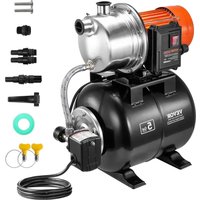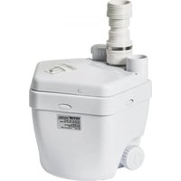
FLO500-RD - Water pump Vevor - Free user manual and instructions
Find the device manual for free FLO500-RD Vevor in PDF.


User questions about FLO500-RD Vevor
0 question about this device. Answer the ones you know or ask your own.
Ask a new question about this device
Download the instructions for your Water pump in PDF format for free! Find your manual FLO500-RD - Vevor and take your electronic device back in hand. On this page are published all the documents necessary for the use of your device. FLO500-RD by Vevor.
USER MANUAL FLO500-RD Vevor
Technical Support and E-Warranty Certificate
www.vevor.com/support
UTILITY SINK PUMP INSTRUCTIONS
MODEL: FLO500-RD
We continue to be committed to provide you tools with competitive price. "Save Half", "Half Price" or any other similar expressions used by us only represent estimate of savings you might benefit from buying certain tools with us compared top brands and does not necessarily mean to cover all categories of tools offered are kindly reminded to verify carefully when you are placing an order with us actually saving half in comparison with the top major brands.
VEVOR®
TOUGH TOOLS, HALF PRICE
UTILITY SINK PUMP
MODEL: FLO500-RD
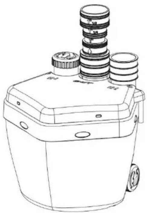
natural_image
Line drawing of a mechanical device with three cylindrical components and mounting holes (no text or symbols)Product drawing
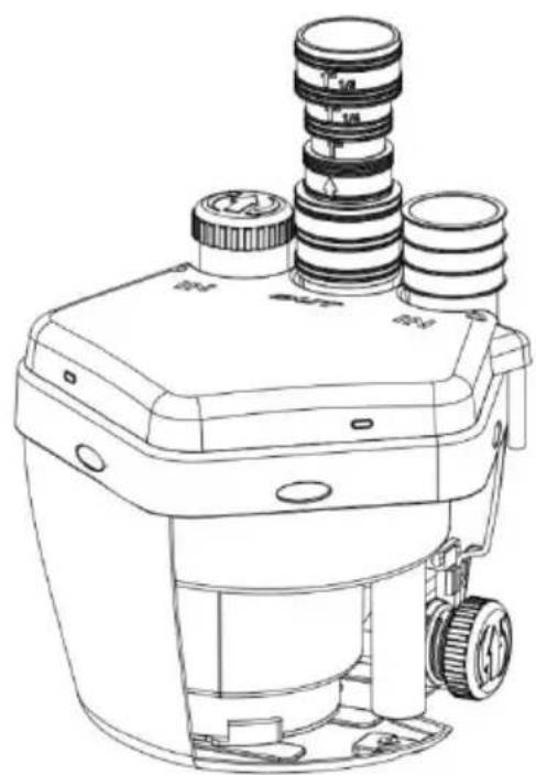
natural_image
Technical line drawing of a mechanical device with multiple cylindrical components and mounting base (no text or symbols)Interior view
NEED HELP? CONTACT US!
Have product questions? Need technical support? Please feel fr contact us:
Technical Support and E-Warranty Certificate www.vevor.com/support
This is the original instruction, please read all manual instruction carefully before operating. VEVOR reserves a clear interpretation user manual. The appearance of the product shall be subject to product you received. Please forgive us that we won't inform you there are any technology or software updates on our product.

Warning-To reduce the risk of injury, user must read instru manual carefully.
ATTENTION
SAVE THIS MANUAL
DESCRIPTION
This is a drain pump. That is ideally suitable for use in any section of where additional fixtures are needed. It will pump the waste water away variety of sources such as : laundry sink, washing machine (indirect or dishwasher, bar sink, etc.
WARNING
Read this material before using this product. Failure to do so can result in serious injury.
Before start-up, note the following:
The pump must be connected to a GFCI protected plug which has been installed according to regulations.
The plug must have a supply voltage of AC220-240V 50Hz.
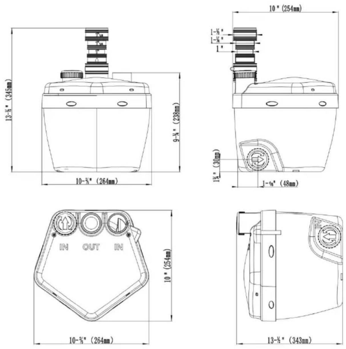
SPECIFICATION PARAMETERS
| Model | Input | Max Power | Max Flow | Max Lift | Outlet size |
| FLO500-RD | AC220-240V 50Hz | 400w | 6600 l/h | 5.5m | 1”、1-1/4” 1-1/2” |
CAUTION
This pump has been evaluated for use with water only.
IMPORTANT! For your own safety-before starting to run the pump, please have the following items checked by an expert:
following items checked by an expert:
-
Risk of electric shock-This pump is supplied with a grounding condu and grounding-type attachment plug. To reduce the risk of electric shock, be certain that it is connected only to a properly grounded, grounding-type receptacle.
-
Risk of electric shock - This pump has not been investigated for use
swimming pool areas.
- The electrical connections must be protected from moisture.
- If there is danger of flooding, the electrical connections must be taken higher ground.
- Circulation of caustic fluids, as well as the circulation of abrasive materials, must be avoided at all costs.
- The pump must be protected from frost.
- The pump must be protected from running dry.
- Access by children should also be prevented with appropriate measures
-
To prevent death from electric shock, pump must be connected only a GFCI protected outlet
-
Do not use an extension cord with this item.
11.WARNING:The cord of this product contains lead and/or di(2-ethylhephthalate (DEHP),chemicals known to the State of California to cause cancer, and birth defects or other reproductive harm.Wash hands after handling.
-
People with pacemakers should consult their physician(s) before use. Electromagnetic fields in close proximity to heart pacemaker could cause pacemaker interference or pacemaker failure.
-
The warnings, precautions, and instructions discussed in this instruction manual cannot cover all possible conditions and situations that may occur. It must be understood by the operator that common sense an caution are factors which cannot be built into this product, but must supplied by the operator.
Fluid Type
The Pump is designed for use with water with a maximum temperature 140^ F ( 60^ C). Do not use the pump for other fluids, especially not fuels, cleaning fluids, or other chemical products.
INSTALLATION
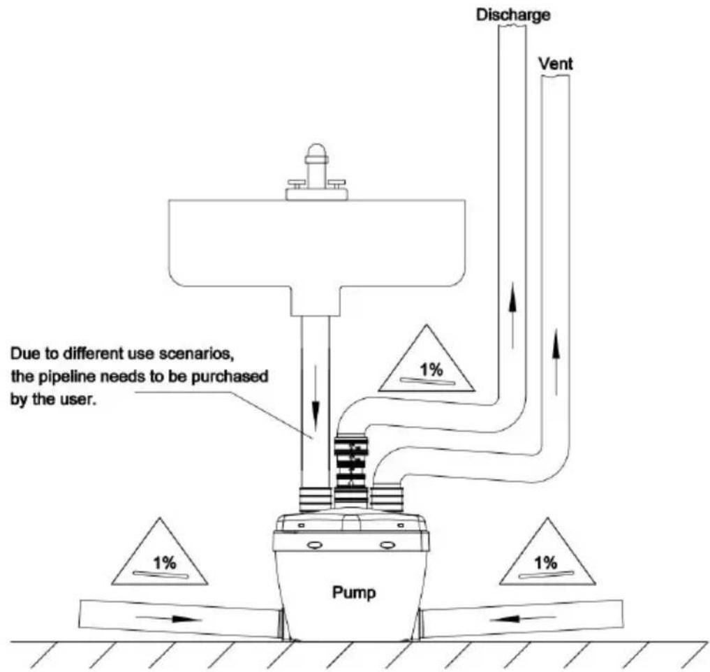
This appliance must be installed following our instruction manual and installation guidelines. It must also be installed in such a way as to
easy access for repair and maintenance and in accordance with local plumbing code.
flowchart
graph TD
    A["Discharge"] --> B["Pump"]
    C["Vent"] --> B
    B --> D["1%"]
    style A fill:#f9f,stroke:#333
    style C fill:#f9f,stroke:#333
    style D fill:#ccf,stroke:#333
    note1["Due to different use scenarios, the pipeline needs to be purchased by the user."] --> A
    note2["1%"] --> C
    note3["1%"] --> D
Connection to side inlets
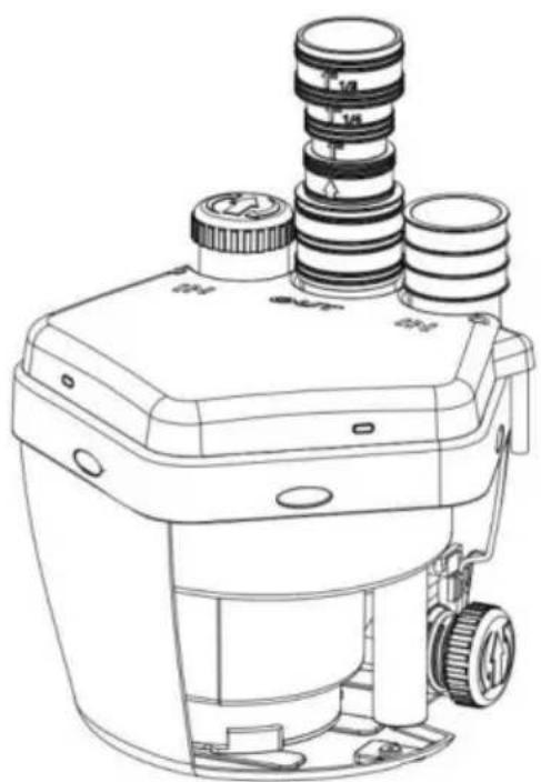
As shown in the picture above, the pump has two side inlets (one side) that are meant to connect additional fixtures. To connect to the inlets, one rubber coupling (1-1/2"x2") is provided along with the clamps. Use this rubber coupling to connect the side inlet to the PV coming from the fixture. An additional rubber coupling (with clamps) was needed if you want to use the other side inlet. If either side inlet is used, ensure that you cap off the inlet not being used by screwing cap into the case until it is completely sealed.
Connection to inlets (top)
To connect to the top inlets, one rubber (coupling) is provided along with the clamps. Use the rubber coupling to connect the top in the PVC pipe which should be from your vent connection. An addition
rubber coupling (with clamps) will be needed if you want to use the top inlet. If one of the top inlets is not being used, a cap is provic cover this inlet.
Connection to a bathtub / shower
When adding a bathtub / shower, a base will have to be constructed base should be made out of a 2"x 6"(minimum) or 2"x8" (recommend edge, to allow for the installation of a P-trap and the required 1/4" gravity flow towards the pump unit.
Discharge connection
The waste water being evacuated by this device must be discharged a 1, 1-1/4, 1-1/2 inch diameter copper or plastic (PVC, CPVC) pipe. pump is designed to handle 3/8" particles. The discharge pipe must I connected to a drain line or sewer line using an approved "Y" fitting designed for this purpose.
Make sure to only use 1", 1-1/4", 1-1/2" rigid pipe for the discharg as 45 degree elbows along installation .Do not use 90 degree elbows long sweeping elbows are not available, use two 45 degree elbows back-to-back to make a 90 degree tum.
Ensure that the angle of slope is 1/4" per foot for horizontal drain s leading up to the main drain stack to ensure drainage by gravity.
Install an optional full port ball valve at the bottom of the drain pipe allow shut off in case of repairs.
Vertical installation first
If vertical lift is required, this must precede the horizontal pipe run.
Connection to a ventilation system
The unit has been designed with a vent connection on the top of the All plumbing codes require a connection to a vent system. Connect y vent system using the provided 1-1/2"x 2" rubber coupling to connect you PVC pipe.
Please note that the vent system should be a two-way air vent. The mechanical vents, air admittance valves or similar devices are not permitted as these are considered one-way air vent systems.
Dismantling
(instructions intended for professionals only)
Disconnect the power supply before attempting any work on the device. This device does not require any specific maintenance. In case service required, any work on the device must be carried out by a technician
OPERATION
After reading these instructions, consider the following points before start the pump:
- Verify that the pump rests on the floor of the basin, if it is not sus by the handle.
- Verify that the discharge pipe is properly connected.
- Verify that the electrical connection is 22 0-24 0 VAC 50 Hz.
- Verify that the electrical socket is GFCI protected and in good condition. Test GFCI protected outlet before use.
- Verify that water and moisture cannot get near the power supply so
- Verify that the pump is installed so as to prevent running dry.
NOTE: The Pump will not start without 100m m of water.
NOTE: The Pump will remove water down to 20 mm. The Pump stop once 20 mm water level is reached.
NOTICE
Every time the pump is powered on, the motor will automatically start for 2 seconds as a self-test.
When the switch is turned off, the motor will be delayed for seconds to stop working.
WARNING
TO PREVENT SERIOUS INJURY FROM ACCIDENTAL OPERATION:
Unplug the Pump from its electrical outlet before performing any inspection, main-tenance, or cleaning procedures.
If the pump is moved during operation, flush it out with clean water a every use.
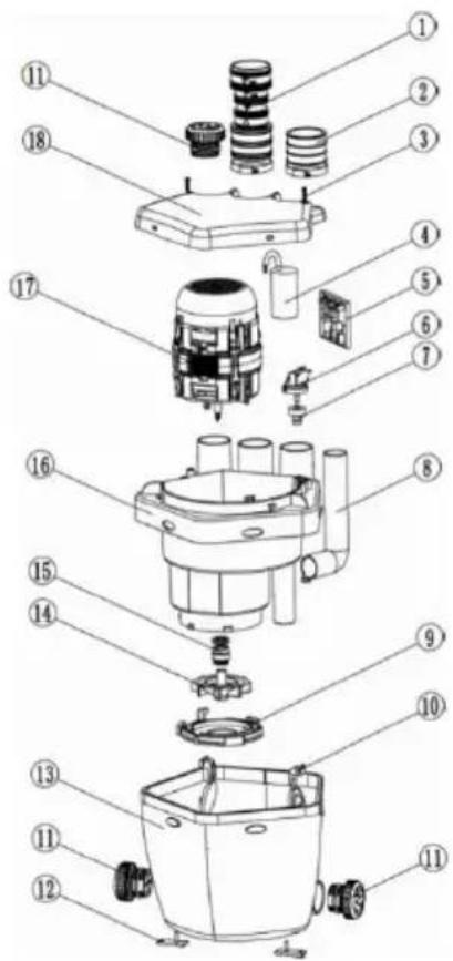
PART DRAWING
text_image
Exploded view diagram of a mechanical device with numbered parts for identificationDetail list of parts
| Item | Zero piece name | Quantity | Remark |
| 1 | Outlet pipe | 1 | |
| 2 | Inlet pipe | 1 | |
| 3 | Large pan head screws | 6 | |
| 4 | Electric capacity | 1 | |
| 5 | Electronic control board | 1 | |
| 6 | Micro-switch | 1 | |
| 7 | Switch seat | 1 | |
| 8 | Discharging tube | 1 | |
| 9 | Flow guide plate | 1 | |
| 10 | One-way valve | 2 | |
| 11 | Sultry cover | 3 | |
| 12 | Fixed plate | 2 | |
| 13 | Main body | 1 | |
| 14 | Impeller | 1 | |
| 15 | Mechanical seal | 1 | |
| 16 | Inner pump shell | 1 | |
| 17 | Motor parts | 1 | |
| 18 | Main cover | 1 |
REPAIR GUIDE
| Problem | Cause | Solution |
| The motor runs normally, but the water drains slowly. | The discharge pipe is blocked.Possible that the check valve is half closed. | Clean the discharge pipe .Inspect the check valve. |
| The water drain slowly and the motor works intermittently | Ventilation system blocked | Inspect the ventilation system. |
| The pump doesn’t start.The water doesn’t evacuate | There is no power going the pump. Thermal overload cut out. | Wait for the thermal overload to disengage (about 20-30 minutes) |
| The motor hum and it does not evacuate the water. | A foreign body is blocking impeller. Faulty capacitor. | Contact an authorized technician. |
| The water doesn't evacuate and the motor runs for a long time. | Evacuation pipe blocked. Partially blocked impeller | Contact an authorized technician. |
| After discharging the water,the motor restarts several times before stopping completely. | Water is flowing back into the pump. The check va doesn't close properly. | Drain clear water to free the che valve or remove the valve and o it. |
| The motor runs noisily, without either stopping pumping. | Siphoning or lack of counter pressure in the drainage pip creating an air pocket. Presence of a foreign body. | Modify the evacuation piping in suo way as to eliminate siphoning or increase the counter pressure (for example using smaller pipes, add a bend in the pipe). If the problem continues, contact an authorized technician. |
| The motor runs but makes a strange noise. | A foreign body has falle into the pump. | Contact an authorized technician. |
| The water back up into the shower tray or bathtub. | The outflow by gravity in pump is inadequate. Faulty inlet control flap or blocka in drain pipe. | Make sure that the gravity fall is least 1/4" per foot into the pump from the sanitary fixtures. |
VEVOR®
TOUGH TOOLS, HALF PRICE
Technical Support and E-Warranty Certificate
www.vevor.com/support
VEVOR®
TOUGH TOOLS, HALF PRICE
Assistance technique et certificat garantie
natural_image
Line drawing of a mechanical device with three cylindrical components and mounting holes (no text or symbols)Product drawing
natural_image
Line drawing of a mechanical device with multiple cylindrical components and mounting brackets (no text or symbols)Interior view
BESOIN D'AIDE? CONTACTEZ-NOUS!
flowchart
graph TD
    A["Pump"] --> B["Drain"]
    B --> C["Vent"]
    C --> D["Discharge"]
    D --> E["1%"]
    style A fill:#f9f,stroke:#333
    style B fill:#ccf,stroke:#333
    style C fill:#cfc,stroke:#333
    style D fill:#fcc,stroke:#333
    note right of A: 'Due to different use scenarios, the pipeline needs to be purchased by the user.'
    note right of B: '1%'
    note right of C: '1%'
text_image
Exploded view diagram of a mechanical assembly with numbered parts for identificationDetail list of parts
| Item | Zero piece name | Quantity | Remark |
| 1 | Outlet pipe | 1 | |
| 2 | Inlet pipe | 1 | |
| 3 | Large pan head screws | 6 | |
| 4 | Electric capacity | 1 | |
| 5 | Electronic control board | 1 | |
| 6 | Micro-switch | 1 | |
| 7 | Switch seat | 1 | |
| 8 | Discharging tube | 1 | |
| 9 | Flow guide plate | 1 | |
| 10 | One-way valve | 2 | |
| 11 | Sultry cover | 3 | |
| 12 | Fixed plate | 2 | |
| 13 | Main body | 1 | |
| 14 | Impeller | 1 | |
| 15 | Mechanical seal | 1 | |
| 16 | Inner pump shell | 1 | |
| 17 | Motor parts | 1 | |
| 18 | Main cover | 1 |
GUIDE DERÉPARATION
www.vevor.com/support
Spülbeckenpumpe
ANWEISUNGEN
MODELL: FLO500-RD
natural_image
Line drawing of a mechanical device with three cylindrical components and a base (no text or symbols)Product drawing
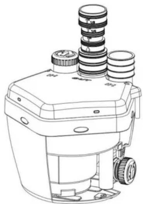
natural_image
Line drawing of a mechanical device with multiple cylindrical components and mounting base (no text or symbols)Interior view
flowchart
graph TD
    A["Pump"] --> B["Drain"]
    B --> C["Vent"]
    C --> D["Discharge"]
    D --> E["1%"]
    style A fill:#f9f,stroke:#333
    style B fill:#ccf,stroke:#333
    style C fill:#cfc,stroke:#333
    style D fill:#fcc,stroke:#333
    note right of A: 'Due to different use scenarios, the pipeline needs to be purchased by the user.'
    note right of B: '1%'
    note right of C: '1%'
text_image
Exploded view diagram of a mechanical assembly with numbered parts for identificationDetail list of parts
| Item | Zero piece name | Quantity | Remark |
| 1 | Outlet pipe | 1 | |
| 2 | Inlet pipe | 1 | |
| 3 | Large pan head screws | 6 | |
| 4 | Electric capacity | 1 | |
| 5 | Electronic control board | 1 | |
| 6 | Micro-switch | 1 | |
| 7 | Switch seat | 1 | |
| 8 | Discharging tube | 1 | |
| 9 | Flow guide plate | 1 | |
| 10 | One-way valve | 2 | |
| 11 | Sultry cover | 3 | |
| 12 | Fixed plate | 2 | |
| 13 | Main body | 1 | |
| 14 | Impeller | 1 | |
| 15 | Mechanical seal | 1 | |
| 16 | Inner pump shell | 1 | |
| 17 | Motor parts | 1 | |
| 18 | Main cover | 1 |
REPARATURANLEITUNG
www.vevor.com/support
VEVOR®
TOUGH TOOLS, HALF PRICE
www.vevor.com/support
POMPA LAVELLOUTILITÀ ISTRUZIONI
MODELLO: FLO500-RD
natural_image
Line drawing of a mechanical device with three cylindrical components and mounting holes (no text or symbols)Product drawing
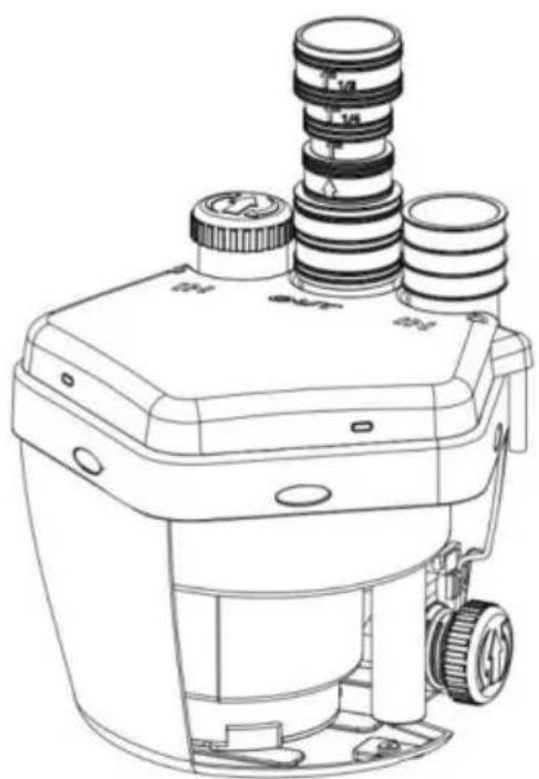
natural_image
Line drawing of a mechanical device with multiple cylindrical components and mounting brackets (no text or symbols)Interior view
HO BISOGNO DI AIUTOCONTATTACI!
text_image
13-½" (345mm) 9-¼" (238mm) 10-¾" (264mm)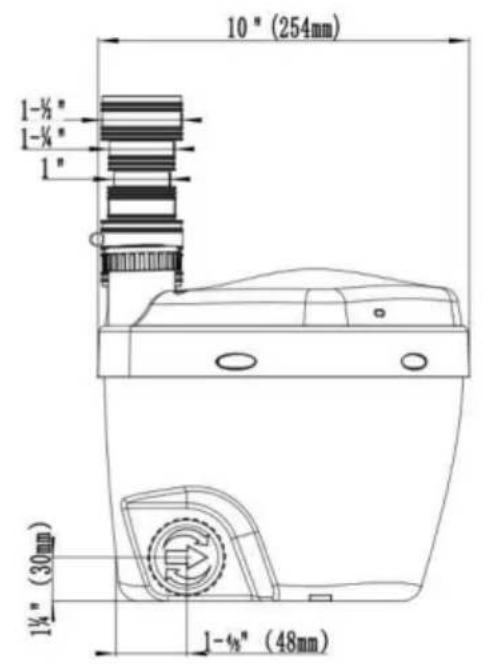
text_image
10" (254mm) 1-¼" 1-¼" 1" 1¼" (30mm) 1-¼" (48mm)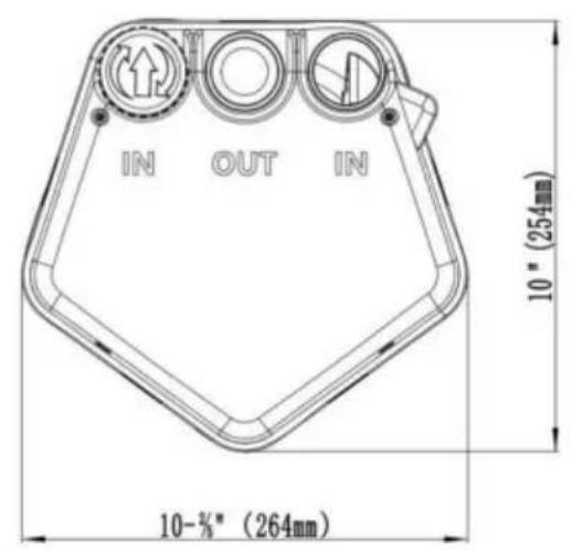
text_image
IN OUT IN 10" (254mm) 10-%* (264mm)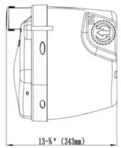
text_image
13-½" (343mm)ATTENZIONE
flowchart
graph TD
    A["Pump"] --> B["Drain"]
    B --> C["Vent"]
    C --> D["Discharge"]
    D --> E["1%"]
    style A fill:#f9f,stroke:#333
    style B fill:#ccf,stroke:#333
    style C fill:#cfc,stroke:#333
    style D fill:#fcc,stroke:#333
    note right of A: 'Due to different use scenarios, the pipeline needs to be purchased by the user.'
    note right of B: '1%'
    note right of C: '1%'
text_image
Exploded view diagram of a mechanical assembly with numbered parts for identificationDetail list of parts
| Item | Zero piece name | Quantity | Remark |
| 1 | Outlet pipe | 1 | |
| 2 | Inlet pipe | 1 | |
| 3 | Large pan head screws | 6 | |
| 4 | Electric capacity | 1 | |
| 5 | Electronic control board | 1 | |
| 6 | Micro-switch | 1 | |
| 7 | Switch seat | 1 | |
| 8 | Discharging tube | 1 | |
| 9 | Flow guide plate | 1 | |
| 10 | One-way valve | 2 | |
| 11 | Sultry cover | 3 | |
| 12 | Fixed plate | 2 | |
| 13 | Main body | 1 | |
| 14 | Impeller | 1 | |
| 15 | Mechanical seal | 1 | |
| 16 | Inner pump shell | 1 | |
| 17 | Motor parts | 1 | |
| 18 | Main cover | 1 |
elettronica www.vevor.com/support
VEVOR®
TOUGH TOOLS, HALF PRICE
natural_image
Line drawing of a mechanical device with three cylindrical components and mounting holes (no text or symbols)Product drawing
natural_image
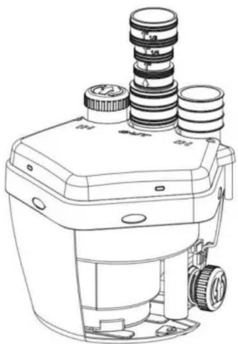
Line drawing of a mechanical device with multiple cylindrical components and mounting brackets (no text or symbols)Interior view
text_image
13-½" (345mm) 9-¼" (238mm) 10-¾" (264mm)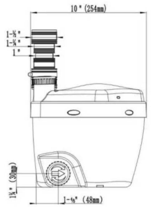
text_image
10" (254mm) 1-½" 1-¼" 1" 1½" (30mm) 1-¾" (48mm)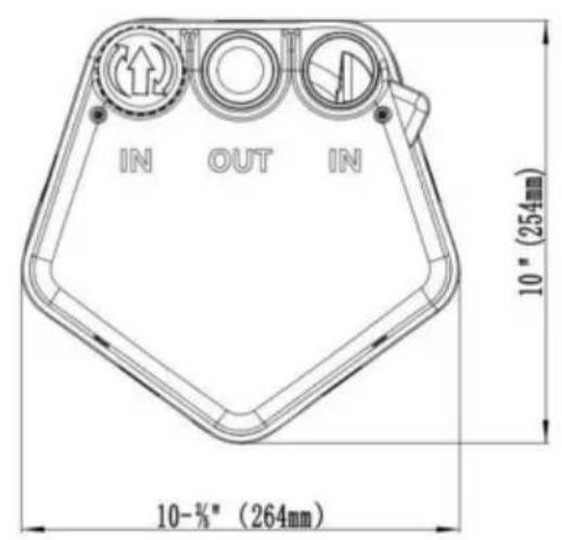
text_image
IN OUT IN 10" (254mm) 10-%* (264mm)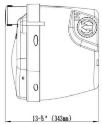
text_image
13-½" (343mm)PRECAUCIÓN
flowchart
graph TD
    A["Pump"] --> B["Drain"]
    B --> C["Vent"]
    C --> D["Discharge"]
    style A fill:#f9f,stroke:#333
    style B fill:#ccf,stroke:#333
    style C fill:#cfc,stroke:#333
    style D fill:#fcc,stroke:#333
    note1["Due to different use scenarios,<br>the pipeline needs to be purchased by the user."] --> B
    note2["1%"] --> B
    note3["1%"] --> B
text_image
Exploded view diagram of a mechanical assembly with numbered parts for identificationDetail list of parts
| Item | Zero piece name | Quantity | Remark |
| 1 | Outlet pipe | 1 | |
| 2 | Inlet pipe | 1 | |
| 3 | Large pan head screws | 6 | |
| 4 | Electric capacity | 1 | |
| 5 | Electronic control board | 1 | |
| 6 | Micro-switch | 1 | |
| 7 | Switch seat | 1 | |
| 8 | Discharging tube | 1 | |
| 9 | Flow guide plate | 1 | |
| 10 | One-way valve | 2 | |
| 11 | Sultry cover | 3 | |
| 12 | Fixed plate | 2 | |
| 13 | Main body | 1 | |
| 14 | Impeller | 1 | |
| 15 | Mechanical seal | 1 | |
| 16 | Inner pump shell | 1 | |
| 17 | Motor parts | 1 | |
| 18 | Main cover | 1 |
GUÍA DEREPARACIÓN
www.vevor.com/support
POMPA DO ZLEWU UŻYTKOWEGO
INSTRUKCJE
MODEL: FLO500-RD
natural_image
Line drawing of a mechanical device with three cylindrical components and mounting holes (no text or symbols)Product drawing
natural_image
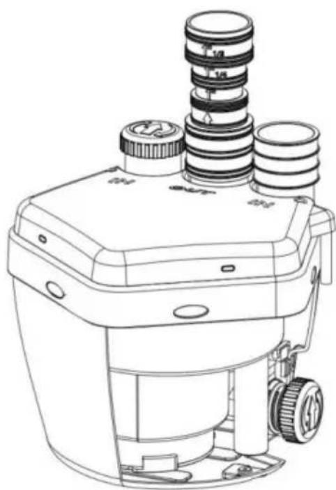
Technical line drawing of a mechanical device with multiple cylindrical components and mounting brackets (no text or symbols)Interior view
POTRZEBUJE POMOCY? SKONTAKTUJ SIĘ Z NAMI!
flowchart
graph TD
    A["Pump"] --> B["Drain"]
    B --> C["Vent"]
    C --> D["Discharge"]
    style A fill:#f9f,stroke:#333
    style B fill:#ccf,stroke:#333
    style C fill:#cfc,stroke:#333
    style D fill:#fcc,stroke:#333
    note1["Due to different use scenarios,<br>the pipeline needs to be purchased by the user."] --> B
    note2["1%"] --> B
    note3["1%"] --> B
text_image
Exploded view diagram of a mechanical assembly with numbered parts for identificationDetail list of parts
| Item | Zero piece name | Quantity | Remark |
| 1 | Outlet pipe | 1 | |
| 2 | Inlet pipe | 1 | |
| 3 | Large pan head screws | 6 | |
| 4 | Electric capacity | 1 | |
| 5 | Electronic control board | 1 | |
| 6 | Micro-switch | 1 | |
| 7 | Switch seat | 1 | |
| 8 | Discharging tube | 1 | |
| 9 | Flow guide plate | 1 | |
| 10 | One-way valve | 2 | |
| 11 | Sultry cover | 3 | |
| 12 | Fixed plate | 2 | |
| 13 | Main body | 1 | |
| 14 | Impeller | 1 | |
| 15 | Mechanical seal | 1 | |
| 16 | Inner pump shell | 1 | |
| 17 | Motor parts | 1 | |
| 18 | Main cover | 1 |
PRZEWODNIK NAPRAW
www.vevor.com/support
VEVOR®
TOUGH TOOLS, HALF PRICE
www.vevor.com/support
natural_image
Line drawing of a mechanical device with three cylindrical components and a base (no text or symbols)Product drawing
natural_image
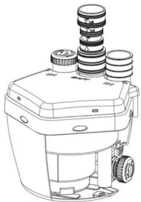
Line drawing of a mechanical device with multiple cylindrical components and mounting base (no text or symbols)Interior view
HULP NODIG? NEEM CONTACT MET ONS OP!
flowchart
graph TD
    A["Pump"] --> B["Drain"]
    B --> C["Vent"]
    C --> D["Discharge"]
    D --> E["1%"]
    style A fill:#f9f,stroke:#333
    style B fill:#ccf,stroke:#333
    style C fill:#cfc,stroke:#333
    style D fill:#fcc,stroke:#333
    note right of A: 'Due to different use scenarios, the pipeline needs to be purchased by the user.'
    note right of B: '1%'
    note right of C: '1%'
text_image
Exploded view diagram of a mechanical assembly with numbered parts for identificationDetail list of parts
| Item | Zero piece name | Quantity | Remark |
| 1 | Outlet pipe | 1 | |
| 2 | Inlet pipe | 1 | |
| 3 | Large pan head screws | 6 | |
| 4 | Electric capacity | 1 | |
| 5 | Electronic control board | 1 | |
| 6 | Micro-switch | 1 | |
| 7 | Switch seat | 1 | |
| 8 | Discharging tube | 1 | |
| 9 | Flow guide plate | 1 | |
| 10 | One-way valve | 2 | |
| 11 | Sultry cover | 3 | |
| 12 | Fixed plate | 2 | |
| 13 | Main body | 1 | |
| 14 | Impeller | 1 | |
| 15 | Mechanical seal | 1 | |
| 16 | Inner pump shell | 1 | |
| 17 | Motor parts | 1 | |
| 18 | Main cover | 1 |
REPARATIEGIDS
garantiecertificaat www.vevor.com/support
VEVOR®
TOUGH TOOLS, HALF PRICE
www.vevor.com/support
UTILITY SNK PUMP INSTRUKTIONER
MODELL: FLO500-RD
natural_image
Line drawing of a mechanical device with three cylindrical components and mounting holes (no text or symbols)Product drawing
natural_image
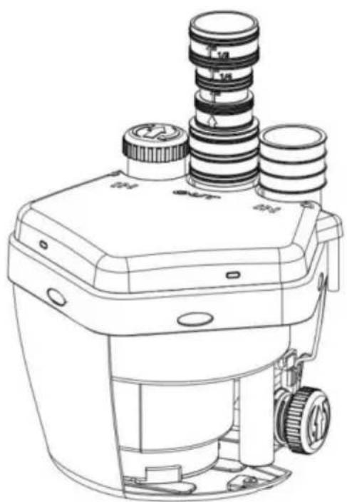
Line drawing of a mechanical device with multiple cylindrical components and mounting brackets (no text or symbols)Interior view
BEHÖVS HJÄLP? KONTAKTA OSS!
flowchart
graph TD
    A["Pump"] --> B["Drain"]
    B --> C["Vent"]
    C --> D["Discharge"]
    D --> E["1%"]
    style A fill:#f9f,stroke:#333
    style B fill:#ccf,stroke:#333
    style C fill:#cfc,stroke:#333
    style D fill:#fcc,stroke:#333
    note right of A: 'Due to different use scenarios, the pipeline needs to be purchased by the user.'
    note right of B: '1%'
    note right of C: '1%'
text_image
Exploded view diagram of a mechanical assembly with numbered parts for identificationDetail list of parts
| Item | Zero piece name | Quantity | Remark |
| 1 | Outlet pipe | 1 | |
| 2 | Inlet pipe | 1 | |
| 3 | Large pan head screws | 6 | |
| 4 | Electric capacity | 1 | |
| 5 | Electronic control board | 1 | |
| 6 | Micro-switch | 1 | |
| 7 | Switch seat | 1 | |
| 8 | Discharging tube | 1 | |
| 9 | Flow guide plate | 1 | |
| 10 | One-way valve | 2 | |
| 11 | Sultry cover | 3 | |
| 12 | Fixed plate | 2 | |
| 13 | Main body | 1 | |
| 14 | Impeller | 1 | |
| 15 | Mechanical seal | 1 | |
| 16 | Inner pump shell | 1 | |
| 17 | Motor parts | 1 | |
| 18 | Main cover | 1 |
REPARATIONSGUIDE
www.vevor.com/support