
HL750S - Log splitter SCHEPPACH - Free user manual and instructions
Find the device manual for free HL750S SCHEPPACH in PDF.

| Product type | Horizontal hydraulic log splitter |
| Brand | Scheppach |
| Model | HL750S |
| Dimensions (L x W x H) | 1100 x 380 x 640 mm |
| Weight | 55 kg |
| Power supply | 230 V~ / 50 Hz |
| Power consumption | 2300 W |
| Operating mode | S3 50% (intermittent periodic duty) |
| Max. splitting force | 7 tons |
| Piston stroke | 400 mm |
| Piston advance speed | 37 mm/s |
| Piston return speed | 70 mm/s |
| Hydraulic oil capacity | 4.2 liters (recommended HLP 32) |
| Working pressure | 240 bar |
| Permissible log diameter | 50 to 250 mm |
| Permissible log length | 150 to 520 mm |
| Sound pressure level (LpA) | 70.3 dB(A) (uncertainty 1.5 dB) |
| Sound power level (LWA) | 83.8 dB(A) |
| Safety devices | Two-hand control, protective covers, automatic shutdown |
| Regular maintenance | Cleaning after each use, lubrication of guide rails, checking oil level before each start-up |
| Oil change | Every 150 operating hours |
| Wear parts | Splitting wedge, hydraulic oil, log guides |
| Warranty | Statutory, visible defects must be reported within 8 days after receipt |
Frequently Asked Questions - HL750S SCHEPPACH
User questions about HL750S SCHEPPACH
0 question about this device. Answer the ones you know or ask your own.
Ask a new question about this device
Download the instructions for your Log splitter in PDF format for free! Find your manual HL750S - SCHEPPACH and take your electronic device back in hand. On this page are published all the documents necessary for the use of your device. HL750S by SCHEPPACH.
USER MANUAL HL750S SCHEPPACH
natural_image
Black industrial machine with visible internal components and 'Scheeppach' branding on the side (no other text or symbols)
HL750S
| DE | HolzspalterOriginalbedienungsanleitung | 07 |
| GB | Log splitterTranslation of original instruction manual | 18 |
| FR | Fendeuse de boisTraduction des instructions d'origine | 27 |
| IT | SpaccalegnaTraduzione dal libretto d'istruzione originale | 37 |
| CZ | Štípač dřevaPřeklad z originálního návodu | 47 |
| SK | Štiepačka drevaPreklad originálu - Úvod | 56 |
| EE | PuulôhkujaTõlge Originaalkasutusjuhendi | 65 |
| LT | Medienos skaldytuvas Vertimas originali naudojimo instrukcija | 74 |
| LV | Malkas skaldītājs Tulkošana no originala lietošanas instrukcija | 83 |
| HU | Fahasító Az eredeti használati útmutató fordítása | 92 |
| SI | Cepilnik drv Prevod originalnega navodila za uporabo | 101 |
| HR | Cjepač drva Prijevod originalnog priručnika za uporabu | 110 |
| PL | Łuparka klinowa do drewna Tłumaczenie oryginalnej instrukcji obsługi | 119 |
1
11
12
natural_image
Technical line drawing of a mechanical device with internal components and liquid pouring into a container (no text or symbols)Günzburger Straße 69
D-89335 Ichenhausen
Verehrter Kunde
Explanation of the symbols on the device
Symbols are used in this manual to draw your attention to potential hazards. The safety symbols and the accompanying explanations must be fully understood. The warnings themselves will not rectify a hazard and cannot replace proper accident prevention measures.
 | Read the manual before commissioning. |
 | Wear hearing protection. Excessive noise can result in a loss of hearing. |
 | Wear safety gloves. |
 | Wear safety goggles. |
 | Use work gloves. |
 | Removing or modifying protective or safety equipment is prohibited. |
 | Do not let hydraulic oil run onto the floor.Dispose of waste oil properly at the on-site waste oil collection point. Dumping used oil in the soil or mixing it with waste is prohibited. |
 | Do not use the device in wet conditions! Protect from moisture! |
 | Attention! Before starting repair, maintenance and cleaning work, switch off the engine and unplug the mains plug. |
 | High voltage, risk of death! |
 | Do not reach into the splitting area!Danger of injury! Danger of cutting and crushing! |
 | Do not reach into the machine unprotected! |
 | Attention! Moving parts! |
 | Only the operator may stand in the working area of the machine. Keep uninvolved persons as well as pets and livestock away from the danger zone (minimum distance 5 m). |
| △ Attention! | We have marked points in these operating instructions that impact your safety with this symbol |
Table of contents: Page:
- Introduction......20
- Device description....20
- Scope of delivery....20
- Proper use....20
- General safety instructions....21
- Additional safety instructions.... 21
- Technical data 22
- Unpacking 22
- Assembly / Before commissioning 22
- Commissioning....23
- Electrical connection 24
- Cleaning 24
- Transport 24
- Storage....24
- Maintenance....24
- Disposal and recycling 25
- Troubleshooting....26
1. Introduction
Manufacturer:
scheppach
Günzburger Straße 69
D-89335 Ichenhausen
Dear Customer
We hope your new tool brings you much enjoyment and success.
Note:
In accordance with the applicable product liability laws, the manufacturer of this device assumes no liability for damage to the device or caused by the device arising from:
- Improper handling
- Failure to comply with the operating instructions.
- Repairs carried out by third parties, unauthorised specialists
- Installing and replacing non-original spare parts,
- Improper use
- Failures of the electrical system in the event of the electrical regulations and VDE provisions 0100, DIN 57113 / VDE 0113 not being observed
Note:
Read the whole text of the operating manual before assembly and commissioning.
This operating manual should help you to familiarise yourself with your device and to use it for its intended purpose.
The operating manual includes important instructions for safe, proper and economic operation of the device, for avoiding danger, for minimising repair costs and downtimes, and for increasing the reliability and extending the service life of the device.
In addition to the safety instructions in this operating manual, you must also observe the regulations applicable to the operation of the device in your country.
Keep the operating manual at the device, in a plastic sleeve, protected from dirt and moisture. They must be read and carefully observed by all operating personnel before starting the work.
The device may only be used by personnel who have been trained to use it and who have been instructed with respect to the associated hazards. The required minimum age must be observed.
In addition to the safety instructions in this operating manual and the separate regulations of your country, the generally recognised technical rules relating to the operation of such machines must also be observed.
We accept no liability for accidents or damage that occur due to a failure to observe this manual and the safety instructions.
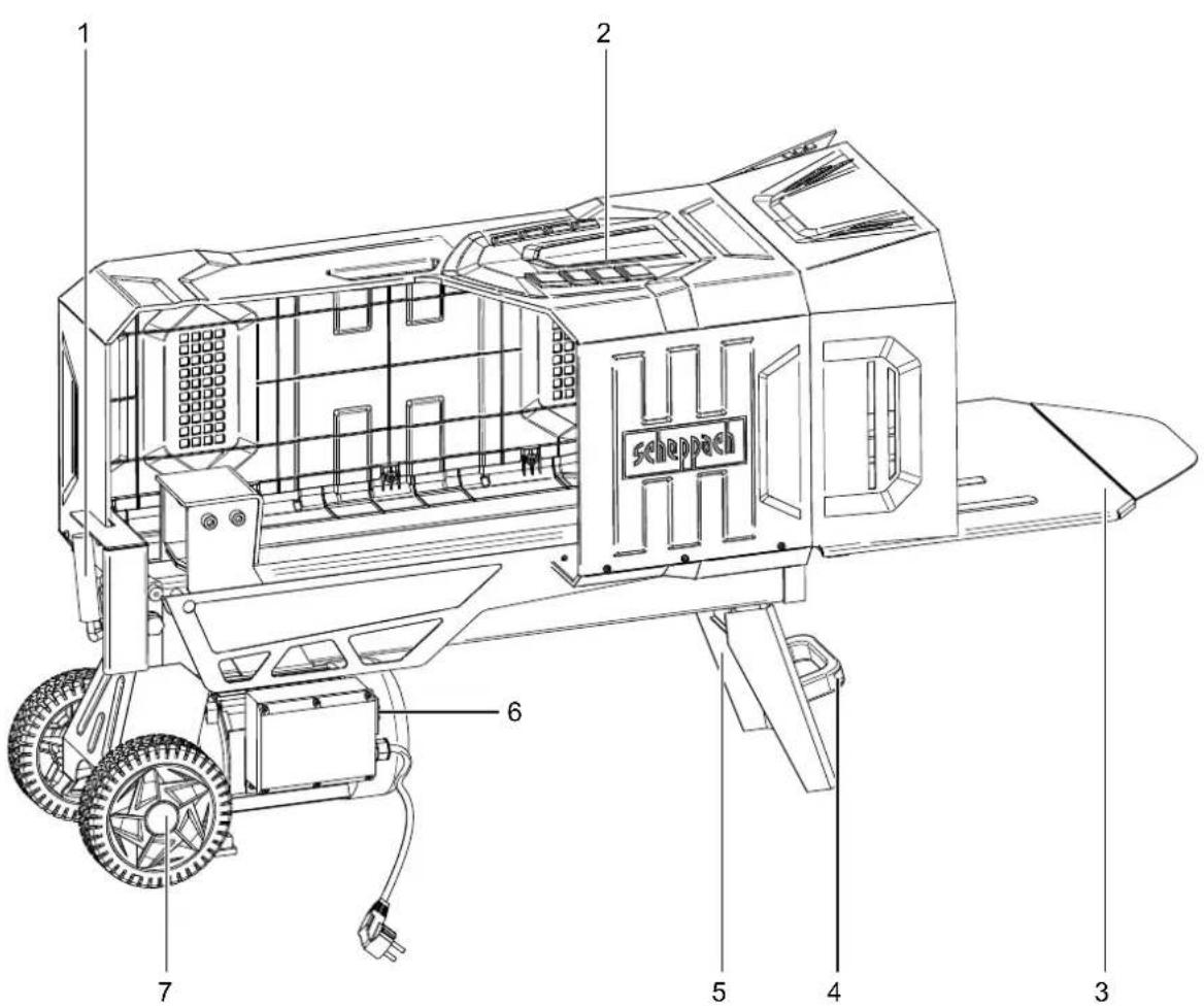
2. Device description
- Control handle (hydraulic)
- Guard
- Tray table
- Transport handle
- Foot
- Control button (electric motor)
- Transport wheels
- Pressure plate
- Ventilation screw
3. Scope of delivery
A. Log splitter
B. Lower cover (large)
C. Lower cover (small)
D. Side cover (large)
E. Side flap
F. Side cover (small)
G. Rear side cover
H. Upper flap
I. Upper cover
J. Corner connection
K. Oil drain screw with oil dipstick
L. Enclosed accessories bag
c. Safety ring (2x)
d. Wheel cap
e. Cylindrical screw M4 x 12 mm (17x)
f. Hexagon screw M8 x 20 mm (1x)
g. Hexagon nut (M4) (17x)
a. Hexagon screw M6 x 16 mm + washers (2x)
b. Cylindrical screw M6 x 20 mm + washers and hexagonal nuts (2x)
4. Proper use
The machine may only be used in the intended manner. Any use beyond this is improper. The user/operator, not the manufacturer, is responsible for damages or injuries of any type resulting from this.
An element of the intended use is also the observance of the safety instructions, as well as the assembly instructions and operating information in the operating manual.
Persons who operate and maintain the machine must be familiar with it and must be informed about potential dangers.
In addition, the applicable accident prevention regulations must be strictly observed.
Other general occupational health and safety-related rules and regulations must be observed.
The liability of the manufacturer and resulting damages are excluded in the event of modifications of the machine.
- The hydraulic log splitter is only suitable for horizontal operation. Timbers may only be split horizontally in the direction of the grain. The dimensions of the timbers to be split are a maximum of 52 cm.
- Never split wood vertically or against the grain!
- The safety, operating and maintenance specifications of the manufacturer, as well as the dimensions specified in the technical data, must be observed.
- The applicable accident prevention regulations and the other generally accepted safety rules must be observed.
- The machine may only be used, maintained or repaired by competent persons who are familiar with it and have been informed of the dangers. Any liability of the manufacturer for damages resulting from arbitrary changes to the machine is excluded.
- The machine may only be operated with original accessories and original tools from the manufacturer.
- Any use beyond this is improper use. The manufacturer is not responsible for the resultant damages, the user bears this risk alone.
- Keep the work area clean and free of obstructions.
- Only operate the device on a flat, firm surface.
- Before each commissioning, check that the splitter is functioning properly.
- Only operate the device in areas that are a maximum of 1000 m above sea level.
Please note that our equipment was not designed with the intention of use for commercial or industrial purposes. We assume no guarantee if the device is used in commercial or industrial applications, or for equivalent work.
5. General safety instructions
WARNING: When using power tools, the basic safety precautions below must be followed in order to reduce the risk of fire, electric shock, and personal injury. Please read all instructions before working with this tool.
- Observe all safety information and danger notices on the machine.
- Ensure that all of the safety information and danger notices on the machine are complete and in legible condition.
- The safety equipment on the machine must not be disassembled or made unusable.
- Check mains connection cables. Do not use faulty connection cables.
- Check for correct function of the two-hand control before commissioning.
-
The operating personnel must be at least 18 years of age. Trainees must be at least 16 years of age and may only work on the machine under supervision.
• Children may not work with this device -
Wear work and safety gloves, safety goggles, close-fitting work clothes, and hearing protection (PPE) while working.
- Caution when working: Danger of injury for fingers and hands due to the splitting tool.
- Modification, adjustment and cleaning work, as well as maintenance and rectification of faults may only be carried out when the engine is switched off. Pull out the mains plug!
• Installation, repairs and maintenance work on the electrical equipment may only be carried out by electricians. - All protective and safety equipment must be reassembled immediately after repair and maintenance work is completed.
- Switch off the engine when leaving the work station. Pull out the mains plug!
- Removing or working without guards is prohibited.
- When splitting, the properties of the wood (e.g. growths, trunk slices of irregular shape, etc.) can result in hazards such as ejecting parts, splitter blocking, and crushing.
6. Additional safety instructions
- The log splitter may only be operated by a single person.
- Never split trunks that contain nails, wire, or other objects.
- Wood that has already been split and wood chippings create a hazardous work area. There is a danger of tripping, slipping or falling. Always keep the work area orderly.
- Never place your hands on moving parts of the machine when it is switched on.
- Only split wood with a maximum length of 52 cm.
Warning! This power tool generates an electromagnetic field during operation. This field can impair active or passive medical implants under certain conditions. In order to prevent the risk of serious or deadly injuries, we recommend that persons with medical implants consult with their physician and the manufacturer of the medical implant prior to operating the power tool.
Residual risks
The machine has been built according to the state-of-the-art and the recognised technical safety requirements. However, individual residual risks can arise during operation.
- Danger of injury for fingers and hands from the splitting tool in the event of improper guiding or support of the wood.
-
Injuries due to the workpiece being ejected at high speed due to improper holding or guiding.
-
Health hazard due to electrical power, with the use of improper electrical connection cables.
- Before performing setting or maintenance work, release the start button and pull out the power plug.
• Furthermore, despite all precautions having been met, some non-obvious residual risks may still remain. - Residual risks can be minimised if the "Safety Instructions" and the "Intended Use" together with the operating manual as a whole are observed.
- Avoid accidental starting of the machine: the operating button may not be pressed when inserting the plug in an outlet. Use the tool that is recommended in this operating manual. This is how to ensure that your machine provides optimum performance.
- Keep your hands away from the working area when the machine is in operation.
7. Technical data
Dimensions L x W x H 1100 x 380 x 640 mm
| Wood ø min - max 50 - 250 mm | |
| Wood length min - max 150 - 520 mm | |
| Weight approx. | 55 kg |
| Engine | 230V~ / 50 Hz |
| Rated input | 2300 W |
| Operating mode | S3 50% |
| Splitting force | max. 7 t |
| Cylinder stroke | 400 mm |
| Cylinder forward stroke | 37 mm/sec |
| Cylinder reverse stroke | 70 mm/sec |
| Oil quantity | 4.2 l |
| Operating pressure | 240 bar |
| Speed | 2800 min ^-1 |
Technical changes reserved!
Noise and vibration
⚠ Warning: Noise can have serious effects on your health. If the machine noise exceeds 85 dB (A), please wear suitable hearing protection.
Noise data
| Sound power level L_WA | 83.8 dB (A) |
| Sound pressure level L_pA | 70.3 dB (A) |
| Uncertainty K_WA/pA | 1.5 dB (A) |
*Operating mode S3, periodic intermittent operation without start-up process influence on the engine warming up. The mode comprises of a start-up period, a time with constant load and an idle time. The operating time is 10 mins, the relative duty cycle is 50% of the operating time.
Pressure:
The performance level of the built-in hydraulic pump can reach a brief pressure level for a splitting force of up to 7 tons. In the basic setting, hydraulic splitters are set at the factory to an approx. 10% lower output level. For safety reasons, the basic settings must not be changed by the user. Please note that external circumstances such as operating and ambient temperature, air pressure and moisture affect the viscosity of the hydraulic oil. In addition, manufacturing tolerances and maintenance errors can affect the reachable pressure level.
8. Unpacking
- Open the packaging and carefully remove the device.
- Remove the packaging material, as well as the packaging and transport safety devices (if present).
- Check whether the scope of delivery is complete.
- Check the device and accessory parts for transport damage. In the event of complaints the carrier must be informed immediately. Later claims will not be recognised.
- If possible, keep the packaging until the expiry of the warranty period.
- Familiarise yourself with the product by means of the operating instructions before using for the first time.
- With accessories as well as wearing parts and replacement parts use only original parts. Replacement parts can be obtained from your dealer.
- When ordering please provide our article number as well as type and year of manufacture for your equipment.
⚠ Attention!
The device and the packaging material are not children's toys! Do not let children play with plastic bags, films or small parts! There is a danger of choking or suffocating!
9. Assembly / Before commissioning
At least two people are required to install the device.
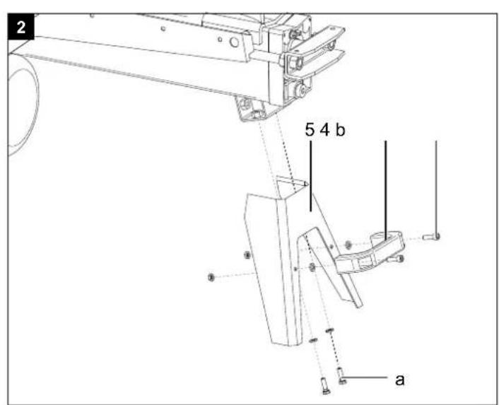
9.1 Fitting the machine foot (fig. 2)
- Mount the machine foot (5) using two hexagon screws (b) and washers on the holes provided.
9.2 Fitting the handle (fig. 2)
- Mount the handle (4) using two Allen screws (b), two washers and two thin nuts on the holes provided on the machine foot.
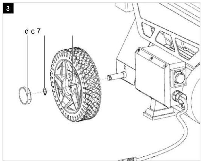
9.3 Fitting the wheels (fig. 3)
• Fit the wheels (7) on the axles.
- Secure the wheels (7) using the provided locking rings (c).
- Fit the wheel caps (d) on the wheels.
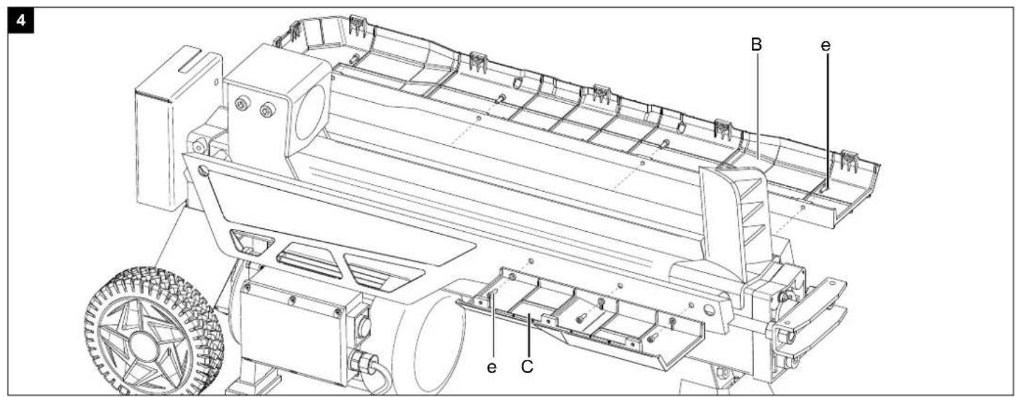
9.4 Installing the protective guard (Fig. 4 - 8)
- Mount the lower cover (B) to the right side of the machine using four Allen screws (e). (Fig. 4)
- Mount the lower cover (C) to the left side of the machine using three Allen screws (e) (fig. 4)
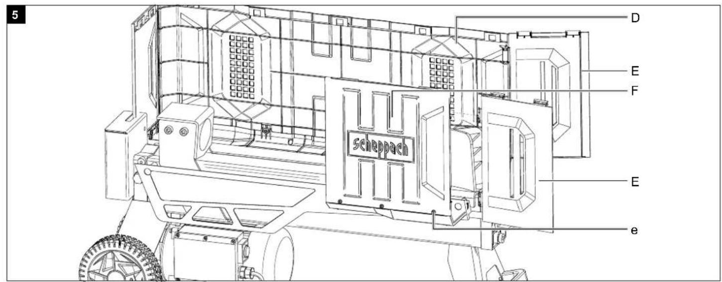
- Fit the side cover (D) into the lower cover (B) and secure it with five Allen screws (e) and five hexagon nuts (g). (fig. 5)
- Fit the side cover (F) into the lower cover (C) and secure it with three Allen screws (e) and three hexagon nuts (g). (fig. 5)
- Connect the holders of the side flaps (E) with the hinges of the side cover (D) and (F). (fig. 5)
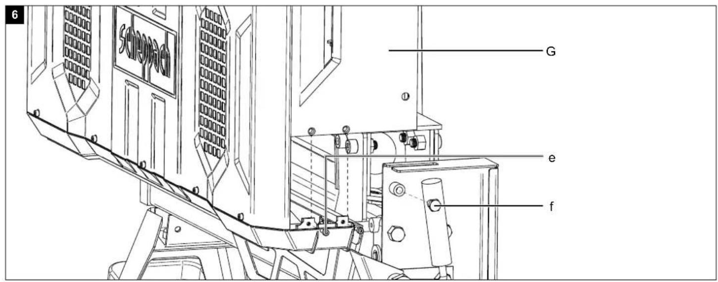
- Fit the rear side cover (D) into the lower cover (B) and into the side cover (D) and secure it with two Allen screws (e) and two hexagon nuts (g). (Fig. 6)
- Secure the rear side cover (G) with the hexagon screw (f). To do this, you have to move the control handle (1) away to facilitate access for the hexagon screw (f). (Fig. 7)
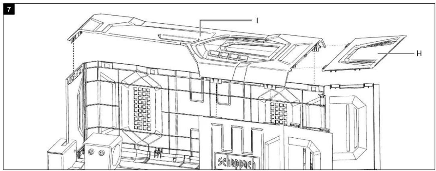
- Connect the holders of the upper flap (H) to the hinge of the upper cover (I)
- Clip the cover (I) into the side covers. (Fig. 7)
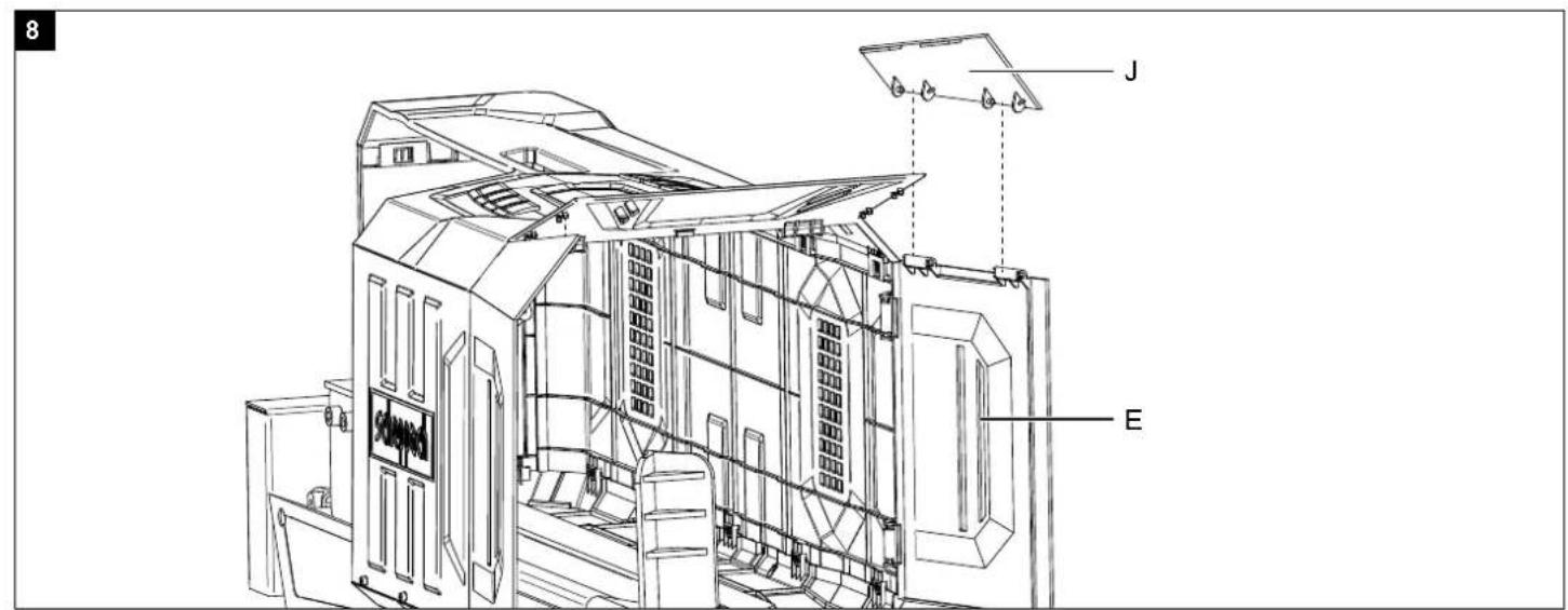
- Attach the flaps (J) to the hinge of the side covers (E).
- Now clip the flaps (J) together with the flap (H). (Fig. 8)
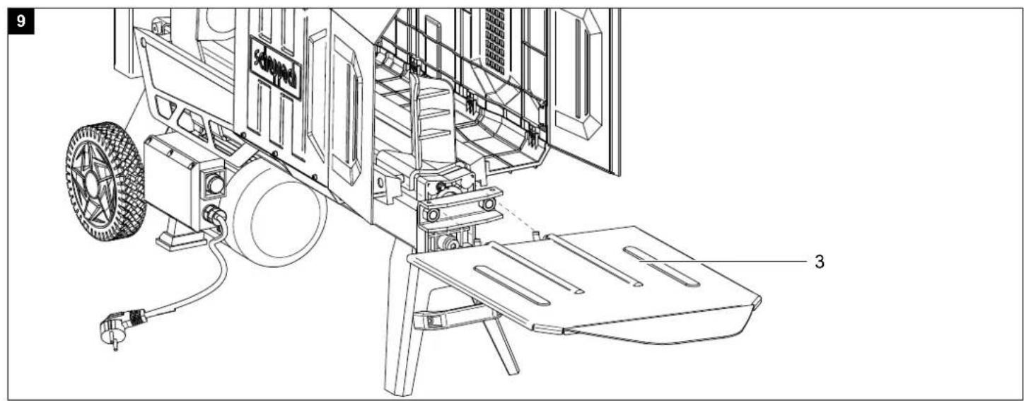
9.5 Fitting the tray table (fig. 9)
- Push the tray table (3) into the holder provided.
ATTENTION!
Always make sure the device is fully assembled before commissioning!
10. Commissioning
Before commissioning, place the splitter on a stable, level and flat workbench so that the splitter actuation button (6) is at a height of 72 - 85 cm.
Make sure that the machine is installed completely and properly. Before each use, always check:
- the connection cables for defective areas (cracks, cuts and the like),
- the machine for possible damage,
• whether all screws are tightened,
• the hydraulic oil for leaks and - the oil level and
- the safety devices
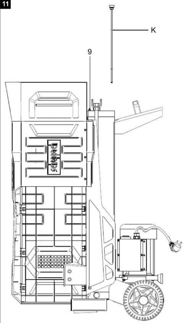
10.1 Check the oil level (Fig. 11)
The hydraulic system is a closed system with an oil tank, oil pump and control valve. Check the oil level regularly before commissioning. An oil level that is too low can damage the oil pump. The oil level must be within the middle mark on the oil dipstick (K). The machine must be level. Screw in the oil dipstick (K) fully, to measure the oil level.
10.2 Bleeder screw (Fig. 11)
Before starting work, it is essential to loosen the bleeder screw (9) by a few turns to ensure air circulation in the oil tank. If it remains tightened while working, the hydraulic movement leads to overpressure which can damage your machine! Before transporting the device, it is essential to tighten this bleed screw (9) to prevent oil leakage.
10.3 Splitting logs
Only split logs that have been sawn off straight. To do this, proceed as follows:
- Place the log to be split straight on the support surface
- Your machine is equipped for two-handed operation – the left hand operates the operating lever (1), the right the release button (6).
- Press the operating lever forwards in the way described and initiate the splitting process by pressing the release button (6).
Releasing one of the control parts leads to the machine stopping immediately. Releasing both control parts causes the pressure plate to retract. If a piece of log to be split cannot be split within 5 seconds, stop the process immediately. The log is probably too hard for the capacity of your machine. Turn the log 90° and try again. Caution: Continuous operation for more than 5 seconds can pose a risk of overheating. You device may become damaged.
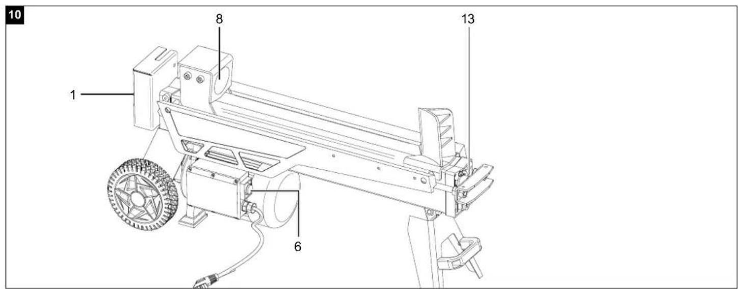
10.3.1 Stroke limitation
(Fig. 10 - Figure without guard! Guard must be fitted when operating the splitter!)
If the log is short, it makes sense to limit the stroke of the pressure plate (8). To do this, press the control handle (1) and the actuating knob (6) and move the pressure plate (8) until just in front of the log.
Now release the actuating knob (6), place the stroke limiting ring (13) against the housing and tighten it. You can then release the control handle (1).
The pressure plate (8) now remains in the selected position.
10.4 Incorrect placement
Always place the log flat on the support surface! It must not slip or be placed at an angle. The riving knife will be overstressed if a splitting process does not take place across the entire cutting edge, but only in the upper area. Never split multiple pieces at the same time! There is a danger that one of the parts may experience uncontrollable acceleration. High danger of injury!
10.5 Wedged logs
Never try to knock wedged logs out of your machine.
This can lead to accidents and damage to the device.
Proceed as follows:
- Allow the pressure plate to move back to the start position.
- Place a wedge under the log
- Trigger a splitting process so that the pressure plate pushes the wedge far below the log to be removed.
- Repeat the above steps with new wedges until the log is pushed up and out of the machine.
11. Electrical connection
The electrical motor installed is connected and ready for operation. The connection complies with the applicable VDE and DIN provisions.
The customer's mains connection as well as the extension cable used must also comply with these regulations.
- The product fulfils the requirements of EN 61000-3-11 and is subject to special connection requirements. This means that use at any freely selectable connection points is not permitted.
- The device can cause temporary voltage fluctuations in unfavourable mains conditions.
- The product is only intended for use at connection points that
a. do not exceed a maximum permissible mains impedance of "Zmax = 0.345 Ω", or
b. have a continuous current-carrying capacity of the mains of at least 100 A per phase. - As the user, you are required to ensure that the connection point at which you wish to operate the product fulfils one of the requirements mentioned, a) or b). If necessary, consult with your energy supplier in this regard.
Damaged electrical connection cable
The insulation on electrical connection cables is often damaged.
This may have the following causes:
- Pressure points, where connection cables are passed through windows or doors.
- Kinks where the connection cable has been improperly fastened or routed.
- Places where the connection cables have been cut due to being driven over.
- Insulation damage due to being ripped out of the wall outlet.
- Cracks due to the insulation ageing.
Such damaged electrical connection cables must not be used and are life-threatening due to the insulation damage.
Check the electrical connection cables for damage regularly. Ensure that the connection cables are disconnected from electrical power when checking for damage.
Electrical connection cables must comply with the applicable VDE and DIN provisions. Only use connection cables with the designation H05VV-F.
The printing of the type designation on the connection cable is mandatory.
For single-phase AC motors, we recommend a fuse rating of C 16A or K 16A for machines with a high starting current (from 3000 watts)!
AC motor 230 V\~ / 50 Hz
Mains voltage 230 V\~ / 50 Hz.
Mains power connection and extension leads must be 3-core = P + N + SL. - (1/N/PE).
Extension cables up to 25m long must have a cross-section of 1.5 mm ^4 .
The mains power connection must be protected with a max. 16 A fuse.
12. Cleaning
Attention!
Disconnect the mains plug before carrying out any cleaning work.
We recommend that you clean the device directly after every use.
Clean the device at regular intervals using a damp cloth and a little soft soap. Do not use any cleaning products or solvents; they could attack the plastic parts of the device. Make sure that no water can penetrate the device interior.
13. Transport
The log splitter is equipped with two wheels for easy transport.
Remove the tray table beforehand (see 9.5).
The machine can be transported on the wheels at an angle. Use the transport handle, lift and pull or push.
14. Storage
Store the device and its accessories in a dark, dry and frost-free place that is inaccessible to children.
The optimum storage temperature lies between 5 and 30 °C.
Store the tool in its original packaging. Cover the tool to protect it from dust or moisture. Store the operating manual with the tool.
15. Maintenance
Attention!
Disconnect the mains plug before carrying out any maintenance work.
Our recommendation to you:
- The splitting blade is a wearing part that must be resharpened if necessary.
- The combined two-hand protective device must remain smooth-running. Lubricate with a few drops of oil as required.
- Keep the support surface clean.
- Lubricate the slide rails with grease.
Check the oil level regularly.
An oil level that is too low will damage the oil pump Regularly check hydraulic connections and screw connections for leaks – retighten if necessary.
When do I change the oil?
Change the oil after 150 working hours.
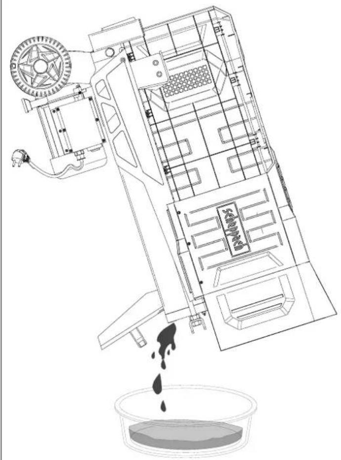
Oil change (Fig. 12)
- Move the log splitter into the start position and pull out the mains plug.
- Remove the tray table beforehand.
- Undo the oil drain screw with oil dipstick (K) and put it to one side. (Fig. 11)
- Place an empty 4.5 l tray next to your machine and raise it as shown in Fig. 12. Wait until all of the used oil has run out. Dispose of the waste oil in an environmentally friendly manner!
- Now turn your machine upside down (Fig. 12) in order to refill approx. 4.2 litres of hydraulic oil.
- Clean the oil drain screw with oil dipstick (K) and screw it back in to the machine that is still in a vertical position. Unscrew it again; there should be an oil film between the notch.
- Now screw the oil drain screw with oil dipstick (K) back in tightly. Then operate the log splitter empty a few times.
- Check the oil level one last time and top up with a little oil if required.
Dispose of the used oil properly at a local used oil collection point. Dumping used oil in the soil or mixing it with waste is prohibited.
We recommend oil from the HLP 32 range.
Connections and repairs
Connections and repair work on the electrical equipment may only be carried out by electricians.
Please provide the following information in the event of any enquiries:
• Type of current for the motor
• Machine data - type plate
• Engine data - type plate
Service information
With this product, it is necessary to note that the following parts are subject to natural or usage-related wear, or that the following parts are required as consumables.
Wearing parts*: Riving knife, hydraulic oil, riving bar guides
* may not be included in the scope of supply!
16. Disposal and recycling

The device is supplied in packaging to avoid transport damages. This packaging is raw material and can thus be used again or can be reintegrated into the raw material cycle.

The device and its accessories are made of different materials, such as metals and plastics. Take defective components to special waste disposal sites. Check with your specialist dealer or municipal administration!
Do not throw old equipment away with household waste!

This symbol indicates that this product must not be disposed of in household waste as per Waste Electrical and Electronic Equipment directive (2012/19/EU) and national laws. This product must be handed over at the intended collection point. This can be done, for example, by returning it when purchasing a similar product or delivering it to an authorised collection point for the recycling of old electrical and electronic devices. Improper handling of waste equipment may have negative consequences for the environment and human health due to potentially hazardous substances that are often contained in electrical and electronic equipment. By disposing of this product properly, you are also contributing to the effective use of natural resources. Information about collection points for old devices can be found at your municipal authority, the local disposal provider, an authorised location for the disposal of old electrical and electronic devices or your waste collection service.
17. Troubleshooting
The following table shows fault symptoms and describes remedial measures in the event of your machine failing to work properly. If you cannot localise and rectify the problem with this, please contact your service workshop.
| Fault Possible cause Remedy | ||
| The engine ends the splitting process automatically | Overvoltage protection device was triggered | Call a qualified electrician |
| Log is not split | Machine loaded incorrectly Insert the log correctly | |
| Size of log exceeds motor capacity Saw logs into a more suitable size | ||
| Riving knife is blunt Grind the riving knife | ||
| Oil leaks Locate the leak, call the dealer | ||
| Pressure plate vibrates, makes noise | Low oil and excess air in the hydraulic system | Check the oil level, top up if necessary, otherwise call the dealer |
| Oil leaks on the cylinder or in other places | Trapped air in the hydraulic system during operation | Loosen the bleeder screw a few turns before use |
| Bleeder screw not tightened before transport | Tighten the bleeder screw firmly before transport | |
| Oil drain screw loose Tighten the oil drain screw firmly | ||
| Oil valve and/or seals defective Call the dealer | ||
Günzburger Straße 69
D-89335 Ichenhausen
Cher client,
Günzburger Straße 69
89335 Ichenhausen, Germania
Egregio cliente,
Günzburger Straße 69
D-89335 Ichenhausen
Vážený zákazníku,
Günzburger Straße 69
D-89335 Ichenhausen
Vážený zákazník,
Günzburger Straße 69
D-89335 Ichenhausen
Austatud klient!
Günzburger Straße 69
D-89335 Ichenhausen
Gerbiamas kliente,
Günzburger Straße 69
Günzburger Straße 69
D-89335 Ichenhausen
Kedves Ügyfelünk!
Günzburger Straße 69
D-89335 Ichenhausen
Spoštovani kupec,
želimo vam veliko veselja in uspeha pri delu z vašo novo napravo.
Napotek:
Günzburger Straße 69
D-89335 Ichenhausen
Poštovani kupci,
Günzburger Straße 69
D-89335 Ichenhausen
Szanowny Kliencie,
CE - Declaration of Conformity
 | |
 | |
| Annex IV Notified Body: Notified Body No.: Certificate No.: | |
Standard references:
EN 55014-1:2017; EN 55014-1:2006/A2:2011; EN 55014-2:2015; EN 55014-2:1997/A2:2008; EN61000-3-2:2014; EN IEC 61000-3-2:2019; EN 61000-3-11:2000; EN IEC 61000-3-11:2019; EN 609-1:2017; EN 60204-1:2018
This declaration of conformity is issued under the sole responsibility of the manufacturer.
The object of the declaration described above fulfils the regulations of the directive 2011/65/EU of the European Parliament and Council from 8th June 2011, on the restriction of the use of certain hazardous substances in electrical and electronic equipment.
Subject to change without notice
Documents registrar: Viktor Härtl
Günzburger Str. 69, D-89335 Ichenhausen
Garantie DE
Apparent defects must be notified within 8 days from the receipt of the goods. Otherwise, the buyer's rights of claim due to such defects are invalidated. We guarantee for our machines in case of proper treatment for the time of the statutory warranty period from delivery in such a way that we replace any machine part free of charge which provably becomes unusable due to faulty material
or defects of fabrication within such period of time. With respect to parts not manufactured by us we only warrant insofar as we are entitled to warranty claims against the upstream suppliers. The costs for the installation of the new parts shall be borne by the buyer. The cancellation of sale on the reduction of purchase price as well as any other claims for damages shall be excluded.