
Bi2 SL SMART S1 - Air-conditioner OLIMPIA SPLENDID - Free user manual and instructions
Find the device manual for free Bi2 SL SMART S1 OLIMPIA SPLENDID in PDF.

| Product type | Fan coil unit for air conditioning and heating |
| Brand | Olimpia Splendid |
| Model | Bi2 SL SMART S1 |
| Dimensions (W × H × D) for size 200 | 759 × 579 × 659 mm |
| Weight (size 200) | 11.5 kg |
| Power supply | 230 V ~ 50 Hz single phase |
| Main functions | Heating, cooling, ventilation (multiple speeds) |
| Motor type | Brushless DC (low consumption) |
| Hydraulic connections | Eurocone 3/4" |
| Maximum working pressure | 10 bar |
| Max. water inlet temperature | 80 °C |
| Min. water inlet temperature | 4 °C |
| Water content of coil (size 200) | 0.47 l |
| Air filter | Washable with water, regular cleaning required |
| Installation types | Wall, floor (vertical) or ceiling (horizontal, for SL) |
| Manufacturer warranty | 24 months (except special conditions) |
| External cleaning | Soft damp cloth, do not use abrasive products |
| Safety | Cut off power before maintenance, grounding mandatory |
| Spare parts | Available through Olimpia Splendid authorized technical service |
| General information | Instruction and installation manual provided; use by children over 8 years under supervision |
Frequently Asked Questions - Bi2 SL SMART S1 OLIMPIA SPLENDID
User questions about Bi2 SL SMART S1 OLIMPIA SPLENDID
0 question about this device. Answer the ones you know or ask your own.
Ask a new question about this device
Download the instructions for your Air-conditioner in PDF format for free! Find your manual Bi2 SL SMART S1 - OLIMPIA SPLENDID and take your electronic device back in hand. On this page are published all the documents necessary for the use of your device. Bi2 SL SMART S1 by OLIMPIA SPLENDID.
USER MANUAL Bi2 SL SMART S1 OLIMPIA SPLENDID
- The appliance may be used by children over 8 years of age and by persons with reduced physical, sensorial or mental capacities, or without the required experience or knowledge, provided they are supervised or have been instructed in the safe use of the appliance and understand the hazards involved.
- Children must not play with the equipment.
- Children must not be allowed to clean the appliance or perform user maintenance without proper supervision.
- Installation, initial start-up and subsequent maintenance, with the exception of the ambient air filter cleaning and washing, must be carried out solely by authorized and qualified personnel.
In any case, as they are built into the system, the compliance of the ventilators/fan coils in the specific installation must be verified and guaranteed by the installer in order to comply with the applicable laws and regulations.
2.9.1 - Dismounting panels 45
2.9.2 - Mounting the condensation discharge device in the horizontal version 45
2.9.3 - Dismantling the heating plate (SLR SMART model only) 45
2.9.4 - Dismantling the exchanger 46
2.14.1 - Extraction of filter cells in the versions with aspiration grill with flaps 47
2.14.2 - Cleaning filtering seats 47
2.15- ENERGYSAVING TIPS 47
3 - TROUBLESHOOTING 48
3.1- TABLE OF ANOMALIES AND REMEDIES 48
POSAL

This symbol on the product or its packaging indicates that the appliance cannot be treated as normal domestic trash, but must be handed in at a collection point for recycling electric and electronic appliances.
Your contribution to the correct disposal of this product protects the environment and the health of your fellow men. Health and the environment are endangered by incorrect disposal.
Further information about the recycling of this product can be obtained from your local town hall, your refuse collection service, or in the store at which you bought the product.
This regulation is valid only in EU member states.
EN-36

OLIMPIA SPLENDID
MAIN INDEX
The main index of this manual is given on page "EN-1"
1 - GENERAL
1.1 - GENERAL INFORMATION
Thank you for choosing an Olimpia Splendid Bi2 cooler-radiator/ cooler-convector for controlling the climate in your home. Please read this instruction use and installation manual carefully before installing and starting up the appliance. Following the indications contained in this manual will ensure that the appliance continues to function perfectly over time. In compliance with European standard 99/44/EEC the manufacturer guaranteed the machine for 24 months from the date of purchase (except for any warranty extensions) against any defects that can be attributed to manufacturing defects. Excluded are all other problems linked to incorrect installation, extraordinary atmospheric events, non-compliant dimensioning or unauthorized interventions.
1.1.1 - Conformity
The OLIMPIA SPLENDID Bi2 cooler-radiator/cooler-convectors conform to the following European Directives:
Low tension directive 2014/35/EU
Electro-magnetic compatibility 2014/30/EU.
In any case, as they are built into the system, the compliance of the ventilators/ fan coils in the specific installation must be verified and guaranteed by the installer in order to comply with the applicable laws and regulations.
1.2 - SYMBOLS
The pictograms in the next chapter provide the necessary information for correct, safe use of the machine in a rapid, unmistakable way.

Index
Paragraphs marked with this symbol contain very important information recommendations, particularly as regards safety.
Failure to comply with them may result in:
- danger of injury to the operators
- loss of the warranty
- refusal of liability by the manufacturer.

GENERIC DANGER
- Signals to the personnel that the operation described could cause physical injury if not performed according to the safety rules.
1.3 - GENERAL WARNINGS
WHEN USING ELECTRICAL EQUIPMENT,
BASIC SAFETY PRECAUTIONS MUST ALWAYS BE FOLLOWED IN ORDER TO REDUCE RISKS OF FIRE, ELECTRIC SHOCKS AND INJURY, INCLUDING THE FOLLOWING:

After unpacking, make sure that all the components are present. If not, contact the OLIMPIA SPLENDID agent who sold the appliance to you.

- OLIMPIA SPLENDID appliances must be installed by an authorised installer who, on completion of the work, will release a declaration of conformity to the client in respect of the laws in force and the indications given by OLIMPIA SPLENDID in the instructions leaflet supplied together with the appliance.

- These appliances have been designed both for conditioning and/or heating environments and must be destined for this use only and compatibly with their performance characteristics.
OLIMPIA SPLENDID accepts no responsibility, either contractual or extra-contractual, for any damage caused to persons, animals of property as a result of incorrect installation, adjustment or maintenance or improper use.

- In case of water leaks, turn the master switch of the system to "OFF" and close the water taps.
As soon as possible, call the OLIMPIA SPLENDID technical service department or else professionally qualified personnel and do not intervene personally on the appliance.

- In the Bi2 installation, inaccessibility to the rear of the appliance must be guaranteed.
In the event this is not guaranteed by the wall or ceiling, it is obligatory to use the rear closure kit available as an accessory.

-
If the appliance is not used for a log period of time, the following operations should be performed:
-
Turn the master switch of the system to "OFF"
-
Close the water taps
-
If there is the risk of freezing, make sure that anti-freeze has been added to the system otherwise empty the system.

- The electrical system must be made in full compliance with the applicable laws and regulations, it must be earthed and have adequate protection against overloads and/or short-circuits. Installation of an omnipolar disconnection switch and suitable electrical protection is advisable on the power line of each appliance installed.

- An excessively high or low temperature (depending on the operating mode) is harmful to the health and wastes energy needlessly.
Avoid prolonged contact with the direct air flow.
EN-38

- Do not leave the room closed for long periods. Periodically open the windows to ensure a correct change of air.

- This instruction leaflet is an integral part of the appliance and consequently must be kept carefully and must ALWAYS accompany the appliance, even when it is passed to a new owner or user or transferred onto another system. If it is lost or damaged, please contact the local OLIMPIA SPLENDID technical service centre.

- All repair or maintenance interventions must be performed by the technical service department or by professionally qualified personnel as foreseen in this booklet. Do not modify or intervene on the appliance as this could create dangerous situations and the manufacturer will not be responsible for any damage caused.
1.4 - FUNDAMENTAL SAFETY RULES

- Remember that some fundamental safety rules should be followed when using a product that uses electricity and water, such as:

- It is forbidden for the appliance to be used by children or unassisted disabled persons.

- It is forbidden to touch the appliance with wet hands or body when barefoot.

- It is forbidden to carry out any cleaning before having disconnected the appliance from the electricity mains supply by turning the system master switch to "OFF".

- It is forbidden to modify the safety or adjustment devices or adjust without authorisation and indications of the manufacturer.

- It is forbidden to pull, cut or knot the electrical cables coming out of the appliance, even if it is disconnected from the mains supply.

- It is forbidden to poke objects or anything else through the inlet or outlet grills.

- It is forbidden to open the doors which access the internal parts of the appliance without first turning the system master switch to "OFF".

- It is forbidden to dispose of or leave in the reach of children the packaging materials which could become a source of danger.

- It is forbidden to climb onto the appliance or rest any object on it.

- The external parts of the appliance can reach temperatures of more than 70^ .

The there are two basic types of Bi2 cooler-radiators/cooler-convectors, SL and SLR, each of which is offered in five sizes with different performances and dimensions.
SL
cooler-convector (suitable for horizontal or vertical installations).
SLR
ventil radiator with radiant plate (suitable for vertical installations).
1.6 - MORE ABOUT THE Bi2 (Fig.1)
A. Supporting structure
in high resistance electro-galvanised steel sheet.
B. Cold water heat exchange battery
in copper pipes and aluminium fins with high efficiency turbulence. eurokonus 3 / 4 type threaded unions in compliance with the new European community standardisation requirements.
The battery is equipped with a special sensor for detecting the water temperature (SL and SLR version).
C. Heating plate;
high efficiency and connected to the hot water battery (SLR version).
The hydraulic unit is fitted with a calostat valve that prevents cold water from entering the plate.
D. Ventilating unit consisting of a tangential fan with unphased blades in synthetic material (extremely quiet) mounted on anti-vibration supports in EPDM, balanced statically and dynamically, and splined directly onto the motor shaft.
E. Low consumption DC brushless electric motor
resin-coated coil mounted on anti-vibration supports in EPDM.
F. Reversible air outlet grill painted
with epoxy powder paint and oven-dried. Its large size ensures high mechanical resistance..
G. condensation collection
basin for vertical installation, made from ABS and easy to remove for cleaning. For horizontal installation of the SL versions, a horizontal condensation collection basin accessory kit is available.
H. Structural back-plate
anti-condensation and high resistance.
I. Detachable front casing
and side plates.
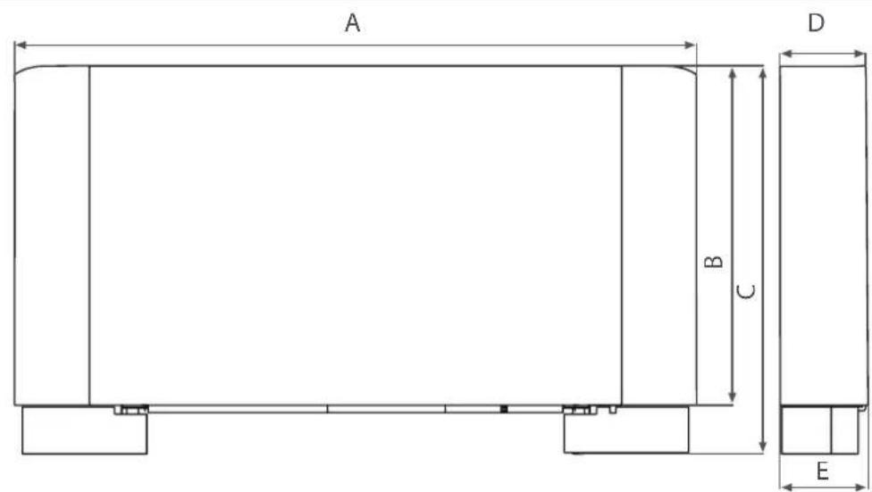
1.7 - OVERALL DIMENSIONS Bi2 (Fig.3)
See figure 3 and refer to the model in question.
3
| SLR SMART 200 400 600 800 1000 | ||||||
| A (mm) | 759 | 959 | 1 | 159 | 135 | 59 1559 |
| B (mm) | 579 | 579 | 579 | 79 | 579 | |
| C (mm) | 659 | 659 | 659 | 659 | 659 | |
| D (mm) | 129 | 129 | 1 | 29 | 129 | 129 |
| E (mm) | 150 | 150 | 150 | 150 | ||
| SL SMART | 200 400 600 | 800 1000 | |
| A (mm) 759 | 959 1159 13 | 59 1559 | |
| B (mm) 579 | 579 579 579 | 579 | |
| C (mm) | 659 659 659 | 659 659 | |
| D (mm) 129 | 129 129 129 | 129 | |
| E (mm) 150 | 150 150 150 | 150 |
1.8 - NOMINAL TECHNICAL FEATURES
Refer to the data for the respective model in the table in figure 4.
A Battery water contents
B Heating plate water content
C Maximum working pressure
D Maximum water inlet temperature
E Minimum inlet water temperature
F Hydraulic fixtures
G Power supply
H Weight SL
I Weight SLR
For information on electrical consumption see the technical features plate on the unit.
4
| 200 | 400 | 600 | 800 | 1000 | ||
| A | I | 0,47 | 0,8 | 1,13 | 1,46 | 1,8 |
| B | I | 0,6 | 0,8 | 1,1 | 1,4 | 1,6 |
| C | bar | 10 | 10 | 10 | 10 | 10 |
| D | °C | 80 | 80 | 80 | 80 | 80 |
| E | °C | 4 | 4 | 4 | 4 | 4 |
| F | " | Eurokonus 3/4 | Eurokonus 3/4 | Eurokonus 3/4 | Eurokonus 3/4 | Eurokonus 3/4 |
| G | V/ph/Hz | 230/1/50 | 230/1/50 | 230/1/50 | 230/1/50 | 230/1/50 |
| H | kg | 11,5 | 13 | 15,5 | 18,5 | 21,5 |
| I | kg | 13,5 | 15,5 | 19,5 | 22,5 | 25,5 |
EN-41
2 - INSTALLATION
2.1 - POSITIONING THE UNIT
Avoid installing the unit in proximity to:
- positions subject to exposure to direct sunlight;
- in proximity to sources of heat;
- in damp areas or places with probable contact with water;
- in places with oil fumes
- places subject to high frequencies.

Figure 5 indicates the minimum mounting distances between the wall-mounted cooler-convect furniture present in the room.
WARNING
failure to apply the indicated standards, which may cause malfunctioning of the equipment, relieves OLIMPIA SPLENDID from any form of warranty and from possible damages caused to people, animals or property.
Make sure that:
a. the wall on which the unit is to be installed is strong enough to support the weight;
b. the part of the wall interested does not have pipes or electric wires passing through;
c. the interested wall is perfectly flat;
d. there is an area free of obstacles which could interfere with the inlet and outlet air flow;
e. the installation wall is preferably an outside perimeter wall to allow the discharge of the condensation outside;
f. in case of ceiling installation the airflow is not directed towards persons.
2.2 - INSTALLATION MODES
The following descriptions of the various mounting phase and the relative designs refer to a version of the machine with fixtures on the left.
The operations for the mounting of machines with fixtures on the right are exactly the same.
Only the images are to be considered as a mirror image.
To ensure that the installation is performed correctly and that the appliance will perform perfectly carefully follow the instructions indicated in this manual. Failure to respect the rules indicated not only can cause malfunctions of the appliance but will also invalidate the warranty and hence OLIMPIA SPLENDID shall not respond for any damage to persons, animals or property.
The appliance must be installed in a position that allows the routine maintenance (filter cleaning) and the extraordinary interventions to be carried out easily, giving access to the air breather valves (battery and plate), reachable from the upper grill on the fixtures side.
2.3 - MINIMUM INSTALLATION DISTANCES
2.4 - SIDE OPENING
- Lift the cover (fig. 6 ref. H) that protects the screw (fig. 6 ref. L) and unscrew it.
- Move the side panel slightly to the right and lift it out (fig. 6 ref. P).
2.5 - VERTICAL FLOOR OR WALL INSTALLATION
When mounting on the floor with support feet, refer to the individual instructions leaflets supplied and the relative manual for the mounting of the feet.

Do not damage the cardboard packaging, the templates needed for correct machine installation are printed on the back and underside of it.
Use the templates on the packaging (cut along the lines indicated), and trace the position of the two fixing brackets on the wall (fig. 7). Use a suitable drill to make the holes with and insert the toggle bolts (2 for each bracket) (fig. 8 ref. A); fix the two brackets (fig. 8 ref. B). Do not over-tighten the screws so that the brackets can be adjusted with a spirit level (fig. 9).
Fully tighten the four screws to block the two brackets.
Check the stability by manually moving the brackets to the right and to the left, up and down.
Mount the unit, checking that it fits correctly onto the brackets and checking that it is stable (fig. 10).
2.6 - HORIZONTAL OR CEILING INSTALLATION (only for SL, SL SMART)
Using the template, trace on the ceiling the position of the two fixing brackets and the two rear screws. Using a suitable drill, make the holes and insert the toggle bolts (2 for each bracket) (fig. 11 ref. A); fix the two brackets (fig. 11 ref. B). Do not over-tighten the screws. Position the machine on the two brackets, keeping it in position and then fix the two screws into the rear toggle bolts (fig. 11 ref. C), one on each side.
Make sure that there is sufficient inclination of the unit towards the drainage pipe to facilitate the water drainage (fig. 11 ref. D).
Fully tighten all 6 fixing screws.
For installation of the SL versions, horizontal condensation collection basin accessory kits are available.
2.7 - HYDRAULIC CONNECTIONS
2.7.1 - Pipeline diameter
The minimum internal diameter that must be respected for the pipelines of the hydraulic connections varies according to the model:
SLR/SL 200 12mm
SLR/SL 400 14mm
SLR/SL 600 16mm
SLR/SL 800 18mm
SLR/SL 1000 020mm

For the position of the pipeline and the wall fixings, refer to the designs as shown in the following sections, based on the specific configuration.
2.7.2 - Connections
The choice and sizing of the hydraulic lines must be made by an expert who must operate according to the rules of good technique and the laws in force.
To make the connections:
- position the hydraulic lines
- tighten the connections using the "spanner and counter spanner" method (fig. 12 ref. B)
- check for any leaks of liquid
coat the connections with insulating material (fig. 12 ref. C).
The hydraulic lines and joints must be thermally insulated.
Avoid partially insulating the pipes.
Do not over-tighten to avoid damaging the insulation.
Use hemp and green paste to seal the threaded connections; the use of Teflon is advised when there is anti-freeze in the hydraulic circuit.
2.8 - CONDENSATION DISCHARGE
The condensation discharge network must be suitably sized (minimum inside pipe diameter 16mm ) and the pipeline positioned so that it keeps a constant inclination, never less than 1% . In the vertical installation, the discharge pipe is connected directly to the discharge tray, positioned at the bottom of the side shoulder underneath the hydraulic fixtures. In a horizontal installation the discharge tube is connected to the one already present on the machine.
For installation of the SL versions in a horizontal position, horizontal condensation collection basin accessory kits are available SL.
If possible, make the condensation liquid flow directly in a gutter or a "rainwater" discharge.
- When discharging directly into the main drains, it is advisable to make a siphon to prevent bad smells returning up the pipe towards the room. The curve of the siphon must be lower than the condensation collection bowl.
- If the condensation needs to be discharged into a container, it must be open to the atmosphere and the tube must not be immersed in water to avoid problems of adhesiveness and counter-pressure that would interfere with the normal outflow.
- If there is a height difference that could interfere with the outflow of the condensation, a pump must be mounted (accessory kit):
- in a vertical installation mount the pump under the lateral drainage tray;
- in a horizontal installation the pump position must be decided according to the specific requirements. In any case, consult the specific instructions in the condensation discharge pump kit.

However, on completion of the installation it is advisable to check the correct outflow of the condensation liquid by slowly pouring about 12 I of water into the collection tray in about 5-10 minutes.
2.8.1 - Mounting the condensation discharge device in the vertical version
Connect to the condensation collection tray discharge union (fig. 13 ref. A) a pipe for the outflow of the liquid (fig. 13 ref. B) blocking it adequately. Check that the drip-collector extension (fig. 13 ref. C) is present and correctly installed.
2.8.2 - Mounting the condensation discharge device in the horizontal version
To mount the horizontal bowl on the SL versions refer to the instructions in the relative optional kit.
Below the side corresponding to the condensate drain tube outlet, cut the pre-cut area (fig. 14 ref. A).
- Refit the side panel.
EN-44

N.B. for the horizontal installation carefully note the following precautions:
- make sure that the machine is installed perfectly level or with a slight inclination towards the condensation discharge;
- insulate carefully the inflow and outflow pipes up to the machine union to prevent any drops of condensation outside the same collection bowl;
- insulate the bowl condensation discharge pipe along all of its length.
2.9 - FIXTURE ROTATION
The operations described and the relative images refer to a machine with fixtures on the left on which the fixtures on the right side must be rotated.
If there is a machine available with right side fixtures that require rotation to the left, the sequence of the operations is the same, only the images are a mirror image.
To connect the motor to the control kit, use the special cabling (optional).
2.9.1 - Dismounting panels
- Lift the cover (fig. 15 ref. H) that protects the screw (fig. 15 ref. L) and unscrew it.
- Move the side panel slightly to the right and lift it out (fig. 15 ref. P).
- Remove the air filters on the lower side (fig. 16 ref. A);
- Undo the screws (fig. 16 ref. B) that secure the front panel (fig. 16 ref. C) and remove by pulling it out from the lower hook (fig. 16 ref. M);
- Remove the battery upper insulation (fig. 16 ref. D);
Unscrew the top inlet connector (fig. 17 ref. A) - Unscrew the bottom outlet connector (fig. 17 ref. B)
Take out the plate with the heating coil (fig. 17 ref. C).
2.9.2 - Dismantling the heating plate (only for SLR SMART)
- Dismount all the collector units (fig. 18 ref. A)
2.9.3 - Dismounting control panel (if present)
Position the system master switch to OFF.
- Remove the door giving access to the collector units (fig. 19 ref. A) by undoing the fixing screw (fig. 19 ref. B).
- Dismount the control panel (fig. 19 ref. C) unscrewing the two fixing screws (fig. 19 ref. D) and relative electrical box.
- Unplug the connectors of the electrical connections.
- Remove the cables inside the machine and re-insert them from the opposite side.
- For the motor connection, use the special cable for right hand fixtures, available as an accessory.
- Invert the mounting positions of the door (fig. 19 ref. A) with the control panel (fig. 19 ref. C) and remount them in their respective positions.
- Dismount the condensation collection tray (fig. 19ref. F) and remount it on the opposite side with the relative fixing screws (fig. 19 ref. G).
- Remove the control E and reassemble it from the opposite side in the respective position with the relative screws
2.9.4. Dismantling the exchanger
- Loosen the four screws that fix the exchanger (fig. 20 ref. A);
remove the battery water probe;
remove the exchanger (fig. 20 ref. B); - remove the drip-collector extension from the central tray (fig. 20 ref. C);
- on the opposite side remove the plug on the condensation evacuation hole (fig. 20 ref. D);
- loosen the central condensation collection tray fixing screw (fig. 20 ref. E), move the tray and rest it on the opposite side so that the fixture mouth for the drip-collector extension comes out of the structure, and block the tray with the screw previously removed;
- re-insert the drip-collector extension and the plug on the opposite side;
- open the pre-cut hexagonal holes on the right side insulation and close with insulation the hexagonal holes on the left shoulder;
- rotate the exchanger moving the fixtures to the opposite side, and reinsert it on the machine (fig. 21);
- tighten all the fixing screws of the exchanger (fig. 22ref. A).
When all the operations described have been completed, remount all the components dismounted previously following the dismounting operations in the opposite order.
When starting up the system, make sure that the hydraulic unit lockshield is open. If there is no electric power and the thermo-valve has already been powered use the special cap to press the valve stopper to open it.
2.11 - EVACUATING AIR WHILE FILLING THE SYSTEM
- Open all the system interception devices (manual or automatic);
- Start the filling by slowly opening the system water filling tap;
- For the SL installed in a vertical position, take a screwdriver and act on the highest breather of the battery (fig. 23 ref. A);
- For SLR models with heating plate use a screwdriver to remove the battery side breather (fig. 23 ref. A) and the manual breather of the heating plate (fig. 24 ref. A).
- When water starts coming out of the breather valves of the appliance, close them and continue filling until reaching the nominal value for the system.
Check the hydraulic seal of the gaskets.
It is advisable to repeat these operations after the appliance has been running for a few hours and periodically check the pressure of the system.
2.12 - MAINTENANCE
Routine maintenance is indispensable to keep the Bi2 cooler-convector in perfect working condition, safe and reliable over the years. This can be done every six months for some interventions and annually for others, by the Technical Service Assistance, technically authorised and prepared, using always original spare parts.
2.13 - CLEANING THE OUTSIDE

Before every cleaning and maintenance intervention, disconnect the appliance from the mains by switching off the master switch.
When necessary, clean the outer surfaces of the Bi2 cooler-convector with a soft cloth damp cloth (fig. 25).

Do not use abrasive sponges or abrasive or corrosive detergents to avoid damaging the painted surfaces.
2.14 - CLEANING AIR SUCTION FILTER
The air filters must be checked at regular intervals and cleaned when necessary, and in any event whenever recommended by the electronic controls installed (if present). The frequency with which filters are cleaned will depend on specific machine running conditions. To clean the air filters, proceed as described in the following sections.
2.14.1 - Taking out filter cells
- take hold of the tab on the filter (fig. 26 ref. A) and by pressing lightly towards the rear wall snap the internal tab out of its fastening (fig. 26 ref. B):
- twist the filter slightly (fig. 26 ref. C);
- pull the filter from its seat (fig. 26 ref. D).
N.B. the number of filters present depends on the size of the machine.
2.14.2 - Cleaning filtering seats
- Suck up the powder with a vacuum cleaner (fig. 27 ref. A).
- Wash the filter (fig. 27 ref. B) with running water without using detergents or solvents, and leave to dry.
- Refit the filter to the cooler-convector (fig. 28 ref. A), taking care to insert the lower flap (fig. 28 ref. B) into its seat (fig. 28 ref. C), while the front one (fig. 28 ref. D) must be resting up against the internal flap on the front plate (fig. 28 ref. E).

It is forbidden to use the unit without the net filters.
2.15 - ENERGY SAVING TIPS
Always keep the filters clean;
- when far possible, keep the doors and windows closed in the room being conditioned;
- limit where possible the effect of direct sun rays in the rooms being conditioned (use curtains, shutters etc.)

In case of water leaks or anomalous functioning immediately cut off the power supply and close the water taps.

Should one of the following anomalies occur, contact an authorised service centre or an authorised qualified person, but do not intervene personally.
- The front heating plate does not reach a uniform temperature during heating.
The ventilation does not activate even if there is hot or cold water in the hydraulic circuit. - The appliance leaks water during the heating function.
The appliance leaks water only during the cooling function. - The appliance makes an excessive noise.
There are formations of dew on the front panel.
3.1 - TABLE OF ANOMALIES AND REMEDIES
Do not try to repair the equipment by yourself.
If the problem has not been solved, please contact your local retailer or the closest assistance service.
| MALFUNCTION | CAUSE | SOLUTION |
| The front heating plate does not reach a uniform temperature during heating. | - Air present in the inner circuit of the appliance. | - Release the air several times (see sect. 2.11). |
| A delayed activation of the ventilation respect to the new temperature or function settings. | - The circuit valve needs some time to open and as a result the hot or cold water takes time to circulate in the appliance. | - Wait for 2 or 3 minutes to open the circuit valve. |
| The ventilation speed increases or decreases automatically. | - The electronic control adjusts the comfort level regularly. | - Wait for the temperature adjustment or in case of necessity select the silent function. |
| The appliance does not activate the ventilation. | - No hot or cold water in the system. | - Check that the water boiler or cooler are functioning correctly. |
| The ventilation does not activate even if there is hot or cold water in the hydraulic circuit. | - The hydraulic valve remains closed. | - Dismount the valve body and check if the water circulation is restored. - Check the working efficiency of the valve by powering it separately with 220V. If it activates the problem could be the electronic control. - Check the windings of the motor and the free rotation of the fan. >>>> |
| - the fan motor is blocked or burnt out. |
EN-48
| - the electrical connections are not correct. | - Check the electrical connections. | |
| The appliance leaks water during the heating function. | - Leaks in the hydraulic connections of the system. - Leaks in the valve unit. | - Check the leak and fully tighten the connections. - Check the state of the gaskets. |
| There are formations of dew on the front panel. | - The thermostatic valve built into the connection unit between the plate and the battery does not close the flow. - Thermal insulation unstuck. | - Replace the union that joins the thermostatic valve to the water inlet upper unit. - Check the correct positioning of the thermo-acoustic insulation paying attention to that in the front above the finned battery. |
| There are drops of water on the air outlet grill. | - In situations of high humidity (>60%) condensation could form, especially at the minimum ventilation speeds. | - As soon as the humidity starts falling the phenomenon disappears. In any case the presence of a few drops of water in the appliance does not indicate a malfunction. |
| The appliance leaks water only during the cooling function. | - The condensation bowl is blocked. - The condensation discharge does not need an inclination for correct drainage. - The connection pipes and the valve unit are not insulated well. | - Slowly pour a bottle of water in the low part of the battery to check the drainage; if necessary, clean the bowl and/or increase the inclination of the drainage pipe. - Check the insulation of the pipes. |
| The appliance makes a strange noise. | - The fan touches the structure. - The fan is unbalanced. | - Check for any interference by manually rotating the fan. - The unbalancing causes excessive vibrations of the machine; replace the fan. |
SOMMAIRE GENÉRAL
1 - GENERALITES 53
1.1 - INFORMATIONS GENERALES 53
1.1.1 Conformité 53
1.2 - SYMBOLES 53
1.3 - AVENTISSEMENT GENERAUX 54
1.4 - REGLES FONDAMENTALES DE SECURITE 55
1.5 - GAMME DE PRODUITS 56
1.6- DECOUVRONS LE Bi2 56
1.7 - DIMENSIONS HORS TOUT Bi2 57
1.8 - CHARACTERISTIQUES TECHNIQUES NOMINALES VERSION Bi2 57
2- INSTALLATION 58
2.1- MISE EN PLACE DE L'UNITE 58
2.2- MODALITES D'INSTALLATION 58
2.3 - DISTANCES MINIMUM D'INSTALLATION 58
2.4 - OUVERTURE FLANCS 58
2.5 - INSTALLATION MURALE OU AU SOL VERTICALE 59
2.6 - INSTALLATION AU PLAFOND OU HORIZONTALE (uniquement pour modèle SL SMART)......59
2.7 - BRANCHEMENTS HYDRAULIQUES 59
2.7.1 -Diametre tubes 59
2.7.2 - Branchements 60
2.8 - EVACUATION DES CONDENSATS 60
E. Motor electrico brushless DC
2.8- CONDENSAFVOER 124
1.3 - ALGEMENE WAARSCHUWINGEN
ALS ELEKTRISCHE APPARATUUR WORDT GEBRUIKT,MOETEN DE BASISVEILIGHEIDSVOORSCHRIFTEN STEEDS WORDEN GEVOLGD OM HET RISICO OP BRAND, ELEKTRISCHE SCHOKKEN EN ONGEVALLEN TE BEPERKEN, INCLUSIEF HET VOLGENDE:

1.5 - PRODUCTENGAMMA
- Demonteer alle collectorunits (afb. 18 ref. A).