
HONBQT3518E - Refrigerator HOOVER - Free user manual and instructions
Find the device manual for free HONBQT3518E HOOVER in PDF.
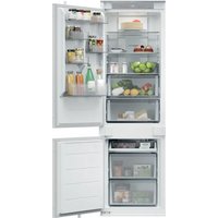


| Product Type | Built-in Refrigerator |
| Brand | Hoover |
| Model | HONBQT3518E |
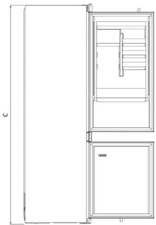
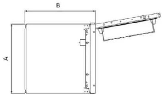
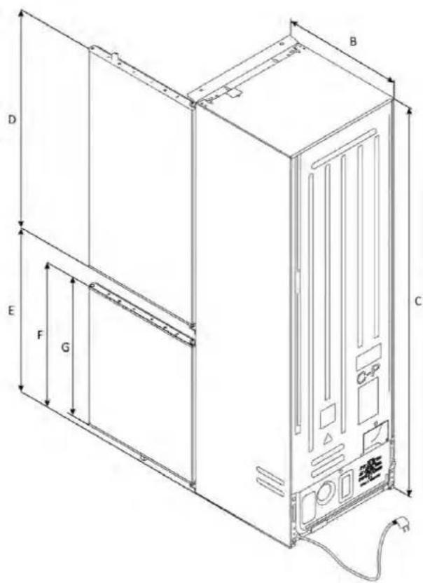
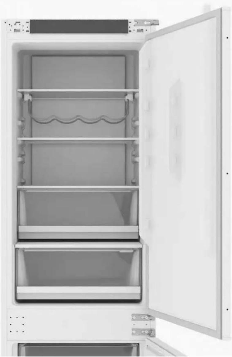
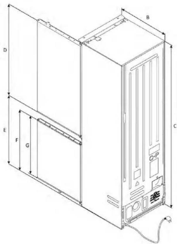
| Dimensions (H x W x D) | 1935 x 540 x 550 mm |
| Climate Class | SN, N, ST, T (10°C to 43°C) |
| Supply Voltage | 220-240 V / 50 Hz |
| Number of Doors | 1 |
| Door Reversibility | Yes, reversible |
| Installation Type | Built-in (integrated) |
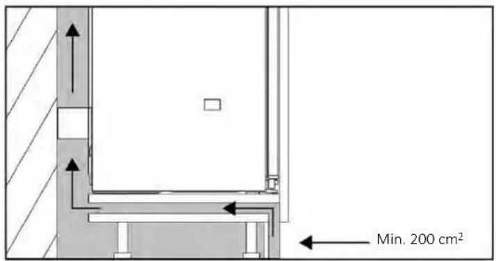
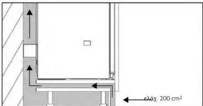
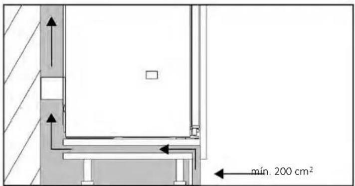
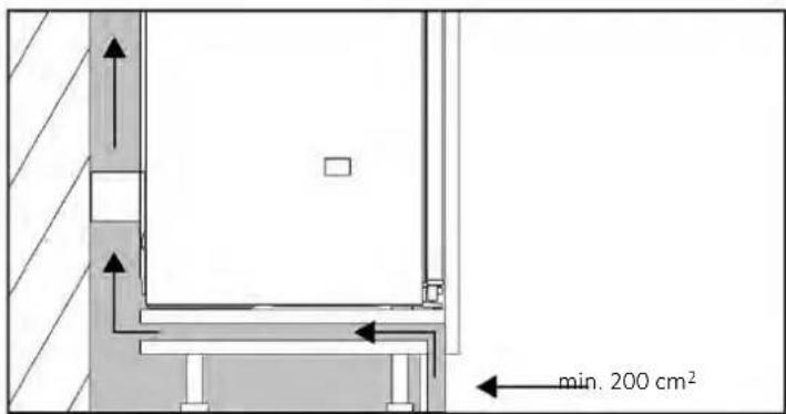
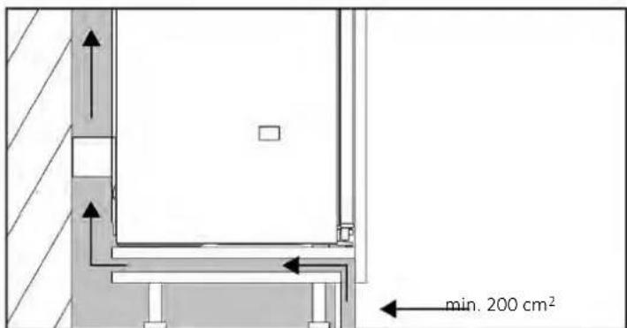
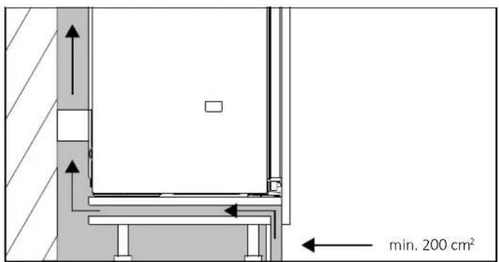
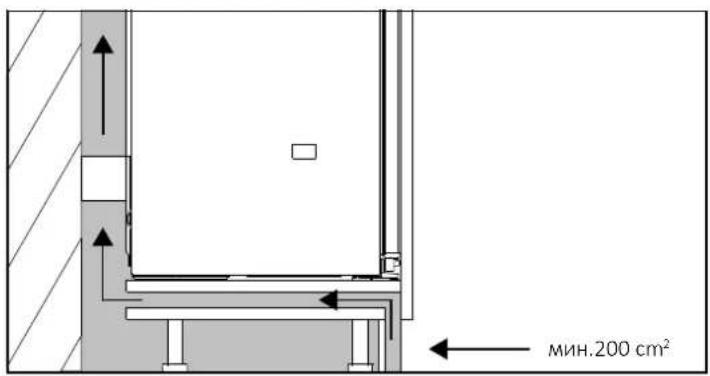
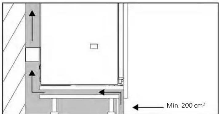
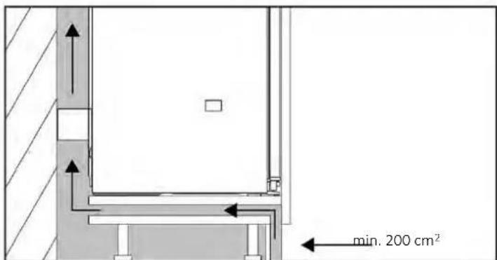
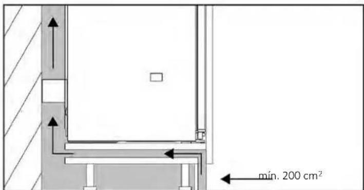
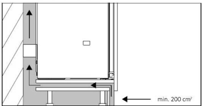
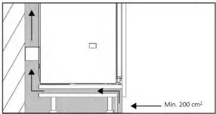
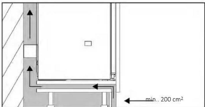
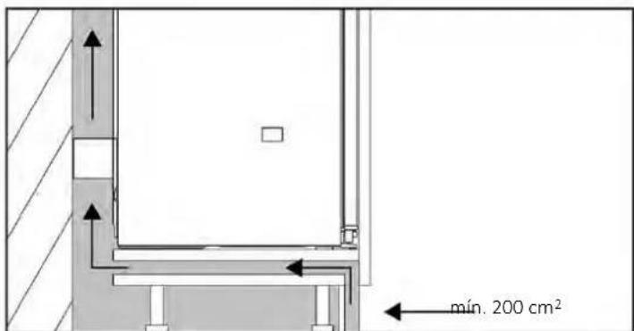
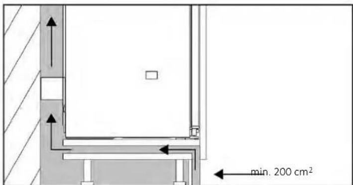
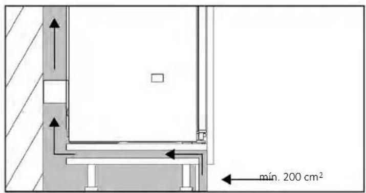
| Required Ventilation | Minimum ventilation opening of 200 cm² |
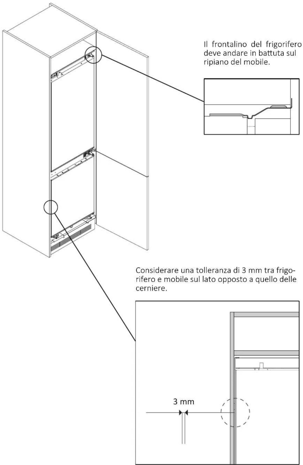
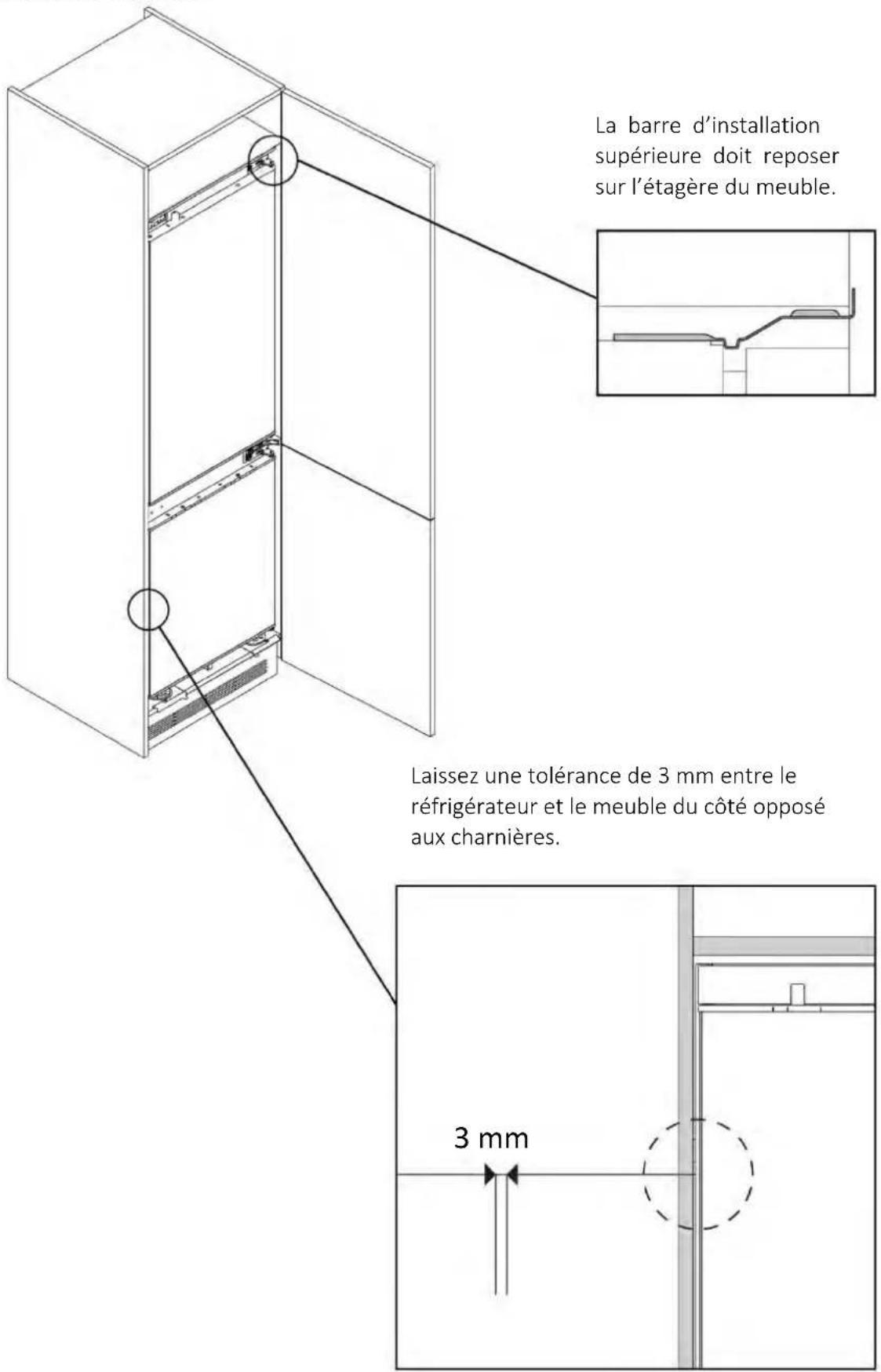
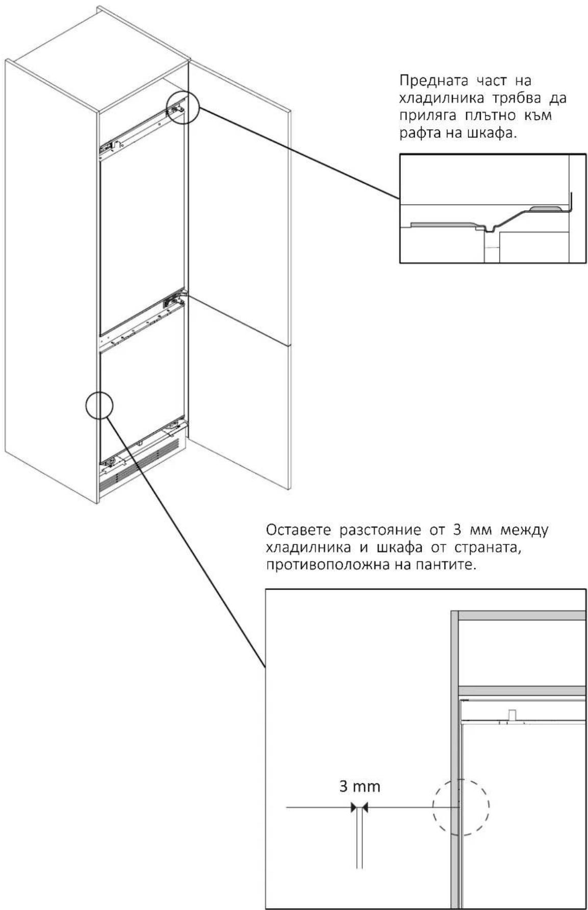
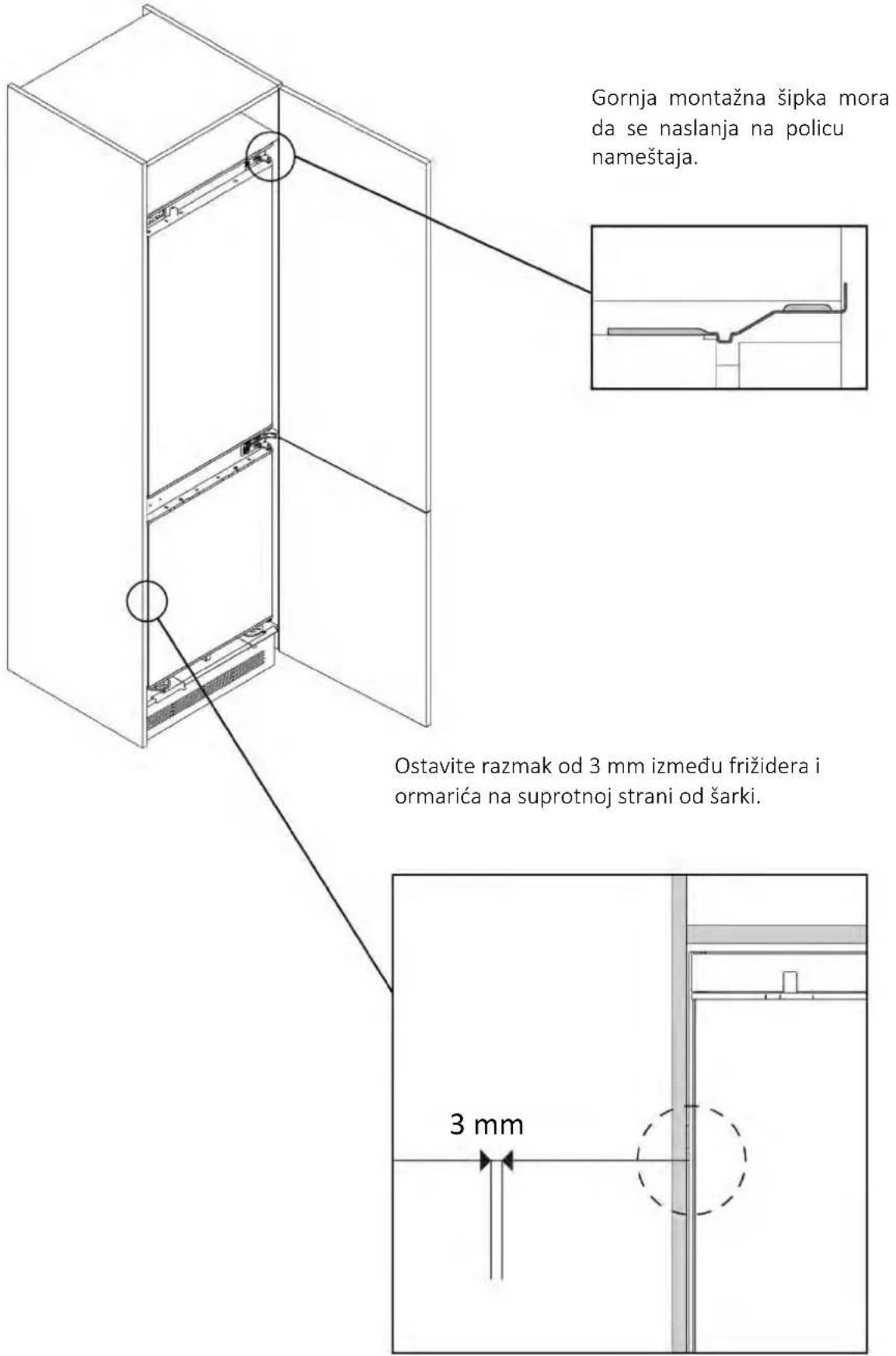
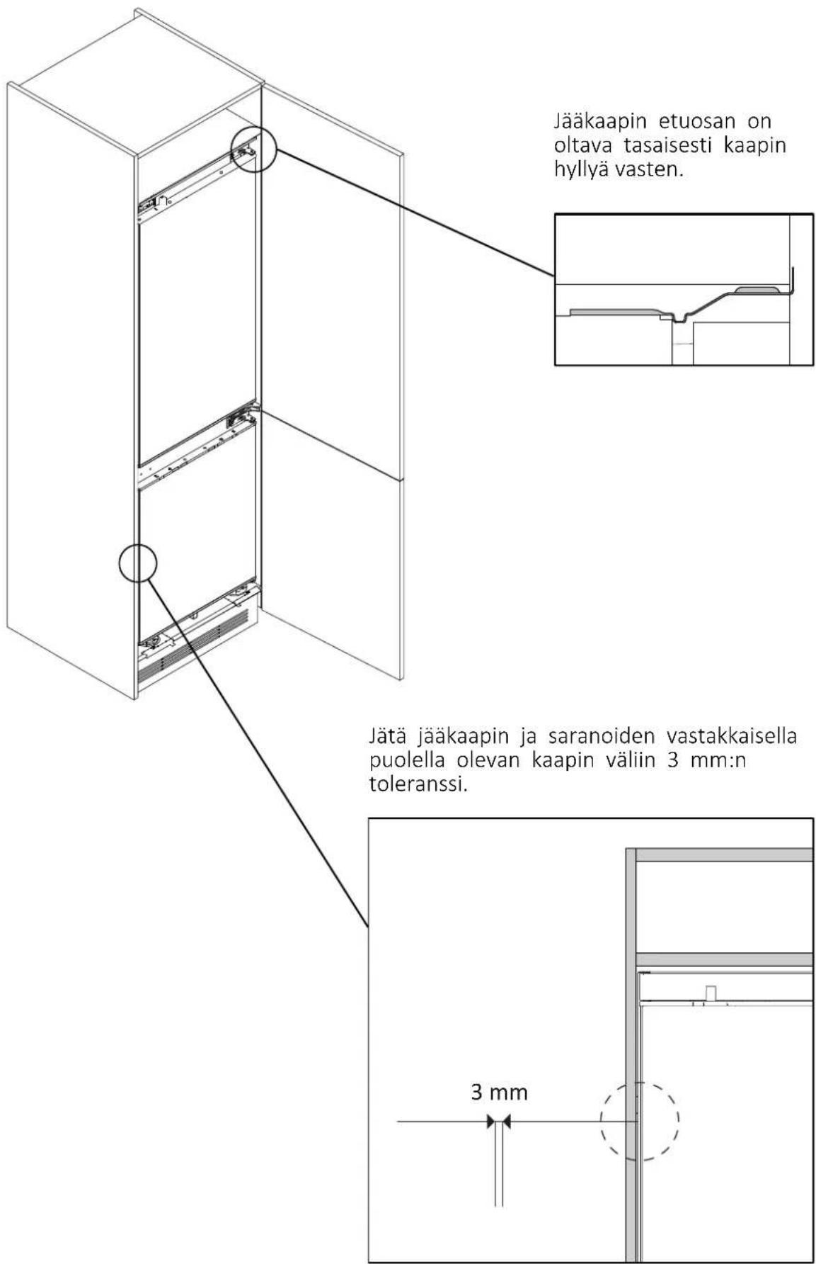
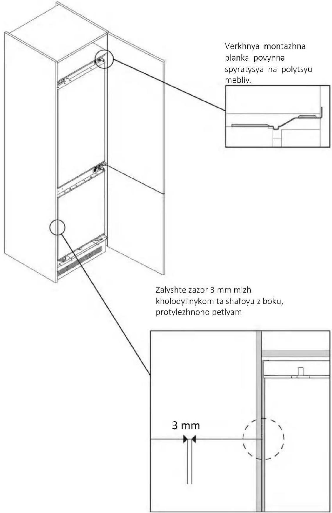
| Safety Distance to Wall | 3 mm between appliance and cabinet on hinge side |
| Power Cord Length | 2270 mm |
| Supplied Accessories | Screws, spacers, seals, covers, brackets, etc. |
| Net Weight | Not specified (estimated 70 kg) |
| Energy Class | Not specified |
Frequently Asked Questions - HONBQT3518E HOOVER
User questions about HONBQT3518E HOOVER
0 question about this device. Answer the ones you know or ask your own.
Ask a new question about this device
Download the instructions for your Refrigerator in PDF format for free! Find your manual HONBQT3518E - HOOVER and take your electronic device back in hand. On this page are published all the documents necessary for the use of your device. HONBQT3518E by HOOVER.
USER MANUAL HONBQT3518E HOOVER
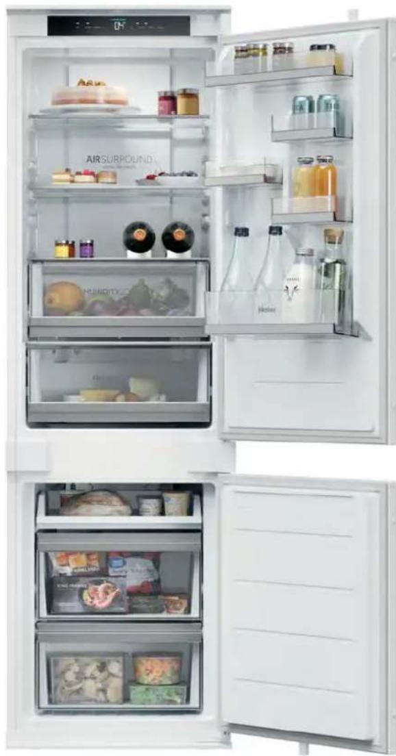
WELCOME
This installation manual is designed for kitchen manufacturers who will deal with these products. To ensure safety and get the best results, please read this manual carefully, including the safety instructions, and keep it for future reference. Before proceeding with the installation, take note of the serial number, as you may need it in case of repairs. Check for any damage during transport and consult a technician when in doubt before using. Always keep all packing material away from children.
NOTE: Features, pictures in the manual and product accessories may vary depending on the model purchased.
Index
1 Safety warnings for installation p.4 2 Where to install the product p.5 3 Refrigerator dimensions p.6 4 Installation tools p.8 5 Cabinet dimensions p.8
5.1 Precautions
5.2 Dimensions
6 Cabinet installation and ventilation p.10
6.1 Installation in column
7 Installation video step by step p.11
8 Change the direction of door opening p.12
8.1 Unlocking the doors
8.2 Removing the bottom screw
8.3 Hinges inversion
8.4 Attaching the bottom screw on the opposite side of the refrigerator
9 Installation instructions for the refrigerator p.14
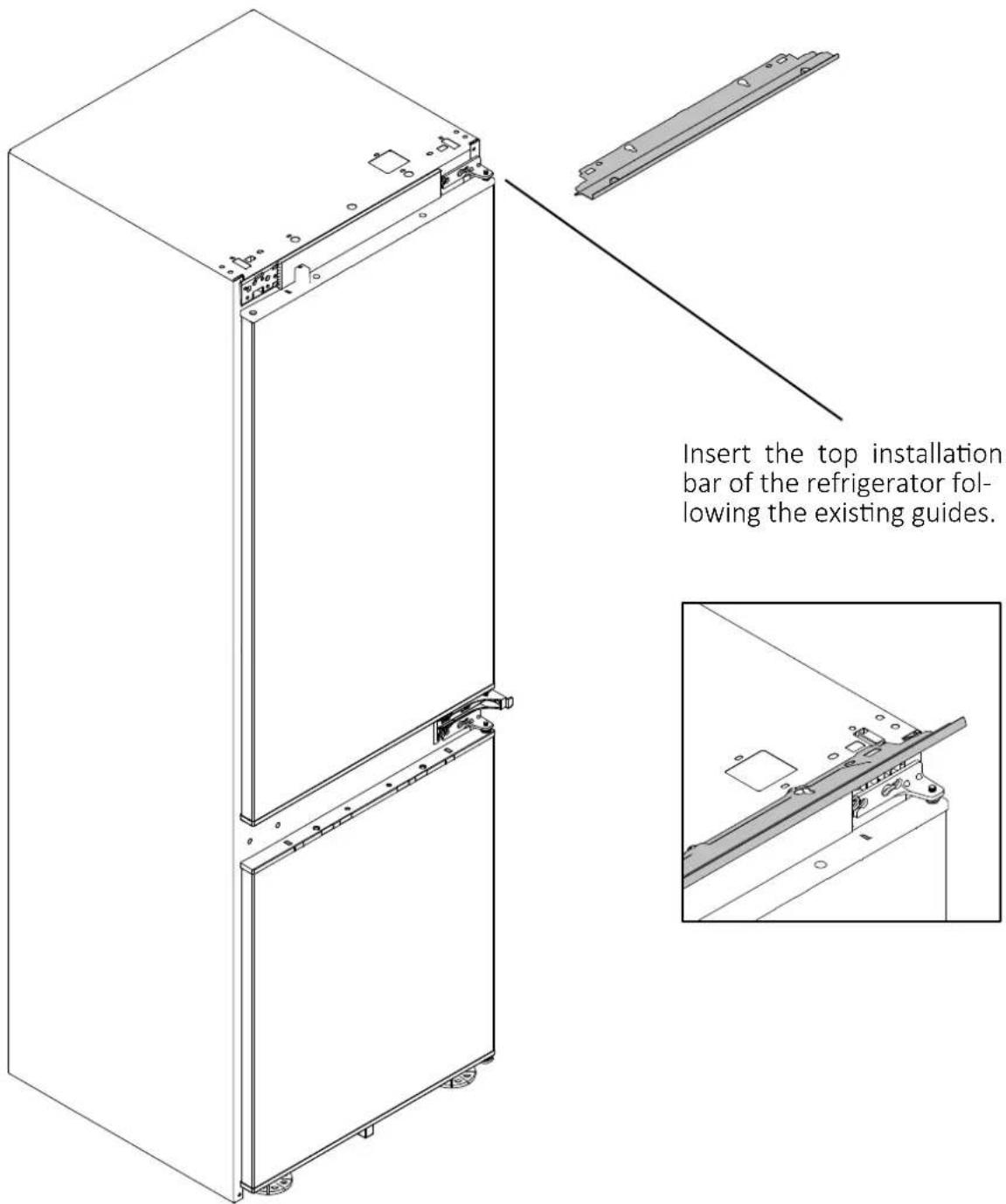
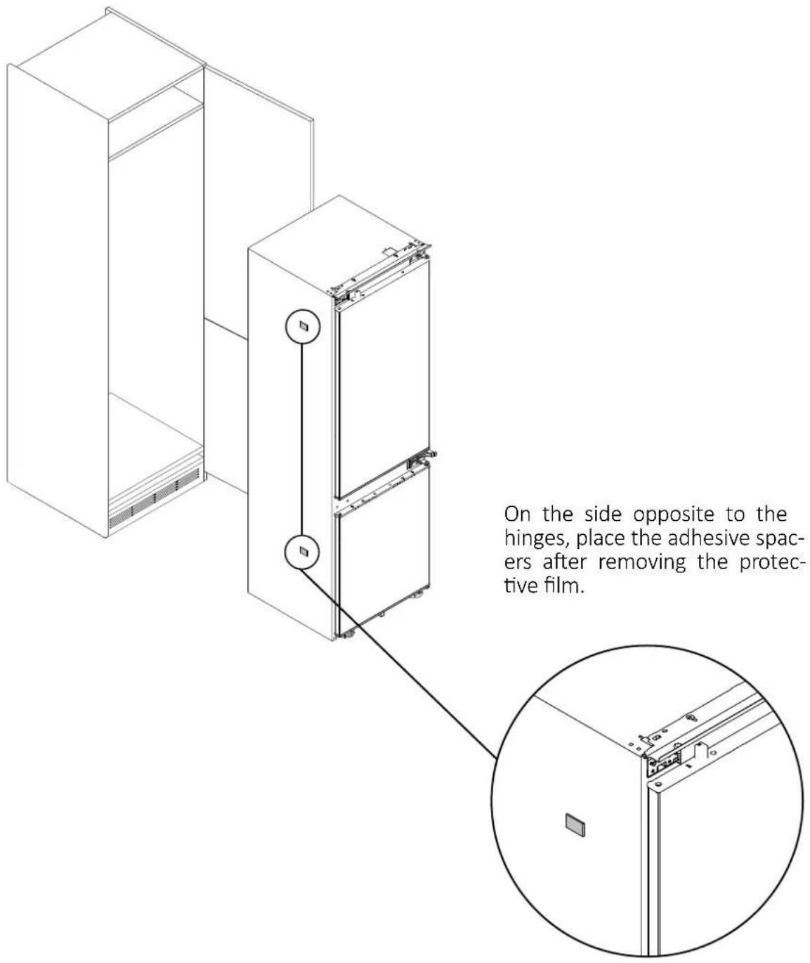
9.1 Applying the top installation bar of the refrigerator 9.2 Applying the adhesive spacers on the side of the refrigerator 9.3 Centering the refrigerator feet 9.4 Built-in installation 9.5 Securing the refrigerator feet 9.6 Mounting the central brackets and covers 9.7 Mounting the bottom covers 9.8 Applying the gaskets on the side of the refrigerator 9.9 Mounting the top covers and securing the refrigerator to the upper shelf 9.10 Attaching the sliding hinges to the cabinet door
index
10 Connection to the mains p.28
10.1 Warnings
10.2 Other advices
11 Delivery to the user p.30
12 Disassemble the product p.30
Observe these directions before beginning the installation of the product. Please observe the following guidelines before starting the installation of the product. Your safety is very important to us. Read these instructions carefully before using the product.
- The installation must be carried out by a qualified technician who is familiar with and adheres to the applicable laws in the country of installation and the manufacturer's instructions;
- If assistance from the manufacturer is required to rectify faults resulting from incorrect installation, such assistance is not covered by the warranty;
- Remove the packaging material before operating the appliance;
- After unpacking the product, check that it is not damaged. In case of any issues, contact the service center before proceeding with installation and do not connect it to the power supply;
- A damaged product can cause a short circuit, electric shock, fire hazard, and other dangers;
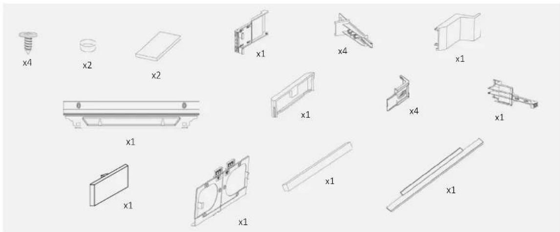
- Check for any accessories or supplementary materials (bags with screws, documents, brochures, etc.) in the packaging and, if present, remove and store them;
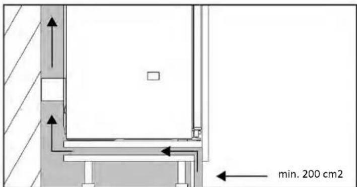
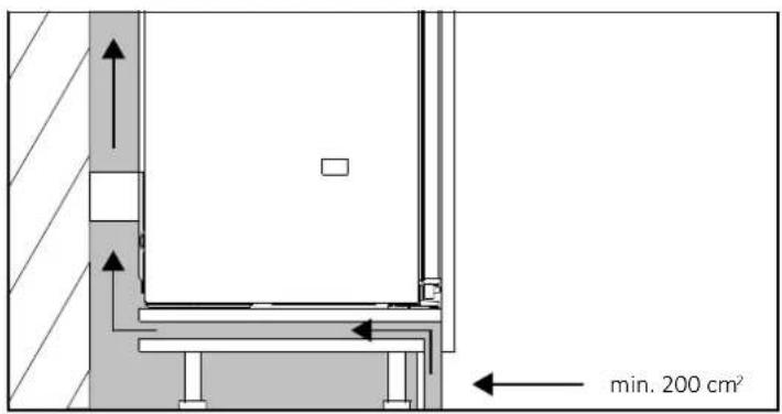
- Before installing the appliance, ensure that ventilation is sufficient to allow the proper circulation of fresh air needed for cooling and protecting the internal components. Depending on the type of setup, create the specified openings as illustrated;
- If manufacturer assistance is needed to rectify any faults due to incorrect installation, such assistance is not covered by the warranty. Follow the installation instructions provided for qualified personnel;
- Incorrect installation can cause damage or injury to people, animals, or property. The manufacturer cannot be held responsible for such damage or injury;
- Safe usage is guaranteed only if the installation has been carried out correctly according to these instructions. In case of damage due to incorrect installation, the responsibility lies with the installer;
- It is recommended to wear protective gloves during installation to avoid injury from cuts;
- The warranty does not cover damage caused by incorrect installation;
- In case of incorrect installation, tampering with the appliance, or non-compliant connection, the product warranty becomes invalid;
- After installation, the power cord must not come into contact with moving parts of kitchen components (e.g., a drawer) and must not be subjected to mechanical stress;
- This product requires constant ventilation during use. Do not cover the air vents;
- Upon completion of the installation, the technician must ensure that the product has been installed correctly.
Important warnings
- Do not install the appliance in areas exposed to direct sunlight to avoid altering the product's performance; • Install and use this product in an enclosed, covered, dry, and well-ventilated environment;
- Do not install the product in outdoor areas exposed to weather elements; • Install the product near an electrical outlet;
- Keep the product away from sources of flames; • Install the appliance on a flat surface, in an area suitable for its size and use;
- Clean the appliance with water and a mild detergent, and dry it with a soft cloth; • The appliance is heavy; at least two people are required to move it;
- After installation, allow the refrigerator to rest for at least 4 hours before turning it on to let the compressor oil settle.
This product is intended solely for installation in domestic or similar environments, such as:
- Kitchen areas intended for staff in shops, offices, and other working environments;
- Spaces available to staff and customers in hotels, motels, and other residential-type environments; • Beauty farms, Bed & Breakfasts (B&B);
- For catering services and similar applications, excluding retail sales.
Install this product in a location where the ambient temperature is not lower or higher than the operating temperature indicated on the product label: otherwise, the appliance will not function correctly.
- Extended temperate (SN): "This appliance is intended for use in ambient temperatures ranging from 10°C to 32°C";
- Temperate (N): "This appliance is intended for use in ambient temperatures ranging from 16°C to 32°C";
- Subtropical (ST): "This appliance is intended for use in ambient temperatures ranging from 16°C to 38°C";
- Tropical (T): "This appliance is intended for use in ambient temperatures ranging from 16°C to 43°C."
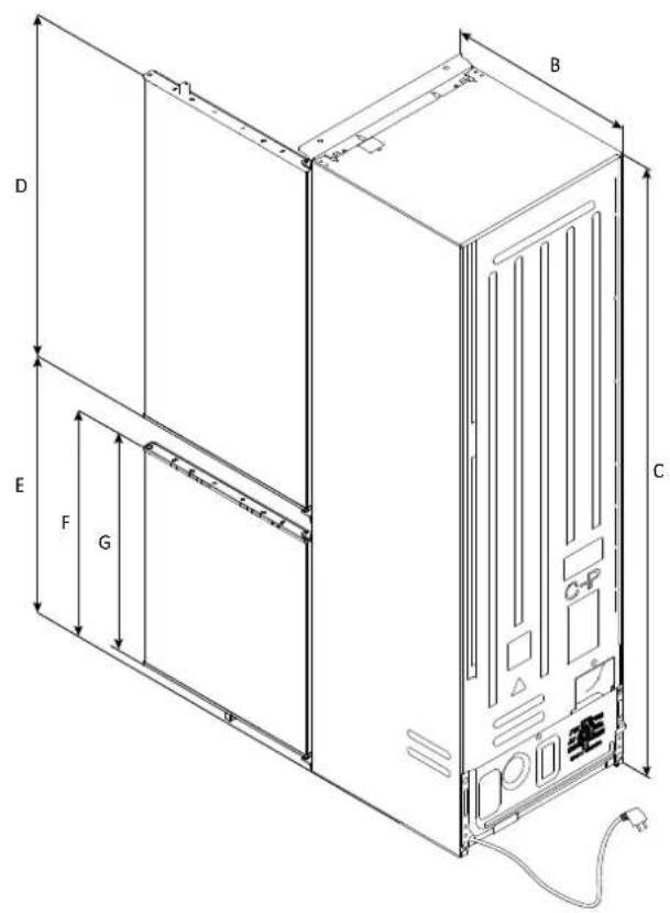
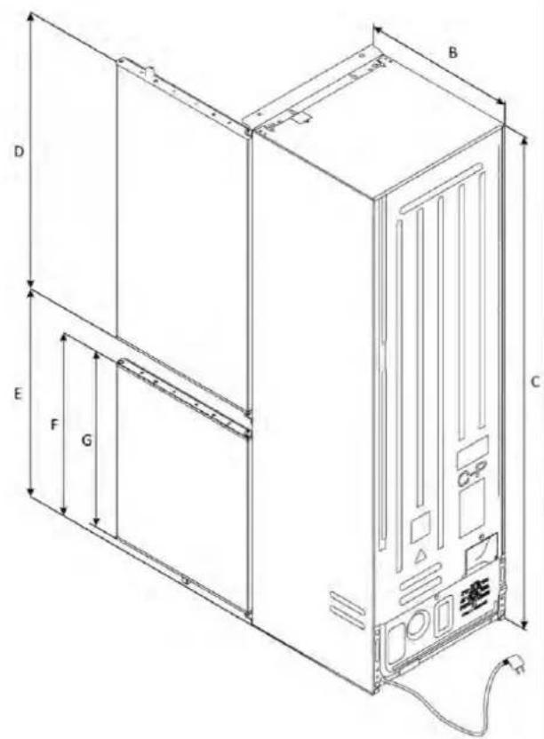
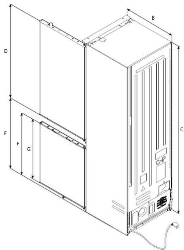
Dimensions in mm
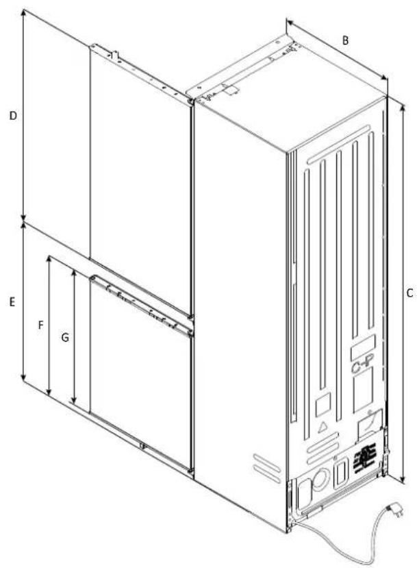
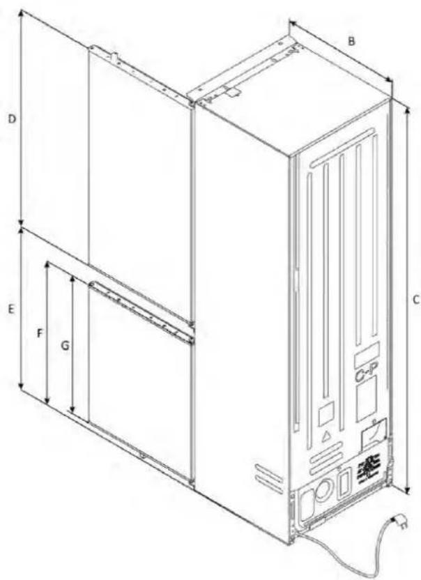
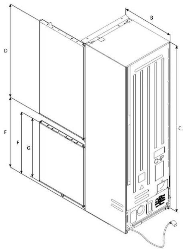
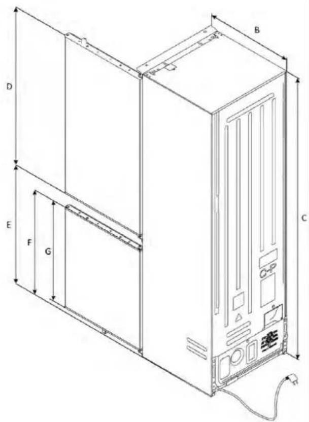
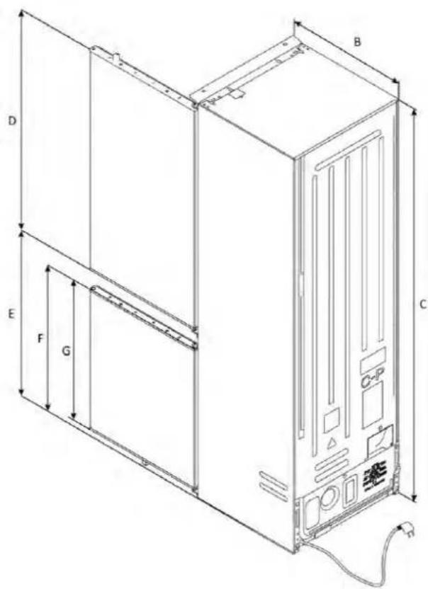
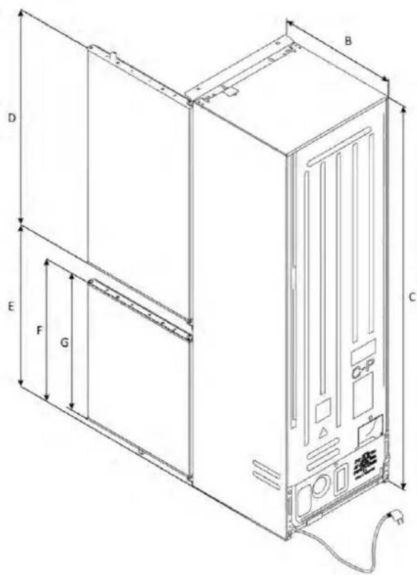
Front axonometric view Rear axonometric view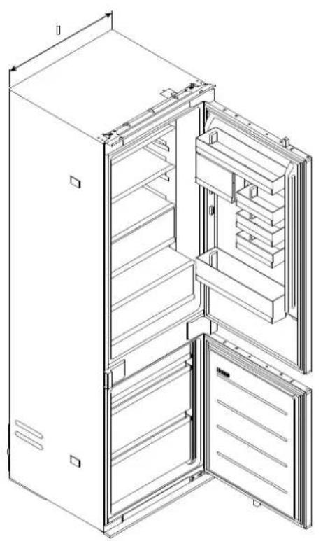
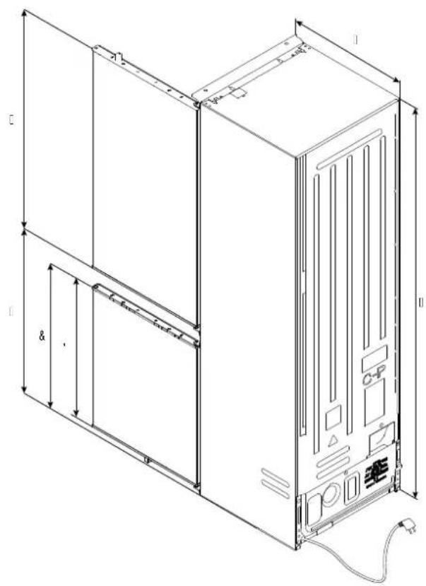
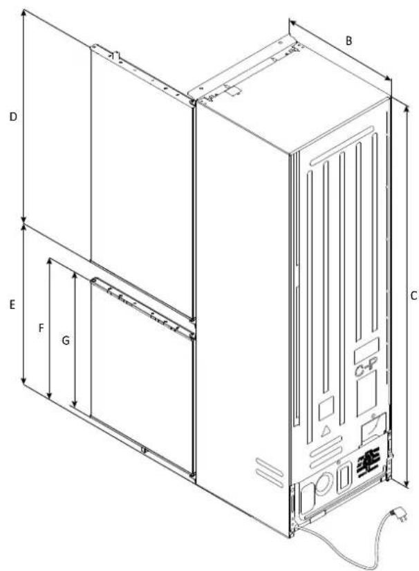
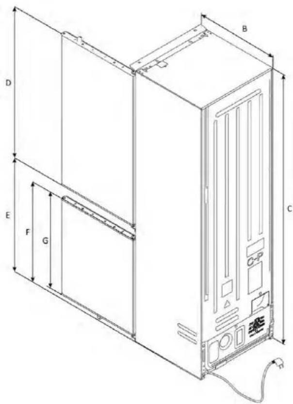
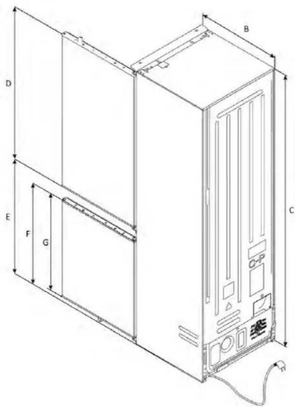
cable length 2270mm
| ; w w JD | ; w w J | ; w w J | ; w w J | ; w w J & | ; w w J | ; w w J | ||
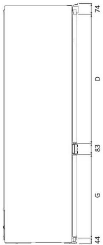
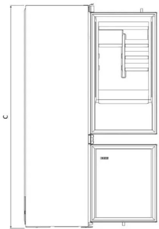
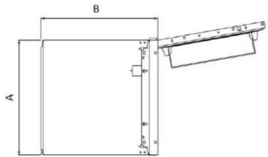
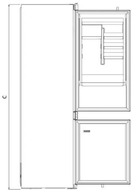
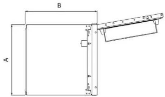
| 540±21 | 550±2 | 1772±2 | 970 | 745 | 662 | 618 | ||
| 540±22 | 550±2 | 1935±2 | 1133 | 745 | 662 | 618 | ||
| 690±23 | 550±2 | 1935±2 | 1133 | 745 | 662 | 618 |
Dimensions in mm
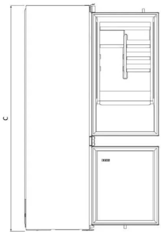
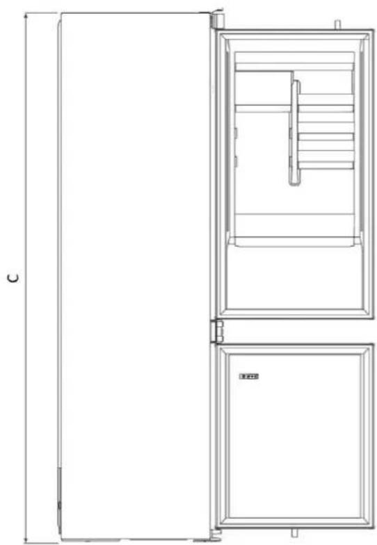
Side view with doors closed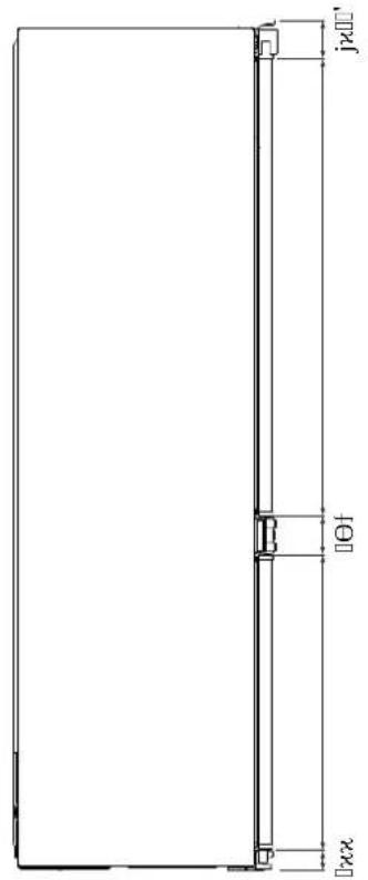
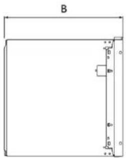
Top view
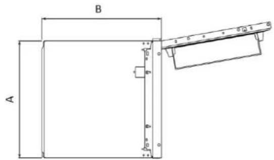
with doors closed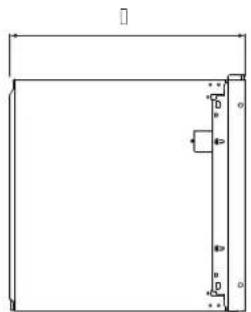
Side view with doors open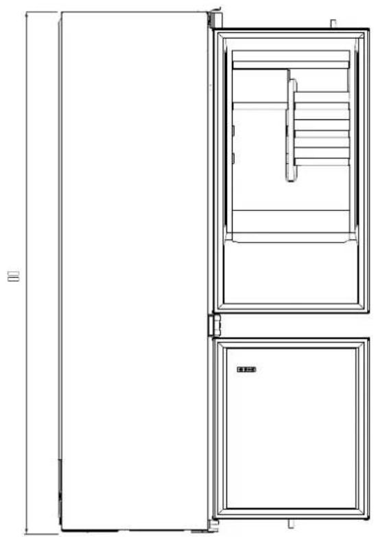
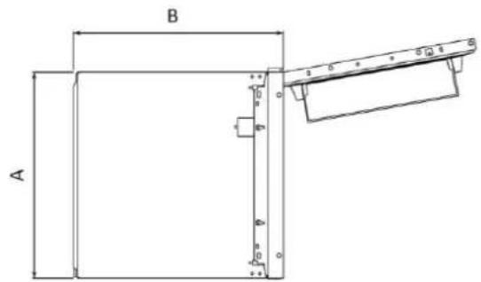
Top view
with doors open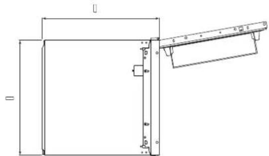
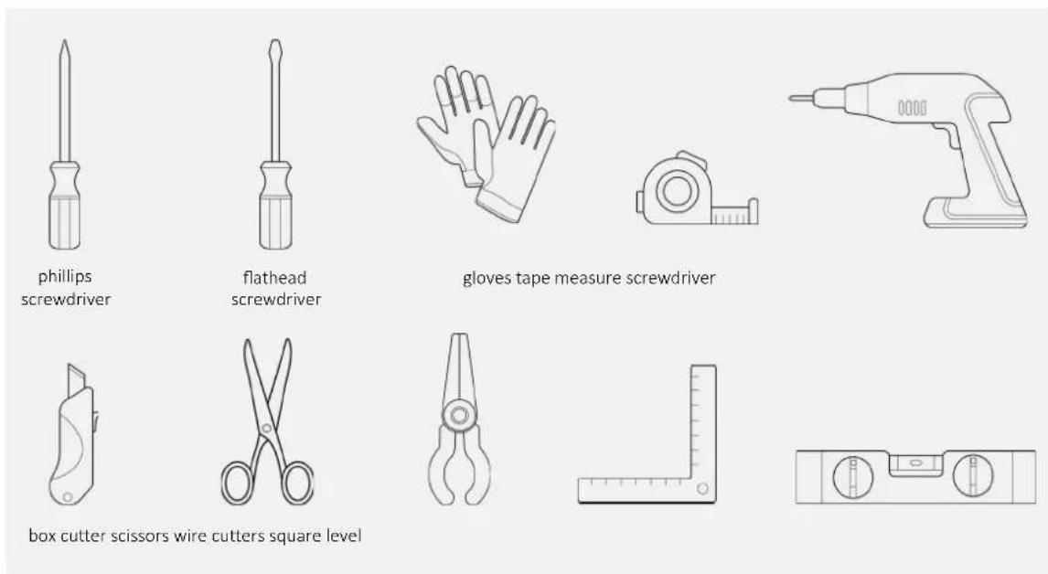
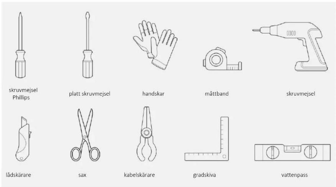
4 Installation tools
Tools needed
Accessories provided
5 Cabinet dimensions
Precautions 5.1
- Provide the built-in compartment without a back wall;
- For product ventilation, follow the instructions in this manual;
- It is recommended to secure the unit to the wall to prevent tipping.
Dimensions in mm 5.2
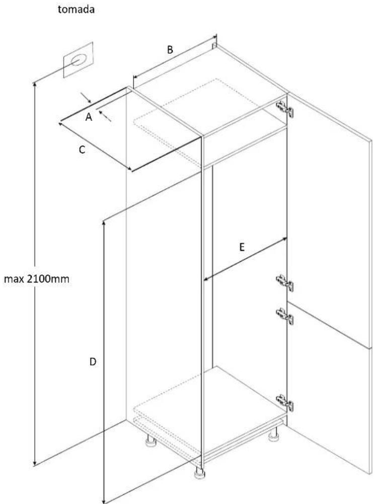
Front axonometric view
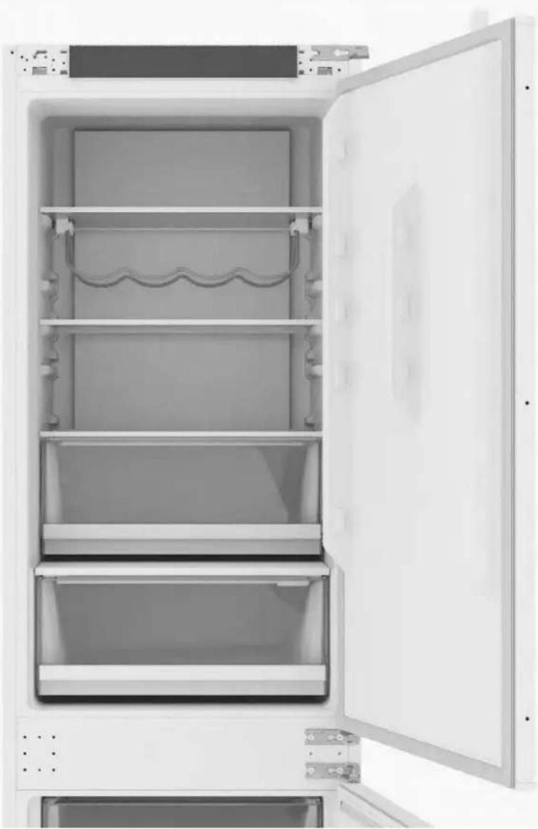
with doors open

| ☐;ŵwJD | ŽĚGUE ☐;ŵwJ ☐;ŵwJ | ☐;ŵwJ | ☐;ŵwJ ZG | WÄdÜ | ||
| 1 | Min. | 50 | 400 | 560 | 1778 | 560 |
| Recommended | 580 | 1780 | 562 | |||
| Max. | - | 1782 | 568 | |||
| 2 | Min. | 50 | 400 | 560 | 1941 | 560 |
| Recommended | 580 | 1943 | 562 | |||
| Max. | - | 1945 | 568 | |||
| 3 | Min. | 50 | 400 | 560 | 1941 | 710 |
| Recommended | 580 | 1943 | 712 | |||
| Max. | - | 1945 | 718 | |||
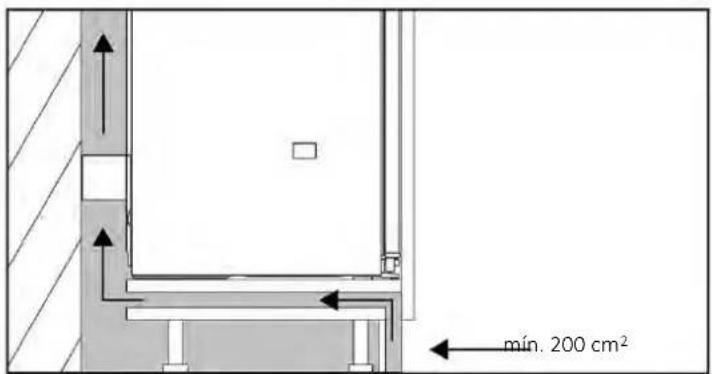
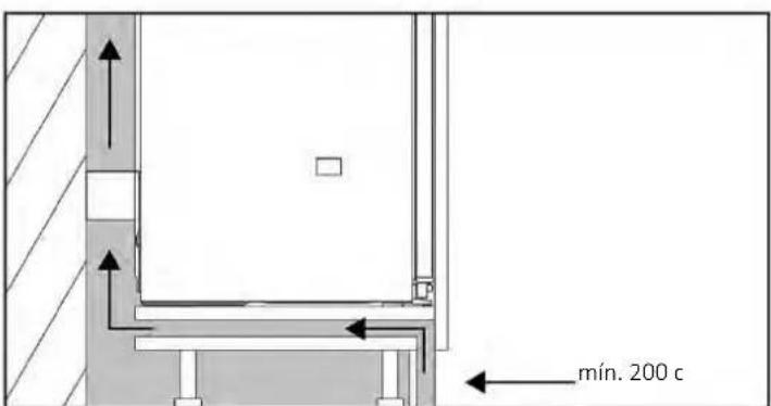
Installation in column 6.1
Side section Side section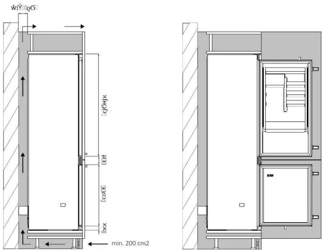
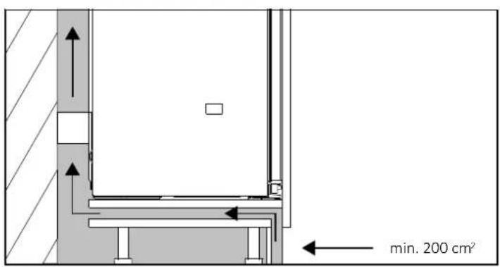
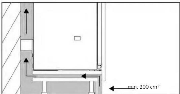
If it is not possible to create an opening in the baseboard, find an alternative solution to ensure proper air circulation.
You can view the product installation video by scanning the QR code.

or by clicking
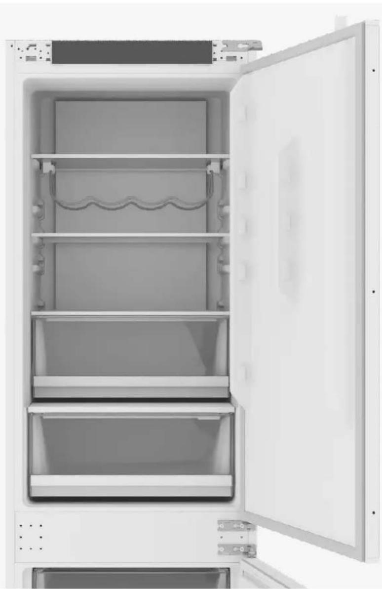
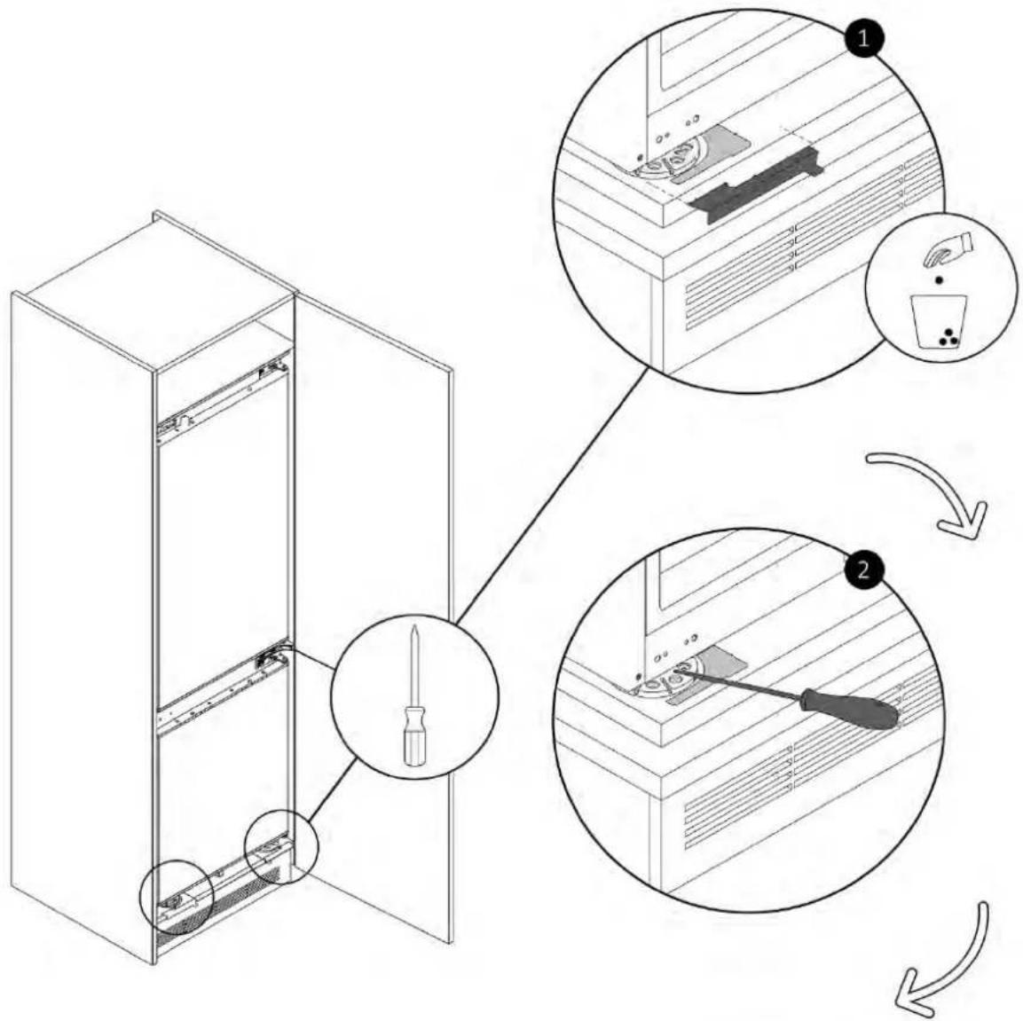
8.1 Unlocking the doors
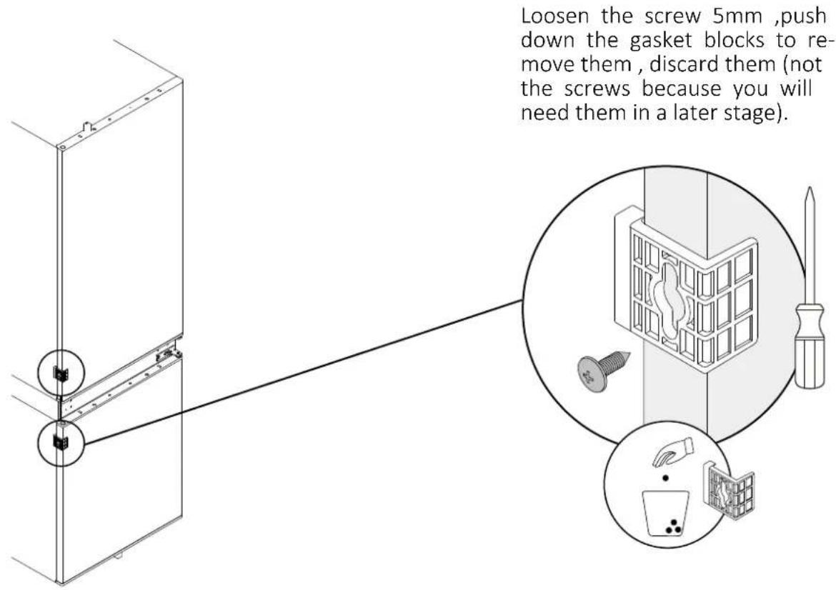
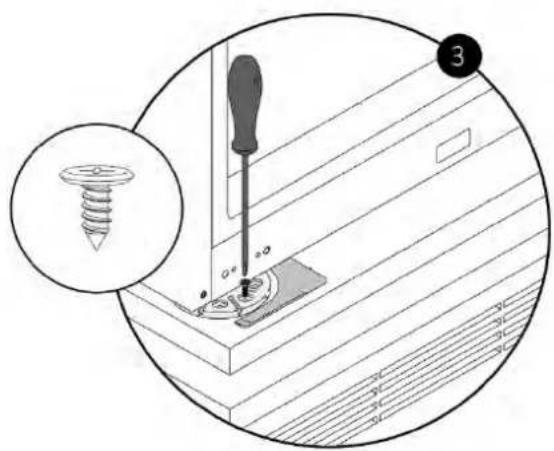
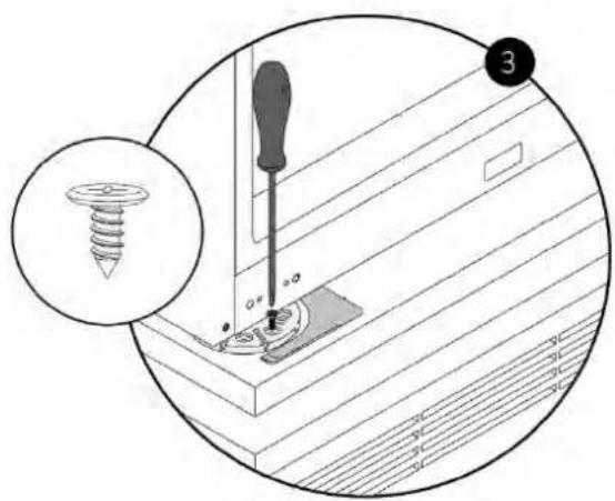
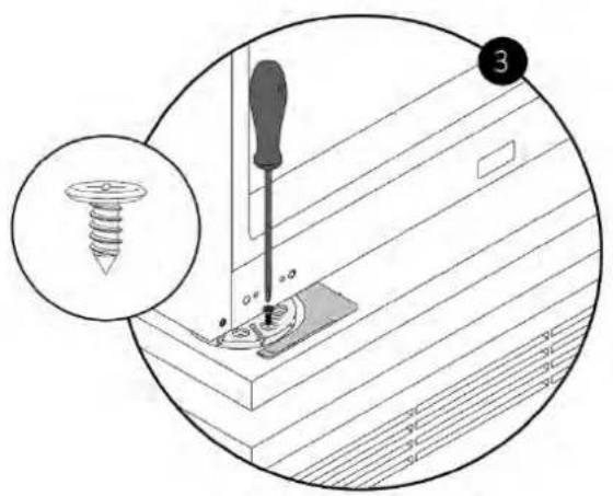
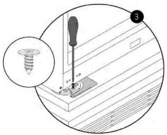
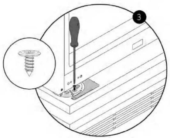
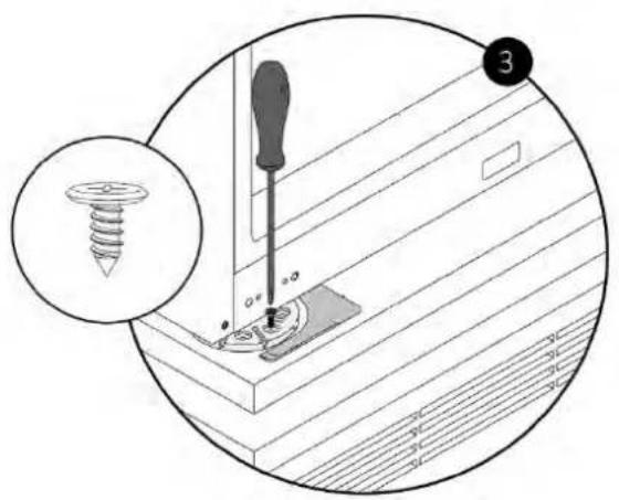
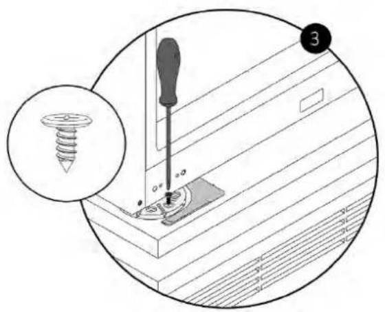
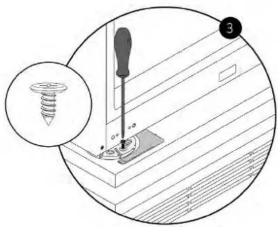
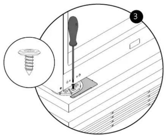
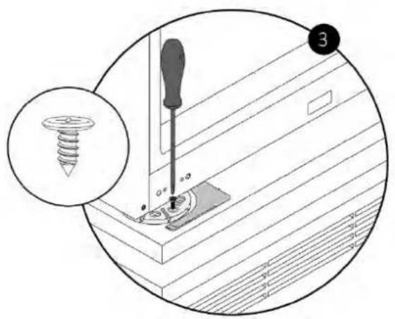
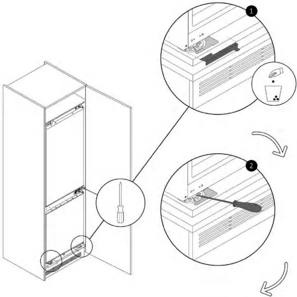
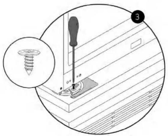
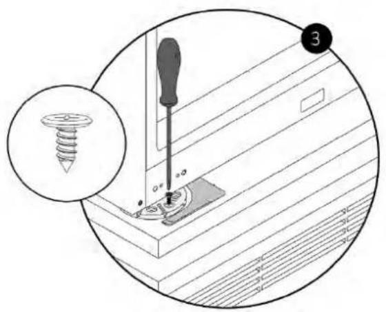
8.2 Removing the bottom screw
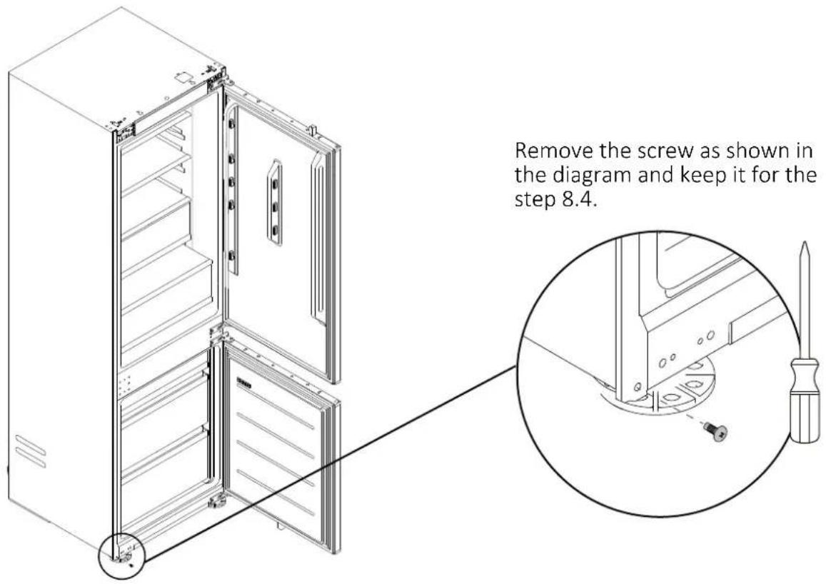
NOTE: Follow the following instructions only if it is necessary to reverse the direction of door opening; otherwise, proceed to the next paragraph (page 16).
Hinges inversion 8.3
Rotate the hinges 180° and mount them as shown in the diagram.
![graph TD subgraph Server_Rack1 A1["Server Rack A"] --> B1["Component A"] B1 --> C1["Component C"] C1 --> D1["Component D"] D1 --> A2["Component A"] A2 --> B2["Component B"] B2 --> C2["Component C"] C2 --> D2["Component D"] D2 --> A3["Component A"] A3 --> B3["Component B"] B3 --> C3["Component C"] C3…](/content/2026/04/732472/images/0832fa6e4ecbf51afe0a6cfe3ecfff5618dea674a2dd1b11fc5641ce79756e77.jpg)
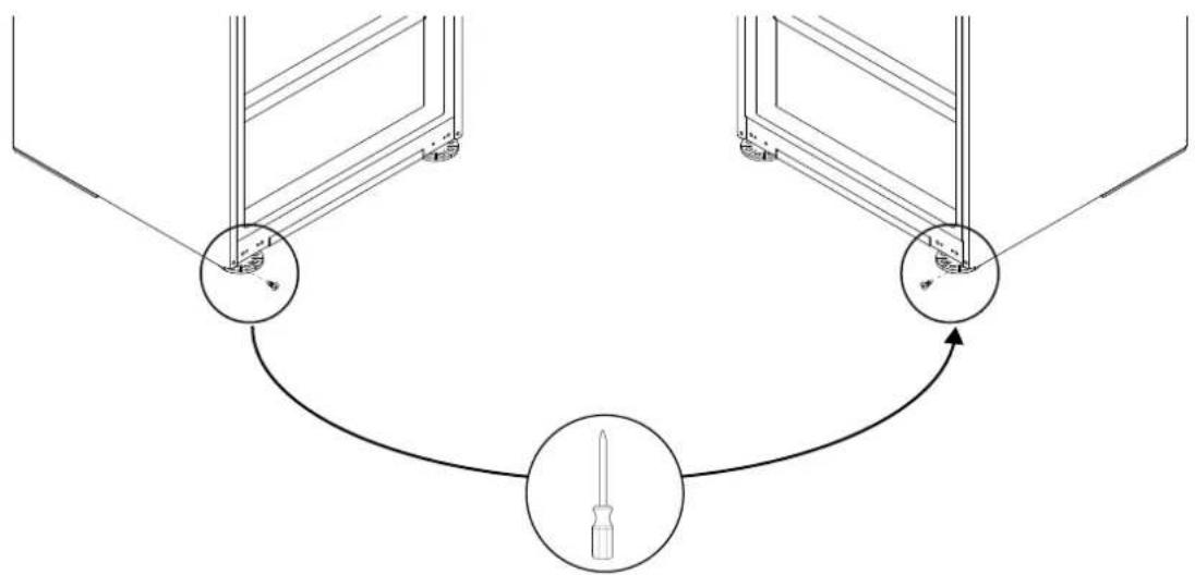
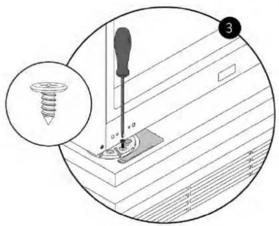
8.4 Attaching the bottom screw on the opposite side of the refrigerator
Tighten the screw (from step 8.2) on the opposite side of the refrigerator as shown in the diagram.
9 Installation instructions for the refrigerator
Before proceeding, if you have not completed step 8.1 yet, do it now.
Applying the top installation bar of the refrigerator (9.1)
Applying the adhesive spacers on the side of the refrigerator (9.2)
9.3 Centering the refrigerator feet
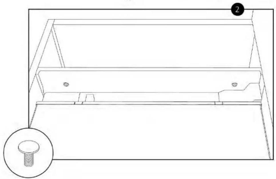
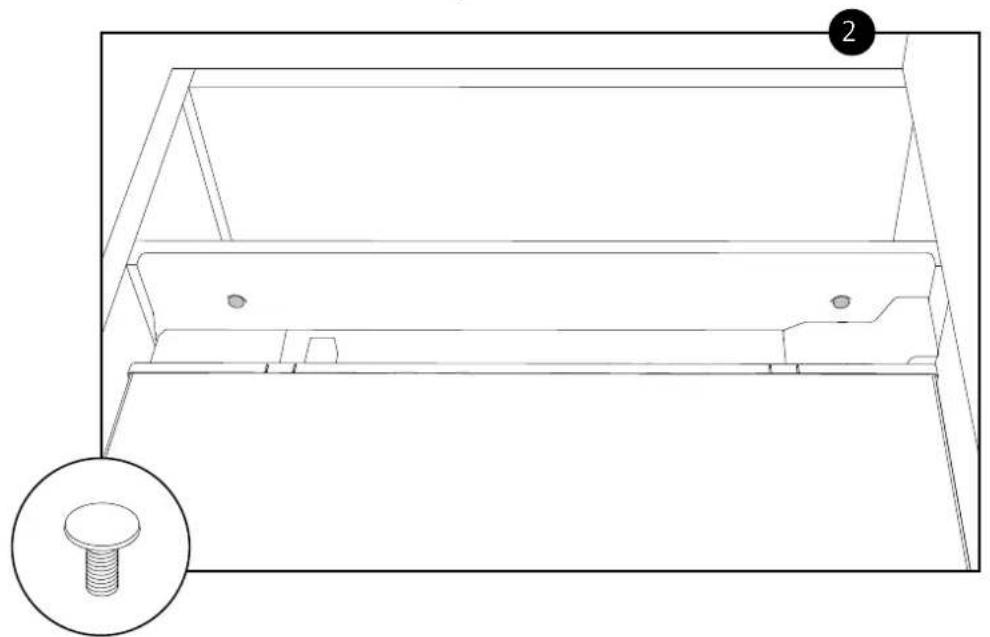
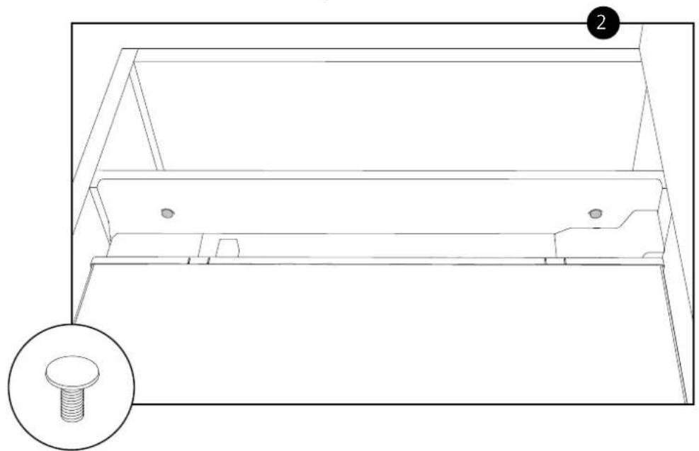
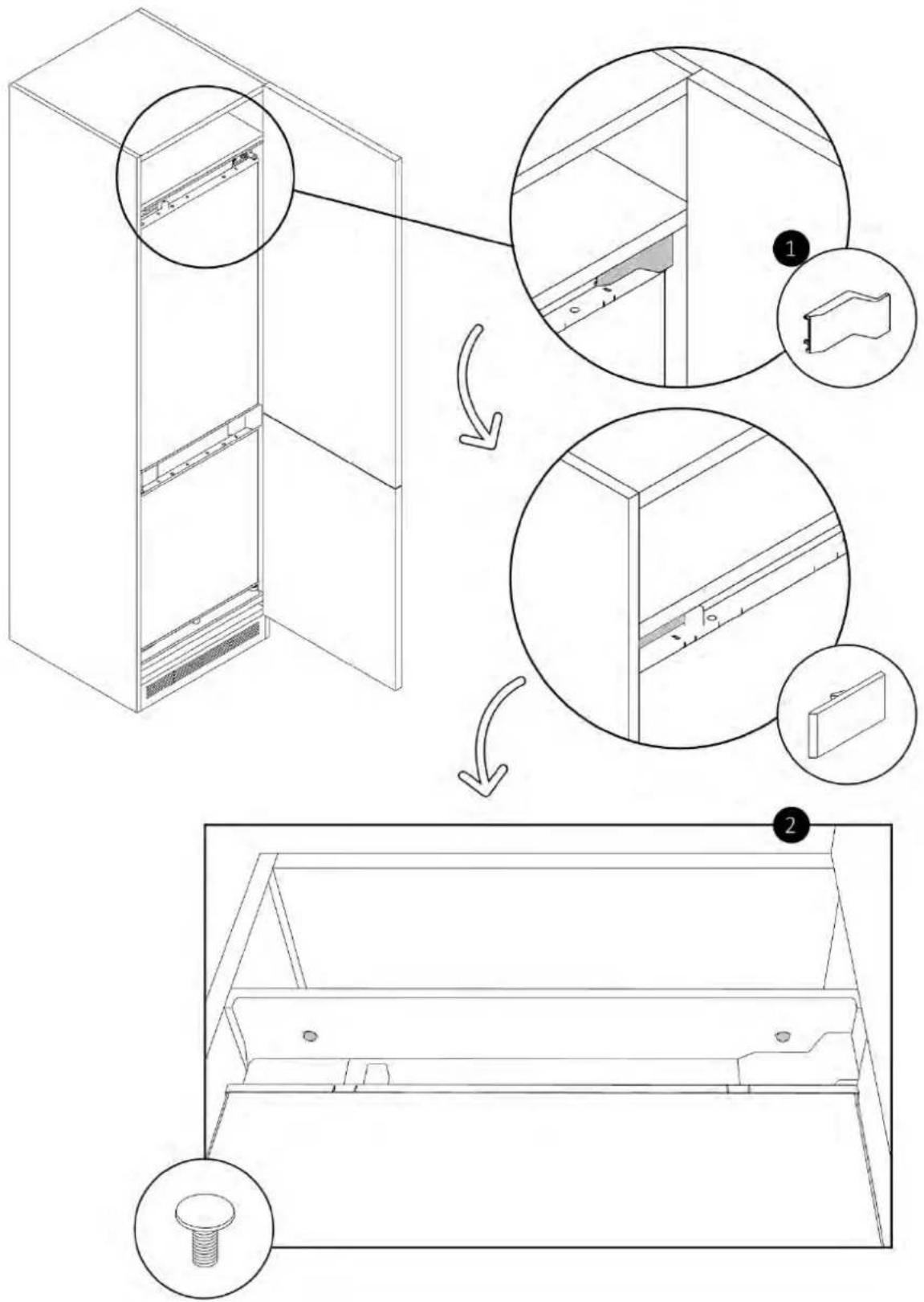
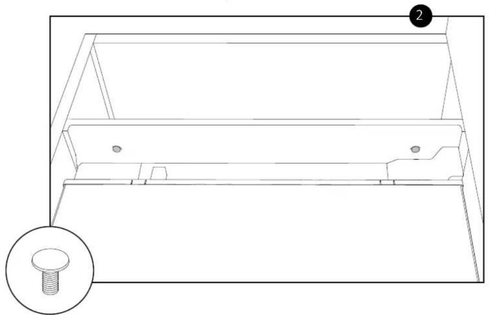
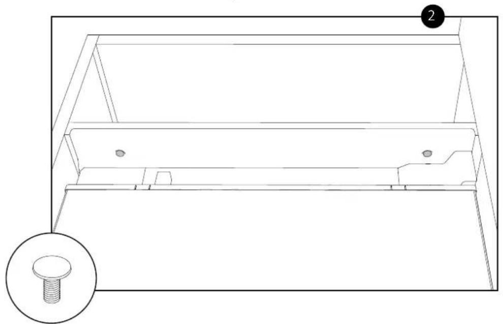
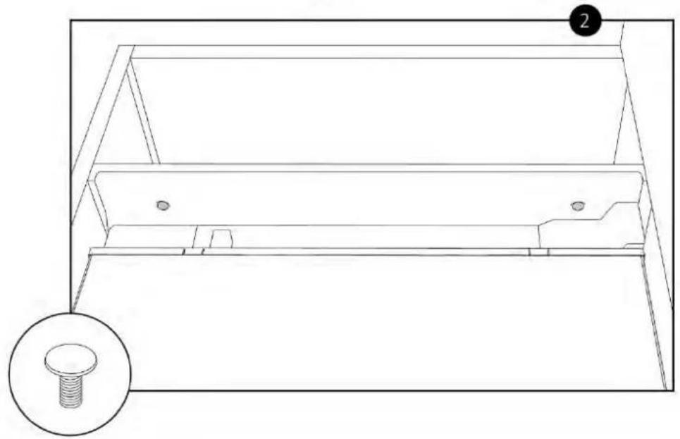
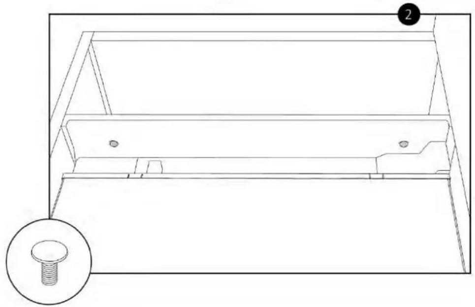
Install the centering gauges for the feet on the bottom of the cabinet using the provided screws. Remove any excess parts as shown in the diagram.
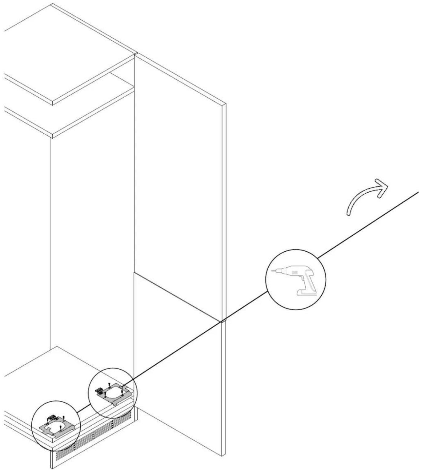
9.3 Centering the refrigerator feet
![graph TD A["Step 1: Assembly of a microchip"] --> B["Step 2: Insert a component into a device"] B --> C["Step 3: Setup a microchip on a wall"] style A fill:#f9f,stroke:#333 style B fill:#ccf,stroke:#333 style C fill:#cfc,stroke:#333](/content/2026/04/732472/images/b6d7cdeaf32e457ec658af631a68fc622b917ba35b7bdc60be169044f22496a7.jpg)
9 Installation instructions for the refrigerator
WARNING: before inserting the refrigerator into the cabinet, thread the power cord through and temporarily secure it on top with tape. Then, lift the product with two people and insert it into the recess, taking care not to damage the power cord. Ensure that the outlet must be freely accessible.
Built-in installation (9.4)
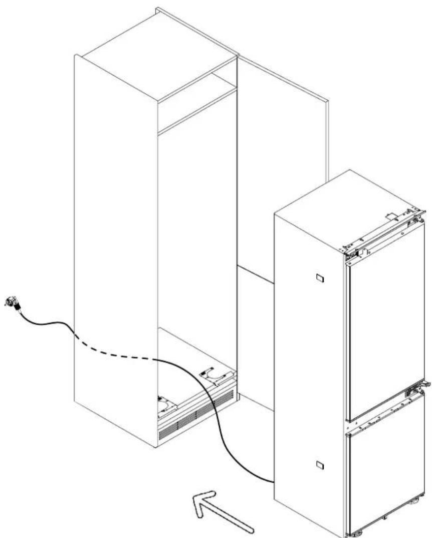
Built-in installation (9.4)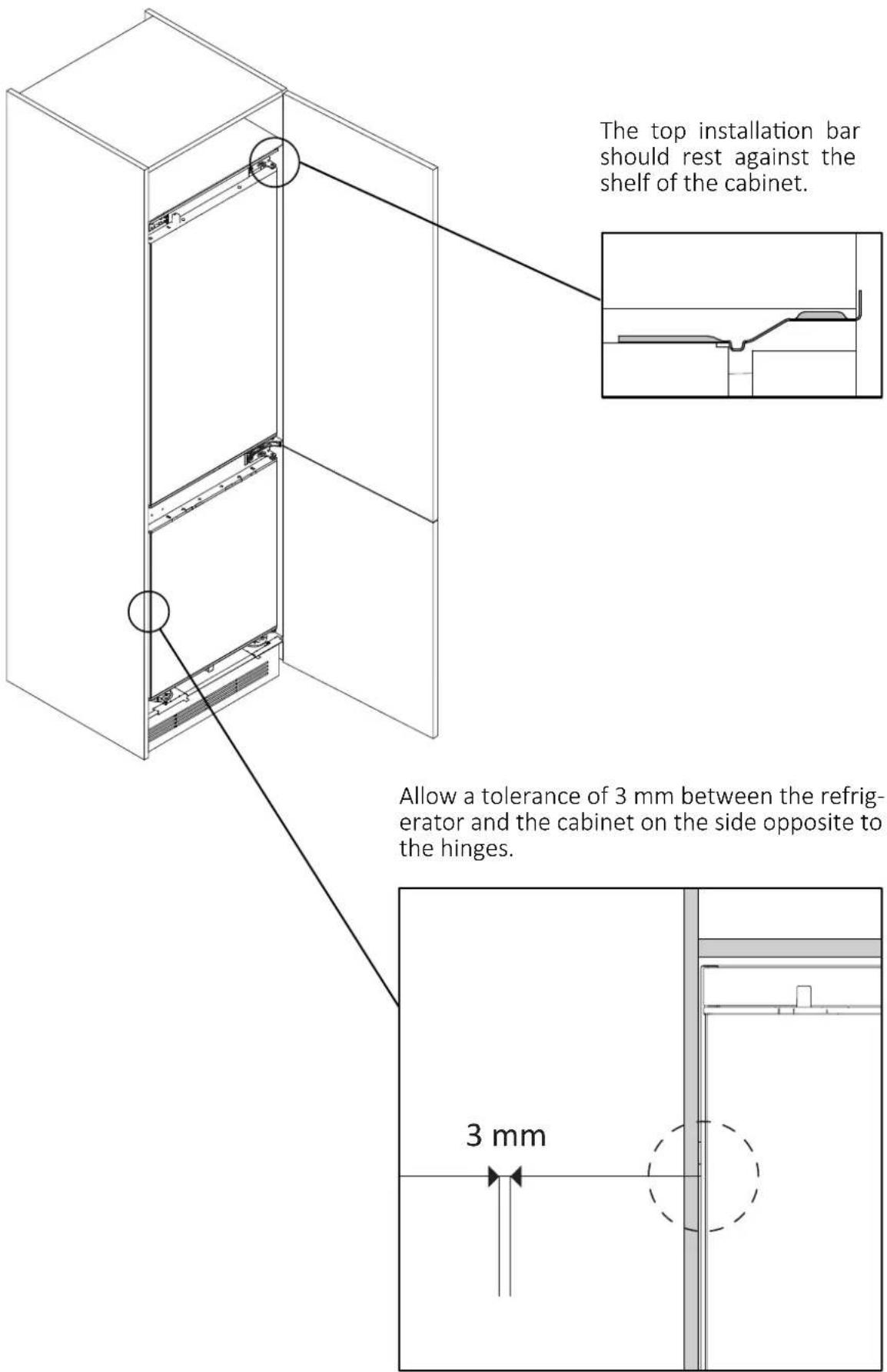
9 Installation instructions for the refrigerator
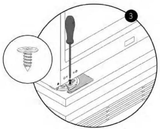
9.5 Securing the refrigerator feet
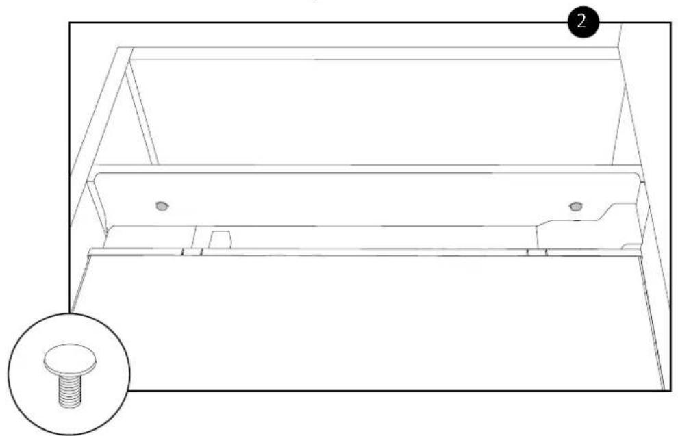
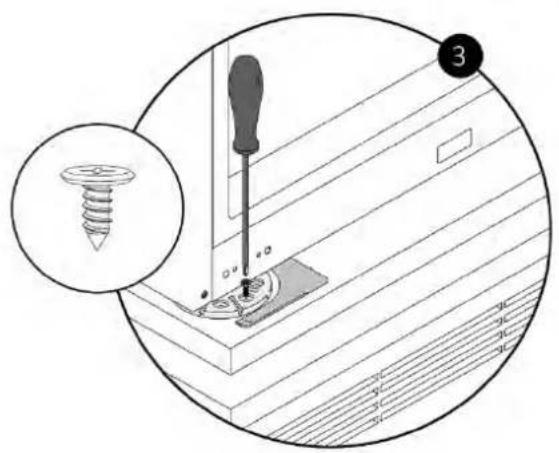
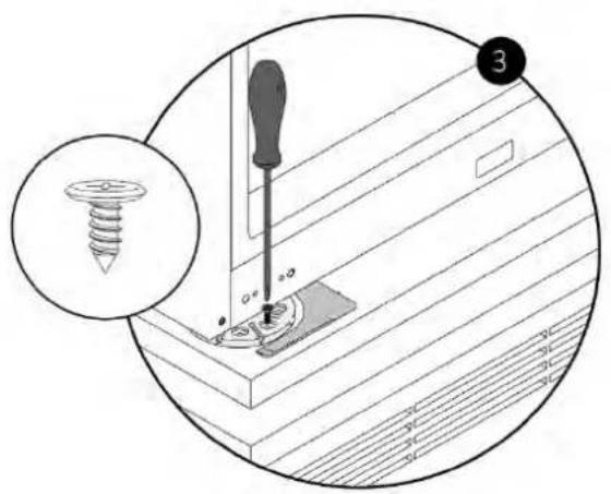
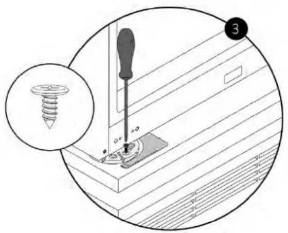
Remove the fin from the foot centering component. Adjust to the desired height and secure the refrigerator feet to the cabinet using the provided screws.
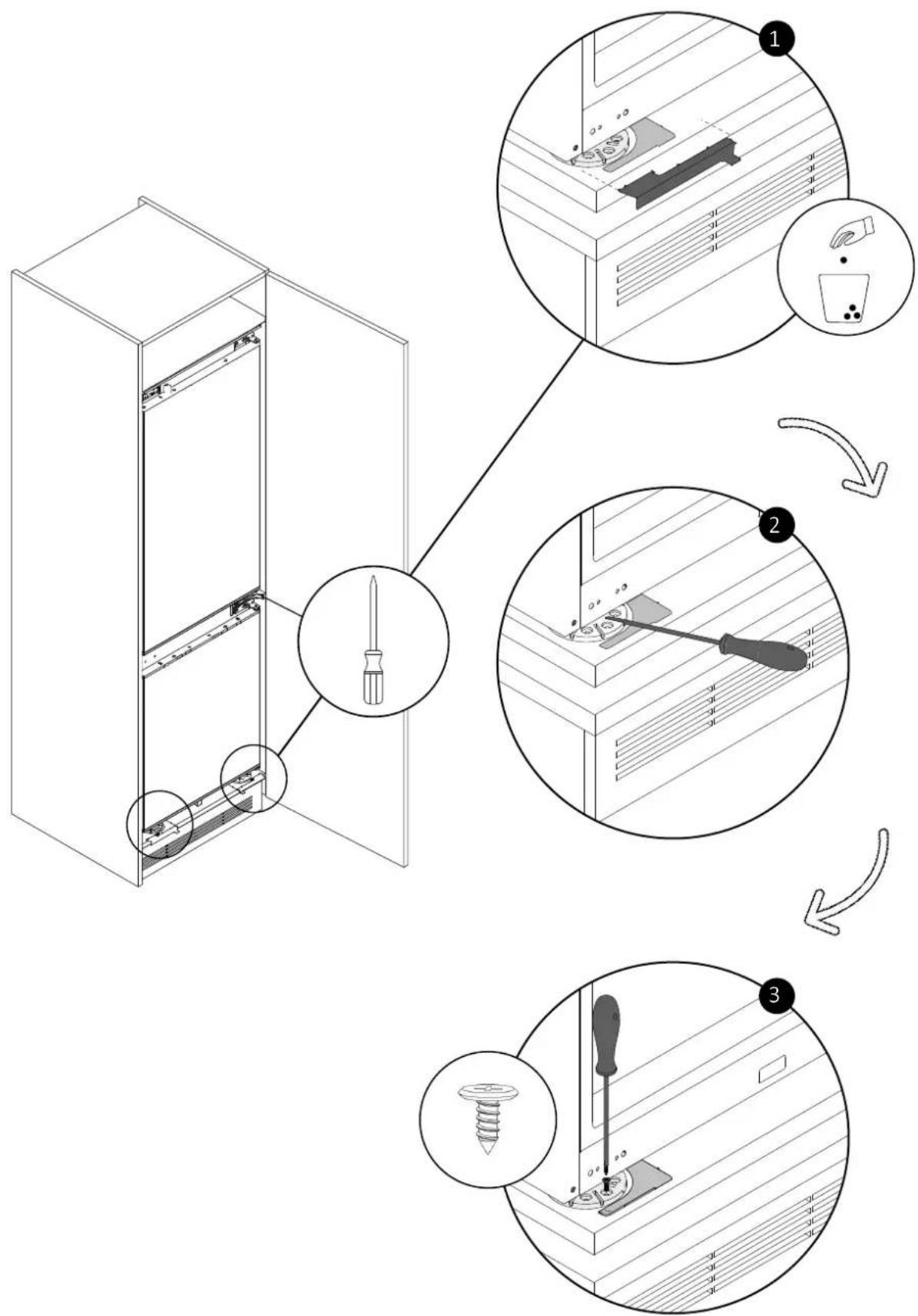
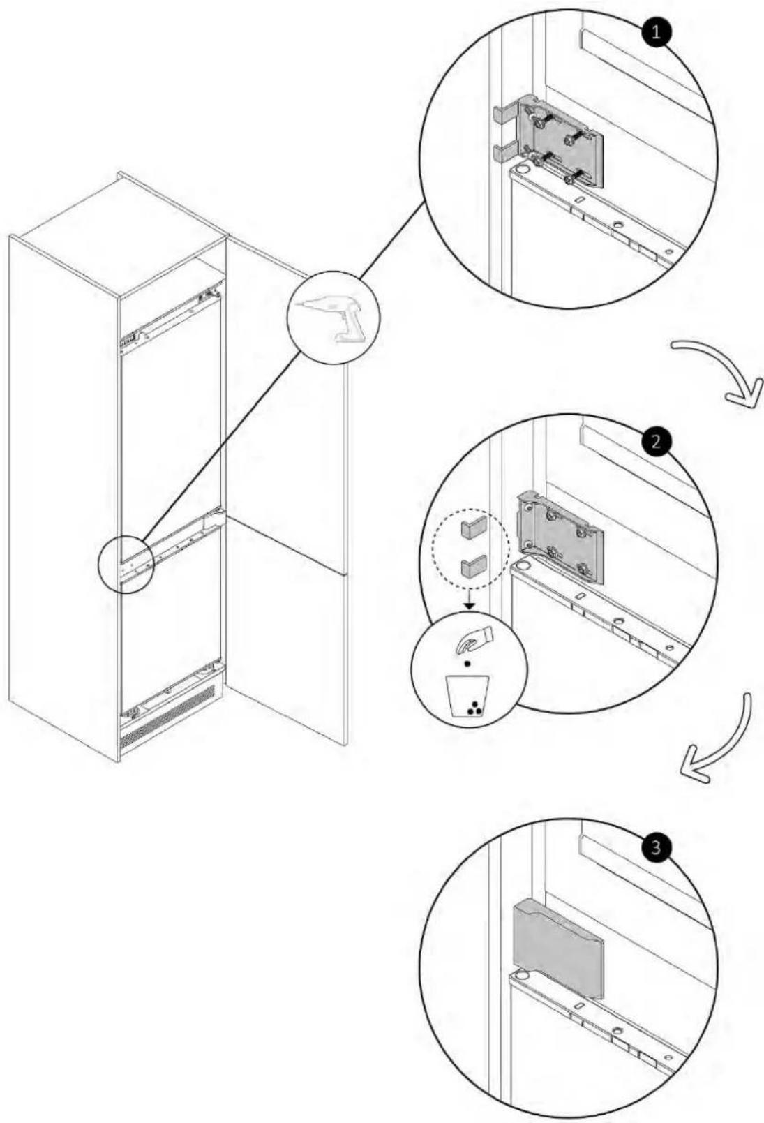
9.6 Mounting the central brackets and covers
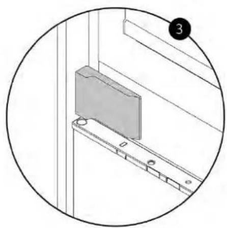
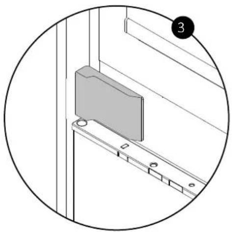
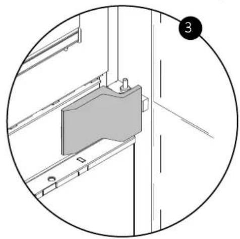
Using the provided screws, attach the bracket on the refrigerator's opening side. Remove the positioning fin. Finally, place the cover.

9 Installation instructions for the refrigerator
9.6 Mounting the central brackets and covers
Using the provided screws, attach the bracket on the side opposite to the hinges. Remove the positioning fins. Finally, place the cover.
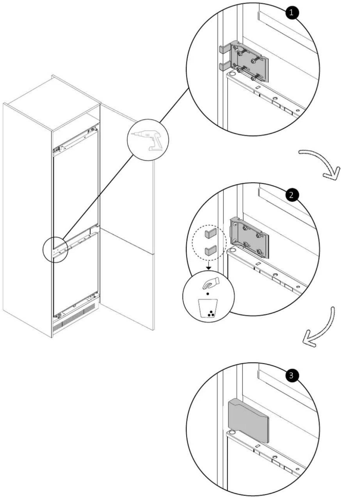
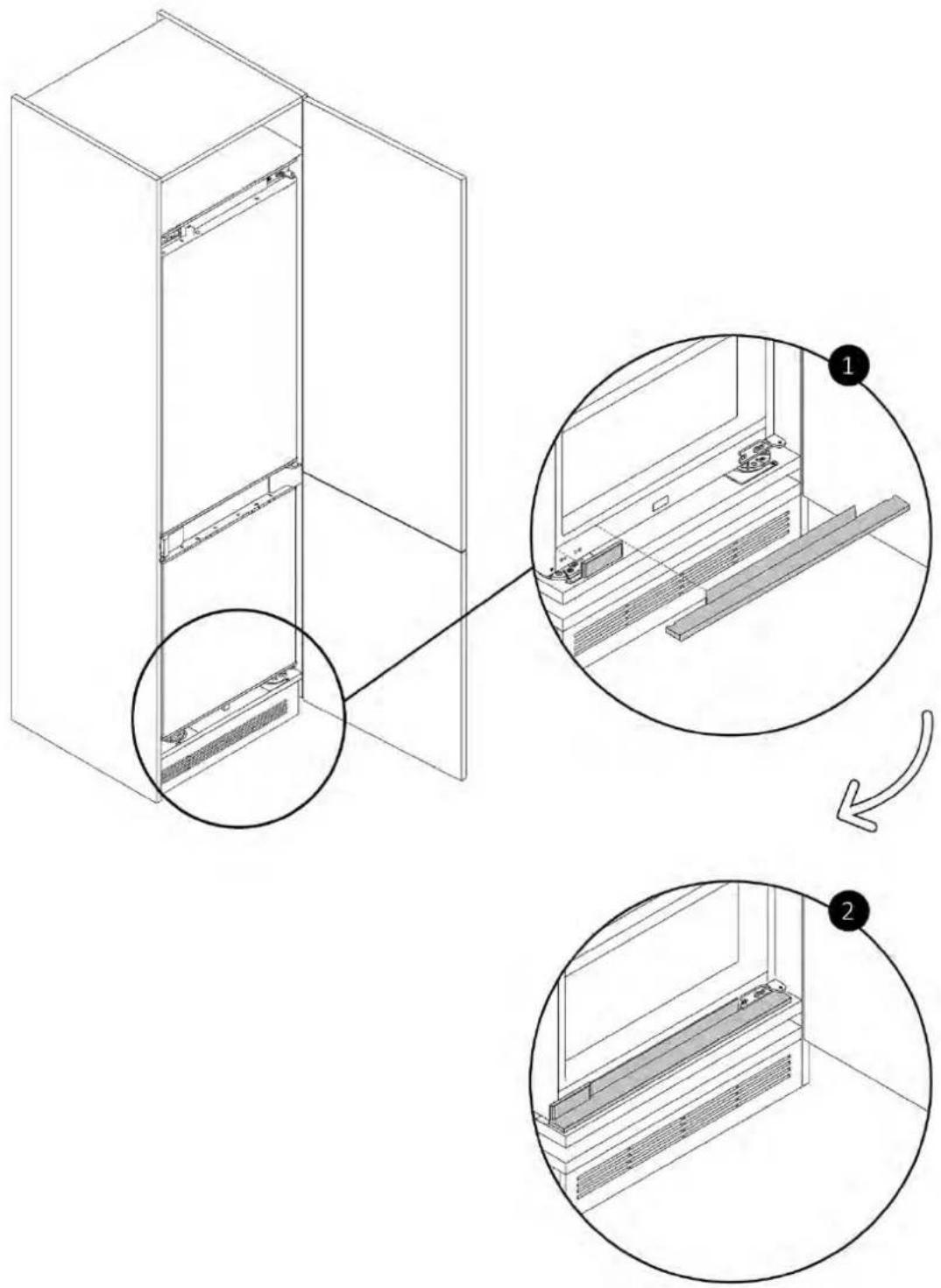
9.7 Mounting the bottom covers
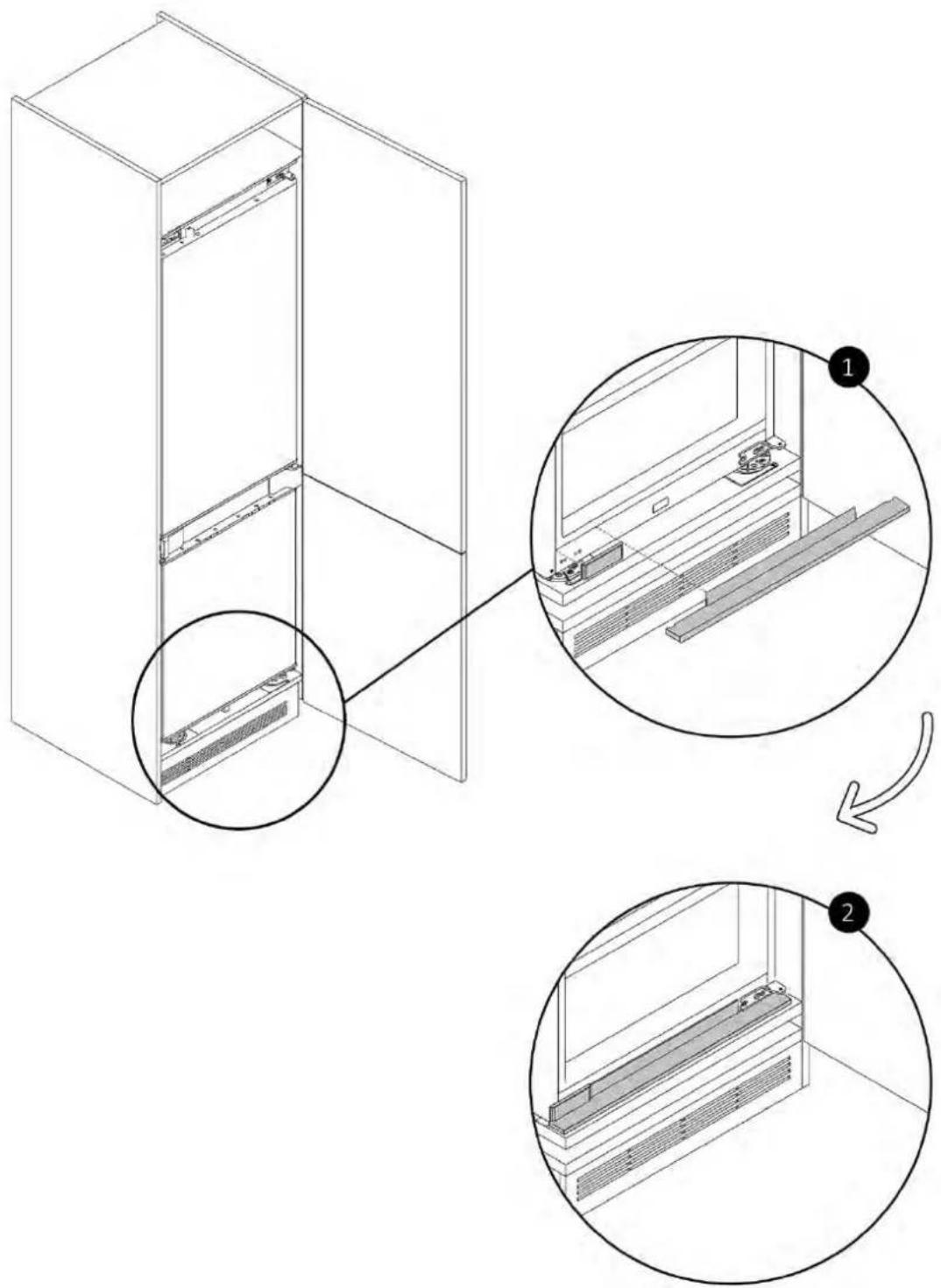
Apply the two bottom covers, securing them as shown in the diagram.
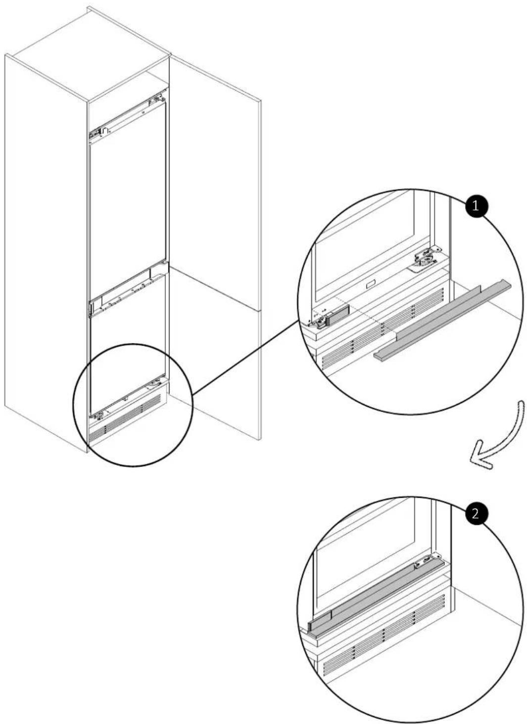
9 Installation instructions for the refrigerator
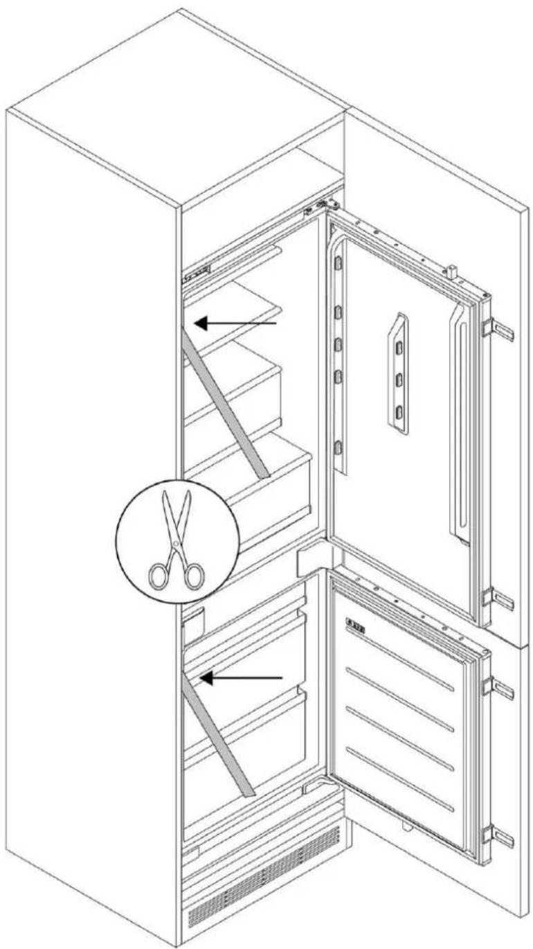
9.8 Applying gaskets on the side of the refrigerator
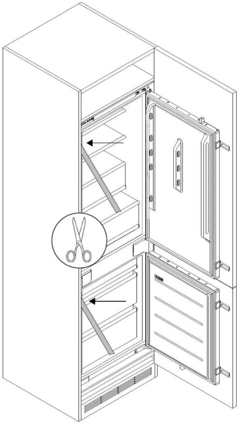
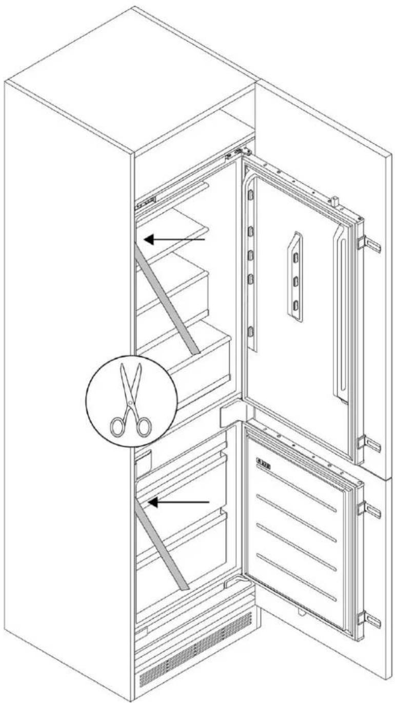
Cut the gaskets to size and apply them to the side of the refrigerator, on the side opposite to the hinges.
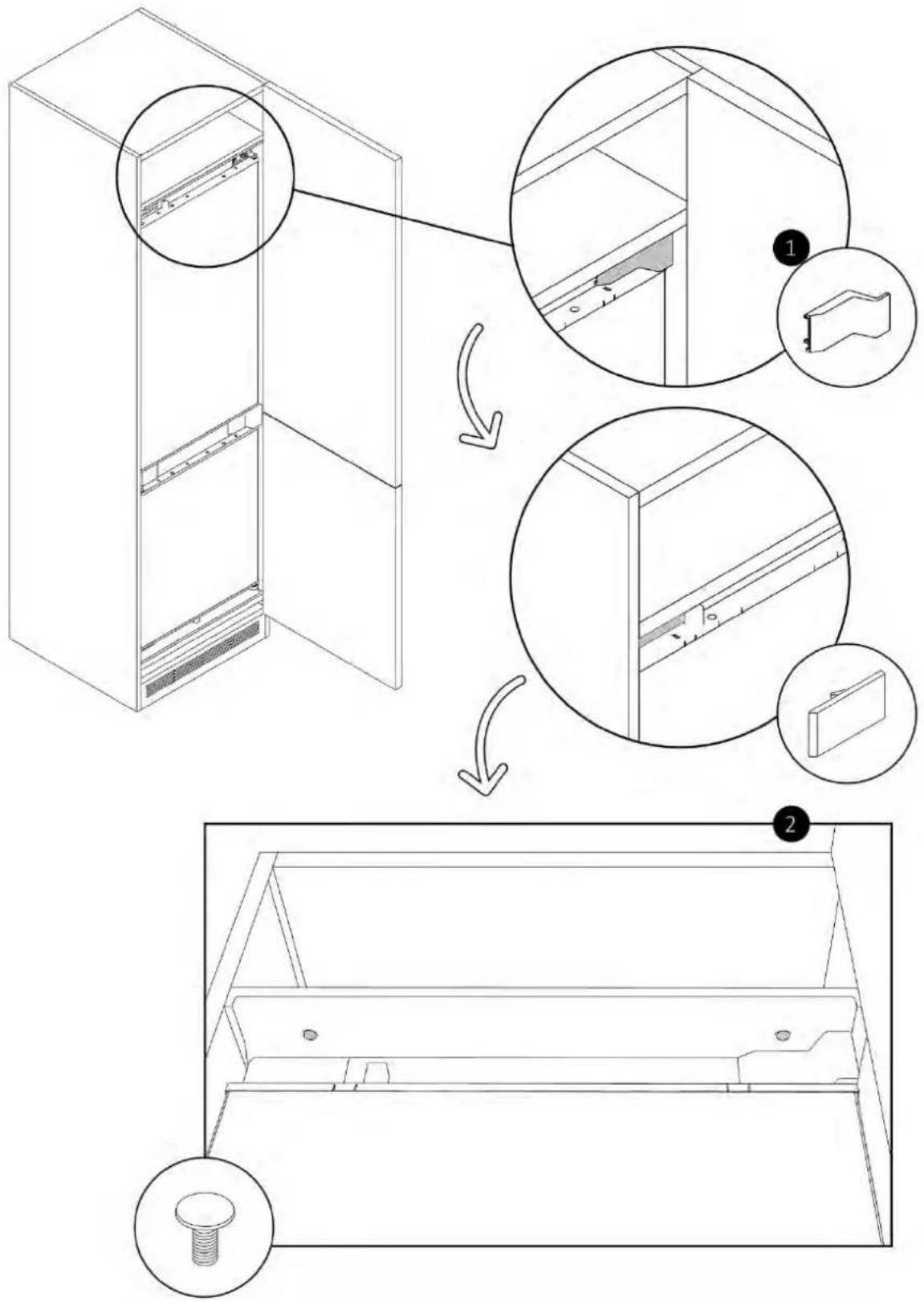
9.9 Mounting the top covers and securing the refrigerator to the upper shelf
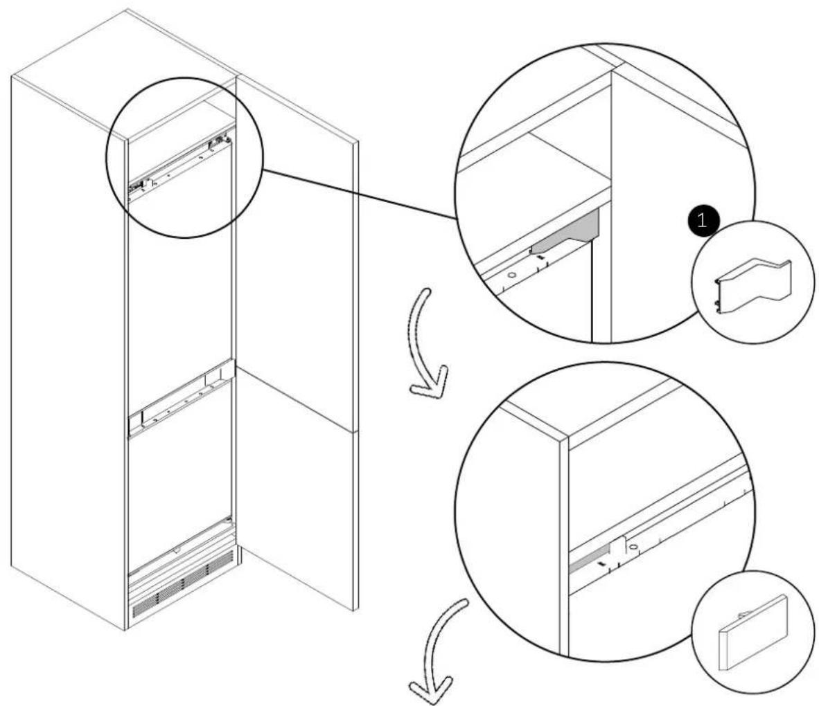
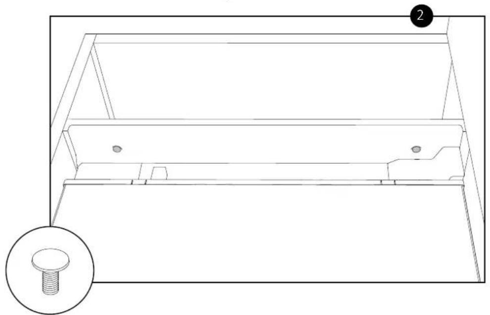
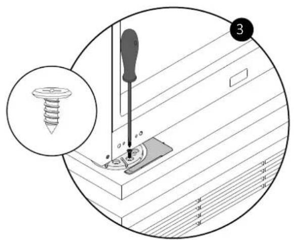
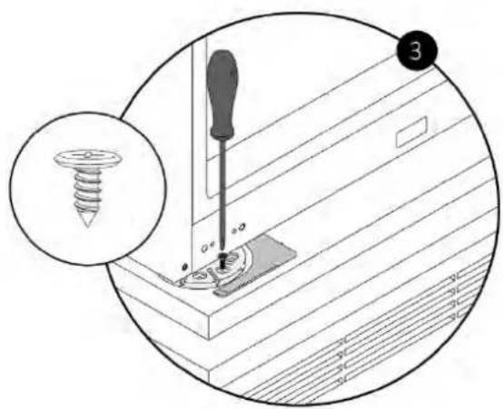
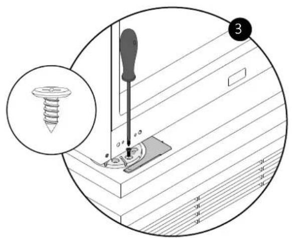
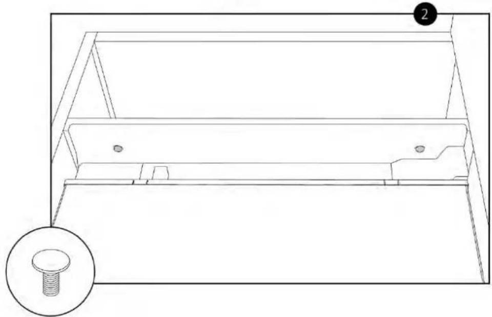
Using the provided screws, secure the upper front panel to the cabinet shelf, then cover the upper hinge and the opposite side with the covers.
9 Installation instructions for the refrigerator
Attaching the sliding hinges to the cabinet door9.10
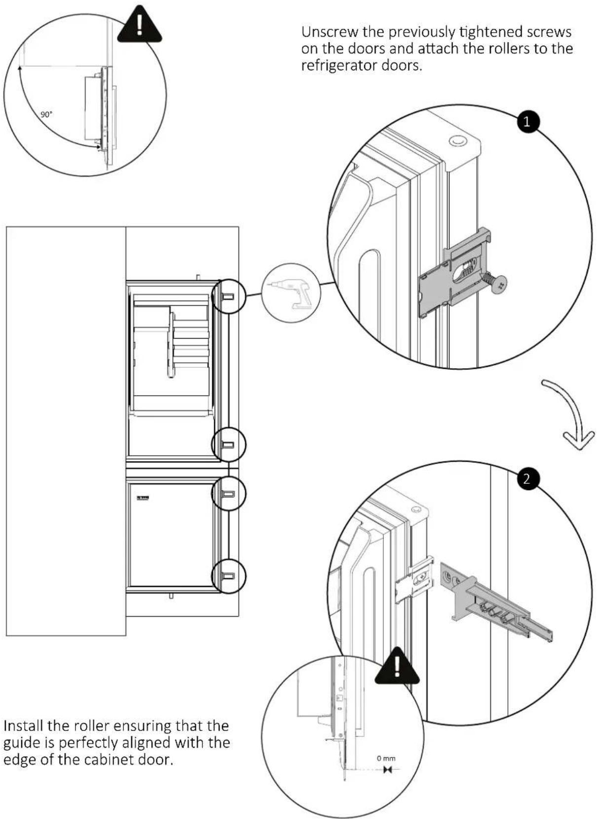
Before starting, ensure that both the cabinet door and the refrigerator door are perfectly open at 90 degrees.
Attaching the sliding hinges to the cabinet door9.10
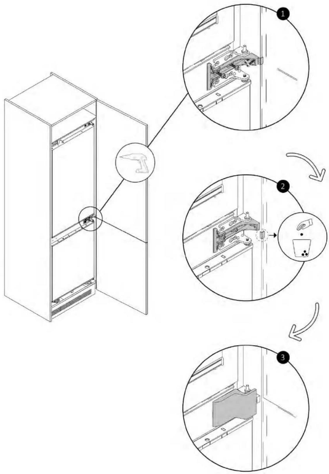
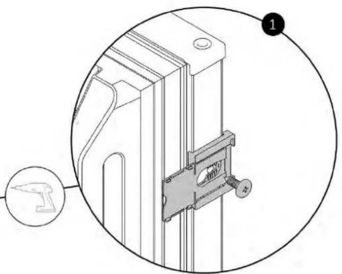
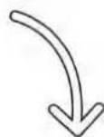
Using a screwdriver, secure the rollers to the cabinet doors. Then, remove the guides as shown in the diagram.
![graph TD A["Step 3: Initial structural assembly"] --> B["Step 4: Assembly with hand tool"] B --> C["Step 4: Final assembly with weights and dropouts"]](/content/2026/04/732472/images/ef7db6aab5d4d742ceeeb4c8523059d6f551163dbf546b20b082bf322b66d5ba.jpg)
Warnings 10.1
To safely perform the electrical connection of the appliance, observe the following warnings:
- Any repair, installation, and maintenance not performed correctly can seriously endanger the user;
- The manufacturing company declares no responsibility for direct or indirect damages caused by incorrect installation, maintenance, or repair interventions. The company also does not respond to damages caused by the lack or interruption of the grounding system (e.g., electric shock);
- Connect the product exclusively using the provided power cord;
- The product must be connected to an electrical system installed professionally; • In case of damage caused by improper connection, the warranty is void;
- For any repairs, contact Customer Service exclusively and request the use of original spare parts;
- Disconnect the product from the electrical supply before performing any intervention or maintenance on it. • To avoid the risk of fire or electrical shock, do not damage the plug or power cord;
- Do not connect the appliance to power strips, extension cords, or portable power supplies;
- When the appliance is placed in the chosen location, make sure the power cord is not stuck or damaged and that there are no power strips or portable power supplies in the back of the appliance.
Power absorbed
See product data plate.
Differential circuit breaker (life-saving)
The use of a residual current circuit breaker (earth leakage circuit breaker) with trip current complying with current standards is recommended.
⚠ WARNING: the product must be connected to the power supply via an omnipolar disconnection device that ensures a separation between contacts complying with overvoltage category III. Such a device must withstand the maximum loads connected and comply with current standards.
- Make sure the electrical specifications on the data plate are in conformity with the power supply; • The appliance operates on 220-240 Vac/50 Hz electric current;
- Abnormal voltage fluctuations may cause the appliance not to start, damage to the temperature control or compressor, or abnormal noises during operation. In such a case, an automatic regulator should be fitted;
- Ensure that the main cable is not caught under the appliance during and after transportation/movement, to prevent the main cable from being cut or damaged. If the power cord of the appliance should be damaged, do not proceed with the installation and contact service;
- Ensure that the power source, plug, and fuses are conform to the data on the data plate;
- Make sure the power plug is grounded and do not use power strips or extension cords.
NOTE (United Kingdom only): the power cord of the appliance is equipped with a 3-prong plug (grounded) suitable for a standard 3-prong outlet (grounded).
Never cut or remove the third prong (ground connection). After installing the appliance, the plug must remain accessible.
Other advices10.2
The use of any household appliance requires adherence to certain basic rules:
- It is recommended to keep the plug clean: any dirt residue on the plug may cause fire;
- Do not pull the power cord to disconnect the appliance from the power supply while operating;
- Do not touch the appliance with wet or damp hands or feet. The use of adapters, power strips or extension cords is discouraged;
- In case of malfunction and/or performance drop, turn off the appliance and do not manipulate/altere it.
11 Deliver to the user
At the end of installation:
• Inform the user about essential functions; • Inform the user about all aspects relevant to safe use and handling; • Deliver accessories and instructions for use and assembly to the user to be kept with care.
After installation is complete, remove the protective film, tape, and all other packing materials.
After turning the fridge on, wait at least 2 hours before placing food in the appliance to ensure the correct temperature inside the fridge.

WARNING: the product requires adequate ventilation for normal operation. Do not obstruct the ventilation openings for any reason.

NOTE: the actual appearance of the product depends on the model chosen.
12 Disassemble the product
- Disconnect the product from the power supply; • Unscrew the fixing screws;
- Lift the product slightly and pull it out completely;
- This product will not damage the cabinet, which can also be used with a new appliance.

WELCOME
Top view
with doors open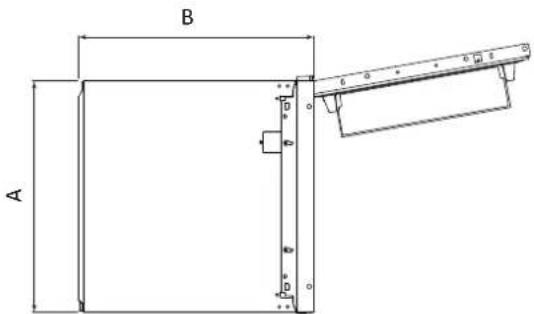
9.4 Recess
WELCOME
Cable length 2270mm
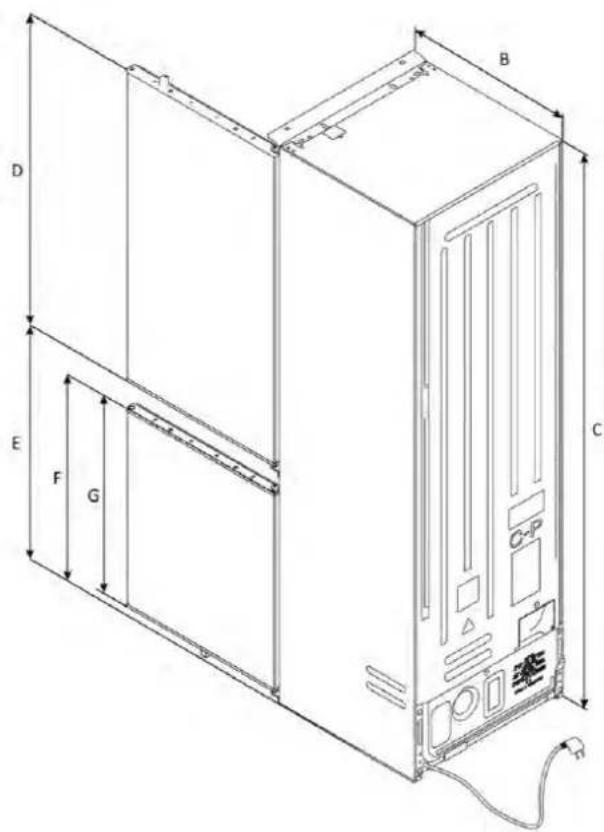
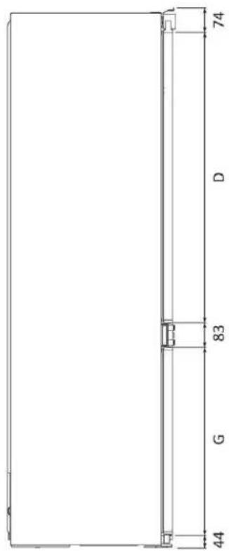
| Modelle | A (mm) | B (mm) | C (mm) | D (mm) | E (mm) | F (mm) | G (mm) |
| 1 | 540 ±2 | 550 ±2 | 1772 ±2 | 970 | 745 | 662 | 618 |
| 2 | 540 ±2 | 550 ±2 | 1935 ±2 | 1133 | 745 | 662 | 618 |
| 3 | 690 ±2 | 550±2 | 1935 ±2 | 1133 | 745 | 662 | 618 |
Dimensions in mm
Side view
Side view
Top view
10.1 Warnings
WELCOME
Side view
with doors open
Top view
with doors open
WELCOME
Side view
Top view
or by clicking
this link
10.1 Warnings
WELCOME
Side view
Top view
or by clicking
on this link
9.4 Recessed installation
WELCOME
Side view
Top view
or by clicking
this link
10.1 Warnings
WELCOME
Rear axonometric view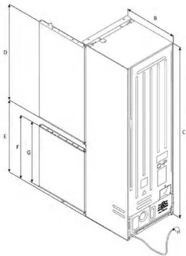
Side view
with doors open
Top view
with doors open
with doors open
| Modelos | A (mm) | B (mm) | C (mm) | D (mm) | E (mm) | Observação | |
| 1 | Mín. | 50 | 400 | 560 | 1778 | 560 | Dobradiças: 17 mm |
| Recomendado | 580 | 1780 | 562 | ||||
| Máx. | - | 1782 | 568 | ||||
| 2 | Mín. | 50 | 400 | 560 | 1941 | 560 | |
| Recomendado | 580 | 1943 | 562 | ||||
| Máx. | - | 1945 | 568 | ||||
| 3 | Mín. | 50 | 400 | 560 | 1941 | 710 | |
| Recomendado | 580 | 1943 | 712 | ||||
| Máx. | - | 1945 | 718 | ||||
or by clicking
this link
WELCOME
cable length 2270 mm
| A(mm) | Modellen | B(mm) | C(mm) | D(mm) | E(mm) | F(mm) | G(mm) | |
| 540±21 | 550±2 | 1772±2 | 970 | 745 | 662 | 618 | ||
| 540±22 | 550±2 | 1935±2 | 1133 | 745 | 662 | 618 | ||
| 690±23 | 550±2 | 1935±2 | 1133 | 745 | 662 | 618 |
Dimensions in mm
Top view
with doors open
9.6 Installation of the central brackets and covers
WELCOME
Top view
with doors open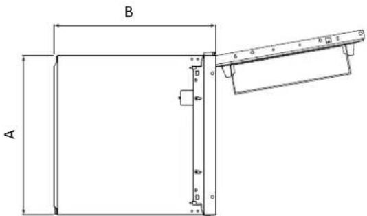
or as
click on
the following link
9.4 Collection
10.1 Warnings
WELCOME
Cable length 2270 mm
| Modeli | A (mm) | B (mm) | C (mm) | D (mm) | E (mm) | F (mm) | G (mm) |
| 1 | 540 ±2 | 550 ±2 | 1772 ±2 | 970 | 745 | 662 | 618 |
| 2 | 540 ±2 | 550 ±2 | 1935 ±2 | 1133 | 745 | 662 | 618 |
| 3 | 690 ±2 | 550±2 | 1935 ±2 | 1133 | 745 | 662 | 618 |
Dimensions in mm
Side view with doors open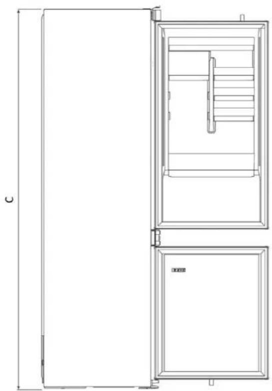
Top view
with doors open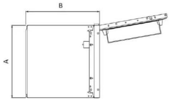
4 Installation tools
Required tools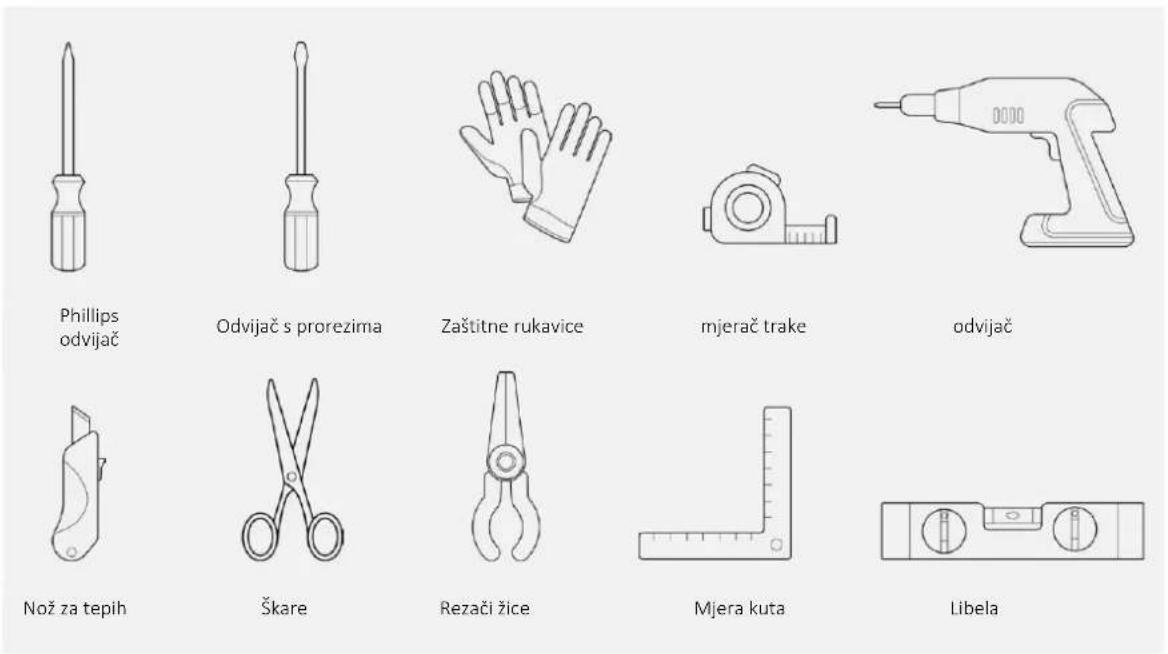
4 Installation tools
5.1 Safety precautions
or by clicking here
Left
9.3 Centering the refrigerator feet
![graph TD A["Step 1: Initial component"] --> B["Step 2: Tool placement"] B --> C["Step 3: Bracket assembly with dots on base"]](/content/2026/04/732472/images/ed1ea25a4d69871f9f1aad4ba0b66398c86e5225b5165cbda8029e2e77d0ee8e.jpg)
9 Refrigerator installation instructions
⚠ WARNING: Before placing the refrigerator into the cabinet, route the power cord through it and temporarily secure it to the top with tape. Then, with two people, lift the appliance and place it into the recess, being careful not to damage the power cord. Ensure that the outlet is easily accessible.
9.4 Built-in installation
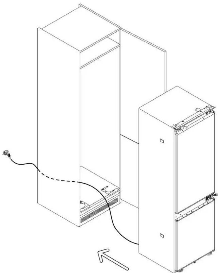
9.4 Built-in installation
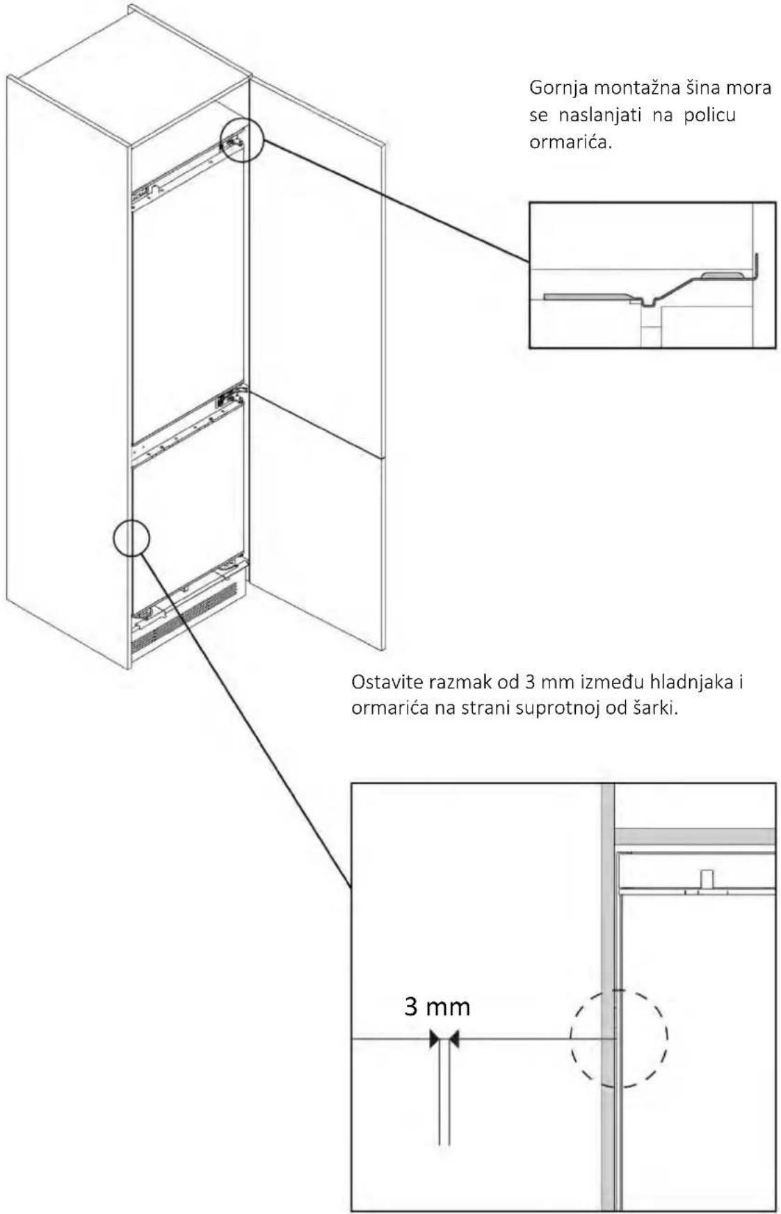
9 Refrigerator installation instructions
9.5 Securing the refrigerator feet
Remove the rod from the foot centering part. Adjust the desired height and secure the refrigerator feet to the cabinet using the provided screws.
9 Refrigerator installation instructions
9.7 Installing the lower covers
Attach the two lower covers and secure them as shown in the figure.
9 Refrigerator installation instructions
9 Refrigerator installation instructions
WELCOME
This installation instruction is intended for kitchen builders who will use these products. To ensure safety and achieve the best results, carefully read this instruction, including the safety instructions, and keep it for future reference. Before proceeding with the installation, note the serial number as it may be needed in case of repair. Check for any transport damage and consult a technician if you are unsure before use. Always keep all packaging material out of the reach of children.
i NOTE: Product features, images in the instruction, and additional equipment may vary depending on the purchased model.
Table of contents
Cable length 2270 mm
| Modeli | A (mm) | B (mm) | C (mm) | B (mm) | E (mm) | F (mm) | G (mm) |
| 1 | 540±2 | 550±2 | 1772±2 | 970 | 745 | 662 | 618 |
| 2 | 540±2 | 550±2 | 1935±2 | 1133 | 745 | 662 | 618 |
| 3 | 690±2 | 550±2 | 1935±2 | 1133 | 745 | 662 | 618 |
Dimensions in mm
Side view behind closed doors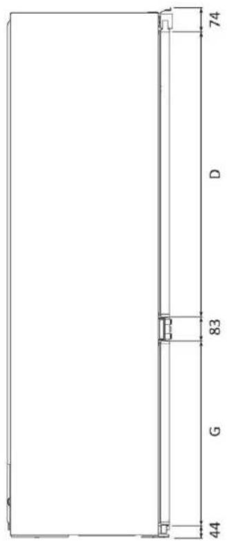
Floor plan
Side view with open doors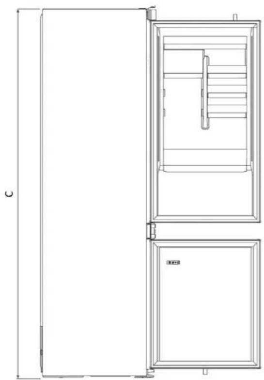
Floor plan
with open doors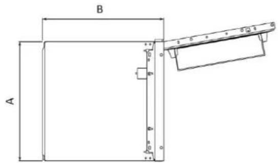
Required tools
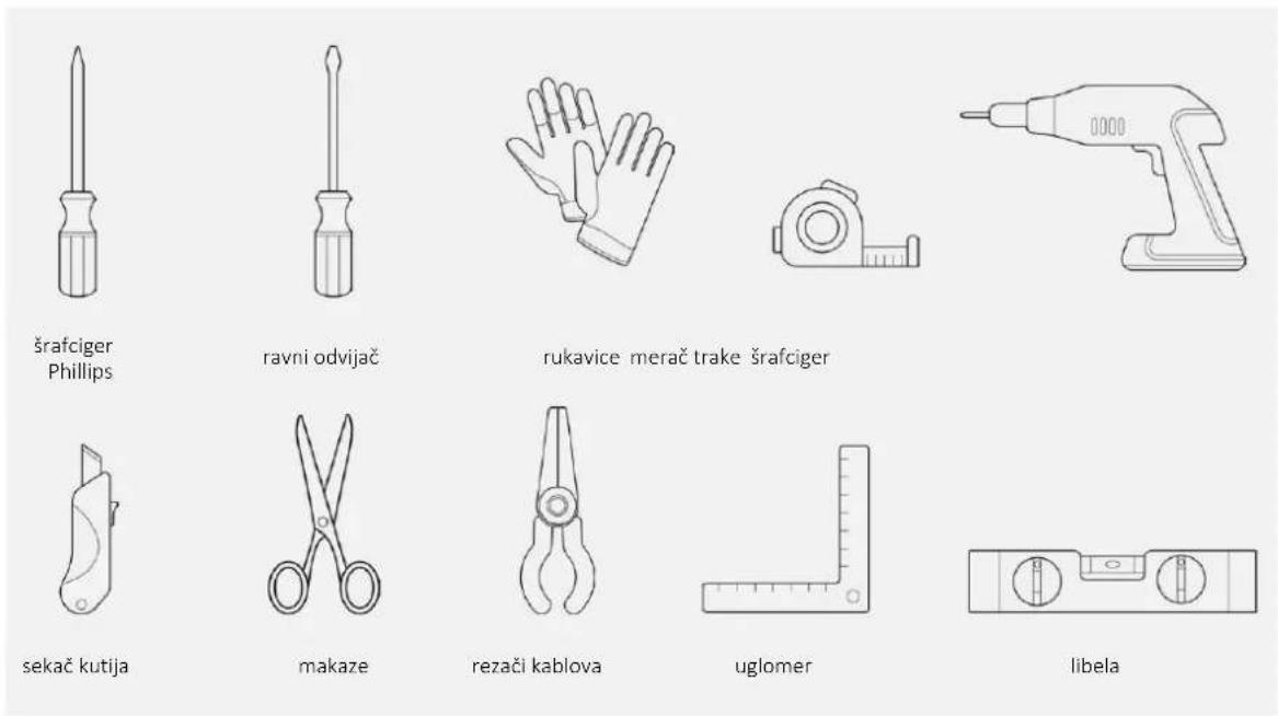
Supplied accessories

4 Installation tools
5.1 Preventive measures
- Provide a space for installation without a back wall.
- For product ventilation, follow the instructions in this manual.
- It is recommended to secure the appliance to the wall to prevent it from tipping over.
5.2 Dimensions in mm
Frontal axonometric view
with open door
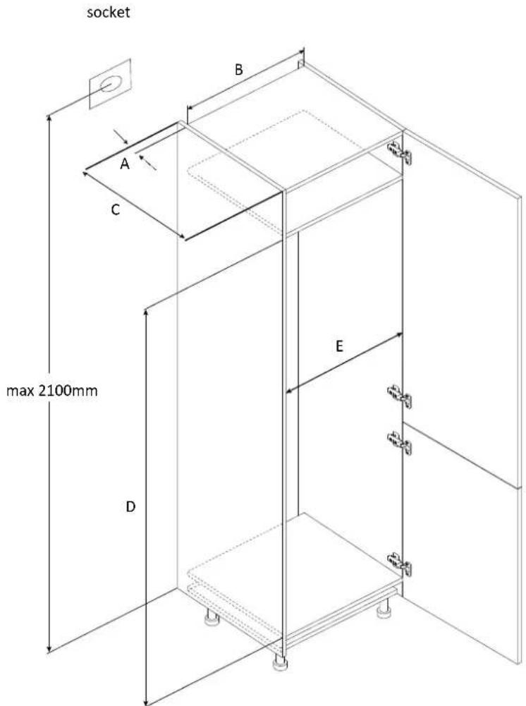
| Modeli | A (mm) | B (mm) | C (mm) | B (mm) | E (mm) | Posmatranje | |
| 1 | Min. | 50 | 400 | 560 | 1778 | 560 | Šarke: 17 mm |
| Preporučuje se | 580 | 1780 | 562 | ||||
| Maks | - | 1782 | 568 | ||||
| 2 | Min. | 50 | 400 | 560 | 1941 | 560 | |
| Preporučuje se | 580 | 1943 | 562 | ||||
| Maks | - | 1945 | 568 | ||||
| 3 | Min. | 50 | 400 | 560 | 1941 | 710 | |
| Preporučuje se | 580 | 1943 | 712 | ||||
| Maks | - | 1945 | 718 | ||||
9.3
Centering the refrigerator feet
![graph TD A["Step 1: Initial component"] --> B["Step 2: Tool placement"] B --> C["Step 3: Bracket assembly with dots on base"]](/content/2026/04/732472/images/ebded2c4ea738069c95f2c39a611082bd9478abc06242bd47b2e17f5c07313a1.jpg)
WARNING: Before inserting the refrigerator into the cabinet, route the power cord and temporarily secure it at the top with tape. Then, with two people, lift the product and place it into the recess, taking care not to damage the power cord. Ensure that the outlet is easily accessible.
9.4
9.4 Built-in installation
9.6
9.6
9.7 Installing the bottom covers
9.8
Applying the gaskets to the side of the refrigerator
Cut the gaskets to the appropriate size and stick them on the side of the refrigerator, opposite the hinges.
9.9 Installing the top covers and securing the refrigerator to the top shelf
Using the provided screws, attach the top front panel to the furniture shelf, then cover the top hinge and the opposite side with the covers.
WELCOME
cable length 2270 mm
| Modellek | A (mm) | B (mm) | C (mm) | D (mm) | E (mm) | F (mm) | G (mm) |
| 1 | 540±2 | 550±2 | 1772±2 | 970 | 745 | 662 | 618 |
| 2 | 540±2 | 550±2 | 1935±2 | 1133 | 745 | 662 | 618 |
| 3 | 690±2 | 550±2 | 1935±2 | 1133 | 745 | 662 | 618 |
Dimensions in mm
Top view
with doors open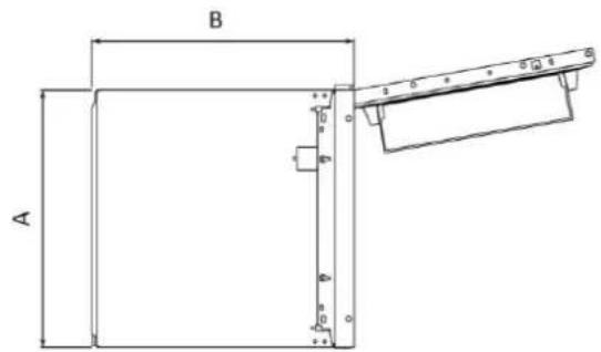
o this link
clicking
9.6
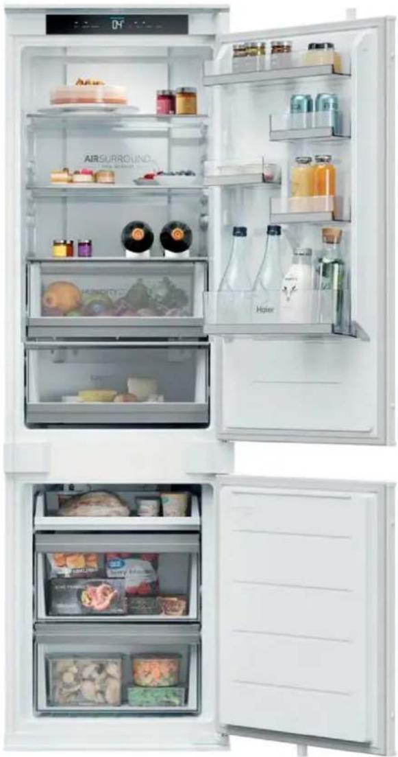
WELCOME
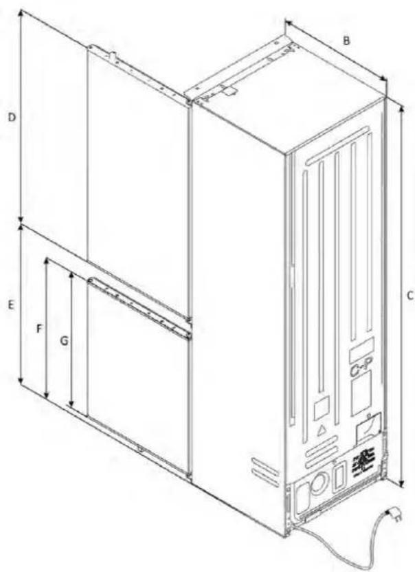
cable length 2270 mm
| Modeli | A (mm) | B (mm) | C (mm) | D (mm) | E (mm) | F (mm) | G (mm) |
| 1 | 540±2 | 550±2 | 1772±2 | 970 | 745 | 662 | 618 |
| 2 | 540±2 | 550±2 | 1935±2 | 1133 | 745 | 662 | 618 |
| 3 | 690±2 | 550±2 | 1935±2 | 1133 | 745 | 662 | 618 |
Dimensions in mm
Side view with doors closed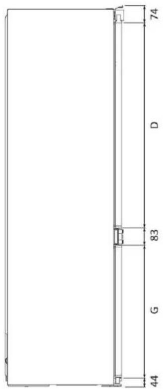
Top view
with doors closed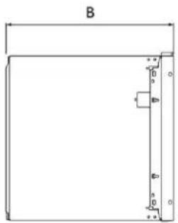
Top view
with doors open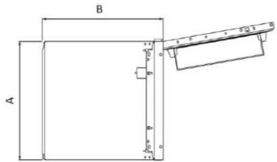
or by clicking on
this link
8 Change the door opening direction
8.1 Unlocking the door
9.3 Centering the refrigerator feet
![graph TD A["Step 1: Initial component"] --> B["Step 2: Tool placement"] B --> C["Step 3: Bracket assembly with dots and weights"]](/content/2026/04/732472/images/fc9e276b9c0d97a8b93ea6519394c927c50cd87c11518cce0b7df0f4479ca682.jpg)
9.4 Built-in installation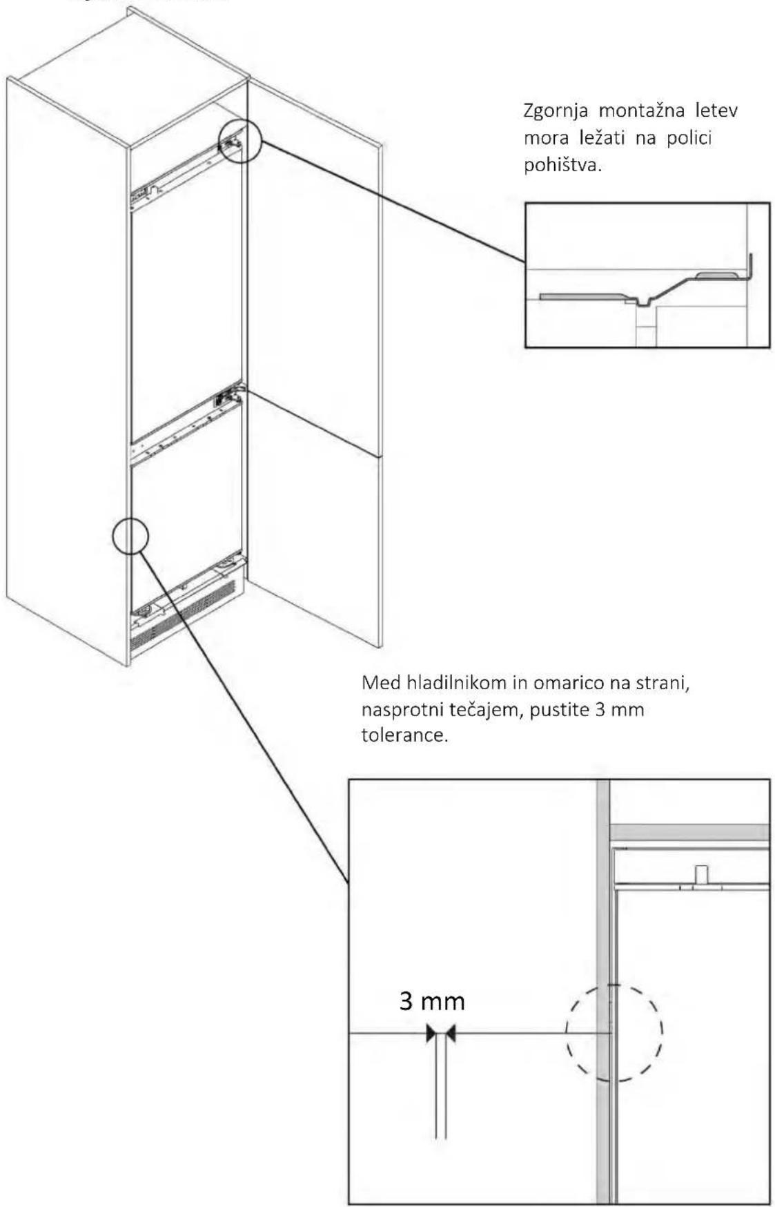
9.6
Installation of central supports and covers
9.7 Installation of bottom covers
WELCOME
cable length 2270 mm
| Modelky | A (mm) | B (mm) | C (mm) | D (mm) | E (mm) | F (mm) | G (mm) |
| 1 | 540±2 | 550±2 | 1772±2 | 970 | 745 | 662 | 618 |
| 2 | 540±2 | 550±2 | 1935±2 | 1133 | 745 | 662 | 618 |
| 3 | 690±2 | 550±2 | 1935±2 | 1133 | 745 | 662 | 618 |
Dimensions in mm
Side view
Side view
Top view
or by clicking
this link
9.6
10.1 Safety instructions
WELCOME
cable length 2270 mm
| Modele | A (mm) | B (mm) | C (mm) | D (mm) | E (mm) | F (mm) | G (mm) |
| 1 | 540±2 | 550±2 | 1772±2 | 970 | 745 | 662 | 618 |
| 2 | 540±2 | 550±2 | 1935±2 | 1133 | 745 | 662 | 618 |
| 3 | 690±2 | 550±2 | 1935±2 | 1133 | 745 | 662 | 618 |
Dimensions in mm
Top view
with doors open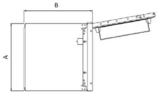
4 Installation tools
9.6
WELCOME
1 Safety warnings for installation
cable length 2270 mm
| A(mm) | Modeller | B(mm) | C(mm) | D(mm) | E(mm) | F(mm) | G(mm) | |
| 540±21 | 550±2 | 1772±2 | 970 | 745 | 662 | 618 | ||
| 540±22 | 550±2 | 1935±2 | 1133 | 745 | 662 | 618 | ||
| 690±23 | 550±2 | 1935±2 | 1133 | 745 | 662 | 618 |
Dimensions in mm
Top view
with doors open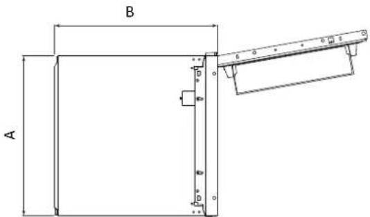
or by clicking
here link
WELCOME
9.4 Collection
Welcome
Cable length 2270 mm
| Modeller | A (mm) | B (mm) | C (mm) | D (mm) | E (mm) | F (mm) | G (mm) |
| 1 | 540 ±2 | 550 ±2 | 1772 ±2 | 970 | 745 | 662 | 618 |
| 2 | 540 ±2 | 550 ±2 | 1935 ±2 | 1133 | 745 | 662 | 618 |
| 3 | 690 ±2 | 550±2 | 1935 ±2 | 1133 | 745 | 662 | 618 |
Dimensions in mm
Side view
with doors closed
Top view
with doors closed

Side view
with doors open
Top view
with doors open
10.1 Warnings
Welcome
Cable length 2270 mm
| Modeller | A (mm) | B (mm) | C (mm) | B (mm) | E (mm) | F (mm) | G (mm) |
| 1 | 540±2 | 550±2 | 1772±2 | 970 | 745 | 662 | 618 |
| 2 | 540±2 | 550±2 | 1935±2 | 1133 | 745 | 662 | 618 |
| 3 | 690±2 | 550±2 | 1935±2 | 1133 | 745 | 662 | 618 |
Dimensions in mm
Sidovy
Sidovy
with open doors
Floor plan
with open doors
Necessary tools
or by clicking
WELCOME
Top view
with open doors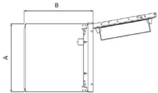
or by clicking on this
link
9.6
10.1 Warnings
PLEASE
This installation manual is intended for kitchen fitters who will use these products. To ensure safety and achieve the best results, carefully read this manual, including the safety instructions, and keep it for future reference. Before installation, record the serial number, as it may be needed in case of repairs. Make sure the product was not damaged during transport, and consult a technician if you have any doubts before use. Always store packaging materials out of reach of children.
NOTE. Product features, illustrations in the manual, and accessories may vary depending on the model purchased.
Contents
1 Safety instructions for installation p. 164 2 Where to install the product p. 165 3 Refrigerator dimensions p. 166 4 Tools for installation p. 168 5 Furniture dimensions p. 168 5.1 Precautions 5.2 Dimensions 6 Installation into furniture and ventilation p. 170 6.1 Installation in a column 7 Step-by-step installation video p. 171 8 Changing the door opening direction p. 172 8.1 Door opening 8.2 Removing the lower screw 8.3 Hinge inversion 8.4 Fixing the lower screw on the opposite side of the refrigerator 9 Refrigerator installation instructions p. 174 9.1 Installing the top plate for the refrigerator 9.2 Installing adhesive pads on the side of the refrigerator 9.3 Centering the refrigerator feet 9.4 Recessed installation 9.5 Securing the refrigerator feet 9.6 Installing central supports and covers 9.7 Installing lower covers 9.8 Installing pads on the side wall of the refrigerator 9.9 Installing upper covers and securing the refrigerator on the top shelf 9.10 Securing sliding hinges to furniture doors
Contents
10 Electrical connection p. 188 10.1 Warning 10.2 Other advice 11 User handover p. 190 12 Disassembling the product p. 190
1 Safety instructions for installation
Follow these instructions before starting to install the product.
Please follow these instructions before starting to install the product. Your safety is very important to us. Carefully read these instructions before using the product.
- Installation must be carried out by a qualified technician who knows and complies with the current legislation of the country of installation and the manufacturer's instructions;
- If manufacturer assistance is needed to remedy defects resulting from incorrect installation, such assistance is not covered by the warranty;
- Remove the packaging before using the appliance;
- After unpacking the product, check it for damage. If a problem arises, contact the service center before continuing installation, and do not connect it to the power supply;
- A damaged product can cause short circuits, electric shock, fire, and other hazards;
- Check whether the packaging contains any accessories or additional materials (bags with screws, documents, brochures, etc.), and if so, remove them and keep them;
- Before installing the device, make sure there is sufficient ventilation to ensure proper circulation of fresh air, necessary for cooling and protecting the internal components. Depending on the type of configuration, create the indicated openings as shown;
- If manufacturer assistance is required to remedy defects caused by incorrect installation, such assistance is not covered by the warranty. Follow the installation instructions intended for qualified personnel;
- Incorrect installation may damage property or injure people or animals. The manufacturer is not liable for such damage or injury;
- Safe use is guaranteed only if the device is correctly installed according to these instructions. In case of damage due to incorrect installation, the installer is responsible;
- During installation, it is recommended to use protective gloves to avoid cuts;
- The warranty does not cover damage caused by incorrect installation;
- In case of incorrect installation, modifications to the device's design, or improper connection, the product warranty becomes void;
- After installation, the power cord must not touch moving parts of kitchen cabinets (e.g., drawers) and must not be subjected to mechanical stress;
- This product requires continuous ventilation during use. Do not block the ventilation openings;
- After completing the installation, the technician must ensure that the device is installed correctly.
Important precautions
- Do not install the device in places exposed to direct sunlight, to avoid affecting its operation;
- Install and use this product in an enclosed, covered, dry, and well-ventilated room;
- Do not install the device outdoors where it is exposed to weather conditions; • Install the device near an electrical outlet; • Keep the device away from sources of fire;
- Place the appliance on a flat surface in a location suitable for its size and use;
- Clean the appliance with water and a mild detergent, then dry it with a soft cloth;
- The appliance is heavy; at least two people are needed to move it;
- After installation, let the refrigerator stand for at least 4 hours before switching it on, to stabilize the compressor oil.
This product is intended only for installation in household or similar environments, such as:
- staff kitchens in shops, offices, and other working environments;
- premises provided to staff and clients in hotels, motels, and other residential environments;
• beauty centers, guest rooms (B&B);
- for catering and similar applications, excluding retail. Install this product in a place where the ambient temperature is not lower or higher than the operating temperature indicated on the label: otherwise, the appliance may not work correctly.
- Extended moderate range (SN): "This appliance is intended for use at ambient temperatures from +10°C to +32°C";
- Moderate (N): "This appliance is intended for use at ambient temperatures from +16°C to +32°C";
- Subtropical (ST): "This appliance is intended for use at ambient temperatures from +16°C to +38°C";
- Tropical (T): "This appliance is intended for use at ambient temperatures from +16°C to +43°C".
3 Refrigerator dimensions
Dimensions in mm
Front axonometric view Rear axonometric view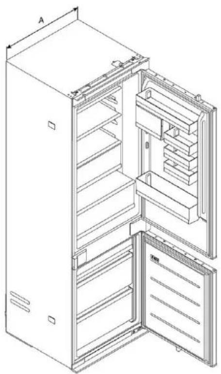
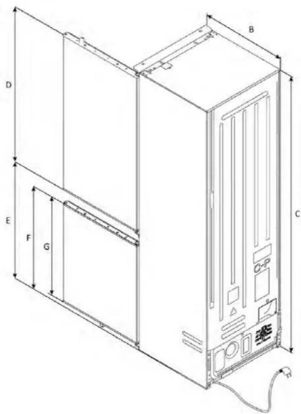
Cable length 2270 mm
| Modeli | A (mm) | B (mm) | C (mm) | D (mm) | E (mm) | F (mm) | G (mm) |
| 1 | 540±2 | 550±2 | 1772±2 | 970 | 745 | 662 | 618 |
| 2 | 540±2 | 550±2 | 1935±2 | 1133 | 745 | 662 | 618 |
| 3 | 690±2 | 550±2 | 1935±2 | 1133 | 745 | 662 | 618 |
Dimensions in mm
Side view
with door closed
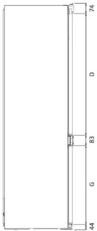
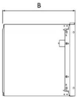
Top view
with door closed
Side view
Top view
Accessories supplied
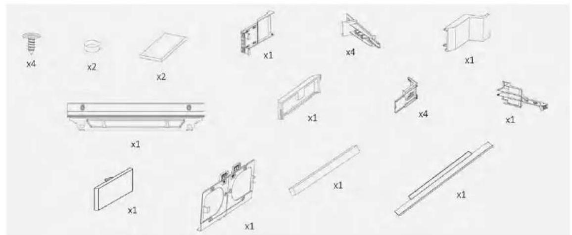
4 Installation tools
5.1 Safety precautions
- Plan a recessed niche without a back wall;
- Follow the instructions given in this manual regarding product ventilation;
- It is recommended to secure the device to the wall to prevent it from tipping over.
5.2 Dimensions in mm
Front axonometric view
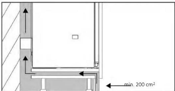
If it is not possible to create an opening in the plinth, it is necessary to find another solution to ensure good air circulation.
You can watch a video about product installation by scanning the QR code

or by going
to this
link
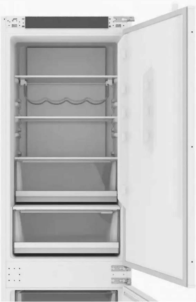
8 Changing the door opening direction
9.3 Centering the refrigerator feet
![graph TD A["1: Display panel with internal components"] --> B["2: Clear cleaning steps"] B --> C["3: Packaging assembly with hand icons and dots"]](/content/2026/04/732472/images/9a10736e3e0a5953efb20229f63a632037cc312248b5902358f3d2be00a3587f.jpg)
9 Installation instructions for the refrigerator
A WARNING: Before placing the refrigerator into the cabinet, route the power cord and temporarily secure it at the top with adhesive tape. Then lift the appliance with two people and insert it into the housing, being careful not to damage the power cord. Make sure the plug is freely accessible.
9.4 Recessed installation
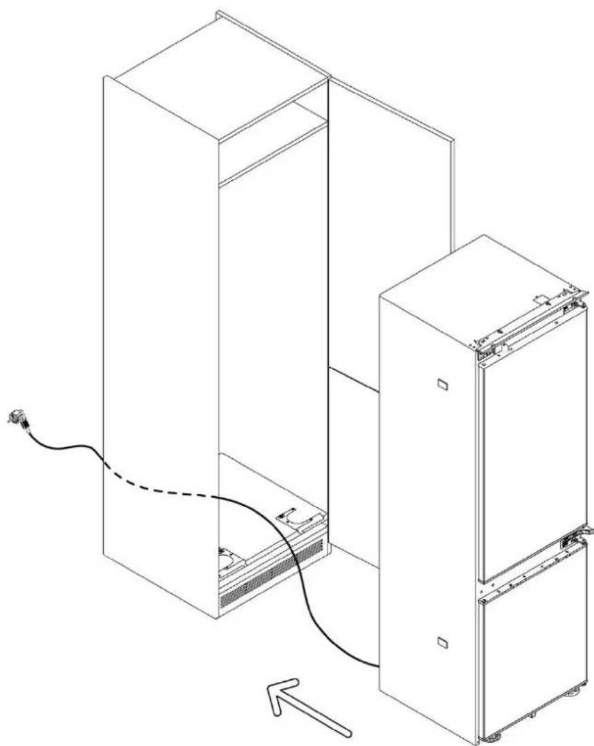
9.4 Recessed installation
9 Installation instructions for the refrigerator
9.5 Securing the refrigerator feet
Remove the rib from the central element of the foot. Adjust the required height and secure the refrigerator feet to the cabinet using the provided screws.
9.6 Installation of central supports and covers
Using the provided screws, attach the bracket to the side of the refrigerator opening. Remove the fixing insert. Finally, install the cover.
9 Installation instructions for the refrigerator
9.6
Installation of central supports and covers
Using the provided screws, attach the bracket to the side opposite the hinges. Remove the positioning lugs. Finally, install the cover.
9.7 Installation of lower covers
Install the two lower covers and secure them as shown in the diagram.
9 Installation instructions for the refrigerator
9.8 Installation of spacers on the side wall of the refrigerator
Cut the spacers to the required size and place them on the side of the refrigerator, opposite the hinges.
9.9 Installation of upper covers and securing the refrigerator to the top shelf
Using the provided screws, attach the upper front panel to the cabinet shelf, then cover the upper hinge and the opposite side with the covers.
9 Installation instructions for the refrigerator
9.10 Attaching sliding hinges to furniture doors
Before starting, make sure the cabinet doors and refrigerator doors are fully open at 90 degrees.
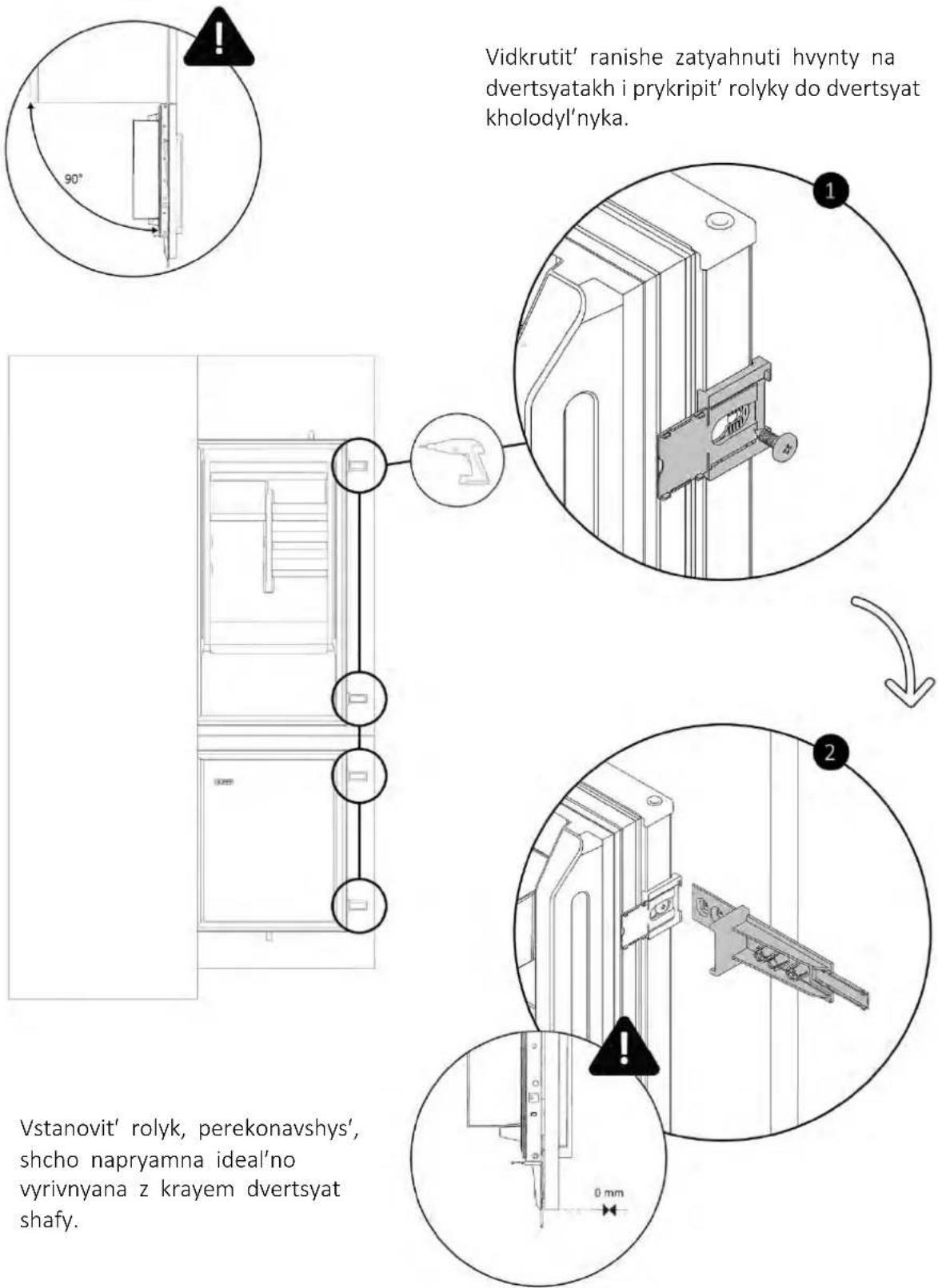
9.10 Attaching sliding hinges to furniture doors
Using a screwdriver, attach the rollers to the cabinet doors. Then remove the guides as shown in the diagram.
![graph TD A["Step 3: Initial assembly"] --> B["Step 4: Assembly with magnified inset"] B --> C["Final product image"]](/content/2026/04/732472/images/c3c574e6bcf84462ea0472b80f66600efaa2530871fafc8580e23d1098e0efd7.jpg)
10.1 Warnings
For safe connection of the appliance to the electrical mains, the following warnings must be observed:
- Any repair, installation, or maintenance performed incorrectly may seriously endanger the user;
- The manufacturer accepts no liability for direct or indirect damage caused by incorrect installation, repair, or maintenance.
- The company also accepts no liability for damage caused by the absence or interruption of the grounding system (e.g., electric shock);
- Connect the appliance exclusively using the supplied power cord;
- The appliance must be connected to an electrical system installed by a qualified professional;
- In case of damage caused by incorrect connection, the warranty is void;
- For any repair, contact only the customer support service and require the use of original spare parts;
- Disconnect the appliance from the power source before any intervention or maintenance
- To avoid the risk of fire or electric shock, do not damage the plug or power cord.
- Do not connect the appliance to extension cords, adapters, or portable power sources;
- When the appliance is installed in the chosen location, make sure that the power cord is not pinched or damaged, and that there are no extension cords or portable power units on the rear panel of the appliance.
Power consumption
See the product nameplate
Residual current device
It is recommended to use an automatic residual current circuit breaker (RCCB) whose tripping current complies with current standards.
WARNING: The product must be connected to the power supply through an all-pole disconnecting device that ensures contact separation and complies with overvoltage category III. Such a device must withstand maximum connection loads and comply with current standards.
- Make sure that the electrical characteristics on the nameplate match the power supply.
- The appliance operates on 220-240 V AC / 50 Hz.
- Abnormal voltage fluctuations may prevent the appliance from starting, damage the temperature regulator or compressor, and cause unusual noise during operation. In such a case, an automatic voltage regulator must be installed.
- Make sure that the power cable is not pinched under the appliance during and after transport/moving, to prevent it from being cut or damaged. If the appliance's power cord is damaged, do not continue installation and contact after-sales service.
- Make sure that the power source, socket, and fuses match the data on the technical data plate;
- Make sure that the socket is grounded, and do not use extension cords or adapters.

PRYMITKA (only for Great Britain): The appliance's power cord is equipped with
a 3-contact (grounding) plug that fits a standard 3-contact (grounding) outlet.
Never cut off or remove the third prong (ground). The outlet must remain accessible after installation.
10.2 Other tips
Using any household appliance requires following certain basic rules:
- It is recommended to keep the plug clean: any dirt residue on the plug can cause a fire;
- Do not pull the power cord to disconnect the appliance from the mains while it is operating;
- Do not touch the appliance with wet or damp hands or feet. It is not recommended to use adapters, extension cords, or power cords;
- In case of malfunction and/or reduced performance, turn off the device and do not touch it or make any modifications to it.
11 User transfer
WELCOME
Top view
with door open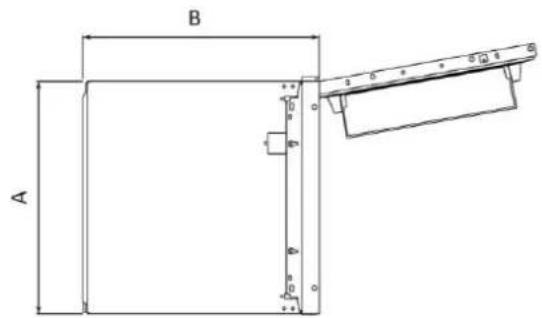
4 Installation tools
Required tools

or by clicking
this link
9.6
Hello
Cable length 2270 mm
| نماذج | A (mm) | B (mm) | C (mm) | D (mm) | E (mm) | F (mm) | G (mm) |
| 1 | 540±2 | 550±2 | 1772±2 | 970 | 745 | 662 | 618 |
| 2 | 540±2 | 550±2 | 1935±2 | 1133 | 745 | 662 | 618 |
| 3 | 690±2 | 550±2 | 1935±2 | 1133 | 745 | 662 | 618 |
Dimensions in mm
Side view
With doors closed
Side view
With doors open
Top view
With doors closed
Top view
With doors open
4 mounting tools
Required tools

this link
9.4 Installing the rest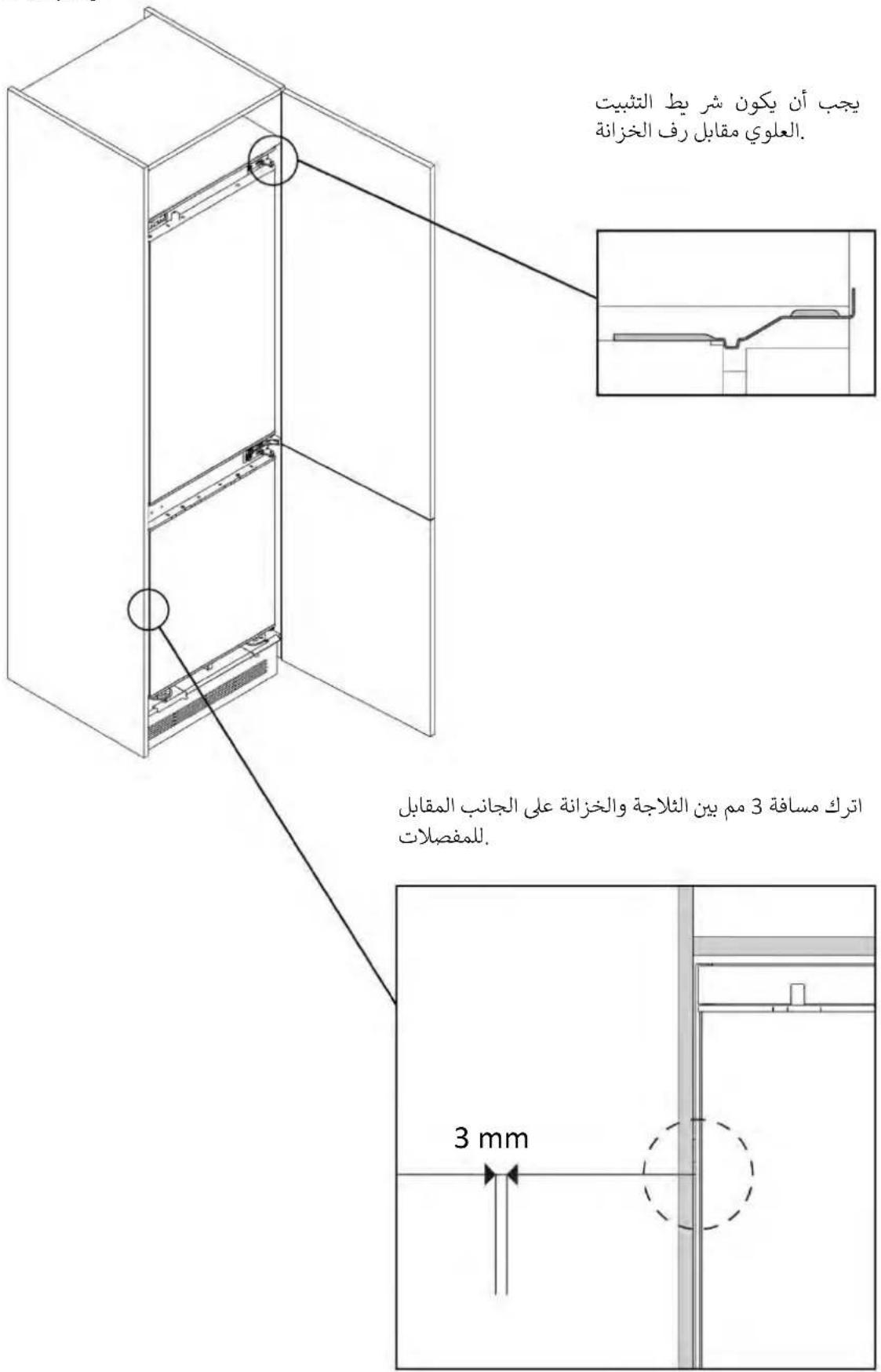
- WELCOME
- INDEX
- CONNECTION TO THE MAINS P
- DELIVERY TO THE USER P
- DISASSEMBLE THE PRODUCT P
- IMPORTANT WARNINGS
- THIS PRODUCT IS INTENDED SOLELY FOR INSTALLATION IN DOMESTIC OR SIMILAR ENVIRONMENTS, SUCH AS
- INSTALL THIS PRODUCT IN A LOCATION WHERE THE AMBIENT TEMPERATURE IS NOT LOWER OR HIGHER THAN THE OPERATING TEMPERATURE INDICATED ON THE PRODUCT LABEL: OTHERWISE, THE APPLIANCE WILL NOT FUNCTION CORRECTLY
- INSTALLATION TOOLS
- TOOLS NEEDED
- ACCESSORIES PROVIDED
- CABINET DIMENSIONS
- PRECAUTIONS
- DIMENSIONS IN MM
- FRONT AXONOMETRIC VIEW
- UNLOCKING THE DOORS
- REMOVING THE BOTTOM SCREW
- HINGES INVERSION
- ATTACHING THE BOTTOM SCREW ON THE OPPOSITE SIDE OF THE REFRIGERATOR
- INSTALLATION INSTRUCTIONS FOR THE REFRIGERATOR
- CENTERING THE REFRIGERATOR FEET
- BUILT-IN INSTALLATION (9.4)
- SECURING THE REFRIGERATOR FEET
- MOUNTING THE CENTRAL BRACKETS AND COVERS
- MOUNTING THE BOTTOM COVERS
- APPLYING GASKETS ON THE SIDE OF THE REFRIGERATOR
- MOUNTING THE TOP COVERS AND SECURING THE REFRIGERATOR TO THE UPPER SHELF
- ATTACHING THE SLIDING HINGES TO THE CABINET DOOR
- WARNINGS
- TO SAFELY PERFORM THE ELECTRICAL CONNECTION OF THE APPLIANCE, OBSERVE THE FOLLOWING WARNINGS
- POWER ABSORBED
- DIFFERENTIAL CIRCUIT BREAKER (LIFE-SAVING)
- OTHER ADVICES
- DELIVER TO THE USER
- DISASSEMBLE THE PRODUCT
- RECESS
- SIDE VIEW
- TOP VIEW
- RECESSED INSTALLATION
- INSTALLATION OF THE CENTRAL BRACKETS AND COVERS
- COLLECTION
- SAFETY PRECAUTIONS
- REFRIGERATOR INSTALLATION INSTRUCTIONS
- BUILT-IN INSTALLATION
- INSTALLING THE LOWER COVERS
- TABLE OF CONTENTS
- REQUIRED TOOLS
- SUPPLIED ACCESSORIES
- PREVENTIVE MEASURES
- FRONTAL AXONOMETRIC VIEW
- INSTALLING THE BOTTOM COVERS
- APPLYING THE GASKETS TO THE SIDE OF THE REFRIGERATOR
- INSTALLING THE TOP COVERS AND SECURING THE REFRIGERATOR TO THE TOP SHELF
- CHANGE THE DOOR OPENING DIRECTION
- UNLOCKING THE DOOR
- INSTALLATION OF CENTRAL SUPPORTS AND COVERS
- INSTALLATION OF BOTTOM COVERS
- SAFETY INSTRUCTIONS
- SAFETY WARNINGS FOR INSTALLATION
- SIDOVY
- FLOOR PLAN
- NECESSARY TOOLS
- PLEASE
- CONTENTS
- SAFETY INSTRUCTIONS FOR INSTALLATION
- IMPORTANT PRECAUTIONS
- THIS PRODUCT IS INTENDED ONLY FOR INSTALLATION IN HOUSEHOLD OR SIMILAR ENVIRONMENTS, SUCH AS
- REFRIGERATOR DIMENSIONS
- ACCESSORIES SUPPLIED
- CHANGING THE DOOR OPENING DIRECTION
- INSTALLATION OF LOWER COVERS
- INSTALLATION OF SPACERS ON THE SIDE WALL OF THE REFRIGERATOR
- INSTALLATION OF UPPER COVERS AND SECURING THE REFRIGERATOR TO THE TOP SHELF
- ATTACHING SLIDING HINGES TO FURNITURE DOORS
- FOR SAFE CONNECTION OF THE APPLIANCE TO THE ELECTRICAL MAINS, THE FOLLOWING WARNINGS MUST BE OBSERVED
- POWER CONSUMPTION
- RESIDUAL CURRENT DEVICE
- OTHER TIPS
- USER TRANSFER
- HELLO
- MOUNTING TOOLS
Brand : HOOVER
Model : HONBQT3518E
Category : Refrigerator