ERLV185-60hib1 - Fridge Essentiel B - Free user manual and instructions
Find the device manual for free ERLV185-60hib1 Essentiel B in PDF.

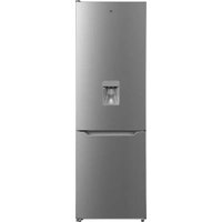
| Type de produit | 1-door refrigerator |
| Marque | Essentiel B |
| Modèle | ERLV185-60hib1 |
| Nombre de portes | 1 |
| Inversion du sens d'ouverture | Possible (procedure described in the manual) |
| Outils nécessaires pour inversion | Flathead screwdriver, Phillips screwdriver, 8 mm socket wrench |
| Clayettes | Removable glass shelves |
| Balconnets | Yes, removable |
| Pieds réglables | Yes, front leveling feet |
| Poignée | Raised, removable for reversal |
| Protection environnementale | Recyclable appliance (WEEE) |
| Sécurité d'installation | Unplug before any intervention, do not lay the appliance flat on its back |
| Entretien courant | Clean the interior with a damp cloth, defrost if necessary |
| Documents fournis | User manual (36 pages) available for download |
| Assistance | Possibility to ask questions online via notice-facile.com |
Frequently Asked Questions - ERLV185-60hib1 Essentiel B
User questions about ERLV185-60hib1 Essentiel B
0 question about this device. Answer the ones you know or ask your own.
Ask a new question about this device
Download the instructions for your Fridge in PDF format for free! Find your manual ERLV185-60hib1 - Essentiel B and take your electronic device back in hand. On this page are published all the documents necessary for the use of your device. ERLV185-60hib1 by Essentiel B.
USER MANUAL ERLV185-60hib1 Essentiel B
natural_image
Front view of a white refrigerator with a black indicator light on top (no visible text or symbols)natural_image
Technical illustration showing two steps of a mechanical assembly: one with a tool and directional arrows, the other with a hand holding a tool (no text or symbols present)natural_image
Diagram of a vehicle parking lot with a downward arrow indicating direction (no text or symbols)natural_image
Technical line drawing of a structural assembly with layered components (no text or symbols)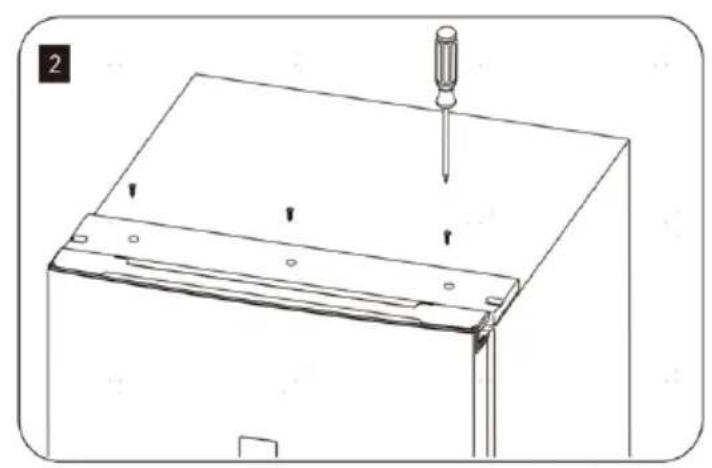
natural_image
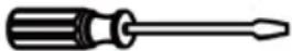
Line drawing of a screwdriver inserted into a flat panel with mounting holes (no text or symbols)You can reverse the opening direction of your refrigerator door. We recommend that 2 persons work together to reverse the door.
WARNING!
- When reversing the opening direction of the door, the appliance must not be connected to the mains. Ensure that the plug is removed from the mains socket.
- Ensure the unit is empty before reversing.
- It is necessary to tilt the unit backwards before performing the reversing procedure. You should lean the unit on something sturdy for support, e.g. on a chair just below the top panel of the unit.
- Do not lay the unit flat on its back as this may damage the coolant system.
- All parts removed must be saved for re-installation of the door.
We recommend that you contact a qualified technician for performing the procedure. You should only try to reverse the door yourself if you believe you are able to do so.
Tools you will need:
 | Thin-blade screwdriver |  | Crosshead screwdriver |
 | 8 mm socket driver |
NOTES:
- Take a photo of the wiring inside of the hinge cover as this will help you to re-wire the refrigerator later on in the process.
-
All descriptions using left and right are taken from the perspective of a person standing in front of the refrigerator when it is in an upright position.
-
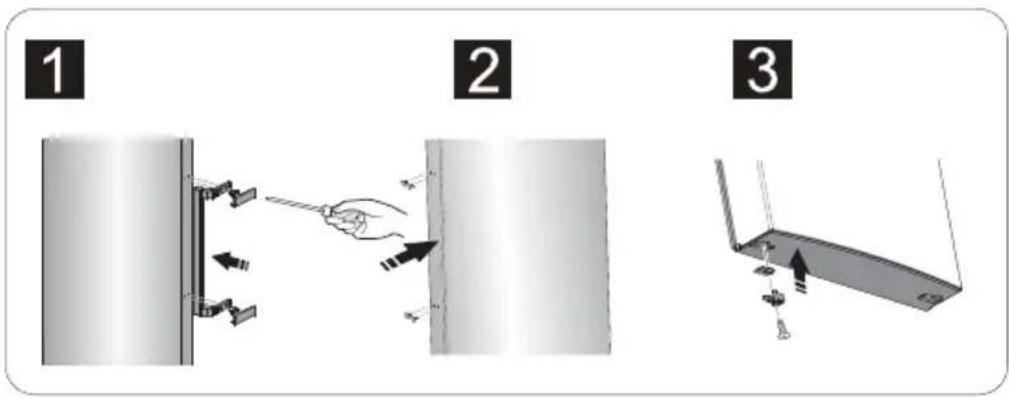
Stand the refrigerator upright. Take out all the glass shelves and racks,
-
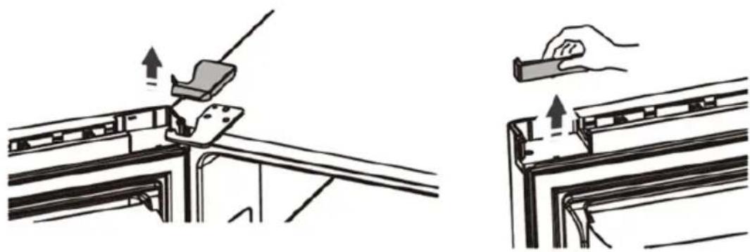
Remove the upper cover (1) on top of the refrigerator body.
Remove the corner cover (4) and the upper cover of the door (3).
Remove the upper hinge cover (2) and store it away for further use (see Step 4).
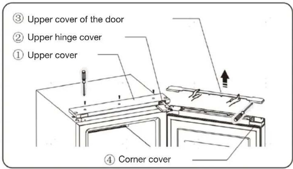
NOTE: Upper hinge cover has left and right side. The upper hinge cover packed as an accessory is for the left side.
natural_image
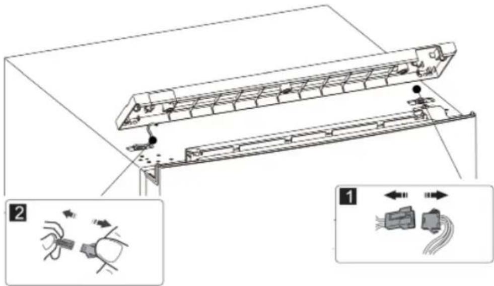
Technical illustration showing two mechanical assembly steps: one with a tool and directional arrows, the other with a hand holding a tool (no text or symbols present)- Disconnect the electrical connectors.
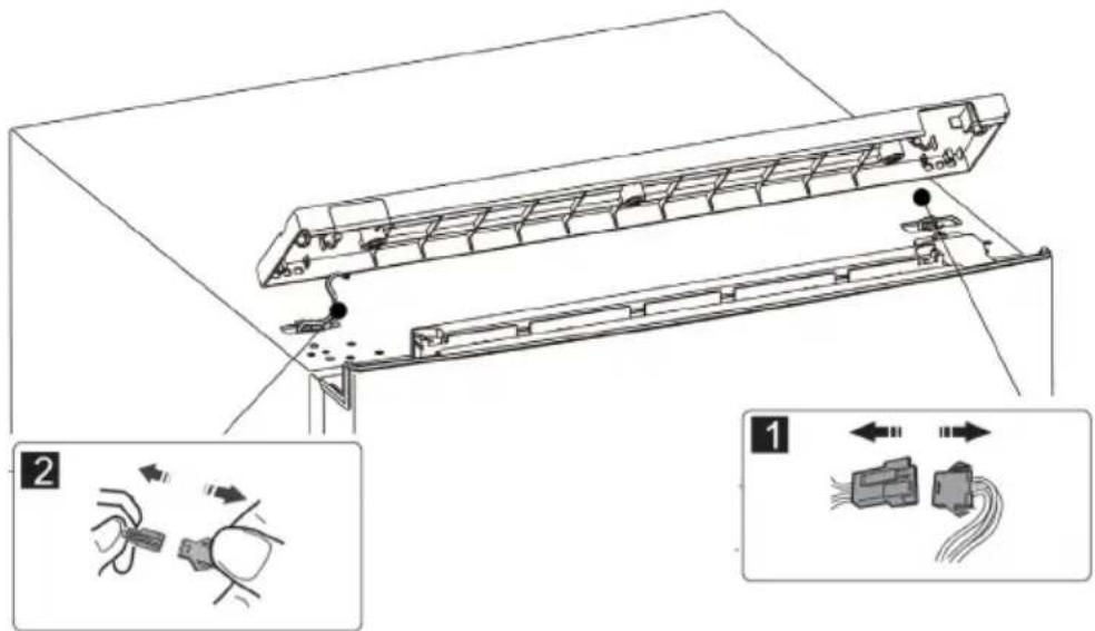
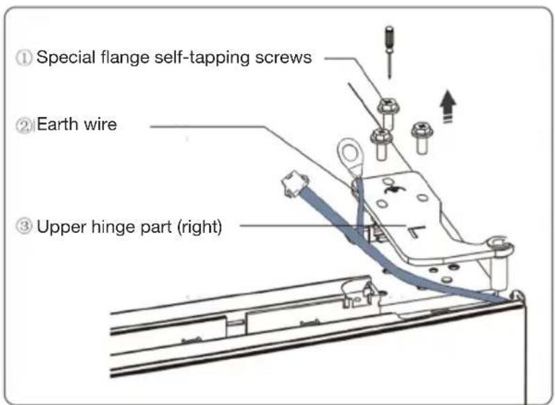
- Remove the special flange self-tapping screws (1), loosen the earth wire (2) and remove the upper hinge part (3) on the right.
NOTE: Hold the door by the hand when performing this step to prevent the door from dropping.
- Remove the door and place it on a smooth surface with its panel upwards.
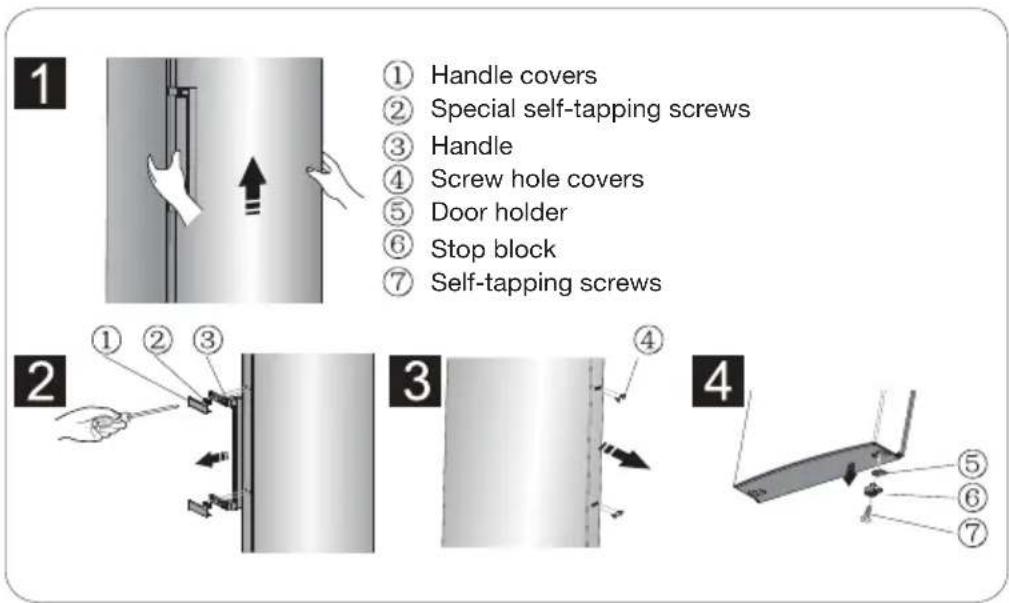
Lever the handle covers (1) and the screw hole covers (4).
Loosen the special self-tapping screws (2).
Change the handle (3) to the right side.
Install the special self-tapping screws (2), the handle covers (1) and the screw hole covers (4) in turn.
Loosen the self-tapping screws (7), detach the stop block (6) and door holder (5).
Turn the stop block (6) over, and then install the door holder (5) and the stop block (6) to the left side with the self-tapping screws (7).
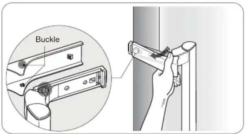
NOTE 1: Remove the handle cover as shown in the following image: Bend the upper wing and take the upper buckle apart from the handle. Perform the same to the other side, and then remove the handle cover.
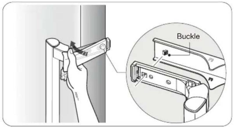
NOTE 2: Install the handle cover as shown in the following image: Button the buckle, and then close the cover until it clicks into place.
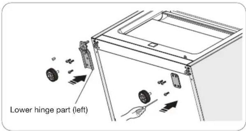
- Lay the refrigerator flat on the ground, and then remove the adjustable levelling feet part (3), and then loosen the self-tapping screws (4).
Remove the front foot fixed board (2) and the right lower hinge part (1).
Loosen the screws in the lower hinge part (1), and then change it to the near screw hole. Then, fasten the screw and mount the washer.
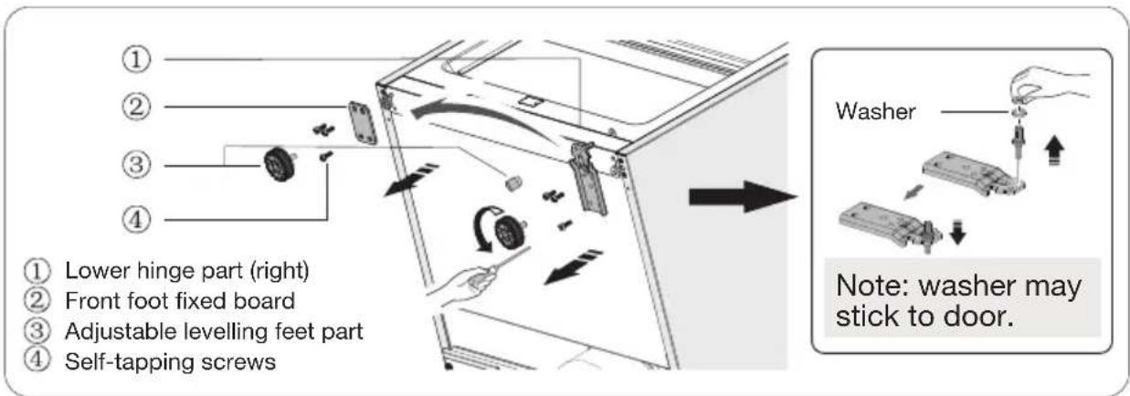
- Change the lower hinge part (1) to the left side, and the front foot fixed board to the right side.
Fasten the self-tapping screws (4).
Finally, install the adjustable levelling feet (3).
- Position the door, and then align the left upper hinge part (1) provided in the package with the door. Move the connecting wires (2) in the slot of the door from right to left. Fix the left upper hinge part (1) and the connecting wires (2) with the screws (3).
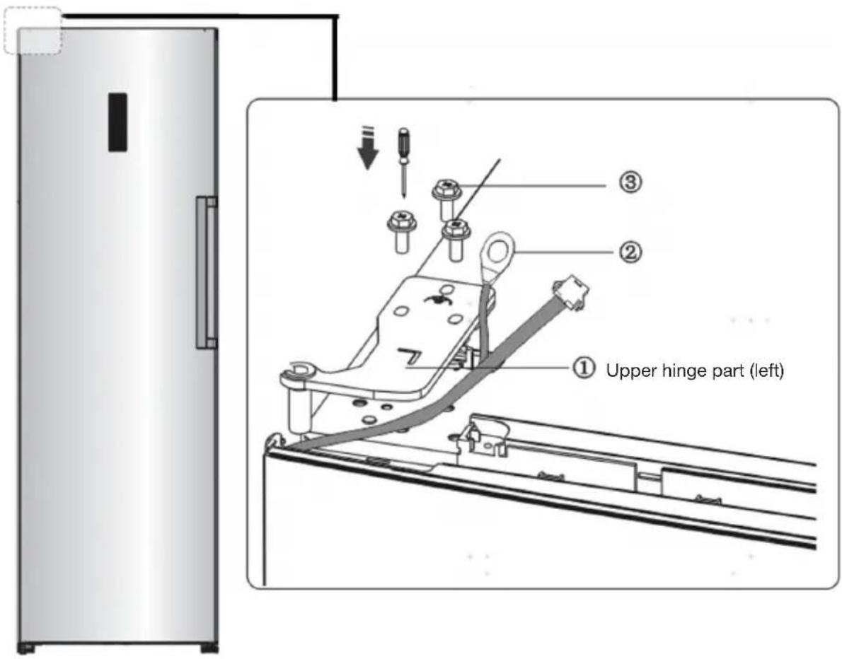
NOTE: Hold the door by the hand when installing.
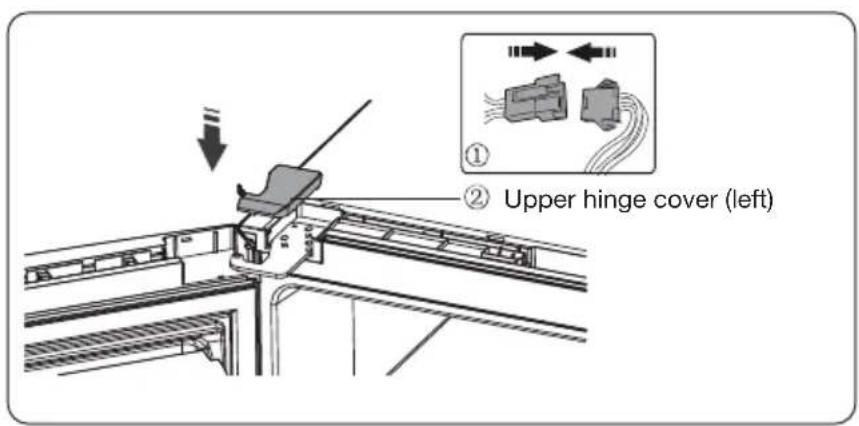
- Connect the electrical connector (1) in accordance with step 3, and then install the left upper hinge cover (2) provided in the package.
- Reverse the corner cover by 180^ and install it onto the right corner of the door. Mount the upper cover on top of the fridge door.
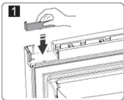
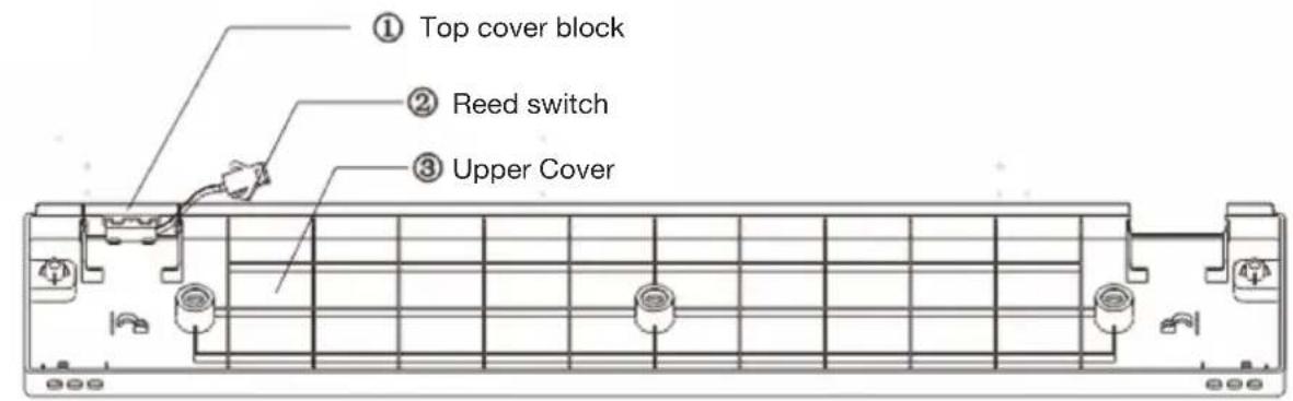
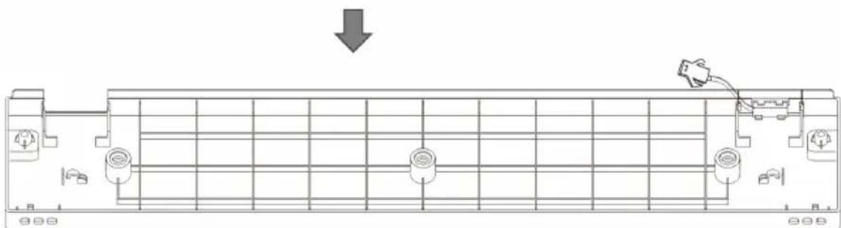
- Take the top cover block (1) out from the Upper Cover (3) and install it onto the other side of the Upper Cover.
natural_image
Architectural floor plan showing room layout and equipment placement (no text or labels)NOTE: Ensure the reed switch (2) fits well with the top cover block.
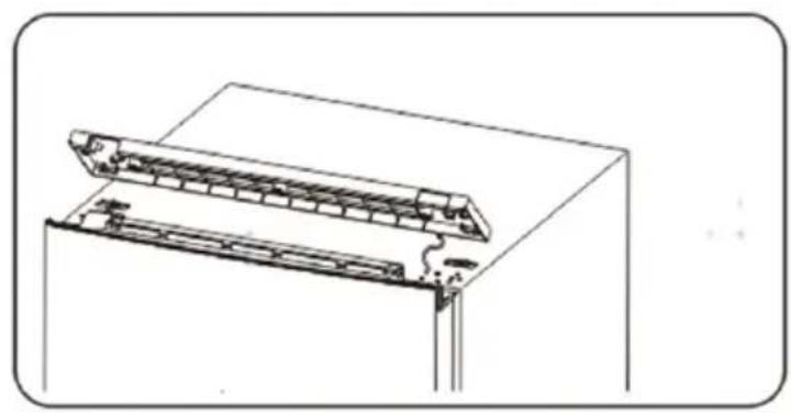
- Connect the wire connector. Install the upper cover on top of the fridge.
natural_image
Technical line drawing of a structural assembly with layered components (no text or symbols)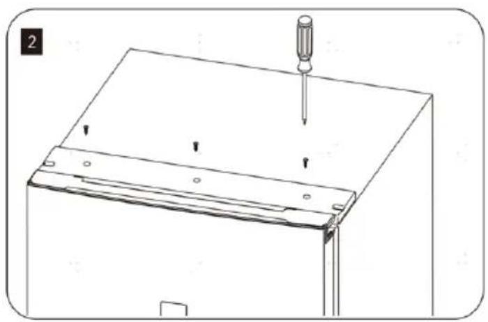
natural_image
Technical line drawing of a mechanical assembly with a screwdriver inserted, showing mounting brackets and a base plate (no text or symbols)- Place the glass shelves and racks back to the refrigerator.
natural_image
Technical illustration showing two steps of a mechanical assembly: one with a tool and directional arrows, the other with a hand holding a tool (no text or symbols present)natural_image
Illustration of a hand holding a clip above a rack with a downward arrow indicating a drop or compression (no text or symbols present)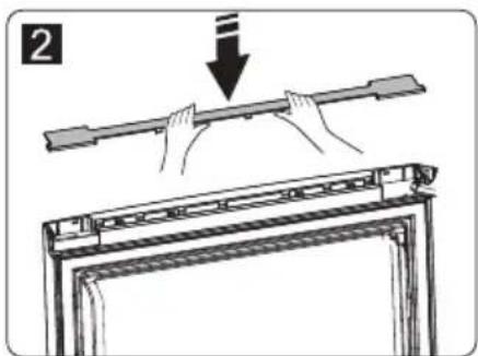
natural_image
Diagram of a vehicle parking garage with a downward arrow indicating direction (no text or symbols)natural_image
Technical line drawing of a mechanical assembly with no visible text or symbols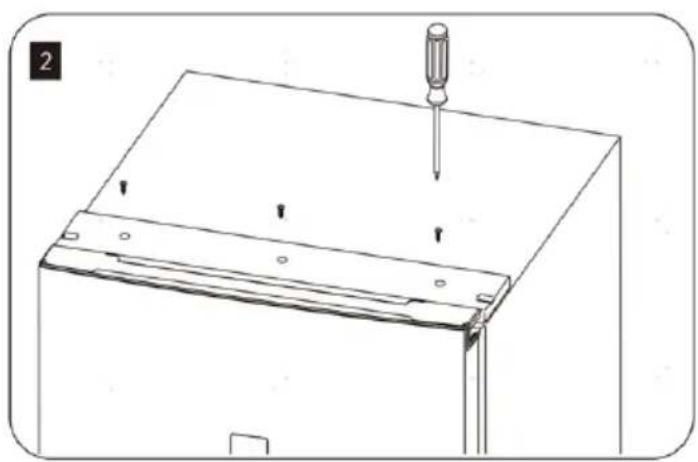
natural_image
Technical line drawing of a mechanical assembly with a screwdriver inserted, showing mounting brackets and a base plate (no text or symbols)natural_image
Technical illustration showing two steps of a mechanical assembly: one with a clamp and directional arrows, the other with a hand holding a tool (no text or symbols present)- Koppel de elektrische connectoren los.
natural_image
Diagram of a vehicle chassis with a downward arrow indicating motion or movement (no text or symbols present)natural_image
Technical line drawing of a mechanical assembly with no visible text or symbols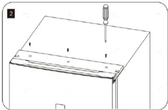
natural_image
Technical line drawing of a mechanical assembly with a screwdriver inserted, showing mounting brackets and a base plate (no text or symbols)All information, designs, drawings and pictures in this document are the property of SOURCING & CREATION. SOURCING & CREATION reserves all rights to its brands, designs and information. Any copy and reproduction through any means shall be deemed and considered as counterfeiting.
Protection of the environment
This symbol attached to the product means that it is an appliance whose disposal is subject to the directive on waste from electrical and electronic equipment (WEEE). This appliance may not in any way be treated as household waste and must be subject to a specific type of removal for this type of waste. Recycling and recovery systems are available in your area (waste removal) and by distributors.
By taking your appliance at its end of life to a recycling facility, you will contribute to environmental conservation and prevent any harm to your health.

Umweltschutz
\* Tested in our laboratories
Warranty valid from the date of purchase (receipt as proof of purchase). This warranty does not cover defects or damage caused by improper set up, incorrect use, or normal wear and tear of this product.
\* In unseren Labors getestet
SERVICE RELATION CLIENTS / Customer Relations Department / Kundenservice / Klantenafdeling
Avenue de la Motte CS 80137 59811 Lesquin cedex
FABRIQUÉ EN R.P.C. / Made in China / Hergestellt in VR China / Gefabriceerd in VRC.
SOURCING & CREATION Avenue de la Motte 59810 Lesquin - FRANCE contact@sc-ub.com