AMTRON 4You 560 11 - Electric charger Mennekes - Free user manual and instructions
Find the device manual for free AMTRON 4You 560 11 Mennekes in PDF.

User questions about AMTRON 4You 560 11 Mennekes
0 question about this device. Answer the ones you know or ask your own.
Ask a new question about this device
Download the instructions for your Electric charger in PDF format for free! Find your manual AMTRON 4You 560 11 - Mennekes and take your electronic device back in hand. On this page are published all the documents necessary for the use of your device. AMTRON 4You 560 11 by Mennekes.
USER MANUAL AMTRON 4You 560 11 Mennekes
Operating and installation manual
natural_image
Line drawing of a Minibus device with coiled cable and connector (no text or symbols)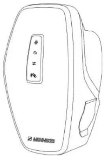
natural_image
Line drawing of a rectangular device with a control panel and a logo (no text or symbols on the device itself)Inhaltsverzeichnis
3.7 Ladeanschlüsse.... 13
6.11 Front Cover anbringen 40
text_image
① ② ③ ④ ⑤ ⑥ MISHEEStext_image
Technical diagram of an electronic device with numbered components for identificationtext_image
1. α = ~45° α 2xAbb. 4: Front Cover lösen - 1
text_image
2.Abb. 5: Front Cover lösen - 2
natural_image
Line drawing of a handheld electronic device with cables and connectors (no text or symbols)text_image
Technical diagram of a device interior with labeled components and numbered annotationnatural_image
Technical diagram of a car electrical connector with color-coded wires and cable (no text or labels)text_image
Technical diagram of a car interior with numbered components and highlighted areastext_image
Diagram of a device rear panel with three labeled buttons: star, ex, and ≠text_image
Technical diagram of a vehicle interior with labeled components and numbered annotationtext_image
Technical diagram of a car interior with labeled components and directional arrow indicating movement or flowtext_image
Technical diagram of a vehicle electrical panel with numbered components and highlighted areasnatural_image
Line drawing of a device with multiple cables and connectors, no text or symbols presentnatural_image
Line drawing of a device rear panel with a switch and cable, no text or symbols present6.11 Front Cover anbringen
text_image
Diagram illustrating a medical device with warning indicators and a magnified view showing the process.Abb. 21: Front Cover anbringen - 1
text_image
2. clickAbb. 22: Front Cover anbringen - 2
natural_image
Line drawing of a device's front panel with a red circle highlighting a specific area (no text or symbols present)text_image
Technical diagram of an engine component with numbered parts and directional arrow indicating rotation or assembly.2 For your safety.... 3
2.1 Target groups 3
2.2 Intended use 3
2.3 Improper use.... 3
2.4 Basic safety information.... 4
2.5 Safety signs 4
3 Product description...... 6
3.1 Main features 6
3.2 Rating plate 7
3.3 Delivery contents....7
3.4 Product structure 8
3.5 Charging modes....8
3.6 LED status display....9
3.7 Charging connections 11
4 Technical data.... 12
5 Installation.... 14
5.1 Select location 14
5.1.1 Permissible ambient conditions.... 14
5.2 Preparatory work on site.... 14
5.2.1 Upstream electrical installation.... 14
5.2.2 Protective devices 15
5.3 Transporting the product.... 15
5.4 Detach front cover.... 16
5.5 Opening the product.... 16
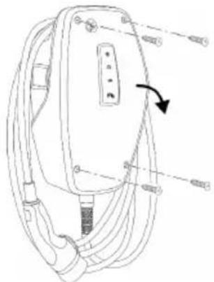
5.6 Installing the product on the wall 16
5.6.1 Creating drill holes 16
5.6.2 Prepare the cable entry point.... 17
5.6.3 Installing the product 18
5.7 Electrical connection.... 19
5.7.1 Network configurations.... 19
5.7.2 Power supply 19
5.7.3 Shunt release 20
5.8 Surge protection equipment.... 20
6 Commissioning 21
6.1 Switching on the product.... 21
6.2 Checking the mains supply.... 21
6.3 Establishing a network connection for initial start-up 21
6.4 Establishing a connection with the AMTRON® 4 installers app for configuration .... 22
6.4.1 User roles.... 23
6.4.2 Set-up Wizard 23
6.5 Integrating the product into a local network.... 23
6.6 Establishing a connection with the AMTRON® 4Drivers app.... 24
6.7 Managing RFID cards.... 25
6.8 Use cases.... 25
6.8.1 Downgrade 25
6.8.2 Connecting an external energy meter ..... 27
6.8.3 Blackout protection 30
6.8.4 "Solar charging" and "Customised charging" modes 30
6.8.5 Energy management system 32
6.8.6 Connecting to a backend system.... 34
6.8.7 Load management in charging point networks.... 34
6.9 Testing the product 35
6.10 Closing the product.... 36
6.11 Attaching the front cover 36
6.12 Attach charging point labelling 37
7 Operation....38
7.1 AMTRON® 4Drivers app.... 38
7.2 Authorisation 38
7.3 Charging the vehicle.... 38
8 Servicing.... 41
8.1 Maintenance.... 41
8.1.1 Maintenance work 41
8.2 Cleaning 41
8.3 Firmware update 41
9 Troubleshooting 43
9.1 Spare parts.... 43
9.2 Unlocking the charging plug manually..... 43
10 Taking out of service 45
10.1 Storage 45
10.2 Disposal 45
11 EU Declaration of Conformity...... 46
1 About this document
The charging station is hereinafter referred to as "product". This document applies to the following product variants:
■ AMTRON® 4You 510 11
■ AMTRON® 4You 510 22
■ AMTRON® 4You 560 11
■ AMTRON® 4You 560 22
Firmware version of the product: 1.3
This document provides information for the qualified electrician and the operator. It contains important instructions for the installation and proper use of the product.
Copyright ©2025 MENNEKES Elektrotechnik GmbH & Co. KG
1.1 Website
www.mennekes.org/emobility

1.2 Contact
To contact MENNEKES directly, please use the form on our website under "Contact".
“1.1 Website” [▶ 2]
1.3 Warning notices
Warning of personal injury
DANGER
This warning notice indicates imminent danger that will result in death or severe injuries.
WARNING
This warning notice indicates a dangerous situation that can result in death or severe injuries.
CAUTION
This warning notice indicates a dangerous situation that can result in minor injuries.
Warning of material damage
ATTENTION
This warning notice indicates a dangerous situation that can result in material damage.
1.4 Symbols used

The activities marked with this symbol may only be carried out by a qualified electrician.

This symbol indicates an important note.

This symbol indicates additional, useful information.
√ This symbol indicates a requirement.
This symbol indicates a call for action.
→ This symbol indicates a result.
■ This symbol indicates a listing.
This symbol is used to refer to another document or another passage in this document.
2 For your safety
2.1 Target groups
This document provides information for the qualified electrician and the operator. Knowledge of electrical engineering is required for certain tasks. These tasks, which are identified by the “qualified electrician” symbol, should only be carried out by a qualified electrician.
“1.4 Symbols used” [▶ 2]
Operators
The operator is responsible for ensuring compliance with the intended use of the product and its safe operation. This also includes instructing persons who use the product. The operator is responsible for ensuring that tasks that require specialist knowledge are completed by an accordingly qualified professional.
Qualified electricians
A qualified electrician is a person who, based on his or her professional education, knowledge and experience as well as knowledge of relevant provisions, can assess the work assigned to him or her and identify possible hazards.
2.2 Intended use
The product is intended for use in private areas.
The product is intended exclusively for the charging of electric and hybrid vehicles, hereinafter referred to as “vehicle”.
■ Charging according to Mode 3 pursuant to IEC 61851 for vehicles with non-gassing batteries.
■ Plugs and sockets according to IEC 62196.
Vehicles with gassing batteries cannot be charged. The product is intended exclusively for permanent wall mounting or mounting on a stand system provided by MENNEKES, for indoor and outdoor use.
In some countries, there is a requirement for a mechanical switching element to disconnect the charging point from the mains if a load contact on the product is welded (welding detection). The requirement can be implemented, for example, by means of a shunt release.
Legal requirements in some countries provide for additional protection against electric shock. One possible additional protective measure is the use of a shutter.
The product may only be operated taking into account all international and national regulations. Observe the following international regulations or the respective national transposition:
IEC 61851-1
IEC 62196-1
IEC 60364-7-722
IEC 61439-7
The product meets the European normative minimum requirements for charge point labelling according to EN 17186 when the charge point labelling sticker is attached to the product. Depending on the installation location (e.g. semi-public area) and the national requirements of the country of use, further information may need to be added.
Read, observe and retain this document and all additional documents for this product and, if necessary, pass them on to the subsequent operator.
2.3 Improper use
Using the product is safe only when used as intended. Any other use or changes to the product are considered improper use and therefore not permitted.
The operator, qualified electrician or user is responsible for any personal injury or material damage arising from improper use. MENNEKES Elektrotechnik GmbH & Co. KG accepts no liability for any consequences arising from improper use.
2.4 Basic safety information
Knowledge of electrical engineering
Knowledge of electrical engineering is required for certain tasks. These tasks, which are identified by the “qualified electrician” symbol, must only be carried out by a qualified electrician.
“1.4 Symbols used” [▶ 2]
People can be seriously injured or killed if work that requires knowledge of electrical engineering is carried out by electrical laypersons.
▶ Arrange for work that requires knowledge of electrical engineering to be carried out only by a qualified electrician.
Pay attention to the symbol “Qualified electrician” in this document.
Do not use a damaged product
People can be seriously injured or killed if a damaged device is used.
▶ Do not use a damaged product.
▶ Mark a damaged product to ensure that no one uses it.
▶ Arrange for a qualified electrician to rectify the damage without delay.
▶ Take the product out of service if necessary.
Carry out maintenance properly
Improper maintenance can affect the safety of the product and cause accidents. This can seriously injure or kill people.
▶ Carry out maintenance properly.
“8.1 Maintenance” [▶ 41]
Pay attention to supervisory duties
Individuals who are not fully able to assess potential hazards as well as animals pose a danger to themselves and others.
▶ Keep persons at risk away from the product, e.g. children.
▶ Keep animals away from the product.
Properly use the charging cable
Improper handling of the charging cable can cause hazards such as electric shock, short circuit or fire.
▶ Avoid loads and impacts.
▶ Do not pull the charging cable over sharp edges.
▶ Avoid knotting or kinking the charging cable.
▶ Do not use adapter plugs or extension cables.
▶ Do not expose the charging cable to tensile stress.
▶ Grasp the charging cable at the charging plug, and pull it out of the charging socket.
▶ After using the charging cable, put the protective cap on the charging plug.
2.5 Safety signs
Safety signs that warn of hazardous situations are affixed on some of the product components. Failure to heed the safety signs may result in serious injury or death.
Safety signs Meaning
Danger – high voltage.
▶ Prior to working on the product, ensure that it is de-energised.
Danger if the instructions in the accompanying documents are not complied with.

Read the accompanying documents before working on the product.
▶ Observe safety signs.
▶ Keep safety signs legible.
▶ Replace damaged or illegible safety signs.
If it is necessary to replace a component to which a safety sign is affixed, ensure that the safety sign is also affixed to the new component. The safety sign may need to be retrofitted.
EN
3 Product description
3.1 Main features
General
■ Mode 3 charging according to IEC 61851
■ Plug and socket according to IEC 62196
■ Prepared for ISO 15118
■ Max. charging power (AMTRON® 4You 500 11): 11 kW
■ Max. charging power (AMTRON® 4You 500 22): 22 kW
■ Connection: single phase / three phase
■ Max. charging power configurable by qualified electrician
■ Calibrated energy meter, readable from outside (MID-compliant for three-phase mains supply connection only) *
■ LED status display
■ Switching between charging modes via buttons on the charging station
■ Proximity sensor
■ Floor lighting
■ Energy-saving mode for reduced standby consumption
■ Replaceable front cover
App
■ AMTRON® 4Drivers app for end users (available free of charge)
■ For authorising, controlling and visualising charging processes
■ Displays the amount of electricity being used and the associated costs
■ Exports data from all charging processes in PDF and CSV format
■ User and RFID card management
■ AMTRON® 4Installers app for installers (available free of charge)
■ For easy commissioning of the charging station
Authorisation options
■ Autostart (without authorisation)
■ RFID (ISO / IEC 14443 A / B)
compatible with MIFARE classic and MIFARE DESFire
■ Via a backend system
■ AMTRON® 4Drivers app
Networking options
■ Connecting to a network via LAN / Ethernet (RJ45)
■ Connecting to a network via WLAN
Options for connecting to a backend system
■ Via LAN / Ethernet (RJ45) and an external router
■ Supports the OCPP 1.6j communication protocol
Options for local load management
■ Reduction of the charging current using an external switching contact (downgrade input)
■ Statistical load management
■ Dynamic load management for up to 100 charging points
■ Reduction of the charging current in case of uneven phase load (unbalanced load limitation)
■ Charging based on solar energy via an upstream, external energy meter
■ AMTRON® 4You 500 11: Single-phase and three-phase charging for charging powers of 1.4 - 11 kW, including dynamic phase switchover
■ AMTRON® 4You 500 22: Charging with charging powers of 4.2 - 22 kW
■ Local blackout protection through the connection of an external Modbus TCP energy meter
Options for connecting to an external energy management system (EMS)
Via Modbus TCP
Via EEBus
Via SEMP
■ Dynamic control of the charging current via an OCPP system (smart charging)
Integrated protective devices
■ Residual current device must be installed upstream
■ Miniature circuit breaker must be installed upstream
■ DC residual current monitoring > 6 mA in accordance with IEC 62955
■ Optional retrofittable type 2 surge protection
■ Switching output for controlling an external shunt release, in order to disconnect the charging point voltage from the mains in case of a fault (welded load contact, welding detection)
* optional
| 4You 510 | 4You 560 | |
| Energy meter - x |
3.2 Rating plate
The rating plate contains all important product data.
▶ Observe the name plate on your product. The rating plate is located on the left-hand side of the bottom section of the housing.
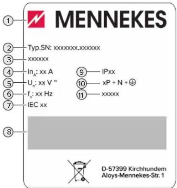
text_image
MENNEKES Typ.SN: xxxxxxxx.xxxxxxx xxxxxx In_A: xx A U_n: xx V^n f_n: xx Hz IEC xx IPxx xP + N + + xxxxx D-57399 Kirchhundem Aloys-Mennekes-Str. 1Fig. 1: Product rating plate (sample)
1 Manufacturer
2 Type number / serial number
3 Type designation
4 Rated current
5 Rated voltage
6 Rated frequency
7 Standard
8 Barcode
9 Protection class
10 Number of poles
11 Use
3.3 Delivery contents
Product
■ Quick Guide for the user
■ Quick Guide for the qualified electrician
■ Front cover * and tool for detaching the front cover
■ 5 x RFID cards (4 x user and 1 x master card; when delivered, the RFID cards have already been taught into the local whitelist)
■ Pouch with fixing elements (screws, dowels, sealing plugs), membrane glands, plug connectors, cable ties and spacers (for products with charging socket only)
■ Sticker with charging point marking according to EN 17186
■ Additional documents:
■ Drilling template (printed and perforated on cardboard box insert)
■ Circuit diagram
■ Test certificate
* Some custom products are supplied without a front cover. In this case, the front cover needs to be purchased separately from MENNEKES. The front cover is available from MENNEKES in various colours.
3.4 Product structure
Exterior view
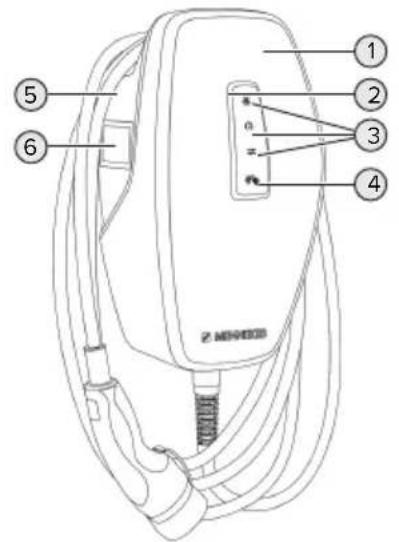
text_image
① ② ③ ④ ⑤ ⑥ Z-NEEEDFig. 2: Exterior view (example)
1 Top section of housing with front cover
2 LED status display
3 Button
■ "Solar charging"
■ "Fast charging"
■ "Customised charging"
4 RFID card reader
5 Bottom section of housing
6 Energy meter *
* Only valid for the product variants AMTRON® 4You 560.
Interior view
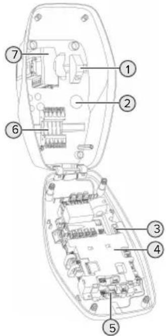
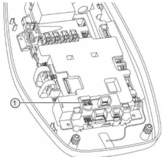
text_image
Technical diagram of an electronic device with numbered components for identificationFig. 3: Interior view (example)
1 RJ45 module
2 Cable glands *
3 Terminals (3, 4) for connecting an external switching contact (downgrade input)
4 MCU (MENNEKES Control Unit)
5 Terminals for connecting an external shunt release
6 Power supply terminals
7 Energy meter **
* Additional cable glands are located on the top and bottom.
** Only valid for the product variants AMTRON® 4You 560.
3.5 Charging modes
| Charging mode Button | |
| “Solar charging” | |
| “Fast charging” | 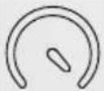 |
| "Customised charging" |
"Solar charging" mode
The charging power is dependent on the excess energy from the photovoltaic system. Charging takes place using solar energy only. The charging process starts if there is a sufficient amount of energy available to charge the vehicle at 6 A per phase.
"Fast charging" mode
Charging occurs at maximum power.
Charging mode "Customised charging"
This charging mode can be customised. Charging scenarios can be defined in the AMTRON® 4Drivers app. The selected charging scenario is carried out when the "Customised charging" button is pressed (e.g. "Solar-assisted charging", charging starts at a set time interval or with a set energy level).
Example: "Solar-assisted charging": Regardless of how much energy the photovoltaic system is producing at any given time, the vehicle is always supplied with minimum charging power (if necessary through mains power). If there is more surplus energy from the photovoltaic system, this is also made available to the vehicle. The minimum charging power can be set in the AMTRON® 4 installers app or via the web interface (qualified electrician required).

Detailed information on the "Solar charging" and "Customised charging" modes can be found in the following chapter:
“6.8.4 "Solar charging" and "Customised charging" modes” [30]
3.6 LED status display
The LED status display indicates the operating status (standby, charging, fault) of the product.
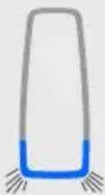
Standby
| LED beha- viour (default colour set- ting) | Meaning |
 | The product is ready for use. No vehicle is connected to the product. |
| LED lights up blue. | |
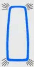 | No vehicle is connected to the product. The authorisation pro- cess is complete (validity period is configurable). |
| LED flashes blue. | |
 | A vehicle is connected to the product. Authorisation has not oc- curred. |
LED flashes blue.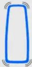 | A vehicle is connected to the product. The authorisation pro- cess is complete.Charging process paused. Pos- sible reasons are, for example:■ There is not enough energy to charge in the "Solar charging" or "Customised charging" modes.■ Blackout protection has been temporarily activated.■ The limit value for unbalanced load was exceeded temporar- ily.■ The downgrade input charging current is configured to 0 A and is active.■ A command has been received from the energy management system (power setting 0 A). |
| LED pulsates blue. | |
 | The product is ready for use. The charging station is reserved for predefined RFID cards via a con- nected backend system. |
| LED pulsates blue. |
The colour blue is preset for the "Standby" operating mode (default colour setting). The colour can be changed to green in the AMTRON® 4 installers app or web interface.
Sleep mode for reduced standby consumption: When in the "Standby" operating mode, the product can switch to sleep mode. The LED status indicator does not light up when in sleep mode. The sleep mode switches off when presence is detected or
after an interaction with the product (e.g. a charging cable is plugged in, authorisation). A qualified electrician can configure the sleep mode in the AMTRON® 4 installers app or the web interface which is enabled when in the delivery state.
Charging
| LED beha- viour (default colour set- ting) | Meaning |
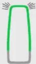
 | The vehicle is charging. |
| LED lights up green. | |
 | All requirements for charging a vehicle are met. The charging pro- cess is paused due to vehicle feedback or was terminated by the vehicle. |
| LED pulsates green. | |
 | ■ The operating temperature of the product is too high: ■ The vehicle is charged with reduced charging power. ■ Charging process tempor- arily paused. |
| LED flashes green. | ■ Communication with the con- nected energy management system or energy meter was in- interrupted. The vehicle is being charged with the configured fallback current (≥ 6 A). |
The colour green is preset in the "Charging" operating mode (default colour setting). The colour can be changed to blue in the AMTRON® 4 installers app or web interface.
Fault
| LED behaviour | Meaning |
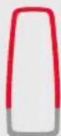 | ■ There is a fault that is preventing the vehicle from charging. The fault can only be rectified by a qualified electrician.■ The charging station was deactivated by a backend system. |
| LED lights up red. | |
 | There is a fault that is preventing the vehicle from charging (e.g. fault during charging process). |
| LED flashes red. |
For more information, see chapter Troubleshooting.
3.7 Charging connections
The product variants are available with the following charging connections:
Permanently connected charging cable with type 2 charging connector
This can be used to charge all vehicles with a type 2 charging plug. A separate charging cable is not necessary.
Type 2 charging socket with shutter for use with separate charging cable
The shutter provides additional protection against electric shock and is legally prescribed in some countries.
“2.2 Intended use” [▶ 3]
This can be used to charge all vehicles with a type 2 or type 1 charging plug (depending on the charging cable used).
All charging cables from MENNEKES can be found on our website under "Portfolio" > "Charging Cables".
“1.1 Website” [▶ 2]
4 Technical data
| AMTRON® 4You 500 11 AMTRON® | 4You 500 22 | |
| Max. charging power [kW] 11 22 | ||
| Rated current I_nA [A] 16 32 | ||
| Rated current of a charging point Mode 3 I_nC [A] | 16 32 | |
| Max. back-up fuse [A] 16 32 | ||
| Conditional rated short-circuit current I_cc [kA] | 1.1 1.8 |
| AMTRON® 4You 500 11, AMTRON® 4You 500 22 | |
| Connection single phase / three phase | |
| Nominal voltage UN[V] AC ±10 % 230 / 400 | |
| Nominal frequency fN [Hz] 50 | |
| Nominal insulation voltage Ui[V] 500 | |
| Nominal impulse withstand voltage Uimp[kV] 4 | |
| Nominal diversity factor RDF 1 | |
| Types of system earthing TN / TT (IT under certain conditions) | |
| EMC classification A+B | |
| Protection class I | |
| IP rating | IP 54 |
| Overvoltage category | III |
| Mechanical impact protection | IK10 |
| Contamination rating | 3 |
| Installation | Outdoor or indoor |
| Stationary / movable | Stationary |
| Use (according to IEC 61439-7) | AEVCS |
| External design | Wall mounted |
| Dimensions H x W x D [mm] | Product with charging cable: 402 x 226 x 168; product with charging socket: 402 x 226 x 198 |
| Weight [kg] | Product with charging cable: 4.9 - 6.9; product with charging socket: 3.4 - 3.9 |
| Standard | IEC 61851, IEC 61439-7 |
The specific standards according to which the product was tested can be found in the declaration of conformity for the product. The declaration of conformity can be found on our website in the download section for the selected product.
This product contains an energy efficiency class D light source.
| Supply line terminal strip | |||
| Number of terminals 5 | |||
| Conductor material Copper | |||
| Min. Max. | |||
| Clamping range [mm2] rigid 1.5 10 | |||
| flexible -- | |||
| with ferrule 1.5 6 | |||
| Tightening torque [Nm] -- | |||
| Downgrade input terminals | |||
| Number of terminals 2 | |||
| Specification of the external switching contact Potential-free (NC or NO) | |||
| Min. Max. | |||
| Clamping range [mm2] rigid 0.2 4 | |||
| flexible 0.2 2.5 | |||
| with ferrules 0.25 2.5 | |||
| Tightening torque [Nm] 0.5 0.5 | |||
| Switching output for shunt release terminals | ||
| Number of terminals 2 | ||
| Max. switching voltage [V] AC 230 | ||
| Max. switching voltage [V] DC 24 | ||
| Max. switching current [A] 1 | ||
| Min. Max. | ||
| Clamping range [mm2] rigid 0.2 4 | ||
| flexible 0.2 2.5 | ||
| with ferrules 0.25 2.5 | ||
| Tightening torque [Nm] 0.5 0.5 | ||
| Wireless network | Frequency band [MHz] | Maximum magnetic field strength (quasi-peak) [dBμA/m] |
| RFID (ISO / IEC 14443 A / B) | 13.56 | -16 |
| Wireless network | Max. transmission capacity [dBm] |
| WLAN 2.4 GHz | 19.75 |
5 Installation
5.1 Select location
Requirement(s):
√ Technical data and mains data are the same.
“4 Technical data” [▶ 12]
√ Permissible ambient conditions are observed.
√ The product and the charging station are in sufficient proximity to each other, depending on the length of the charging cable used.
√ The following minimum clearances to other objects (e.g. walls) must be complied with:
■ Distance to left and right: 300 mm
■ Distance above: 300 mm
5.1.1 Permissible ambient conditions
DANGER
Risk of explosion and fire
If the product is operated in potentially explosive areas (ex areas), explosive substances may be ignited by sparking of product components. There is a risk of explosion and fire.
▶ Do not use the product in potentially explosive atmospheres (e.g. gas filling stations).
ATTENTION
Material damage due to unsuitable ambient conditions
Unsuitable ambient conditions can damage the product.
▶ Protect the product from a direct water jet.
▶ Avoid direct sunlight.
▶ Ensure adequate ventilation of the product. Adhere to minimum distances.
▶ Keep the product away from heat sources.
▶ Avoid large temperature fluctuations.
| Permissible ambient conditions | |
| Min. Max. | |
| Ambient temperature [°C] -30 +50 | |
| Permissible ambient conditions | ||
| Min. Max. | ||
| Average temperature over 24 hours [°C] | +35 | |
| Altitude [m above sea level] 2,000 | ||
| Relative humidity (non-condensing) [%] | 95 | |
5.2 Preparatory work on site
5.2.1 Upstream electrical installation

The tasks described in this section may only be carried out by a qualified electrician.
! DANGER
Fire hazard due to overload
If the upstream electrical installation is flawed (e.g. supply line), there is a fire hazard.
▶ Design the upstream electrical installation according to the applicable regulatory standards and the technical data and configuration of the product.
“4 Technical data” [▶ 12]
![Mennekes AMTRON 4You 560 11 - “4 Technical data” [▶ 12] - 1](/content/2026/04/731143/images/5faa72d16d236fd427ab626d2ef899c230cbbcec8fabfb1152421db99db1f811.jpg)
When configuring the supply line (cross section and cable type), give due consideration to the following local conditions, among others:
■ Type of installation
Cable length
■ Clustering of cables
Route the supply line and the control / data cable, if applicable, to the desired location.
Installation options
On a wall
■ On the pedestal from MENNEKES
Wall mounting:
The supply line must be positioned using the drilling template provided or the figure “Drilling dimensions [mm]”.
“5.6 Installing the product on the wall” [▶ 16]
Pedestal mounting:
This is available from MENNEKES as an accessory.
See installation manual for the pedestal
5.2.2 Protective devices

The tasks described in this section may only be carried out by a qualified electrician.
The following conditions must be met when installing the protective devices in the upstream electrical installation:
Residual current device

■ National regulations must be observed (e.g. IEC 60364-7-722 (in Germany DIN VDE 0100-722)).
A differential current sensor for DC residual current monitoring > 6 mA in accordance with IEC 62752 is integrated in the product.
The product must be protected by a residual current device. As a minimum, a type A residual current device must be used.
■ No other circuits may be connected to the residual current device.
Supply line fuse (e.g. miniature circuit breaker, NH fuse)
i
■ National regulations must be observed (e.g. IEC 60364-7-722 (in Germany DIN VDE 0100-722)).
The fuse for the supply line must be designed for the product, taking account, among other considerations, of the rating plate, the required charging power and the supply line (line length, cable cross-section, number of outer conductors, selectivity).
■ The following applies for AMTRON® 4You 500 11: The rated current of the fuse for the supply line must not exceed 16 A (with C characteristics).
■ The following applies for AMTRON® 4You 500 22: The rated current of the fuse for the supply line must not exceed 32 A (with C characteristics).
Shunt release
▶ Check whether a shunt release is legally prescribed in the country of use.
“2.2 Intended use” [▶ 3]
i
■ The shunt release must be positioned next to the line circuit breaker.
■ The shunt release and the line circuit breaker must be compatible with each other.
5.3 Transporting the product
ATTENTION
Material damage due to improper transportation
Collisions and impacts may damage the product.
▶ Avoid collisions and impacts.
▶ Transport the product to the place of installation in the packed condition.
▶ Set the product down on a soft base.
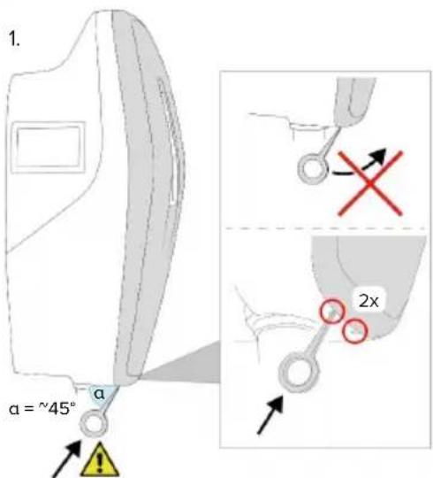
5.4 Detach front cover
In the delivery state, the front cover is not attached.

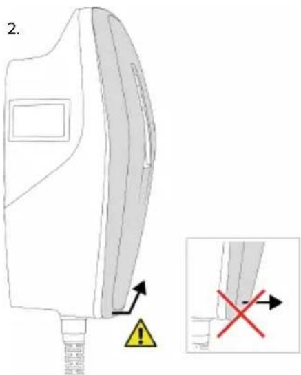
ATTENTION
Property damage due to incorrect handling
The front cover may break if it is not detached as described below. This would render the front cover unusable and it would need to be replaced.
▶ To detach the front cover, only use the tool provided in the scope of delivery.
Carefully follow the steps in the illustrations below when detaching the front cover.
text_image
1. α = ~45° α 2xFig. 4: Detach front cover - 1

text_image
2.Fig. 5: Detach front cover - 2
▶ Detach the front cover using the tool (included in the scope of delivery).
5.5 Opening the product

The tasks described in this section may only be carried out by a qualified electrician.
natural_image
Line drawing of a device with cable and connector components, no text or symbols presentFig. 6: Open product (example)
When delivered, the top section of the housing is not attached with screws. The screws are included in the scope of delivery.
▶ Detach front cover, if necessary.
“5.4 Detach front cover” [▶ 16]
▶ Unscrew screws, if necessary.
▶ Flip down the top section of the housing.
5.6 Installing the product on the wall
5.6.1 Creating drill holes

ATTENTION
Material damage due to uneven surface
Installing on an uneven surface can cause the housing to go out of shape, so that the protection class is no longer guaranteed. Consequential damage of electronic components can occur.
▶ Only install the product on an even surface.
If necessary, level out uneven surfaces with suitable measures.

MENNEKES recommends installing at an ergonomically sensible height depending on the height of the body.

ATTENTION
Material damage due to drilling dust
Consequential damage of electronic components can occur if drilling dust gets into the product.
▶ Make sure that drilling dust does not get into the product.
Do not use the product as a drilling template and do not drill through the product.
Product variants with charging cable
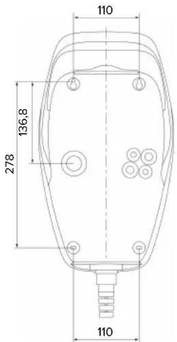
text_image
110 278 136,8 110Fig. 7: Drilling dimensions [mm]
Product variants with charging socket
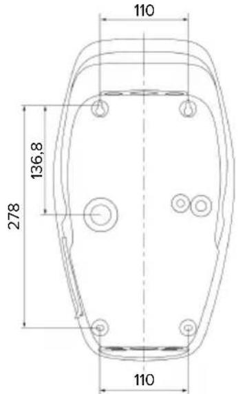
text_image
110 136,8 278 110EN
Fig. 8: Drilling dimensions [mm]
▶ Detach the perforated drilling template from the cardboard box.
▶ Use the drilling template to horizontally align, mark, and establish the drill holes ( 6 mm).
▶ Prepare the desired cable entry point.
“5.6.2 Prepare the cable entry point” [▶ 17]
▶ Install the product.
“5.6.3 Installing the product” [▶ 18]
5.6.2 Prepare the cable entry point
The following cable entry point options exist:
■ Product variants with charging cable
■ Top (2 x M20, 1 x M32)
■ Bottom (2 x M16, 2 x M20, 1 x M32)
■ Rear (2 x M16, 2 x M20, 1 x M32)
■ Product variants with charging socket
■ Top (2 x M20, 1 x M32)
■ Bottom (2 x M16, 2 x M20, 1 x M32)
■ Rear (1 x M16, 1 x M20, 1 x M32)
▶ Using a suitable tool, break out the required cable entry point at the predetermined location.
▶ Insert the matching membrane gland (included in the scope of delivery) into the relevant cable entry point.
| Cable entry point | Diameter | Matching membrane gland |
| Top side and bot-tom side | M16 or M20 | Membrane gland with strain relief.Sealing ranges:■ M16: 4.5 - 10 mm■ M20: 6 - 13 mm |
| Top side and bot-tom side | M32 Cable | gland and locknut■ Cable gland tightening torque: 7 Nm■ Locknut tightening torque: 7.5 Nm■ Sealing range: 13 - 21 mm |
| Rear side | M16, M20 or M32 | Membrane gland without strain relief.Sealing ranges:■ M16: 1 - 9 mm■ M20: 1 - 15 mm■ M32: 1 - 25 mm |
5.6.3 Installing the product

The fastening materials provided (screws and dowels) are only suitable for installation on concrete, brick or wooden walls.
Product variants with charging cable
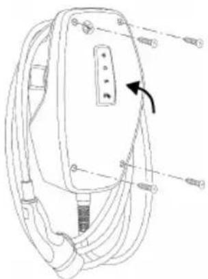
▶ Select suitable fasteners.
▶ Fasten the two upper screws in the wall to a depth of 10 mm.
▶ Hook the product onto the screws.
▶ Fasten the product to the wall using the two lower screws. Select the tightening torque according to the building material of the wall.
▶ Tighten the two upper screws. Select the tightening torque according to the building material of the wall.
▶ Check that the product is horizontally aligned and securely fastened.
▶ Insert the supply line into the product through the respective cable entry point together with the control / data line (if applicable).
Product variants with charging socket
▶ Select suitable fasteners.
▶ Fasten the two upper screws in the wall to a depth of 20 mm.
If necessary, attach the spacers (included in the scope of delivery) to the mounting holes at the rear of the product. The spacers increase the distance from the wall, making it easier to plug in the charging cable.
▶ Hook the product onto the screws.
▶ Fasten the product to the wall using the two lower screws. Select the tightening torque according to the building material of the wall.
▶ Tighten the two upper screws. Select the tightening torque according to the building material of the wall.
▶ Check that the product is horizontally aligned and securely fastened.
▶ Insert the supply line into the product through the respective cable entry point together with the control / data line (if applicable).

Approx. 30 cm of cable is required for the supply line inside the product.
Sealing plugs
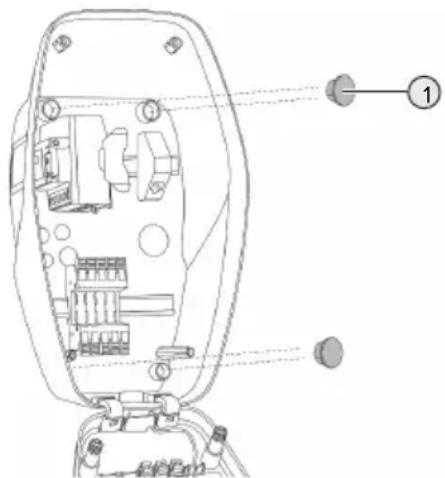
text_image
Technical diagram of a device interior with labeled components and numbered annotationFig. 9: Sealing plugs (example)
▶ Cover the fastening screws with the 4 sealing plugs (1) (included in the scope of delivery).

ATTENTION
Material damage due to missing sealing plugs
If the fastening screws are not covered, or are not adequately covered with the sealing plugs provided, the specified protection class and IP rating are no longer guaranteed. This can lead to consequential damage of electronic components.
▶ Cover fastening screws with the sealing plugs.
5.7 Electrical connection

The tasks described in this section may only be carried out by a qualified electrician.
5.7.1 Network configurations
The product can be connected in a TN / TT network.
The product can only be connected in an IT network under the following conditions:
√ Connection to a 230 / 400 V IT network is not permitted.
√ Connection to an IT network with 230 V external line voltage over a residual current circuit breaker is permissible, provided that the maximum contact voltage does not exceed 50 V AC when the first error occurs.
5.7.2 Power supply
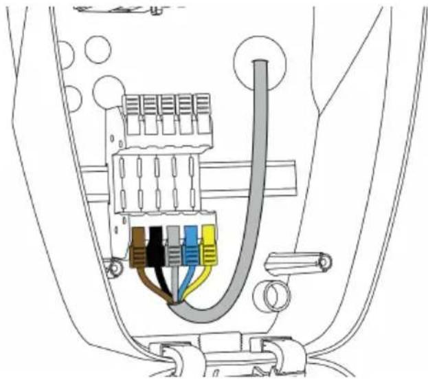
natural_image
Technical diagram of a car air intake system showing plug, valve, and wiring (no text or labels)EN
Fig. 10: Power supply connection (example)
▶ Strip the supply line insulation.
▶ Strip 12 mm of the conductor insulation.

When routing the supply line, comply with the permissible bending radius.
Single-phase operation
Connect the conductors of the supply line to the terminals L1 (brown), N (blue) and PE (yellow-green) according to the colour scheme.
▶ Comply with the connection data for the terminal strip.
“4 Technical data” [▶ 12]
▶ Check the conductors for firm contact.
Configuration is carried out in the AMTRON® 4 installers app or via the web interface.
Three-phase operation
Connect the conductors of the supply line to the terminals L1 (brown), L2 (black), L3 (grey), N (blue) and PE (yellow-green) according to the colour scheme. A clockwise rotating field is required.
▶ Comply with the connection data for the terminal strip.
“4 Technical data” [▶ 12]
▶ Check the conductors for firm contact.
Connecting the power supply in the "Solar charging" and "Customised charging" modes

MENNEKES recommends connecting the L1 phase of the charging station to the same phase of a single-phase feeding inverter. In this way, an unbalanced load can be avoided.
5.7.3 Shunt release
Requirement(s):
√ The shunt release is installed in the upstream electrical installation.
“5.2.2 Protective devices” [▶ 15]
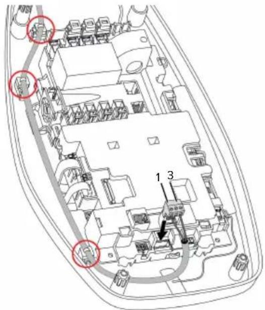
text_image
Technical diagram of a vehicle interior with numbered components and highlighted areasFig. 11: Shunt release connection
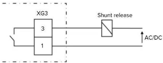
flowchart
graph LR
    A["XG3"] --> B["3"]
    A --> C["1"]
    B --> D["Shunt release"]
    C --> D
    D --> E["AC/DC"]
Fig. 12: Schematic circuit diagram: Connecting an external shunt release
▶ Strip the cable.
▶ Strip the conductors 7 mm.
▶ Connect the conductors to the plug connector (included in the scope of delivery).
▶ Insert the plug connector into XG3.
Terminal Connection (XG3)
3 Shunt release
1 Power supply
■ Max. 230 V AC or max. 24 V DC
Max. 1 A
▶ Comply with the connection data for the switching output.
“4 Technical data” [▶ 12]
Route the line as shown in the illustration above and secure it to the marked components using cable ties (included in the scope of delivery).

In the event of a fault (welded load contact), the shunt release is activated and the product is disconnected from the mains.
5.8 Surge protection equipment

The tasks described in this section may only be carried out by a qualified electrician.
The product must only be operated in accordance with all international and national regulations relating to surge protection for electrical systems. Observe the following international regulations or the respective national transposition:
IEC 62305-1 to -4
In Germany: DIN VDE 0100-443
In Germany: DIN VDE 0100-534
The product can be fitted with type 2 surge protection (available as an accessory).
See surge protection manual.
6 Commissioning
6.1 Switching on the product

The tasks described in this section may only be carried out by a qualified electrician.
Requirement(s):
√ Product is installed correctly.
√ Product is not damaged.
√ The necessary protective devices are installed in the upstream electrical installation in compliance with the relevant national regulations.
“5.2.2 Protective devices” [▶ 15]
√ During the initial setting-up process, the product was inspected in accordance with IEC 60364-6 and the applicable national regulations (e.g. in Germany: DIN VDE 0100-600).
“6.9 Testing the product” [▶ 35]
▶ Switch on the power supply and check.
6.2 Checking the mains supply

The tasks described in this section may only be carried out by a qualified electrician.
Options:
- Check the power supply using suitable measuring equipment.
The product measures the voltages of the 3 phases (L1, L2, L3). These can be read in the AMTRON® 4 installers app or via the "Status" menu in the web interface. If undervoltage or overvoltage monitoring is activated, a fault message is issued if the set thresholds are exceeded or not reached.
Example of an incorrect connection to the power supply:
■ The product is connected in the anti-clockwise rotating field. A clockwise rotating field is required.
6.3 Establishing a network connection for initial start-up
A terminal device (smartphone, tablet, laptop) and a network connection to the product are required for start-up.
EN
The product provides an access point that allows a terminal to connect to the product via WLAN. The information required to connect to the access point is in the access information insert.
▶ Activate the access point on the product by pressing the "Solar charging" and "Customised charging" buttons simultaneously for at least 2 seconds.
If the activation is successful, the LED status display flashes green once and a beep is emitted.
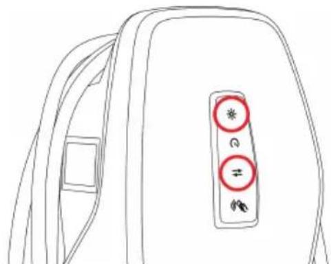
text_image
Line drawing of a backpack with three circular buttons labeled with symbols (*, #, ≠) and directional arrowsFig. 13: Activate access point (example)
▶ Activate WLAN on the terminal device.
▶ Connect the terminal device to the access point by scanning the QR code on the access information insert.
Alternatively, the terminal device and product can be connected using the terminal device's WLAN search function. The name of the access point is made up as follows "AMTRON
Alternative options
If it is not possible to connect to the network via the access point, the following alternative options are available:
■ Via the local network
“6.5 Integrating the product into a local network” [▶ 23]
■ Via a direct Ethernet connection

The tasks described below may only be carried out by a qualified electrician.
The required Ethernet port (1) on the control unit is already assigned when it is delivered. The internal Ethernet cable must be disconnected first.
text_image
Technical diagram of a vehicle interior with labeled components and numbered annotationFig. 14: Ethernet port
▶ Disconnect the internal Ethernet cable.
▶ Connect the terminal device and the product using an Ethernet cable.
Adjust the following network settings on the terminal device:
■ IPv4 address: 192.168.150.21
■ IPv4 subnet mask: 255.255.255.0
■ Default gateway: 192.168.150.1
After the initial start-up, reconnect the internal Ethernet cable.
6.4 Establishing a connection with the AMTRON® 4 installers app for configuration
The AMTRON® 4 installers app can be used to configure the product. The app can be downloaded from the Apple App Store or the Google Play Store.
Apple App Store:

https://mennek.es/s/amtron-4installers-app-ios
Google Play Store:

https://mennek.es/s/amtron-4installers-app-android
Requirement:
√ Terminal device and product must be on the same network.
“6.3 Establishing a network connection for initial start-up” [▶ 21]
▶ Download and open the app.
▶ Run a network scan in the app to find the product on the network.
▶ Select the product.
Alternative option
If using the app is not desired, the product can alternatively be configured via the web interface.
Requirement:
√ Terminal device and product must be on the same network.
“6.3 Establishing a network connection for initial start-up” [▶ 21]
▶ Open the current web browser.
The web interface can be reached via http://IP address.
i
If the terminal device is connected to the product via the access point, the IP address of the product is: 192.168.170.10
If the terminal device is connected to the product via the direct Ethernet connection, the IP address of the product is: 192.168.150.10
If the terminal device is integrated in the local network, the IP address is assigned dynamically. The IP address can be read out via the router or a network scan, for example.
Example:
■ IP address of the product: 192.168.150.52
■ The web interface can be reached via: http://192.168.150.52
6.4.1 User roles
There are 3 user roles for configuration, each with different setting options:
■ "Installer"
■ The configuration described in this user role may only be carried out by a qualified electrician. Settings can be made that require specialist knowledge and may result in electrical hazards if not properly configured.
This user role has permission to edit all configurable parameters.
■ "Owner"
■ This user role is intended for the charging station operator.
■ The setting options are limited (e.g. load management, network connection, backend system, LED colour scheme, presence detection).
■ "User"
■ This user role is intended for the end user.
■ No settings can be made.
Passwords for the user roles are assigned during initial start-up and can be written on the stickers if required. The stickers can be found in the access information insert and can then be affixed to the enclosed Quick Guide.
6.4.2 Set-up Wizard
The Set-up Wizard helps the user with the basic product configuration (e.g. setting the maximum charging current).
The Set-up Wizard can only be started if the user is logged in with the 'Installer' user role. The settings made in the Set-up Wizard can be changed at any time.
6.5 Integrating the product into a local network

The tasks described in this section may only be carried out by a qualified electrician.
Integration into a local network offers the following options, for example:
■ Connection to an energy meter on the same network (Modbus TCP).
■ Connection to an energy management system on the same network (Modbus TCP, EEBus or SEMP).
■ Configuration can be carried out at any time via the AMTRON® 4 installers app or the web interface.
■ Operating the product via the AMTRON® 4Drivers app.
Integration can take place via Ethernet or WLAN. When delivered, the product is configured as a DHCP client and is dynamically assigned an IP address by the router.
Ethernet
If the product is to be integrated into a network via Ethernet, the product and the router must be connected with a data cable (maximum 100 m long) (star topology). Serial switching of the data line (looping through) is not possible. An RJ45 module is pre-assembled in the product and ready for connection. The RJ45 module consists of an RJ45 socket and a top-hat rail adapter.
The RJ45 module is suitable for the following data lines:
Cat. 6A
■ Rigid or flexible conductors with a wire gauge range from 22 to 26 AWG
■ Sheath diameter: 6 to 8.5 mm
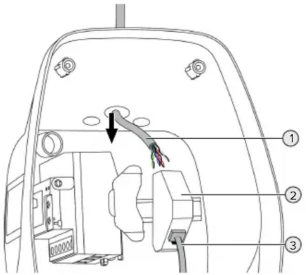
text_image
Technical diagram of a vehicle's rear compartment with labeled parts and directional arrows indicating movement or force.Fig. 15: Connecting the data line (example)
▶ Insert the data line (1) into the product.
▶ Disconnect the internal Ethernet cable (3).
Remove the RJ45 module (2) from the top-hat rail and open it.
▶ Connect the data line to an RJ45 socket.
See the manual for the RJ45 socket.
▶ Insert the RJ45 socket into the top-hat rail adapter and snap it into place.
▶ Fit the top-hat rail adapter on the top-hat rail.
▶ Reconnect the internal Ethernet cable (3).
Configuration is carried out in the AMTRON® 4 installers app or via the web interface.
WLAN
Configuration is carried out in the AMTRON® 4 installers app or via the web interface.
6.6 Establishing a connection with the AMTRON® 4Drivers app
The AMTRON ^® 4Drivers app allows the end user to conveniently manage the product and, for example, authorise charging processes.
The app can be downloaded from the Apple App Store or the Google Play Store. The access information for the app is in the access information insert.
Apple App Store:

https://mennek.es/s/amtron-4drivers-app-ios
Google Play Store:

https://mennek.es/s/amtron-4drivers-app-android
Requirement:
√ To use the AMTRON® 4Drivers app, the product must be permanently connected to the Internet via the local network.
√ To pair the app and the product for the first time, both devices must be on the same network.
▶ Download and open the app.
▶ Register in the app with an email address.
▶ Establish a network connection between the terminal device and the product.
▶ Run a network scan in the app to find the product.
▶ Enter the pairing code manually or by scanning the QR code (see access information insert) in the app to pair the product with the terminal device.

If charging processes are to be authorised in the AMTRON® 4Drivers app, authorisation via RFID / app must be set up. Configuration can be carried out in the AMTRON® 4Installers app or via the web interface.
6.7 Managing RFID cards
For authorisation via RFID, the RFID cards must have been taught into the local whitelist. The following options are available for managing RFID cards:
In the AMTRON® 4Drivers app
In the AMTRON® 4 installers app or web interface
■ Via the master RFID card (described below)

MENNEKES recommends teaching the user RFID cards into the AMTRON® 4Drivers app. If this is done in the AMTRON® 4Installers app, web interface or via the master RFID card, then the user RFID cards will not be visible in the AMTRON® 4Drivers app.
Adding or removing RFID card(s) to/from the whitelist
The master RFID card can be used to add or remove new RFID cards to or from the internal whitelist.
▶ Hold the master RFID card in front of the RFID card reader to activate Teach mode for 1 minute.
⇒ The bottom LED on the LED status display will rapidly flash blue.
▶ Hold the RFID card that you want to add or remove in front of the RFID card reader.
If the RFID card has not yet been added to the whitelist, it will be added to the whitelist as a user RFID card. The bottom LED on the LED
status display will light up green for 1 second. An ascending sequence of notes will then sound.
If the RFID card has already been added to the whitelist, it will be removed from the whitelist. The top LED on the LED status display will light up red for 1 second. A descending sequence of notes will sound.
Teaching in a master RFID card
Configuration is carried out in the AMTRON® 4Installers app or via the web interface.
6.8 Use cases
6.8.1 Downgrade

The tasks described in this section may only be carried out by a qualified electrician.
If the maximum mains supply current is not available under certain circumstances or at certain times, the charging current can be reduced by using the downgrade input. For example, the downgrade input can be controlled by the following criteria or control systems:
Electricity rate
Time
Load shedding
■ Manual control
■ External load management
When delivered, the downgrade input is controlled as follows:
| Switching contact status | Downgrade status |
| open Downgrade inactive | |
| closed Downgrade active | |
The logic of the downgrade input can be changed in the AMTRON® 4 installers app or via the web interface.
Electrical connection of the switching contact

ATTENTION
Material damage due to improper installation
Improper installation of the switching contact can damage the product or lead to malfunctions. Observe the following requirements during the installation:
▶ Select suitable cable routing to avoid interference.
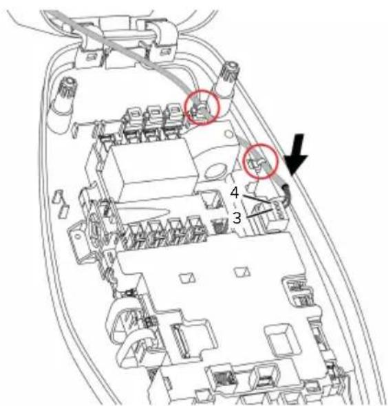
text_image
Technical diagram of an electronic device with numbered components and highlighted areasFig. 16: Downgrade input connection
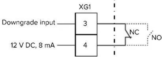
text_image
XG1 Downgrade input 3 NC NO 12 V DC, 8 mA 4Fig. 17: Schematic circuit diagram: Connection of an external switching contact (default setting: NO)
▶ Install the external switching contact.
▶ Strip the cable.
▶ Strip the conductors 7 mm.
▶ Connect the conductors to the plug connector (supplied).
▶ Insert the plug connector into XG1.
▶ Note the connection data for the downgrade input.
“4 Technical data” [▶ 12]
Route the cable as shown in the illustration above and secure it to the marked components using cable ties (supplied).
Configuration is carried out in the AMTRON® 4 installers app or via the web interface.
6.8.1.1 Downgrade when using a Siemens PAC2200 7KM energy meter
Requirement(s):
■ Firmware Version 1.1 or higher must be installed.
■ The external Siemens PAC2200 7KM energy meter must have been integrated in the network and configured.
“6.8.2 Connecting an external energy meter” [▶ 27]

The downgrade input of the energy meter and the downgrade input of the charging station cannot be used at the same time.
The digital input of the energy meter can be used as a downgrade input to reduce the current for a single charging point or a charging point network. There are two options for controlling the digital input:
■ Via an external 12 V DC or 24 V DC control signal
■ Via a coupling relay and an additional power supply
When delivered, the downgrade input is controlled as follows:
| Switching contact status | Downgrade status |
| open Downgrade inactive | |
| closed Downgrade active | |
The logic of the downgrade input can be changed in the AMTRON® 4 installers app or via the web interface.
Control via an external 12 V DC or 24 V DC control signal (when in delivery state)
The control signal can be generated by an external load shedding relay or an external timer, for example. As soon as the 12 V DC or 24 V DC control signal is applied to the digital input, the charging current is reduced according to the set configuration.
▶ Connect the external control system to terminal 12 of the digital input.
Control via a coupling relay and additional power supply (when in delivery state)
The digital input can be controlled with a coupling relay (S0) and an additional power supply (1).
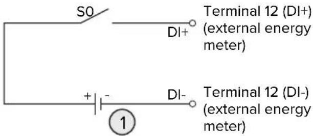
text_image
S0 DI+ Terminal 12 (DI+) (external energy meter) + - DI- Terminal 12 (DI-) (external energy meter) ①Fig. 18: Control via a coupling relay and additional power supply (when in delivery state)
1 External power supply, max. 30 V DC
▶ Connect the external control system to terminal 12 of the digital input.
Configuration is carried out in the AMTRON® 4 installers app or via the web interface.
6.8.2 Connecting an external energy meter

The tasks described in this section may only be carried out by a qualified electrician.
The connection to an external energy meter offers the following options, for example:
■ Blackout protection
■ Solar charging

Information on compatible energy meters can be found on our website: https://www.mennekes.org/emobility/knowledge/compatible-meters/

▶ Install the external energy meter in the upstream electrical installation.
“6.8.2.1 Structure” [▶ 29]
▶ Integrate the energy meter and the product on the same network.
“6.5 Integrating the product into a local network” [▶ 23]
Configuration is carried out in the AMTRON ^® 4 installers app or via the web interface.
Configuring the energy meter
To connect the energy meter to the product, settings may need to be made in the energy meter. Instructions for connecting selected energy meters can be found on the above website.
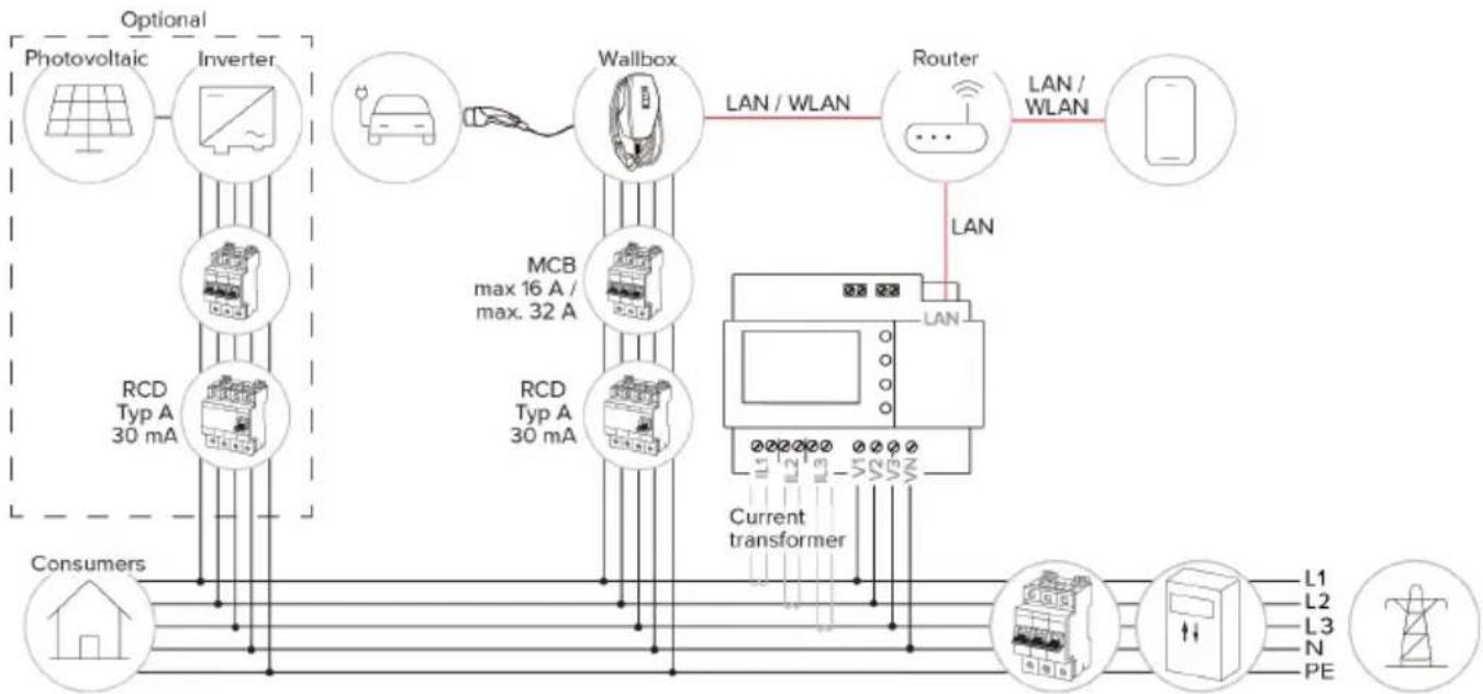
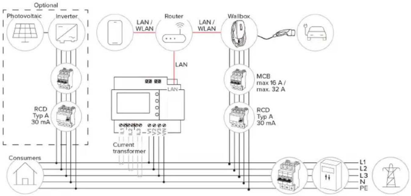
6.8.2.1 Structure
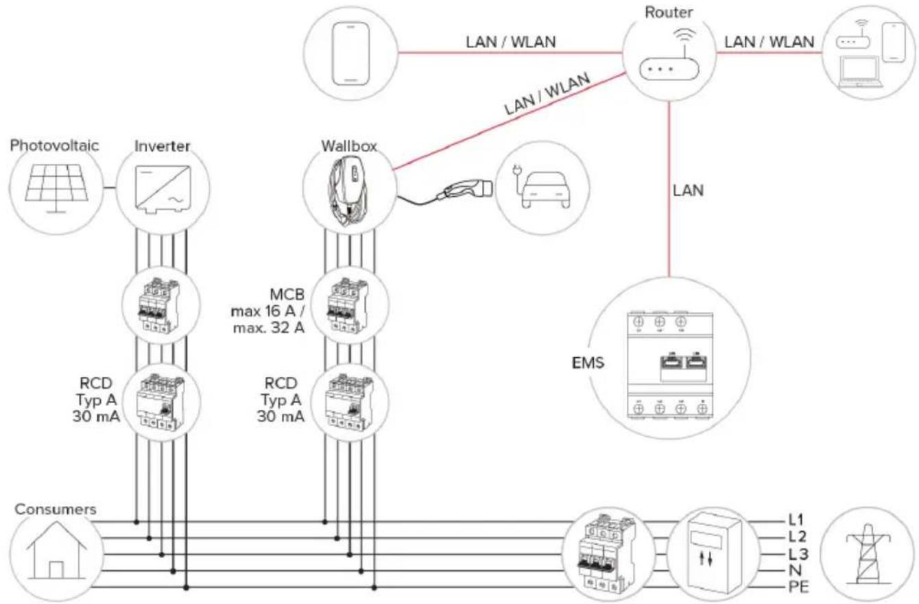
The external energy meter can be placed to measure only the external loads or to measure the total consumption (external loads and charging station). The following figures show the configuration structure for using the MENNEKES accessory set 18662 (Siemens PAC2200 7KM including current transformer).
EN
Energy meter measures total consumption (default setting)
flowchart
graph TD
    A["Photovoltaic"] --> B["Inverter"]
    B --> C["Wallbox"]
    C --> D["Router"]
    D --> E["Smartphone"]
    F["RCD Typ A 30 mA"] --> C
    G["Consumers"] --> H["Current transformer"]
    I["L1 L2 L3 N PE"] --> J["Power Supply"]
    K["Max 16 A / max. 32 A"] --> C
    L["LAN / WLAN"] --> C
    M["LAN"] --> D
    N["Current transformer"] --> C
    O["Consumers"] --> P["Power Supply"]
    Q["Consumers"] --> R["Power Supply"]
Energy meter measures external consumers only
flowchart
graph TD
    A["Photovoltaic"] --> B["Inverter"]
    B --> C["RCD Typ A 30 mA"]
    C --> D["Consumers"]
    D --> E["Current transformer"]
    E --> F["L1 L2 L3 N PE"]
    F --> G["Wallbox"]
    G --> H["MCB max 16 A / max. 32 A"]
    H --> I["Router"]
    I --> J["LAN / WLAN"]
    J --> K["LAN"]
    K --> L["LAN / WLAN"]
    L --> M["RS/DC Controller"]
    M --> N["PE"]
    style A fill:#f9f,stroke:#333
    style B fill:#ccf,stroke:#333
    style C fill:#cfc,stroke:#333
    style D fill:#fcc,stroke:#333
    style E fill:#cff,stroke:#333
    style F fill:#ffc,stroke:#333
    style G fill:#fcc,stroke:#333
    style H fill:#ffc,stroke:#333
    style I fill:#fcc,stroke:#333
    style J fill:#cff,stroke:#333
    style K fill:#ffc,stroke:#333
    style L fill:#fcc,stroke:#333
    style M fill:#ffc,stroke:#333
    style N fill:#fcc,stroke:#333
6.8.3 Blackout protection

The tasks described in this section may only be carried out by a qualified electrician.
In order to avoid overloading the building connection with a charging point (blackout protection), it is necessary to record the current values from the building connection with an additional external energy meter. The energy meter also takes account of other consumers in the building.
▶ Connect an external energy meter.
“6.8.2 Connecting an external energy meter” [▶ 27]
Configuration is carried out in the AMTRON ^® 4 installers app or via the web interface.
6.8.4 "Solar charging" and "Customised charging" modes

The tasks described in this section may only be carried out by a qualified electrician.
▶ Connect an external energy meter.
“6.8.2 Connecting an external energy meter” [▶ 27]
| Charging mode Button | |
| “Solar charging” |  |
| "Customised charging" |  |
"Solar charging" mode
The charging power is dependent on the excess energy from the photovoltaic system. Charging takes place using solar energy only. The charging process starts if there is a sufficient amount of energy available to charge the vehicle at 6 A per phase.
Charging mode "Customised charging"
This charging mode can be customised. Charging scenarios can be defined in the AMTRON® 4Drivers app. The selected charging scenario is carried out when the "Customised charging" button is pressed (e.g. "Solar-assisted charging", charging starts at a set time interval or with a set energy level).
Example: "Solar-assisted charging": Regardless of how much energy the photovoltaic system is producing at any given time, the vehicle is always supplied with minimum charging power (if necessary through mains power). If there is more surplus energy from the photovoltaic system, this is also made available to the vehicle. The minimum charging power can be set in the AMTRON® 4 installers app or via the web interface (qualified electrician required).
Special features of the 11 kW variant
The 11 kW variant supports single-phase and three-phase solar charging processes. This allows for optimal use of both low and high performance photovoltaic systems. The charging station can also dynamically switch between single-phase and three-phase charging. Configuration is carried out in the AMTRON® 4 installers app or via the web interface. The following settings are possible for the 11 kW variant:
■ Dynamic switchover between single-phase and three-phase charging (default setting): In the "Solar charging" and "Customised charging" modes, dynamic switching between single-phase and three-phase charging takes place during charging. Charging starts at 1.4 kW of excess energy and this can be increased to a maximum of 11 kW. The duration of the charging pause between a phase switchover can be set in the AMTRON® 4 installers app or via the web interface.
■ Single-phase charging:
In the "Solar charging" and "Customised charging" modes, only single-phase charging is
used. Charging starts at 1.4 kW of excess energy and this can be increased to a maximum of 3.7 kW.
■ Three-phase charging:
In the "Solar charging" and "Customised charging" modes, only three-phase charging is used.
Charging starts at 4.2 kW of excess energy and this can be increased to a maximum of 11 kW.
i
The automatic phase change was implemented according to the CharIN method. MENNEKES cannot guarantee compatibility with all vehicles on the market. In some cases, the charging process may be interrupted, or the vehicle and/or the wallbox may be damaged.
For example, the Kia eNiro, Hyundai Kona,
Fiat 500e and Renault Zoe could be incompatible. It is not possible to maintain a comprehensive list because compatibility can vary even within a series, depending on the year of manufacture and software version of the vehicle. Please check with your vehicle manufacturer to verify whether the vehicle supports this function.
MENNEKES accepts no liability for any damage caused by incorrect use or incompatibility.
Special features of the 22 kW variant
Charging starts at 4.2 kW of excess energy. The charging power can be raised to a maximum of 22 kW. When the product is connected and configured as single-phase, the charging power is between 1.4 kW and 7.4 kW.
Configuration
Configuration is carried out in the AMTRON® 4 installers app or via the web interface.
Selecting the charging mode
The buttons can be used to select the appropriate charging mode.
| Charging mode Button | |
| “Solar charging” |  |
| “Fast charging” |  |
| "Customised charging" |  |
The active charging mode is backlit. If a charging scenario that is not stored on the button has been activated in the AMTRON® 4Drivers app for "Customised charging", the backlighting of the "Customised charging" button pulsates.
If the product is not configured for the "Solar charging" and "Customised charging" modes, the buttons have no function. The following applies to the 22 kW variants: It is possible to switch between the "Fast charging", "Solar charging" and "Customised charging" modes at any time (even during an active charge).
The following applies to the 11 kW variants with activated dynamic phase switchover:
It is possible to switch between the "Fast charging", "Solar charging" and "Customised charging" modes at any time (even during an active charge).
The following applies to the 11 kW variants with deactivated dynamic phase switchover:
It is possible to switch between the "Solar charging" and "Customised charging" modes at any time (even during an active charge).
It is not possible to switch between the "Fast charging" and "Solar charging" / "Customised charging" modes during an active charge. The vehicle must be disconnected from the charging station before switchover.
6.8.5 Energy management system

The tasks described in this section may only be carried out by a qualified electrician.
If required, the product can be connected to an energy management system via Modbus TCP, EEBus or SEMP, in order to implement complex application cases. The product is controlled by the energy management system (Master).

Information on compatible energy management systems can be found on our website: www.mennekes.org/emobility/knowledge/ compatible-systems-and-interfaces/

▶ Install the energy management system in the upstream electrical installation.
“6.8.5.1 Structure” [▶ 33]
▶ Integrate the energy management system and the product on the same network.
“6.5 Integrating the product into a local network” [▶ 23]
Configuration is carried out in the AMTRON ^® 4 installers app or via the web interface.
6.8.5.1 Structure
flowchart
graph TD
    A["Photovoltaic"] --> B["Inverter"]
    B --> C["RCD Typ A 30 mA"]
    C --> D["Consumers"]
    D --> E["Wallbox"]
    E --> F["RCD Typ A 30 mA"]
    F --> G["EMS"]
    G --> H["Router"]
    H --> I["L1 L2 L3 N PE"]
    H --> J["L1 L2 L3 N PE"]
    style A fill:#f9f,stroke:#333
    style B fill:#ccf,stroke:#333
    style C fill:#cfc,stroke:#333
    style D fill:#fcc,stroke:#333
    style E fill:#cff,stroke:#333
    style F fill:#ffc,stroke:#333
    style G fill:#cfc,stroke:#333
    style H fill:#fcc,stroke:#333
    style I fill:#fff,stroke:#333
    style J fill:#fff,stroke:#333
EN
6.8.5.2 Connection via SEMP
From firmware version 1.3 onwards, the charging station can be connected to an energy management system (e.g. the "Sunny Home Manager" from SMA) via SEMP.
The SEMP charging modes can be controlled as follows using the buttons on the charging station:
| SEMP charging mode (example "Sunny Home Manager" from SMA) | Button |
| "Excess charge" |  |
| "Instant charging" |  |
| "Manual configuration" | 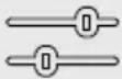 |
Please refer to the SMA documentation for an explanation of the charging modes.
Configuration:
The SEMP interface can be activated via the web interface of the charging station, where settings for the "Manual Configuration" charging mode can be configured (e.g. minimum and maximum energy requirements in kWh, planned departure time).

The firmware version 1.3 and the AMTRON® 4Drivers app version 1.0 are not yet fully compatible for connection via SEMP:
It is not possible to select the SEMP charging modes in the AMTRON® 4Drivers app.
It is not possible to adjust the settings for the "Manual configuration" charging mode in the AMTRON® 4Drivers app.
6.8.6 Connecting to a backend system
The product can be connected to a backend system via the local network. The product is operated via the backend system.
To connect via the local network, the network must have a permanent Internet connection.
“6.5 Integrating the product into a local network” [▶ 23]
Configuration is carried out in the AMTRON® 4 installers app or via the web interface.

We recommend using a secure Internet connection to communicate with the backend system. This can be done, for example, via a SIM card provided by the backend system operator or via a connection secured by TLS. In the case of access via the public Internet, at least the HTTP basic authentication should be activated, otherwise the data will be transmitted in a format that is readable for unauthorised third parties.

Information concerning OCPP and the password for the HTTP basic authentication are provided by your backend system provider.
6.8.7 Load management in charging point networks

The tasks described in this section may only be carried out by a qualified electrician.
From firmware version 1.1 and later, the load management can be operated in charging point networks (up to 100 charging points). Operating principle:
The value of the maximum upper power limit of the entire charging point network can be configured statistically or dynamically (external energy meter required).
The load management distributes the maximum available power to the connected vehicles. If less than 6 A is available for the next vehicle, the last vehicles connected have to wait to start charging until another vehicle has finished charging.
■ The load management provides each vehicle with as much charging current as the charging station is configured for.
A charging station can be configured as load management master and so takes care of the load management coordination for all charging stations in the charging point network. The charging stations can be added and the load management configured in the AMTRON® 4Installers app or in the web interface of the load management master.
If the downgrade input on the load management master is activated, the maximum upper power limit of the entire charging point network is reduced to the set value.
Requirement(s):
√ All charging stations that should be operated with load management should be in the same network.
“6.5 Integrating the product into a local network” [▶ 23]
i
■ MENNEKES recommends connecting the products in the network via Ethernet.
■ MENNEKES recommends using a router with an activated DHCP function.
The configuration of the load management in the entire charging point network can be done via the AMTRON® 4 installers app or the web interface of a preferred charging station (load management master) in the "Charging point network" menu. All products that should be taken into consideration by the load management can be selected or manually added there. The load management can then be configured afterwards.
Configuration with a router / switch with a deactivated DHCP server
If there is no DHCP server active on a router / switch in the network, or if a static IP address assignment needs to be carried out, all charging stations must be manually assigned their own individual static IP address in the same address range. This must be set individually in the AMTRON® 4 installers app or in the web interface of each charging station.
6.9 Testing the product

The tasks described in this section may only be carried out by a qualified electrician.
At initial start-up, test the product in accordance with IEC 60364-6 and the applicable national regulations (e.g. in Germany: DIN VDE 0100-600).
The test can be carried out in conjunction with the MENNEKES test box and standard-compliant test equipment. The MENNEKES test box simulates vehicle communication. Test boxes are available as an accessory from MENNEKES.
6.10 Closing the product

The tasks described in this section may only be carried out by a qualified electrician.

ATTENTION
Material damage due to crushed components or cables
Damage and malfunctions can occur due to crushed components or cables.
When closing the product ensure that components or cables are not crushed.
▶ Fix components or cables in place if necessary.
natural_image
Line drawing of a device with multiple cables and connectors, no text or symbols presentFig. 19: Close product (example)
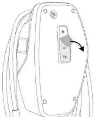
▶ Flip up the top section of the housing.
▶ Screw the top and bottom housing sections together. Tightening torque: 1.2 Nm.
Removing the protective film
In the delivery state, a protective film is applied in the area of the LED status display. MENNEKES cannot guarantee that the protective film can be removed without residue if the product has been in use for some time and has been exposed to environmental influences.
▶ Remove the protective film during commissioning.
natural_image
Line drawing of a device rear panel with a button and arrow indicator (no text or symbols)Fig. 20: Remove protective film (example)
6.11 Attaching the front cover
Some custom products are supplied without a front cover. In this case, the front cover needs to be purchased separately from MENNEKES.

ATTENTION
Property damage due to incorrect handling
The front cover may break if it is not attached as described below. This would render the front cover unusable and it would need to be replaced.
▶ Carefully follow the steps in the illustrations below when attaching the front cover.
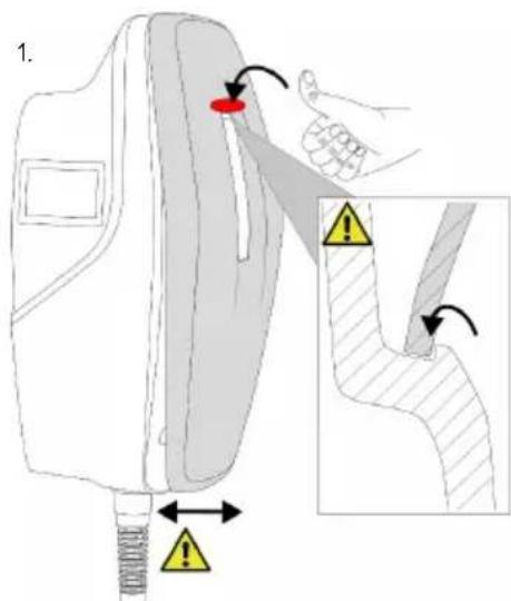
text_image
1.Fig. 21: Attach front cover - 1
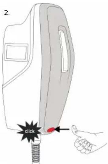
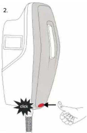
text_image
2. clickFig. 22: Attach front cover - 2
▶ Attach front cover and snap into place.
6.12 Attach charging point labelling
Charging point labelling according to EN 17186 defines a standardised system for labelling charging points for electric vehicles.
The product meets the European normative minimum requirements for charge point labelling according to EN 17186 when the charge point labelling sticker is attached to the product. Depending on the installation location (e.g. semi-public area) and the national requirements of the country of use, further information may need to be added.
The operator is responsible for affixing the charging point labelling. You can find more information on our website:
https://www.mennekes.org/emobility/knowledge/charge-point-labelling/

▶ Attach sticker to the product as required.
Product variants with charging cable
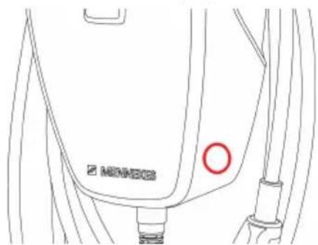
text_image
MONECO MONECOFig. 23: Suggestion for where to place the sticker
Product variants with charging socket
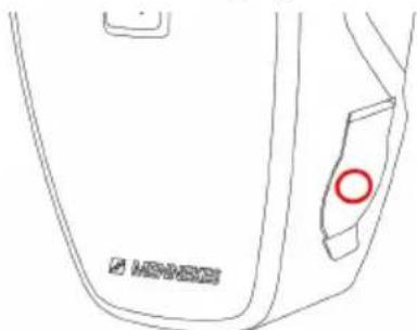
natural_image
Line drawing of a device casing with a red circle highlighting a specific part (no text or symbols present)Fig. 24: Suggestion for where to place the sticker
EN
7 Operation
7.1 AMTRON® 4Drivers app
For private use (e.g. home, apartment building), operation via the AMTRON® 4Drivers app is the most convenient option.
The app can be downloaded from the Apple App Store or the Google Play Store. The access information for the app is in the access information insert.
Apple App Store:

https://mennek.es/s/amtron-4drivers-app-ios
Google Play Store:

https://mennek.es/s/amtron-4drivers-app-android
The product can also be used without the AMTRON® 4Drivers app.
7.2 Authorisation
▶ Authorise (dependent on the configuration).
The following authorisation options are available:
No authorisation (Autostart)
All users can charge.
Authorisation via RFID
Users that have an RFID card that has been entered in the whitelist can charge their vehicle.
▶ Hold the RFID card in front of the RFID card reader.
If the RFID card is valid, the bottom LED on the LED status display will light up green for 1 second (if reader is in delivery state) and an ascending sequence of notes sounds.
If the RFID card is invalid, the top LED on the LED status display will light up red for 1 second and a descending sequence of notes sounds.
Authorisation via the AMTRON® 4Drivers app
Authorisation takes place via the AMTRON® 4Drivers app.
Authorisation through the backend system
Authorisation is dependent on the backend system, for example an RFID card, smartphone app or ad hoc (e.g. direct payment).
▶ Follow the instructions for the respective backend system.

If the vehicle is not connected to the product within the configured time, the authorisation is reset and the product switches to Standby mode. The authorisation process must be repeated. When delivered, the authorisation is reset after 1 minute.
7.3 Charging the vehicle
WARNING
Risk of injury from using unsuitable aids
If unsuitable aids (e.g. adapter plugs, extension cables) are used during the charging process, there is a risk of electric shock or cable fire.
▶ Use only the charging cable intended for the vehicle and the product.
Requirement(s):
√ The authorisation process is complete (if necessary).
√ The vehicle and the charging cable are suitable for Mode 3 charging.
▶ If necessary, remove the protective cap from the charging plug.
▶ Connect the charging cable to the vehicle.
Only valid for product variants with charging socket:
▶ Open hinged lid.
▶ Insert the charging plug completely into the charging socket on the product.
Selecting the charging mode
“3.5 Charging modes” [▶ 8]
The buttons can be used to select the appropriate charging mode.
| Charging mode Button | |
| “Solar charging” |  |
| “Fast charging” |  |
| "Customised charging" |  |
The active charging mode is backlit. If a charging scenario that is not stored on the button has been activated in the AMTRON® 4Drivers app for "Customised charging", the backlighting of the "Customised charging" button pulsates.
If the product is not configured for the "Solar charging" and "Customised charging" modes, the buttons have no function.
The following applies to the 22 kW variants: ■ It is possible to switch between the "Fast charging", "Solar charging" and "Customised charging" modes at any time (even during an active charge).
The following applies to the 11 kW variants with activated dynamic phase switchover:
It is possible to switch between the "Fast charging", "Solar charging" and "Customised charging" modes at any time (even during an active charge).
The following applies to the 11 kW variants with deactivated dynamic phase switchover:
It is possible to switch between the "Solar charging" and "Customised charging" modes at any time (even during an active charge).
It is not possible to switch between the "Fast charging" and "Solar charging" / "Customised charging" modes during an active charge. The vehicle must be disconnected from the charging station before switchover.
Charging process does not start
If the charging process does not start, the communication between the charging point and the vehicle may be faulty, for example.
▶ Check the charging plug and the charging socket for foreign objects and remove if necessary.
▶ Have the charging cable replaced by a qualified electrician if necessary.
Ending the charging process

ATTENTION
Material damage due to tensile stress
Tensile stress on the cable may cause cable breaks and other damage.
▶ Grasp the charging cable at the charging plug, and pull it out of the charging socket.
▶ End the charging process on the vehicle, in the AMTRON® 4Drivers app, or by holding the RFID card in front of the RFID card reader.
▶ Grasp the charging cable at the charging plug and pull it out of the charging socket. For product variants with charging socket: first remove the charging plug from the vehicle. Then unplug the charging plug from the product.
▶ Put the protective cap on the charging plug.
For product variants with charging cable: Hang the charging cable on the enclosure without any kinks.
It is not possible to remove the charging plug from the charging socket on the product
▶ Restart the charging process and end it again.
In exceptional cases, the charging plug may not unlock mechanically. In this case, the charging plug cannot be removed and needs to be unlocked manually.
▶ Have the charging plug unlocked manually by a qualified electrician.
“9.2 Unlocking the charging plug manually” [▶ 43]
8 Servicing
8.1 Maintenance

DANGER
Risk of electric shock due to damaged product
If a damaged product is used people can be seriously injured or killed due to an electric shock.
▶ Do not use a damaged product.
▶ Mark a damaged product to ensure that no one uses it.
▶ Arrange for a qualified electrician to rectify the damage without delay.
▶ Have the product taken out of service by a qualified electrician if necessary.
▶ Check the product for operational readiness and external damage daily and/or prior to each charging process.
Examples of damage:
■ Defective enclosure
■ Defective or missing components
■ Illegible or missing safety labels

Upon sale of the product, ownership and responsibility for it are transferred to the operator. Thus, the operator is also responsible for ensuring that maintenance work is carried out correctly and in accordance with applicable national regulations.
▶ Have the product regularly maintained by a qualified electrician. Take out a maintenance contract with a service partner if necessary.
8.1.1 Maintenance work

The tasks described in this section may only be carried out by a qualified electrician.
▶ Observe the national regulations of the country of use regarding maintenance (in Germany, for example, DGUV Regulation 3).
Select the maintenance intervals with due consideration of the following aspects:
■ Age and condition of the product
■ Environmental influences
Stress
■ Last test reports
Recommended maintenance work
MENNEKES recommends carrying out maintenance work at regular intervals. You can find a list of recommended maintenance tasks in the MENNEKES maintenance log on our website, under "Services" > "Documents for Installers".
“1.1 Website” [▶ 2]
8.2 Cleaning

DANGER
Risk of electric shock due to improper cleaning
The product contains electrical components that carry high voltage. In case of improper cleaning, people can be seriously injured or killed due to electric shock.
▶ Clean only the outside of the housing.
▶ Do not use running water.

ATTENTION
Material damage due to improper cleaning
Improper cleaning can damage the housing.
▶ Wipe the housing with a dry cloth or a cloth lightly moistened with water or spirit (94 % vol.).
▶ Do not use running water.
▶ Do not use high-pressure cleaning devices.
8.3 Firmware update

The current firmware is available on our website under "Services" > "Software updates".
“1.1 Website” [▶ 2]
The firmware version (e.g. 1.0) can be viewed and updated in the AMTRON® 4 installers app or via the "System" menu in the web interface.
During the firmware update, the top LED on the LED status display rapidly flashes red.
9 Troubleshooting
In the event of a fault, the upper LED of the LED status display lights up or flashes red. The fault must be rectified for further operation.
The upper LED of the LED status display flashes red
If the upper LED flashes red, the fault can be rectified by the user or operator. Possible faults are, for example:
■ Fault during the charging process.
■ There is an undervoltage or overvoltage (if undervoltage/overvoltage monitoring is active).
To correct the fault, observe the following sequence:
▶ End the charging process and disconnect the charging cable.
▶ Plug the charging cable back in and start the charging process.

Some faults are rectified automatically after a short wait. A qualified electrician is needed if the fault persists / recurs.
The upper LED of the LED status display lights up red
If the LED lights up red, the fault can only rectified by a qualified electrician.

The tasks described below may only be carried out by a qualified electrician.
Possible faults are, for example:
■ Self-test of the electronics failed.
■ Self-test of the DC residual current monitoring failed.
■ Welded load contact (welding detection).
To correct the fault, observe the following sequence:
▶ Disconnect the product from the power supply for 3 minutes and restart.
On our website under "Services" > "Software updates", check whether a firmware update is available and upload it if necessary.
“1.1 Website” [▶ 2]
Read the fault diagnosis in the AMTRON® 4 installers app or in the web interface and rectify the fault.

You can find a document on troubleshooting on our website under "Services" > "Documents for installers". The fault messages, possible causes and possible solutions are described there.
“1.1 Website” [▶ 2]
▶ Document the fault.
You can find the MENNEKES fault report on our website under "Services" > "Documents for installers".
“1.1 Website” [▶ 2]
9.1 Spare parts
If replacement parts are necessary for troubleshooting, these must first be checked to ensure identical design.
▶ Use only original spare parts that are provided and / or approved by MENNEKES.
See the installation manual for the spare part
9.2 Unlocking the charging plug manually

The tasks described in this section may only be carried out by a qualified electrician.
In exceptional cases, the charging plug may not unlock mechanically. In this case, the charging plug cannot be removed and needs to be unlocked manually.
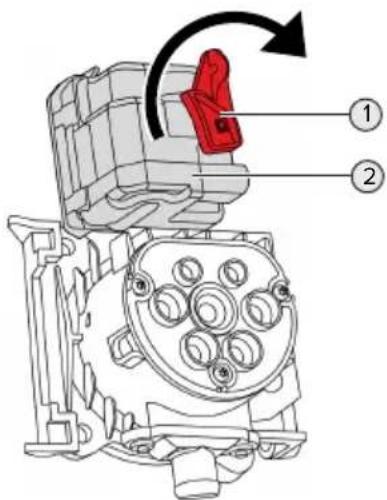
text_image
Technical diagram of a mechanical assembly with numbered components and directional arrow indicating rotation or movement.Fig. 25: Unlock the charging plug manually
▶ Open the product.
“5.5 Opening the product” [▶ 16]
▶ Loosen the red lever (1). The red lever is attached with a cable tie close to the actuator.
▶ Insert the red lever into the actuator (2).
▶ Turn the red lever 90^ in the clockwise direction.
▶ Unplug the charging plug.
Remove the red lever from the actuator and fasten it close to the actuator with a cable tie.
▶ Close the product.
“6.10 Closing the product” [▶ 36]
10 Taking out of service

The tasks described in this section may only be carried out by a qualified electrician.
▶ Disconnect the supply line and secure against reactivation.
▶ Open the product.
“5.5 Opening the product” [▶ 16]
▶ Disconnect the supply line and the control / data line (if applicable).
▶ Unfasten the product from the wall or from the stand system provided by MENNEKES.
▶ Run the supply line and the control / data line (if applicable) out of the housing.
▶ Close the product.
“6.10 Closing the product” [▶ 36]
10.1 Storage
Proper storage can positively affect and maintain the operability of the product.
▶ Clean the product before storing.
▶ Store the product in a clean and dry place in its original or other suitable packaging.
▶ Observe permissible storage conditions.
| Permissible storage conditions | ||
| Min. Max. | ||
| Storage temperature [°C] -30 +50 | ||
| Average temperature over 24 hours [°C] | +35 | |
| Altitude [m above sea level] 2,000 | ||
| Relative humidity (non-condensing) [%] | 95 | |
10.2 Disposal
▶ Comply with the statutory regulations and provisions for disposal and environmental protection in the country of use.
▶ Dispose of packaging sorted by type.

The product must not be discarded with household waste.
Recycling options for private households
EN
The product can be returned free of charge at the collection points operated by the public waste management authorities or at the disposal points established in accordance with Directive 2012/19/EU.
Recycling options for businesses
Details regarding commercial disposal are available from MENNEKES on request.
“1.2 Contact” [▶ 2]
Personal data / data protection
Personal data may be stored on the product. The end user is personally responsible for deleting the data.
11 EU Declaration of Conformity
MENNEKES Elektrotechnik GmbH & Co. KG declares that this product complies with Directive 2014/53/EU. The EU declaration of conformity can be found on our website in the download section for the selected product.
www.mennekes.org/emobility/products/portfolio/amtronr-wallboxes
Table des matières
text_image
Technical diagram of an open remote control box with numbered components for identificationtext_image
1. α = ~45° α 2xnatural_image
Line drawing of a device with attached cables and connectors (no text or symbols)text_image
Technical diagram of a device interior with labeled components and numbered calloutsnatural_image
Technical diagram of a car interior showing plug, cable, and wiring (no text or labels)text_image
Technical diagram of a vehicle interior with numbered components and red circles highlighting specific areastext_image
Diagram of a device rear panel with three labeled buttons: asterisk, double-headed arrow, and mouse cursor.natural_image
Technical line drawing of a car interior layout with numbered component (no text or symbols)text_image
Technical diagram of a car interior with labeled components and directional arrow indicating movement or forcetext_image
Technical diagram of an electrical connector with numbered parts and red circles highlighting specific componentshttps://www.mennekes.org/emobility/knowledge/compatible-meters/

natural_image
Line drawing of a device with attached cables and connectors (no text or symbols)natural_image
Line drawing of a backpack with a switch and cable, no text or symbols presenthttps://www.mennekes.org/emobility/knowledge/charge-point-labelling/

natural_image
Line drawing of a door handle with a red circle highlighting the side panel (no text or symbols)text_image
Technical diagram of a mechanical assembly with numbered components and directional arrow indicating rotation or movement.text_image
① ② ③ ④ ⑤ ⑥ MISHEEStext_image
Technical diagram of an open remote control box with numbered components for identificationtext_image
1. α = ~45° α 2xFig. 4: Desmontar la cubierta frontal - 1
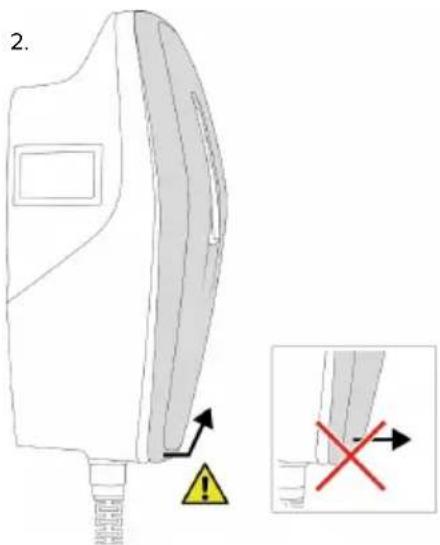
text_image
2. 1.0 1.0 1.0 1.0 1.0 1.0 1.0 1.0 1.0 1.0 1.0 1.0 1.0 1.0 1.0 1.0 1.0 1.0 1.0 1.0 1.0 1.0 1.0 1.0 1.0 1.0Fig. 5: Desmontar la cubierta frontal - 2
natural_image
Line drawing of a medical device with attached tubing and connectors (no text or symbols)text_image
Technical diagram of a device internal structure with labeled components and numbered annotationnatural_image
Technical diagram of a car's internal components showing wiring and connectors (no text or labels)text_image
Technical diagram of a vehicle interior with numbered components and red circles highlighting specific areastext_image
Diagram of a device rear panel with three labeled buttons: asterisk, double-headed arrow, and mouse cursor.text_image
Technical diagram of a vehicle interior with labeled components and numbered annotationFig. 14: Conexión Ethernet
text_image
Technical diagram of a car interior with labeled components and directional arrow indicating movement or forcetext_image
Technical diagram of an electrical switchgear with numbered components and red-circled annotationsFig. 16: Conexión entrada Downgrade
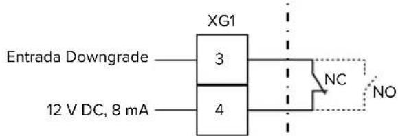
text_image
Entrada Downgrade XG1 3 4 NC NO 12 V DC, 8 mAnatural_image
Line drawing of a device with multiple cables and connectors, no text or symbols presentnatural_image
Line drawing of a device rear panel with a switch and arrow indicator (no text or symbols)text_image
Diagram illustrating a medical procedure with labeled components and warning indicators, including a red circular mark and yellow warning signs.natural_image
Line drawing of a door handle with a red circle highlighting the side (no text or symbols)text_image
Technical diagram of an engine component with labeled parts and directional arrow indicating rotation or movement.text_image
① ② ③ ④ ⑤ ⑥ MISHEESFig. 2: Vista esterna (esempio)
text_image
Technical diagram of an open remote control box with numbered components for identificationFig. 3: Vista interna (esempio)
text_image
1. α = ~45° α 2xFig. 4: Staccare la copertura anteriore - 1

text_image
2.Fig. 5: Staccare la copertura anteriore - 2
natural_image
Line drawing of a handheld electronic device with cables and connectors (no text or symbols)text_image
Technical diagram of a device interior with labeled components and numbered annotationnatural_image
Technical diagram of a car electrical connector with color-coded wires and wiring (no text or labels)text_image
Technical diagram of a car interior with numbered components and highlighted areastext_image
Diagram of a device rear panel with three labeled buttons: asterisk, double-headed arrow, and mouse cursor.text_image
Technical diagram of a vehicle interior with labeled components and numbered annotationFig. 14: Porta Ethernet
text_image
Technical diagram of a car interior with labeled components and directional arrow indicating movement or forceIT
text_image
Technical diagram of an electrical connector with numbered parts and red annotations highlighting specific components.natural_image
Line drawing of a device with attached cables and connectors (no text or symbols)natural_image
Line drawing of a device rear panel with a button and cable (no text or symbols)natural_image
Line drawing of a device rear panel with a red circular mark on the side (no text or symbols)text_image
Technical diagram of a mechanical assembly with numbered components and directional arrow indicating rotation or movement.5.4 Frontcover losmaken 17
5.5 Product openen.... 18
"1.1 Homepage" [▶ 2]
1.3 Waarschuwingen
text_image
Technical diagram of an electronic device with numbered components for identification"1.1 Homepage" [▶ 2]
5.4 Frontcover losmaken
text_image
1. α = ~45° α 2xAfb. 4: Frontcover losmaken - 1
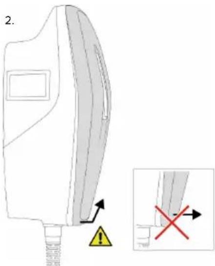
text_image
2.Afb. 5: Frontcover losmaken - 2
natural_image
Line drawing of a handheld electronic device with cables and connectors (no text or symbols)text_image
Technical diagram of a device interior with labeled components and numbered annotationnatural_image
Technical diagram of a car electrical connector with color-coded wires and wiring (no text or labels)text_image
Technical diagram of a vehicle interior with numbered components and highlighted areas"6.9 Product testen" [▶ 37]
text_image
Diagram of a device rear panel with three labeled buttons: (*) and (=), marked with red circles and symbols.natural_image
Technical line drawing of a car interior with labeled components (no text or symbols present)text_image
Technical diagram of a vehicle's rear intake and exhaust system with numbered componentstext_image
Technical diagram of an internal electrical or mechanical device with numbered components and highlighted areasnatural_image
Line drawing of a device with attached cables and connectors (no text or symbols)natural_image
Line drawing of a device rear panel with a switch and arrow indicator (no text or symbols)text_image
Diagram illustrating a medical procedure on a device with warning symbols and labeled parts, including a red circular mark and directional arrows.natural_image
Line drawing of a device's front panel with a red circle highlighting a specific area (no text or symbols present)"1.1 Homepage" [▶ 2]
8.2 Reiniging
GEVAAR
"1.1 Homepage" [▶ 2]
"1.1 Homepage" [▶ 2]
9.1 Reserveonderdelen
text_image
Technical diagram of an engine component with numbered parts and directional arrow indicating rotation or assembly.Afb. 25: Laadstekker handmatig ontgrendelen
"8.1 Service" [▶ 41]
text_image
Technical diagram of an electronic device with numbered components for identificationtext_image
1. α = ~45° α 2xFig. 4: Løsne front coveret - 1

text_image
2.Fig. 5: Løsne front coveret - 2
natural_image
Line drawing of a device with attached cables and a control panel (no text or symbols)Fig. 6: Åbne produktet (eksempel)
text_image
Technical diagram of a device interior with labeled components and numbered annotationFig. 9: Lukkepropper (eksempel)
natural_image
Technical line drawing of a mechanical component with colored connectors and tubing (no text or symbols)Fig. 10: Tilslutning strømforsyning (eksempel)
▶ Afisolér forsyningskablet.
▶ Afisolér ledere 12 mm.

text_image
Technical diagram of a vehicle interior with numbered components and highlighted areastext_image
Diagram of a device rear panel with three labeled buttons: asterisk, plus, and minus symbols.text_image
Technical diagram of a vehicle interior layout with labeled components and numbered annotationFig. 14: Ethernet-tilslutning
text_image
Technical diagram of a car interior with labeled components and directional arrows indicating movement or flow.text_image
Technical diagram of an electronic device rear panel with numbered components and highlighted areasFig. 16: Tilslutning downgrade-indgang
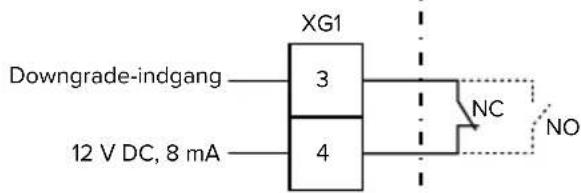
text_image
Downgrade-indgang 3 4 XG1 NC NO 12 V DC, 8 mAFig. 17: Principskema: tilslutning af en ekstern omskifterkontakt (standardindstilling: NO)
natural_image
Line drawing of a medical device with attached tubing and connector points (no text or symbols)natural_image
Line drawing of a device rear panel with cable and a small component on top (no text or symbols)Fig. 20: Fjerne beskyttelsesfolien (eksempel)
6.11 Montering af front cover
text_image
Diagram illustrating a medical or safety procedure with labeled components and warning indicatorsFig. 21: Anbringe front cover - 1
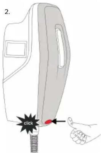
text_image
2. clickFig. 22: Anbringe front cover - 2
Anbring front coveret, og lad det gå i indgreb.
https://www.mennekes.org/emobility/knowledge/charge-point-labelling/

natural_image
Line drawing of a device rear panel with a red circle highlighting a specific area (no text or symbols)text_image
Technical diagram of an engine component with numbered parts and directional arrow indicating rotation or assembly.text_image
Technical diagram of an electronic device with numbered components for identificationFig. 3: Insidan (exempel)
text_image
1. α = ~45° α 2xFig. 4: Lossa frontkåpan – 1
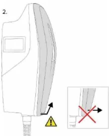
text_image
2.Fig. 5: Lossa frontkåpan – 2
natural_image
Line drawing of a device with multiple cables and a central panel, no text or symbols presenttext_image
Technical diagram of a device interior with labeled components and numbered annotationnatural_image
Technical diagram of a car's internal components showing wiring and connectors (no text or labels)text_image
Technical diagram of a vehicle interior with numbered components and red circles highlighting specific areastext_image
Diagram of a device rear panel with three labeled buttons (asterisk, minus sign, hash) pointing to the right side.text_image
Technical diagram of a vehicle interior with labeled components and numbered annotationFig. 14: Ethernet-anslutning
text_image
Diagram of a car interior with labeled components and a directional arrow indicating movement or force.Fig. 15: Anslut dataledning (exempel)
text_image
Technical diagram of an electronic device rear panel with labeled components and a red circle highlighting a component.Fig. 16: Anslutning av downgrade-ingång
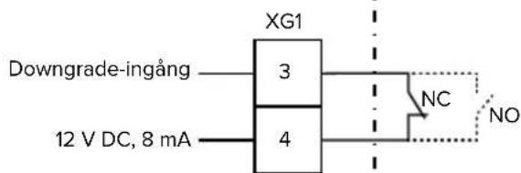
text_image
XG1 Downgrade-ingång —— 3 12 V DC, 8 mA —— 4 NC NOhttps://www.mennekes.org/emobility/knowledge/compatible-meters/
natural_image
Line drawing of a medical device with attached tubing and connector points (no text or symbols)natural_image
Line drawing of a device rear panel with cable and switch (no text or symbols)text_image
Diagram illustrating a medical or safety procedure with warning symbols and labeled parts, including a red circular marker and directional arrows.https://www.mennekes.org/emobility/knowledge/charge-point-labelling/

natural_image
Line drawing of a device rear panel with a red circle highlighting a specific area (no text or symbols present)text_image
Technical diagram of a mechanical assembly with numbered components and directional arrow indicating rotation or movement.text_image
Technical diagram of an electronic device with numbered components for identificationtext_image
1. α = ~45° α 2xnatural_image
Line drawing of a device with cables and connectors, no text or symbols presenttext_image
Technical diagram of a device interior with labeled components and numbered annotationnatural_image
Diagram of a car's internal components showing wiring and connectors (no text or labels)text_image
Technical diagram of a vehicle interior with numbered components and highlighted areastext_image
Diagram of a device control panel with three labeled buttons: (*) and (=), marked with red circles and arrows.natural_image
Technical line drawing of a vehicle interior with labeled components (no text or symbols present)text_image
Technical diagram of a vehicle's rear intake and exhaust system with labeled componentstext_image
Technical diagram of an electronic device rear panel with numbered components and highlighted areasnatural_image
Line drawing of a device with cables and connectors, no text or symbols presentnatural_image
Line drawing of a device rear panel with cable and switch (no text or symbols)text_image
Diagram illustrating a hand operating a device with warning labels and directional arrows indicating movement or safety.natural_image
Line drawing of a door handle with a red circle highlighting the side (no text or symbols)text_image
Technical diagram of an engine component with numbered parts and directional arrow indicating rotation or assembly.text_image
Technical diagram of an electronic device with numbered components for identificationtext_image
1. α = ~45° α 2xnatural_image
Line drawing of a device with multiple cables and connectors, no text or symbols presenttext_image
Technical diagram of a device interior with labeled components and numbered annotationnatural_image
Technical diagram of a car electrical connector with color-coded wires and wiring (no text or labels)text_image
Technical diagram of a car interior with numbered components and highlighted areastext_image
Diagram of a device rear panel with three labeled buttons (asterisk, circle, hash) pointing to the screen.text_image
Technical diagram of a vehicle interior with labeled components and numbered annotationtext_image
Technical diagram of a car interior with labeled components and directional arrows indicating movement or flow.text_image
Technical diagram of an automotive electrical panel with numbered components and highlighted areashttps://www.mennekes.org/emobility/knowledge/compatible-meters/