AMTRON Professional 22 - Electric charging station Mennekes - Free user manual and instructions
Find the device manual for free AMTRON Professional 22 Mennekes in PDF.

User questions about AMTRON Professional 22 Mennekes
0 question about this device. Answer the ones you know or ask your own.
Ask a new question about this device
Download the instructions for your Electric charging station in PDF format for free! Find your manual AMTRON Professional 22 - Mennekes and take your electronic device back in hand. On this page are published all the documents necessary for the use of your device. AMTRON Professional 22 by Mennekes.
USER MANUAL AMTRON Professional 22 Mennekes
Operating and installation manual
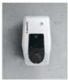
natural_image
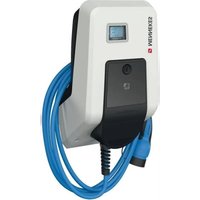
White MINNEES electric vehicle charging station with blue cable, mounted on a concrete wall (no visible text or symbols)Inhaltsverzeichnis
5 Installation....12
5.1 Standortwahl 12
8.3 Firmware Update....37
9 Störungsbehebung....37
https://www.chargeupyourday.com/faqs/

1.2 Warnhinweise
text_image
Diagram of a device with labeled parts including an RFID scanner, memory card, and various electronic components.text_image
Diagram of a device control panel with numbered labels pointing to ports and indicatorstext_image
Technical diagram of a remote control device with numbered components for identificationAbb. 4: Rückansicht
text_image
Technical diagram of an electronic device rear panel with numbered components for identificationnatural_image
White medical device with blue cable and connector, no visible text or symbolsnatural_image
Person interacting with a MINIKES brand charging station (no visible text or symbols on device)natural_image
White medical device with blue cable and connector, no visible text or symbols
natural_image
White electronic device with a black lid and indicator lights, placed on a plain surface (no visible text or symbols)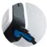
natural_image
White and black handheld device with a small vent and control panel (no visible text or symbols)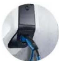
text_image
Technical diagram of a mechanical assembly with numbered components and directional arrows indicating motion or movement.text_image
Technical diagram of a tank with numbered components and exploded view, likely for assembly or maintenance instructions.text_image
Technical diagram showing labeled components of an electrical or mechanical device with numbered parts and connection detailstext_image
L3 X L2 X L1 X SOR74 1 3 N X X 16 15 18text_image
Charging station interface 192.168.123.123/operator/settings MENNEKES Charging station interface 4.50-5211 State Settings ► Default Operator System Documentation OCFP ChargePointID ChargePointID APTRION The at that is sent to the backend and used by the backend to verify the charge point - show more. 234 Connection Type GSM The type of data connection to be used to connect to the backend system, if any. Use this option to disable backend communications completely. Access Point Name (API) chargecloudie Access Point Name of the mobile network to be used when establishing connectors to the backend system are the fault-in modem. APNI Username Username to be used for authenticating with the Access Point of the mobile network for connecting with the backend systems. APNI Password Password to be used for authenticating with the Access Point of the mobile network for connecting with the backend systems. Save Save & Restart Settings Default & Resortnatural_image
Line drawing of a device with a plug inserted into the socket (no text or symbols visible)text_image
I >15 mm *klack* *klack*| ... Error activation message | ... | Corrective actions |
| ... ... ... ... | ||
| ... Residual current detected via sensor | ... | The saftey mechanism is reset to its original state every time the plug is removed and automatically after 15 minutes if the plug is not removed. If problem persists check yellow current transformer and its connection. |
| ... ... ... ... ... |

text_image
Technical diagram of a mechanical assembly with labeled parts, showing internal components and a zoomed-in detail view.1 About this document....2
1.1 Service....2
1.2 Warning information....2
1.3 Symbols used....3
2 For your safety....3
2.1 Target groups....3
2.2 Intended use....3
2.3 Improper use 4
2.4 Basic safety information....4
2.4.1 Qualification....4
2.4.2 Proper condition....4
2.4.3 Observing supervisory duties....4
2.4.4 Proper use of charging cable....5
2.4.5 Keeping order....5
2.5 Safety labels....5
3 Product description....6
3.1 Type plate 6
3.2 Delivery content 7
3.3 Device layout 7
3.4 Cable suspension....8
3.5 Energy meter....8
3.6 Multifunction button 9
3.7 Operating modes....9
3.8 LED Info bar....9
3.9 Device variants....10
4 Technical data....11
5 Installation....12
5.1 Choice of location....12
5.2 Permitted environmental conditions....12
5.3 Preliminary tasks on the indoor installation.....13
5.3.1 Laying the supply line....13
5.3.2 Providing fuse protection....13
5.4 Opening the device....14
5.5 Mounting the device on the wall....15
5.6 Electrical connection....16
5.6.1 Power supply....16
5.6.2 Shunt release....16
5.7 Setting up the device for three-phase operation...17
6 Commissioning....17
6.1 Setting up a connection to the ECU....17
6.2 Configuring via the web interface....18
6.2.1 Operating mode "Autostart"....19
6.2.2 Operating mode "Local Whitelist" 19
6.2.3 Operating mode "Backend-System"....20
6.2.4 Operating mode "Networked" 21
6.2.5 Setting the maximum charging current 21
6.2.6 Advanced settings....21
6.3 Inserting the SIM card....30
6.4 Switching on the device.... 31
6.5 Monitoring the power supply....31
6.6 Checking the device 32
6.7 Closing the device....32
7 Operation....33
7.1 Authorization....33
7.2 Charging the vehicle....33
7.3 Multifunction button 34
7.3.1 Restarting residual current device and circuit breaker 34
7.3.2 Checking the residual current device 35
8 Maintenance....35
8.1 Servicing....35
8.2 Cleaning 36
8.3 Firmware Update....37
9 Remedy....37
9.1 Fault messages....37
9.2 Spare parts.... 38
9.3 Unlock the charging plug 38
10 Taking out of service and dismantling 39
11 Storage 39
12 Disposal....39
13 Accessories....39
14 Glossary....40
1 About this document
The AMTRON ^® , hereafter referred to as "device", is available in various variants. You can find the version of your device on the type plate. This document refers to the following versions of the device:
■ AMTRÖProfessional+ E 7,4 / 22
■ AMTRÖProfessional+ 7,4 / 22
■ AMTRÖProfessional+ 7,4 / 22 PnC
■ AMTRÖProfessional E 7,4 / 22
■ AMTRÖProfessional 7,4 / 22
The above variants are also available with the necessary default settings for connection to the billing service MENNEKES ativo. This manual also applies to the ativo variants.
This manual is intended for use by the operator and qualified electrician(s). It contains instructions for safe operation and installation. Tasks that may only be carried out by a qualified electrician are specially marked.
Observe all additional documentation for the use of the device. Keep all documents for later reference and pass these on to the new operator.
The German version of this manual is the original manual. Manuals in other languages are translations of this original manual.
Copyright © 2019 MENNEKES Elektrotechnik GmbH & Co. KG
1.1 Service
If you have questions concerning the device, please contact MENNEKES or your responsible service partner. On our homepage in "Search for Partners" you will find further contacts in your country.
Use the form in "Contact" on for a direct contact to MENNEKES.
https://www.chargeupyourday.com/

Please have the following information ready to hand for quick processing:
■ Type designation / serial number (see type plate on the device)
Further information on the subject of electromobility is provided on our website under "FAQ"
https://www.chargeupyourday.com/faqs/

1.2 Warning information
Warning of personal injury
ANGER
This warning notice indicates imminent danger that will result in death or severe injuries.
WARNING
This warning notice indicates a dangerous situation that may result in death or severe injuries.
AUTION
This warning notice indicates a dangerous situation that can result in minor injuries.
Warning of material damage
ATTENTION
This warning notice indicates a dangerous situation that may result in property damage.
2 For your safety
1.3 Symbols used

Only a qualified electrician may carry out operations marked with this symbol.

This symbol indicates an important note.

The symbol indicates additional, useful information.
This symbol marks a prompt for action.
■ This symbol marks a listing.
→ This symbol is used to refer to another section in this manual.
This symbol is used to refer to another document.
This symbol is used to point out a result.
2.1 Target groups
Owner
As the owner / operator, you are responsible for the device. You are responsible for proper and safe use of the device. This includes instructing persons who use the device.
As an owner / operator without electrical engineering training, you are only allowed to execute simple activities that do not require a qualified electrician.
Qualified electrician

As a qualified electrician, you have received recognised training in electrical engineering. Based on this knowledge, you are authorized to carry out the electrical work requested in this manual.
Requirements for qualified electricians:
■ Knowledge of general and special regulations pertaining to safety and accident prevention.
■ Knowledge of electrical regulations.
■ Knowledge of national regulations.
■ Ability to identify risks and avoid possible hazards.
2.2 Intended use
The device is a charging station for use in the private and semi-public sphere with limited access, such as private property, company car parks or municipal depots.
The device is intended exclusively for the charging of electric vehicles.
■ Charging in accordance with Mode 3, as stipulated in IEC 61851-1 for vehicles with batteries that do not generate gas.
■ Plugs and sockets according to IEC 62196.
Vehicles with batteries that generate gas cannot be charged.
The unit is intended for permanent installation and for indoor and outdoor use.
The device can be used as a standalone device or in a network of several devices. If required, the device can be connected to a Backend-System, e.g. the chargecloud.
In some countries there are statutory regulations that require the charging point to switch to a de-energised state, as soon as a load contactor sticks (welding detection). A shunt release switches the charging point to de-energised status if an error occurs.
Legal requirements in some countries provide additional protection against electric shock. A possible additional protective measure can be the use of a shutter.
The device may only be operated taking into account all international and national regulations. Please observe the following international regulations or the respective national transposition:
IEC 61851-1
IEC 62196-1
IEC 60364-7-722
Read and observe these instructions as well as all additional documentation for the use of the device.
2.3 Improper use
Using the device is safe only when used as intended.
Any other use, as well as changes to the device, are considered non-intended use and therefore are not permitted.
The owner / operator is responsible for the intended and safe use. MENNEKES Elektrotechnik GmbH & Co. KG accepts no liability for any consequences arising from non-intended use of the device.
2.4 Basic safety information
2.4.1 Qualification
Some activities in this manual require expertise in electrical engineering. Performing activities in the absence of knowledge or lack of qualifications can result in serious accidents and death.
▶ Only carry out tasks for which you are qualified and have been instructed.
▶ Note the references to a qualified electrician in this manual.
2.4.2 Proper condition
Damaged device
If the device is damaged or defective, has a defective housing or missing components, people can be seriously injured by electric shock.
▶ Avoid collisions and improper handling.
▶ Do not use the device in case of damage / defects.
▶ Mark a damaged device, so that other persons cannot use it.
▶ Have a qualified electrician rectify the damage without delay.
Improper maintenance
Improper maintenance can affect the safety of the equipment and cause accidents. This can seriously injure or kill people.
▶ Observe the maintenance schedule.
▶ Commission a qualified electrician to perform regular maintenance.
2.4.3 Observing supervisory duties
Persons, especially children, and animals who are not fully able to assess potential hazards pose a danger to themselves and to others.
▶ Keep away from the device and charging cable.
- Keep animals away from the device and charging cable.
2.4.4 Proper use of charging cable
Improper handling of the charging cable can cause hazards such as electric shock, short circuit or fire.
▶ Do not touch the contact pins.
▶ Do not use adaptor connectors or extension cables.
▶ Avoid kinks, sharp edges, loads and impacts.
▶ Avoid knotting of the charging cable.
▶ Unroll the charging cable completely when charging.
▶ Remove the charging cable only by pulling the plug from the charging socket.
▶ If the charging cable is not in use, fit on the protective cap.
▶ Do not expose the charging cable to tensile stress.
2.4.5 Keeping order
A charging cable lying around presents a stumbling hazard. Objects on the device may fall.
▶ Minimise stumbling hazard.
▶ After charging store the charging cable properly or use the cable suspension.
▶ Do not store any objects on the device.
2.5 Safety labels
Safety labels that warn of hazardous situations are affixed on some of the device components. If the instructions on the safety labels are not complied with severe or fatal injuries can occur.
EN
| Safety labels | |
| Symbol Meaning | |
 | Danger - high voltage▶ Prior to performing tasks on the device, ensure that it is de-energi-sed. |
 | Danger if the instructions in the accompanying documents are not complied with.▶ Prior to performing tasks on the device, read the accompanying documents, particularly the installation and operating manual. |
▶ Comply with the instructions on the safety labels.
▶ Clean contaminated safety labels to keep them legible. When cleaning do not use aggressive cleaning agents.
▶ Replace safety labels that have been damaged or have become unreadable.
▶ After replacement, affix the intended safety labels on spare parts or accessories.
3 Product description
Equipment features
■ Charging powers up to 7.4 kW (single-phase) / 22 kW (three-phase).
■ Communication between device and vehicle according to ISO 15118. *
■ Accessory kit for local networking of multiple devices (not installed).
■ Authorisation via Backend-System or RFID card (ISO 14443A / MIFARE classic and MIFARE DESFire).
■ Integrated modem for mobile network standards 4G (LTE), 3G (UMTS) and 2G (GSM). *
■ Compatible with OCPP 1.5 and OCPP 1.6.
■ MENNEKES ECU, Electronic Control Unit.
■ Status information via LED information panel.
■ Integrated MiD energy meter.
■ Circuit breaker. *
■ Type A residual current device. *
■ DC residual current monitoring > 6 mA.
■ Integrated shunt release (for welding detection). *
■ Relay for connection of an external shunt release (for welding detection). *
■ Unlocking function in the event of a power failure (only for devices with Type 2 charging socket).
■ Phase sequence relay. *
■ Temperature monitoring.
■ Integrated cable storage.
■ Wired ready for connection.
*optional
Optional equipment
| Professional+ E 7,4 / 22 | Professional+ 7,4 / 22 | Professional+ 7,4 / 22 PnC | Professional E 7,4 / 22 | Professional 7,4 / 22 | |
| Communication according to ISO 15118 | -- x -- | ||||
| Integrated modem | x x x -- | ||||
| Circuit breaker | - x x - x | ||||
| Type A residual current device | - x x - x | ||||
| Shunt release | -XX-X | ||
| Relay for shunt release | X--X- | ||
| Phase sequence relay | -XX-X |
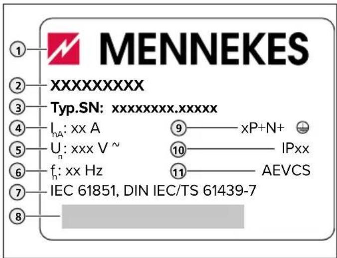
3.1 Type plate
The type plate contains all important device data. The type plate shown is an example.
▶ Note the type plate on your device. The type plate is located at the top on the lower enclosure part.
text_image
MENNEKES ① ② XXXXXXXXX ③ Typ.SN: xxxxxxxx.xxxxxx ④ IₙA: xx A ⑤ Uₙ: xxx V ~ ⑥ fₙ: xx Hz ⑦ IEC 61851, DIN IEC/TS 61439-7 ⑧ ⑨ xP+N+ ⑩ IPxx ⑪ AEVCSFig. 1: Type plate (pattern)
- Manufacturer
- Type
- Item / serial number
- Rated current
- Rated voltage
- Rated frequency
- Standard
- Barcode
- Number of phases
- Degree of protection
- Information
3.2 Delivery content
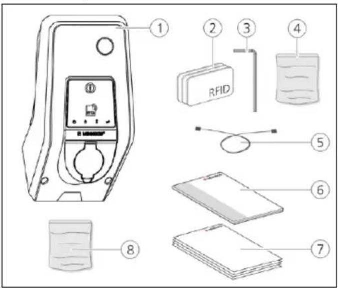
text_image
Diagram of a device with labeled parts including an RFID device, battery, and various electronic components.Fig. 2: Delivery content (example)
- Device
- 3x RFID card
- Allen key
- Bag with installation hardware (screws, dowels, sealing plugs)
- USB cable
- Operating and installation manual
-
Accompanying documents:
Set-up data sheet
Drilling template
Circuit diagram
Test report
Supplier documentation -
Accessory kit for local networking of multiple devices (USB-Ethernet-Adapter, antenna extension if required, split ferrite, installation manual)
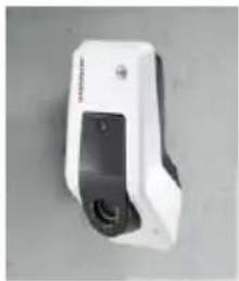
3.3 Device layout
The enclosure of the device has three parts and consists of lower enclosure part, upper enclosure part and front panel. The design of the front panel depends on the version of the device.
→ "3.9 Device variants"
Front view
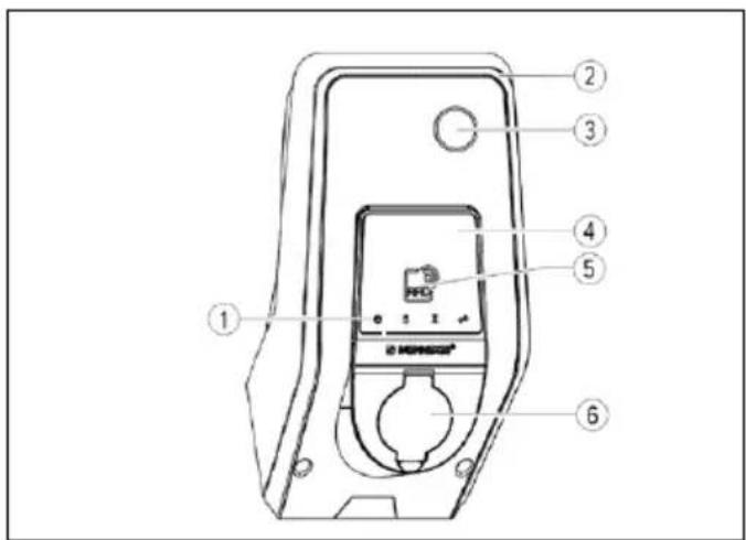
text_image
Technical diagram of a device control panel with numbered labels pointing to ports and indicatorsFig. 3: Front view (example)
- LED Info bar
- Upper enclosure part
- Inspection window for energy meter
- Front panel
- RFID card reader
- Type 2 charging socket with hinged lid
1) Depending on the variant
→ "3.9 Device variants"
Rear view
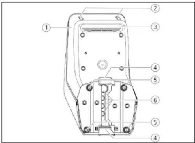
text_image
Technical diagram of a remote control device with numbered components for identificationFig. 4: Rear view
- Lower enclosure part
- Fastening screws for upper enclosure part
- Air outlet
- Pre-punched aperture for supply line / cable duct
- Fastening bores for mounting
- Cable glands
Interior view of lower enclosure part
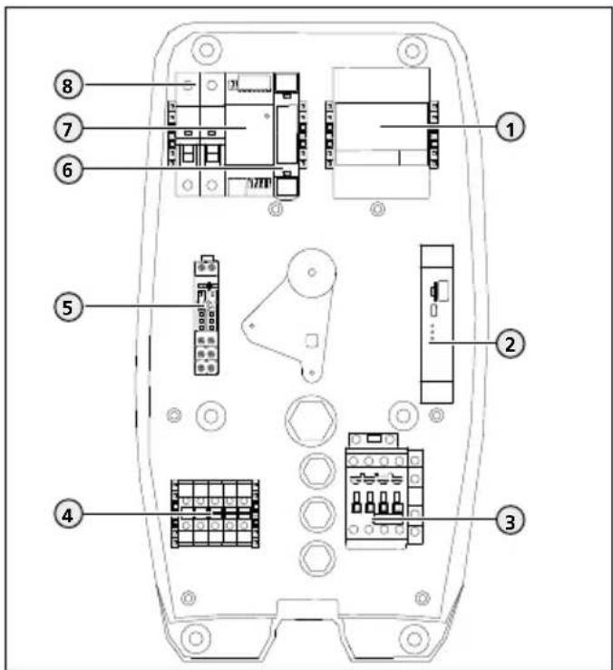
text_image
Technical diagram of an electronic device rear panel with numbered components for identificationFig. 5: Inside view (example: version Professional+ E 7,4 / 22)
- Energy meter
- ECU
- Charging contactor point
- Terminals for voltage supply
- Relay for shunt release 1)
- Actuator controller 2)
- Power adapter
- Control fuse
^1) For versions Professional(+) E 7,4 / 22 only
2) For versions with Type 2 charging socket only
→ "3.9 Device variants"
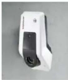
3.4 Cable suspension
The charging cable can be hung directly on the housing.
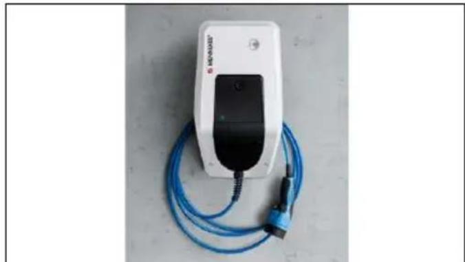
natural_image
White electric vehicle charging station with blue cable, no visible text or symbols on device bodyFig. 6: Cable suspension
3.5 Energy meter
Energy consumption can be read-out on the energy meter.
text_image
MENNEKES®Fig. 7: Energy meter
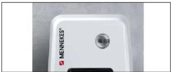
3.6 Multifunction button
For versions Professional(+) 7,4 / 22 (PnC) only.
The residual current device and the miniature circuit breaker in the device can be manually switched on again from outside via the multifunction button. The residual current device can be tested for functionality using the multifunction button without opening the housing.
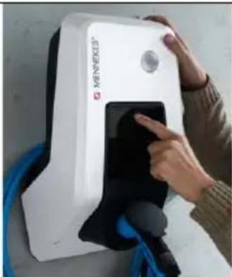
natural_image
Person interacting with a white MKNIKES® medical device, no visible text or symbols on the device itselfFig. 8: Multifunction button
3.7 Operating modes
The device has various operating modes that can be changed even during operation.

The availability of the individual operating modes depends on the configuration of the device.
The following operating modes are possible:
■ "Autostart"
The device is operated as a stand-alone solution without connection to a Backend-System. An authorisation is not required.
■ "Local Whitelist"
The device is operated as a stand-alone solution without connection to a Backend-System. Authorisation occurs via RFID cards and a local Whitelist.
■ "Backend-System"
The device is connected to the Backend-System via OCPP. The device is operated via the Backend-System.
■ "Networked"
Several devices are connected via ethernet to enable use of local load management and to establish a
connection to the Backend-System for all networked devices.
Requirements:
The accessory kit for local networking of multiple devices is installed.
Multiple devices are networked.
Installation manual of the accessory kit.
EN
3.8 LED Info bar
The LED information field indicates the operating status of the device. Standby, charging, wait time, and fault are indicated by four symbols in the colours blue, green, white, and red.
Symbol Colour Operating state

Lights up blue
Standby
The device is ready for use. No vehicle is connected to the device.

flashes blue
Standby: Starting the charging process
■ Authorisation has occurred. No vehicle is connected to the device.
■ Authorisation has not occurred. A vehicle is connected to the device.

Lit green
Charging
Charging in progress.

flashes green
Charging: Excess temperature warning
Charging in progress. The device reduces the charging current to prevent overheating and deactivation.

steady white
Wait period
■ The charging process on the device was ended. Waiting for confirmation from the vehicle.
■ Waiting for authorisation.
flashes white
Wait time: Removing the charging cable
The charging process has finished. Remove the charging cable.

lit or flashing red
Fault
A fault prevents the vehicle from charging.
→ "9 Remedy"
The colours green and blue can be configured when the device is commissioned.
→ "6.2.6 Advanced settings"
3.9 Device variants
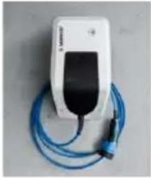
natural_image
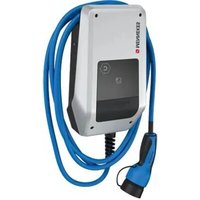
White medical device with black cover and blue cord, connected by a blue cable (no visible text or symbols)
Permanently connected charging cable with type 2 charging connector
These variants have a permanently connected charging cable. They can be used to charge all electric cars equipped with type 2 plug. You do not need to use a separate charging cable.

natural_image
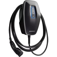
White handheld device with a black lid and circular button, placed on a plain surface (no visible text or symbols)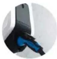
Type 2 charging socket with hinged lid for use with separate charging cable
These variants have a Type 2 charging socket with hinged lid for use with separate charging cables. They can be used to charge all electric cars equipped with type 2 or type 1 plug.
natural_image
White handheld device with black buttons and a small screen, isolated on neutral background (no visible text or symbols)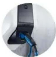
Type 2 charging socket with shutter for use with separate charging cable
For versions Professional(+) E 7,4 / 22 only.
These versions have a type 2 charging socket with shutter for use with separate charging cables. The shutter provides additional protection against electric shock and is legally prescribed in some countries.
→ "2.2 Intended use"
They can be used to charge all electric cars equipped with type 2 or type 1 plug.
All charging cables from MENNEKES can be found on our website under "Charging cables".
https://www.chargeupyourday.com/

4 Technical data
| Professional(+) (E) 7,4 / 22 (PnC) | ||
| Charging power Mode 3 [kW] * | up to 22 | |
| Rated voltage UN [V] AC ±10 % | 400 | |
| Rated frequency fN [Hz] | 50 | |
| Rated current INA [A] | 32 | |
| Maximum backup fuse [A] According to type plate / configuration | ||
| Protection degree | ■ Device with permanently connected charging cable: IP 4■ Device with hinged lid: IP 54 | |
| Protection class II | ☐ | |
| Dimensions H x W x D [mm] 474 x 259 x 220 | ||
| Weight [kg] | ■ Device with permanently connected charging cable: 8■ Device with hinged lid: 5.5 | |
| Rated insulation voltage Ui [V] | 500 | |
| Rated impulse withstand voltage Uimp [kV] | 4 | |
| Rated current of charging points circuit Iinc [A] | 32, 1 ph / 3 ph | |
| Rated conditional short-circuit current of charging points circuit Icc [kA] | 10 | |
| Rated diversity factor RDF 1 | ||
| Pollution degree 3 | ||
| Overvoltage category III | ||
| Types of system earthing | TN / TT (IT only under certain conditions see "5.6.1 Power supply") | |
| Installation Outdoor or indoor | ||
| Stationary or movable Stationary | ||
| Usage AEVCS | ||
| External design | Wall mounted | |
| EMC classification | A+B | |
| Mechanical impact protection | IK10 | |
| Terminals for supply line | Terminals [mm2] | 10 |
| Clamping range [mm2] | rigid 5 x 10flexible 5 x 6 | |
| Tightening torque [Nm] | max. 1.8 | |
| Relay shunt release | Clamping range [mm2] | rigid 1 x 6flexible 1 x 4 |
| Tightening torque [Nm] | 0.8 | |
| Standard | EN 61851, DIN IEC / TS 61439-7 | |
EN
* The device can be operated in single-phase or three-phase.
5 Installation

The activities described in this section must only be executed by a qualified electrician.
ATTENTION
Damage to the device by improper handling
Collisions and shocks may damage the device.
▶ Avoid collisions and impacts.
▶ Use a soft base to set down the device.
▶ Do not use the bolts for fastening the front panel as a transport aid or handle.
5.1 Choice of location
The unit is intended for permanent installation and for indoor and outdoor use. A suitable location meets the following requirements:
■ Technical data and mains data are the same.
→ "4 Technical data"
■ Permissible ambient conditions are observed.
→ "5.2 Permitted environmental conditions"
■ The following minimum distances to other objects (e.g. walls) must be complied with:
Distance to the left and right: 300 mm Distance upward: 300 mm
■ Operating mode "Backend-System": The mobile network for connection to the Backend-System must be fully available at the location.
■ “Networked” operating mode: Networked devices are in sufficient proximity to each other (The Ethernet cable may not exceed 100 m in length).
■ The device and the charging station are in sufficient proximity to each other, depending on the charging cable used.
5.2 Permitted environmental conditions
ANGER
Danger of injury and fire
If the device is operated in potentially explosive atmospheres (explosive area), explosive substances may ignite due to sparking of components of the device.
▶ Do not use charging cable in potentially-explosive atmospheres (e.g. at gas filling stations)
ATTENTION
Device damage due to unsuitable ambient conditions
Unsuitable ambient conditions can result in device damage.
▶ Avoid direct sunlight.
▶ Protect the device from a direct water jet.
▶ Ensure adequate ventilation of the device. Do not install in niches.
▶ Keep device away from heat sources.
▶ Avoid strong temperature fluctuations.
Permitted environmental conditions
| Ambient temperature -25 ... +40 °C | |
| Average temperature over 24 hours | < 35 °C |
| Altitude Max. 2,000 m above sea level | |
| Relative humidity | max. 95% (non-condensing) |
5.3 Preliminary tasks on the indoor installation
!ANGER
Fire hazard due to overload
There is a fire hazard caused by unsuitable circuit breaker and supply line.
▶ Configure the circuit breaker and the supply line according to the technical data and the configuration of the device.
→ "4 Technical data"
5.3.1 Laying the supply line
▶ Configure the supply line according to the technical data of the device.
→ "4 Technical data"

When dimensioning the supply line (cross section and cable type), always ensure the following local conditions:
■ Type of installation
■ Cable parameters per unit length
■ Line length
▶ Lay out the supply line to the desired location. The device can be mounted on a wall or an stainless steel or concrete column from MENNEKES.
Wall installation - surface installation
For a surface installation, the pre-punched aperture on the upper enclosure part must be broken out.
Wall installation - concealed installation
For concealed installation the position of the supply line must be arranged using the provided drilling template or Fig. "Fig. 10: Drilling dimensions [mm]".
Mounting on a stainless steel or concrete column
If need be the device can be mounted on a stainless steel or concrete column.
The stainless steel or concrete columns are available from MENNEKES as accessories.
Installation manual for the stainless steel or concrete column.
Mounting on a pole
If needed, the device can be mounted onto a pole. The pole is available at MENNEKES as an accessory.
Installation manual from the pole
5.3.2 Providing fuse protection
Depending on the version, the device is equipped with a type A residual current device, a circuit breaker and a relay for connection of an external shunt release according to the table below.
| Professional+ E 7,4 / 22 | Professional+ 7,4 / 22 | Professional+ 7,4 / 22 PnC | Professional E 7,4 / 22 | Professional 7,4 / 22 | |
| Circuit breaker | - x x - x | ||||
| Type A residual current device | - x x - x | ||||
| Relay for shunt release | x - - x - |
Circuit breaker
For versions Professional(+) E 7,4 / 22 observe the following:
The required circuit breaker must be incorporated in the indoor installation.

■ The device must protected with a line circuit breaker rated at 32 A or less with C-characteristics.
The circuit breaker must be dimensioned with due consideration of the name plate, the required charging power, and the supply line (line length, cable cross-section) for the charging station in accordance with the national regulations.
■ One circuit breaker is required for each charging point.
Residual current device
For versions Professional(+) E 7,4 / 22 observe the following:
The required residual current device must be incorporated in the indoor installation (in accordance with IEC 60364-7-722 (in Germany in accordance with DIN VDE 0100-722)).

■ The device has a differential current sensor for DC residual current monitoring > 6 mA with tripping characteristics in accordance with IEC 62752.
At least one dedicated type B residual current circuit breaker has to protect the device if it is subject to the scope of IEC 60364-7-722:2018.
At least one dedicated type A residual current circuit breaker has to protect the device if it is subject to the scope of HD 60364-7-722:2016.
■ No other circuits may be connected to this residual current circuit breaker.
■ Compliance with national regulations is mandatory.
Shunt release
For versions Professional(+) E 7,4 / 22 observe the following:
▶ Check whether a shunt release is legally prescribed in the country of use.
→ "2.2 Intended use"
The required shunt release must be incorporated in the indoor installation.

■ The shunt release must be positioned next to the circuit breaker.
■ The shunt release and the circuit breaker must be compatible with each other.
5.4 Opening the device
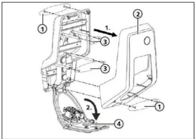
text_image
Technical diagram of a mechanical assembly with numbered components and directional arrows indicating motion or movement.Fig. 9: Opening the device
When delivered, the upper enclosure part (2) is not attached with screws. The screws (1) are stored in the enclosed accessory bag.
▶ Switch off the power supply.
▶ Unscrew screws (1) if necessary.
▶ Remove the upper enclosure part (2).
▶ Unscrew screws (3) and swing the front panel (4) downward.
5.5 Mounting the device on the wall

At low sub-zero temperatures, the
device should be stored at room temperature for 24 hours before installation and commissioning. For interim storage the device must be stored at room temperature.

TENTION
Device damage due to an uneven surface
If the device is mounted on an uneven surface the lower enclosure part can warp. In this case the specified protection class is no longer ensured. Consequential damage of electronic components can occur.
▶ Only mount the device on level surfaces.
▶ If necessary, level out uneven surfaces with suitable measures.

MENNEKES recommends mounting at an ergonomically sensible height depending on the height of the body.
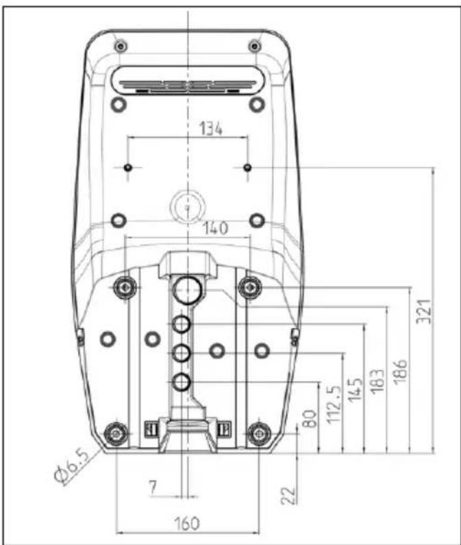
text_image
134 140 Ø6.5 7 160 22 80 112.5 14.5 18.3 186 321Fig. 10: Drilling dimensions [mm]
▶ Mark the mounting bores using the supplied drilling template or Fig. "Fig. 10: Drilling dimensions [mm]".

The provided fastening material (screws, dowels) are only suitable for installation on concrete walls, brick walls and wood walls.
▶ Drill holes in the wall with the diameter required by selected mounting material.
▶ Introduce the line into the device through a cable entry. To do this, you need to make a hole in the respective membrane.

Approx. 30 cm of cable are required for the supply line inside the device.

To prevent the ingress of rainwater, the hole in the membrane should not be larger than the cables.
text_image
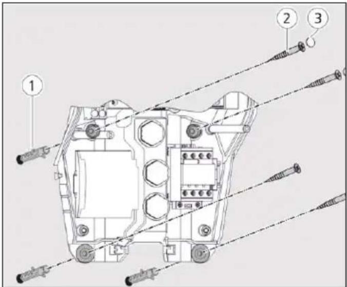
Technical diagram of a tank with numbered parts and exploded view, likely for assembly or maintenance instructions.Fig. 11: Attach to the wall
▶ Fasten the device to the wall using dowels (1), screws (2) and sealing plugs (3).
ATTENTION
Device damage due to missing sealing plugs
If the screws in the enclosure are not covered, or are not adequately covered with the provided sealing plugs, then the specified protection class is no longer ensured. Consequential damage of electronic components can occur.
▶ Cover the screws in the enclosure with the provided sealing plugs.
▶ Check the device for firm and secure attachment.
5.6 Electrical connection
5.6.1 Power supply
The device can be connected in a TN / TT network. The device can only be connected in an IT network under the following conditions:
■ Connection to a 230 / 400 V IT network is not permitted.
■ Connection to an IT network with 230 V external line voltage over a residual current circuit breaker is permissible, provided that the maximum contact voltage does not exceed 50 V AC when the first error occurs.
text_image
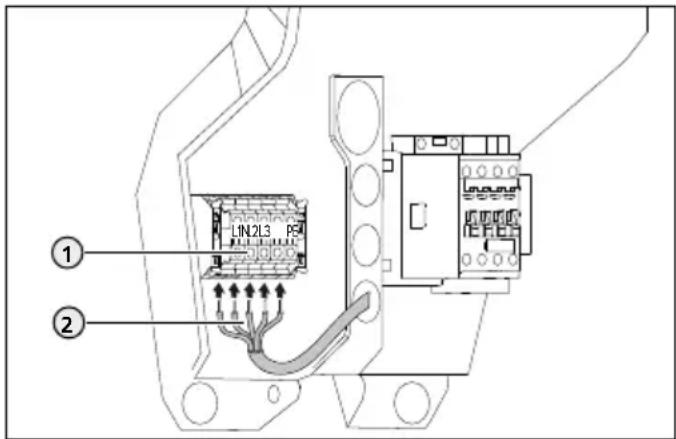
LIN2L3 ① ②Fig. 12: Power supply connection
▶ Strip the supply line.
▶ Strip conductors (2) 12 mm.
- Connect the conductors to the terminals (1) in accordance with the terminal labels.
Single phase operation: Use terminals L1, N and PE. Three-phase operation: Use terminals L1, L2, L3, N and PE.
▶ Comply with the connection data of the terminal block.
→ "4 Technical data"
When laying out the supply line, comply with the permissible bending radius.
▶ Check whether the individual cores are properly connected and that the screws are firmly tightened.
5.6.2 Shunt release
For versions Professional(+) E 7,4 / 22 only.
▶ Check whether a shunt release is legally prescribed in the country of use.
→ "2.2 Intended use"
The shunt release has been incorporated in the indoor installation.
→ "5.3.2 Providing fuse protection"
A relay for external connection of a shunt release is attached in the device.
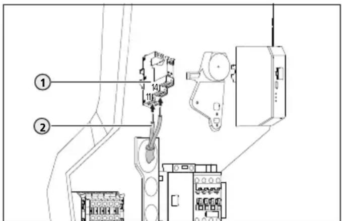
text_image
Technical diagram showing labeled components of an electrical or mechanical device with numbered parts and connection detailsFig. 13: Connection - shunt release
▶ Strip the line of the shunt release
▶ Strip the conductors (2) 8 mm.
▶ Connect the conductors on the relay (1).
To do this use terminals 11 (COM) and 14 (NO).
→ "4 Technical data"
5.7 Setting up the device for three-phase operation
Phase sequence relay
For versions Professional(+) 7,4 / 22 (PnC) only.
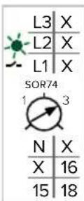
To operate the device in single-phase the potentiometer at the phase sequence relay must be changed over.
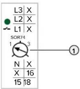
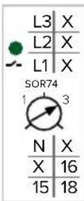
text_image
L3 X L2 X L1 X SOR74 1 3 N X X 16 15 18▶ Connect the device to single phase.
→ "5.6.1 Power supply"
▶ Adjust potentiometer (1) to position 1 using a slotted screwdriver.
| Setting Description |
| 1 Single-phase operation |
| 3 Three-phase operation |
Web interface
To operate the device on a single phase, it is necessary to change a parameter in the web interface.
→ "6 Commissioning"
▶ Navigate to the "Operator" menu and set the following parameter:
| Parameters Setting | |
| Phases connected to the ChargePoint | ▶ Select "Single-phase system". |
6 Commissioning

The activities described in this section must only be executed by a qualified electrician.
Connections
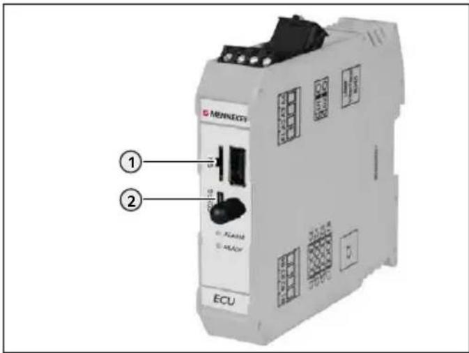
text_image
MENNECFS ① ② ECUFig. 14: Connections for the configuration on the ECU
| Pos. Use | Connection | |
| 1 | Slot for a SIM card Micro-SIM | |
| 2 | Configuration of the device | Micro-USB |
6.1 Setting up a connection to the ECU
With an existing configuration the device can be configured and status information can be called-up.
▶ Connect end device (e. g. PC, laptop, mobile phone) und ECU with the provided USB cable. To do this use the micro-USB connection (2) of the ECU.
→ "Fig. 14: Connections for the configuration on the ECU"

If the driver is not automatically installed under the Windows operating system:
▶ Navigate to "Control Panel > "Device Manager" > "Other devices".
▶ Right-click "RNDIS/Ethernet Gadget" > "Update Drive Software" > "Search for driver software on the computer" > "Select from a list of device drivers on the computer > "Network Adapter" > "Microsoft Corporation" > "NDIS-compatible remote device". The driver will be installed.
6.2 Configuring via the web interface
Configuration occurs via the web interface in an Internet browser. The web interface is password-protected.
▶ Open the Internet browser.
The web interface can be reached via http://192.168.123.123/operator.
▶ Enter password.

Password: See Set-up data sheet.
Configure the device taking into account the conditions and customer requirements.
▶ Save the configuration that has been made by clicking the "Save" button.
▶ When the configuration is concluded, click the "Save & Restart" button.

The web interface includes several possibilities to make settings that the device does not support. An overview of the device function is provided in section "3 Product description" > "Equipment Features".
Structure of the web interface
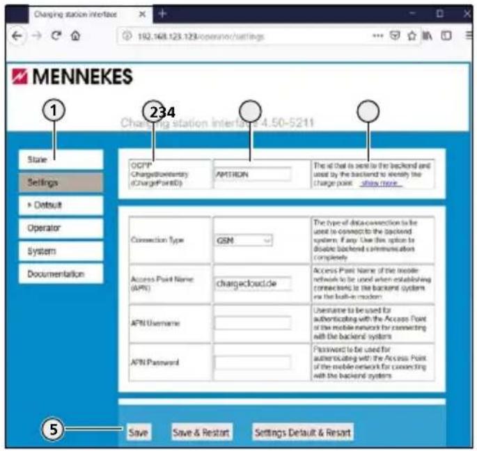
text_image
Charging station interface 192.168.123.123/operator/settings MENNEKES Charging station interface 4.50-5211 State Settings ► Default Operator System Documentation OCFP ChargePointID ChargePointID AMTRON The all that is sent to the backend and used by the backend to identify the charge point .show more... 234 Connection Type GSM Access Point Name (APR) chargecloud.de AFN Username AFN Password The type of data connection to be used to connect to the backend system. If any, Use this option to double backend communication completely. Access Point Name of the mobile network to be used when establishing connections to the backend system via the back-in modem. Username to be used for authenticating with the Access Point of the mobile network for connecting with the backend systems. Password to be used for authenticating with the Access Point of the mobile network for connecting with the backend systems Save Save & Restart Settings Default & ResortFig. 15: Structure of the web interface
- Menu
- Parameters
- Settings / status
- Comment / information
- Buttons for saving, restarting and loading the presets
The following menus are displayed in the web interface:
■ "State"
■ "Settings"
">Default"
■ "Operator"
■ "System"
■ "Documentation"
"State" menu
Here you cannot make any settings. Status information of the device is displayed, e.g.
■ Current state
■ Fault messages
■ Configuration, e.g. LED colour scheme (green / blue)
■ Backend system
Menu "Settings"
Basic settings can be made here, e.g.
■ Connection to a Backend-System
■ Maximum charging current
If necessary the presets defined in the menu "> Default" can be restored through the button "Settings Default & Restart".
Menu">Default"
This is where presets for the "Settings" menu can be defined.
Menu "Operator"
This is where all advanced settings for setting up the device can be made, e.g.
■ Connection to a Backend-System
Menu "System"
Here you cannot make any settings. Information concerning the firmware Version and the system are displayed. A firmware update can be executed here.
Menu "Documentation"
Here you cannot make any settings. The interface documentation and error messages are described.
6.2.1 Operating mode "Autostart"
The device is operated as a stand-alone solution without connection to a Backend-System. An authorisation is not required. Charging starts automatically as soon as the vehicle is plugged in.
▶ Navigate to the "Settings" menu and set the following parameters:
| Parameters Setting | |
| Connection Type | ▶ Select "No Backend". |
| Free Charging ▶ Select "On". | |
▶ When the configuration is concluded, click the "Save & Restart" button.
6.2.2 Operating mode "Local Whitelist"
The device is operated as a stand-alone solution without connection to a master Backend-System. The authorisation occurs through RFID cards and a Local Whitelist.
▶ Navigate to the "Settings" menu and set the following parameters:
| Parameters Setting | |
| Connection Type | ▶ Select "No Backend". |
| Free Charging ▶ Select "Off". | |
| If in doubt allow charging | ▶ Select "Off". |
▶ Click the "Save" button.
Teach RFID cards by holding in front of RFID card reader
▶ Navigate to the "Operator" menu and set the following parameters:
| Parameter Setting | |
| Local fixed authorization list (FLL) | ▶ Select "On". |
| FLL learning mode | ▶ Select "On".The function remains active for 5 minutes |
▶ Hold RFID cards in front of the RFID card reader one after another.
The taught RFID UIDs (Unique Identifiers) are displayed in the parameter "List of entries in FLL". A maximum of 80 RFID UIDs are displayed.
▶ When the configuration is concluded, click the "Save & Restart" button.
Teach RFID cards by entering RFID UIDs
To do this, the UIDs of the RFID cards must be known.
▶ Navigate to the "Operator" menu and set the following parameters:
| Parameter Setting | |
| Local fixed authorization list (FLL) | ▶ Select "On". |
| FLL learning mode | ▶ Select "Off". |
| List of entries in FLL | ▶ Enter RFID-UIDs.■ Syntax: UID1:UID2:UID3 ...■ Max. 80 RFID UIDs are displayed |
▶ When the configuration is concluded, click the "Save & Restart" button.
Delete RFID cards
▶ Delete all entries of the parameter "List of entries in FLL".
▶ Click the "Save & Restart" button.
▶ Teach authorized RFID cards.
▶ Click the "Save & Restart" button.
6.2.3 Operating mode "Backend-System"
The device can be connected via wireless communication or ethernet to a Backend-System. The device is operated via the Backend-System.

A connection to a Backend-System via USB or WLAN is not possible.

A micro SIM card is required for connecting via wireless communication.
▶ Insert the SIM card.
→ "6.3 Inserting the SIM card"

An internet connection via the local network is required for the connection via Ethernet. This type of connection only works in combination with OCPP-J 1.6.
▶ Navigate to the "Settings" menu and set the following parameters:
| Parameters Settings / description | |
| Connection Type | ► Select "GSM" or "Ethernet". |
| Free charging ► Select "Off". | |
| Access Point Name (APN) | Name of the access point of your mobile access |
| APN Username User name for the access point of your mobile access | |
| APN password Password for the access point of your mobile access | |
| OCPP Mode | Selection of the OCPP communication protocol |
| If "OCPP Mode" = "OCPP-S 1.5" or "OCPP-S 1.6": | |
| SOAP OCPP URL of backend (standard OCPP) | URL address of the Backend-System |
| If "OCPP Mode" = "OCPP-J 1.6": | |
| WebSocket JSON OCPP URL of Backend | WS / WSS-URL of the OCPP Backend-Systems |
| HTTP Basic Authentication password | ■ Only if "Connection type" = "Ethernet"■ An empty field prevents the HTTP Basic Authentication |
| If "OCPP Mode" = "OCPP-B 1.5" or "OCPP-B 1.6": Not relevant for the device | |
| Hostname (Binary OCPP) | Not relevant for the device. |
| Portnumber (Binary OCPP) | Not relevant for the device. |

■ Information concerning APN is provided by your mobile network operator
Information concerning OCPP and the password for HTTP Basic Authentication are provided by your Backend-System operator.
▶ Click the "Save" button.
▶ If necessary, make the appropriate advanced settings in the "Operator" menu, e.g. enter the PIN of the SIM card.
▶ When the configuration is concluded, click the "Save & Restart" button.
6.2.4 Operating mode "Networked"
Several devices are connected via ethernet. This enables use of local load management and a connection to the Backend-System can be established for all networked devices (via gateway).
Requirements:
The accessory kit for local networking of multiple devices is installed.
Multiple devices are networked.
Installation manual of the accessory kit.
6.2.5 Setting the maximum charging current
▶ Navigate to the "Settings" menu and set the following parameters:
■ "Operator Current Limit (A)"
▶ Click the "Save" button.
▶ If necessary make the appropriate extended settings in the "Operator" menu.
▶ When the configuration is concluded, click the "Save & Restart" button.
6.2.6 Advanced settings
In the "Operator" menu, extended settings are provided under "Settings", in addition to the parameters.

The web interface includes several possibilities to make settings that the device does not support. In the section "3 Product description" > "Equipment features" there is an overview of the device functions.
| Parameter Description Necessary | for ... | Remark | |
| OCPP ChargeBoxIdentity (ChargePointID) | Identification of the charging point that is sent to the Backend-System | Backend-System | The identification must be identical in the Backend-System |
Block 2: Backend-System, mobile telephony, network
| Parameter Description Necessary | for ... | Remark | |
| Connection Type Connection type to the Backend-System | Preset: "GSM" | ||
| Access Point Name (APN) Name of the access point of your mobile access | Backend-System / Mobile telephony | ■ Only relevant if "Connection Type" = "GSM" ■ Information is provided by your Backend-System operator. | |
| APN username | Username for the access point of your mobile access | ||
| APN Password | Password for the access point of your mobile access | ||
| SIMcard PIN Number PIN for unlocking the SIM card | Only if the SIM card is locked with a PIN | |
| Network selection mode Automatic or manual selection of the mobile network provider | Preset: "AUTO" | |
| Modem Access Technology Selection of the mobile telephony standard Preset: "AUTO" | ||
| Scan network operators at boot Setting that specifies whether the available mobile network providers will be displayed | Wireless communication | Preset: "Off" |
| Requested Network operator Name of the network provider that should be used in manual mode | Only relevant if "Network selection mode" = "Manual" | |
| Network operator name format Setting that specifies whether the format of the name of the network provider is alphanumeric or numeric | ||
| WAN router Access from ethernet interface to WAN interface (GSM) | Network | |
Block 3: Networking via Ethernet
| Parameter Description Necessary | for ... | Remark | |
| Mode for ethernet configuration | Mode for network configuration of charging point | Preset: “Auto (DHCP)” | |
| DHCP client hostname Host name that is sent to the DHCP server together with DHCP requests | |||
| DHCP client request retries Number of DHCP client request retries Preset: “10” | |||
| DHCP client request timeout | DHCP client request timeout (in seconds) Preset: “10” | ||
| DHCP client request delay | Wait time between DHCP client requests (in seconds) | Network | Preset: “10” |
| Static network configuration IP | IP address for static IP address configuration | ■ Only relevant if “Mode for ethernet- et configuration” = “Manual config” | |
| Static network configuration netmask | Network screen for static IP address configu- ration | ||
| Static network configuration gateway | Gateway address for static IP address config- guration | ■ The specifics for the static IP address need to be selected accor- ding to your router or switch. | |
| Static network configuration DNS | DNS server for static IP address configuration | ||
Block 4: Networking via WLAN - Networking multiple devices via WLAN is not possible.
| Parameter | Description | Necessary for ... | Remark |
| WLAN SSID | Not relevant for the device | ||
| WLAN password | Not relevant for the device | ||
| Mode for WLAN configuration | Not relevant for the device | ||
| DHCP client hostname | Not relevant for the device | ||
| DHCP client request retries | Not relevant for the device | ||
| DHCP client request timeout | Not relevant for the device | ||
DHCP client request delay Not relevant for the device
Static network configuration IP Not relevant for the device
Static network configuration netmask Not relevant for the device
Static network configuration gateway Not relevant for the device
Static network configuration DNS Not relevant for the device
EN
Block 5: USB network
| Parameter Description Necessary for ... Remark | |||
| Static USB network configuration additional IP Not relevant for the device | |||
| Static USB network configuration gateway Not relevant for the device | |||
| Static USB network configuration DNS Not relevant for the device | |||
| Parameter Description Necessary | for ... | Remark | |
| Public address of the ChargePoint | Public IP address of the ChargePoint | Backend-System | |
| Mode for selecting the public address of the ChargePoint | Mode for the selection type of the public IP addresses of the charging point | ||
| WAN router password Password for access to WAN router Network | |||
| SSL Strictness as client SSL authentication as client | Backend-System | Information will be provided by your Backend-System provider | |
| SOAP OCPP Server Port of ChargePoint (Standard OCPP) | TCP server port for the incoming connections from the Backend-System | ||
| SSL mode as server | SSL function and authentication as server | ||
| Backend connection timeout | Time until an error message is displayed, after the connection to the Backend-System has been interrupted or could not be restored | Charging system | Only relevant, if "Display backend disconnect as error" = "On" |
| Display backend disconnect as error | Setting that specifies, whether the error "Backend disconnected" will be displayed. | If this error is displayed the "Fault" LED on the device is flashing | |
Block 7: Authorization, Backend-System
| Parameter | Description | Necessary for ... | Remark |
| OCPP mode | Selection of the OCPP communication protocol | Information will be provided by your Backend-System provider | |
| SOAP OCPP URL of backend (standard OCPP) | URL address of the Backend-System | Backend-System | ■ Information will be provided by your Backend-System provider■ Only for "OCPP-S 1.5" and "OCPP-S 1.6" |
| Backend Whitelist (SOAP) | List of the IP addresses that are allowed to send requests to the device | ||
| Hostname (binary OCPP) | DNS host name or IP address of the binary OCPP proxy server for the Backend-System | Charging system | This setting input box must remain empty |
| Port number (binary OCPP) | TCP port of the proxy server for binary communication with the Backend-System | Preset: "444" | |
| WebSockets JSON OCPP URL of the Backend | WS / WSS-URL of the OCPP Backend-System | Backend-System | ■ Only for "OCPP-J 1.6". ■ ID of the charging point is automatically attached when connecting to the Backend-System |
| WebSockets keep-alive interval | WebSockets keep-alive interval (in seconds) | ■ The value "0" prevents the keep-alive interval ■ Information will be provided by your Backend-System provider | |
| HTTP Basic Authentication pass-word | Password for HTTP Basic Authentication | ■ Only if "Connection type" = "Ethernet" ■ An empty field prevents the HTTP Basic Authentication. ■ Information will be provided by your Backend-System provider | |
| Tcp Watchdog Timeout | Time until a restart will be executed, after the connection to the Backend-System has been interrupted or could not be restored | Charging system | The value "0" prevents a restart of the device |
| Enable cache Setting that specifies whether an internal cache will be used for the RFID-UID | Authori-zation | "Off": RFIDs will not be added to the internal cache | |
| List of entries in cache | Listing of the RFID-UIDs present in the internal cache | ■ Syntax: UID1:UID2:UID3 ... ■ Max. 80 RFID-UIDs | |
| Cache expiry mode The expiration date of cache entries, if the OCPP expiration date has not been specified by the Backend-System | Preset: 2038 (latest permissible time) | ||
| Cache learning mode Activates the teaching of RFID UIDs via the RFID card reader. The entries are stored in the internal cache. | The function remains active for 5 minutes | ||
| Local fixed authoriza-tion list (FLL) | Setting that specifies whether a local authorization list will be used for the RFID-UIDs | ||
| List of entries in FLL Listing of the RFID-UIDs in the local authorization list | ■ Syntax: UID1:UID2:UID3 ... ■ Max. 80 RFID UIDs are displayed | ||
| FLL learning mode Activates the teaching of RFID UIDs via the RFID card reader. The entries are stored in the local authori-zation list. | The function remains active for 5 minutes | ||
| RFID Tag letter case Setting that specifies how the RFID-UIDs will be processed by the tag management | Authorization | Information will be provided from your Backend-System operator | |
| Send Authorize for RemoteStart | Setting that specifies whether after receipt of an OCPP RemoteStart request, an OCPP authorization message will be sent to the Backend-System | Backend-System | |
| Stop Transaction Mode | Setting that specifies how the device should behave at the end of a transaction | Charging system | "Normal" unlocks and ends the transaction, if the plug on the vehicle has been unplugged (set for devices with a permanently connected charging cable) |
| Restart transaction after power loss | Setting that specifies whether a transaction will be continued after a power outage | ||
| Send informative StatusNotifications | Setting that specifies whether informative OCPP status messages will be sent to the Backend-System | Backend-System | For example, temperature reports |
| Send error StatusNotifications | Setting that specifies whether error-related OCPP status messages will be sent to the Backend-System | ||
| Send USB error StatusNotification | Not relevant for the device | ||
| Strategy for StatusNotification state transitions | Setting that specifies the conditions under which the charging point changes to the "Occupied" state | Backend-System | ■ Only for "OCPP-S 1.5" ■ "Occupied on Charging": Occupied when an authorization is present and a charging cable is plugged in ■ "Occupied on Authorized/Plugged": Occupied when the charging point is authorized or a charging cable / vehicle is connected |
| Preparing until state C (OCPP 1.6) | Setting that specifies the conditions under which the charging point changes to the "Charging" state | ■ Only for "OCPP-S 1.6" and "OCPP-J 1.6" ■ "On": Charging when the vehicle is in C status ■ "Off": Charging when the vehicle is in status B or C | |
| Allow long get configuration keys | Setting that specifies whether OCPP keys are allowed to contain more than 500 characters | ||
EN
Block 8: Charging settings
| Parameter Description Necessary for ... Remark | |||
| Free charging Charging without authorization. Charging process begins as soon as a vehicle is plugged in | |||
| Free charging mode Setting the OCPP behavior Only when "Free | Authorization | charging" = "On" | |
| Rfid Tag for Free Charging with OCPP Full, fixed rfid modes | RFID UID for the mode “Full fixed Rfid” | ||
| If in doubt allow charging Emergency charging if no Backend-System is connected | |||
Block 9: Charging current
| Parameter Description Necessary for ... Remark | ||
| Operator Current Limit (A) Maximum charging current Charging sys- | tem |
Block 10: Dynamic load management (DLM)
| Parameter Description Necessary | for ... | Remark | |
| Dynamic Load Management | Used to set the charge point function for load management in a DLM network | ||
| DLM Network Id Setting that specifies which DLM network ID the charge point is assigned to | Format: Any number between 0 and 255 | ||
| DLM Master IP and port | IP address of the DLM master that controls the charging point. The port can also be specified | ||
| Disable Discovery Broadcasting | Setting that specifies whether Discovery Broadcasting is disabled on the DLM-Master | Charging system | For the assignment of static IP addresses, this parameter must be set to "On" |
| DLM Algorithm Sample Rate | Duration required to determine the algorithm | ||
| Allow EV Wakeup Setting that species whether to continue to provide charging current after charging the vehicle | |||
| EVSE Sub-Distribution Limit (L1/L2/L3) [A] | Maximum mains current available for load management | e.g. rated fuse current in the power supply cable | |
| Operator EVSE Sub-Distribution Limit (L1/L2/L3) [A] | Upper current limit for load management. This value can be changed during operation (e.g. temporarily from Backend-System) | This value is smaller than or equals the value for “EVSE Sub-Distribution Limit” | |
| External Input 1 Config | Not relevant for the device | ||
| Ext. Input 1 Current Offset (L1/L2/L3) [A] | Not relevant for the device | ||
| External Input 2 Config | Not relevant for the device | ||
| Ext. Input 2 Current Offset (L1/L2/L3) [A] | Not relevant for the device | ||
| External Meter Support | This setting specifies whether an external energy meter is connected for additional consumers | The external energy meter has to be connected to the router or switch via an ethernet cable. | |
| Main Distribution Limit (L1/L2/L3) [A] | Upper current limit for load management and for additional consumers | ■ Only if “External Meter Support” = “On”■ This value is higher than the value for “EVSE Sub-Distribution Limit” | |
| External Load Headroom (L1/L2/L3) [A] | Safety margin for volatile consumers (in A). Subtract this value from the value in the parameter "Main Distribution Limit (L1/L2/L3) [A]" to obtain the maximum upper current limit of the charging infrastructure | Only if “External Meter Support” = “On” | |
| External Load Fallback (L1/L2/L3) [A] | Upper current limit if no external energy meter is connected | Only if “External Meter Support” = “On” | |
| External Meter Location | This setting specifies how the external energy meter is connected | Charging system | ■ Only if “External Meter Support” = “On”■ “Including EVSE Sub-Distribution”: Used to detect charging points and additional consumers■ “Excluding EVSE Sub-Distribution”: Used to detect charging points only |
| External Load Averaging Length [sec] | Setting that specifies the duration (in seconds) to be used for determining the average of the external energy meter | ■ Only if “External Meter Support” = “On”■ Preset: “5” | |
| Current Imbalance Prevention | This setting specifies whether current imbalances should be limited. The individual phase currents are limited so that the value difference between the individual phase currents does not exceed the value for “Current Imbalance Limit” | ||
| Current Imbalance Limit | Maximum value difference between individual phase currents (in A) | Only if “Current Imbalance Prevention” = “On” | |
| Minimum Current Limit [A] | Lower current limit which is not exceeded when charging | ||
| Disconnected Limit [A] | Current limit if no DLM network is connected | ||
| Clear persistent DLM slave DB | Deletes the database of the known DLM-Satellite The database must be deleted when a DLM-Satellite is decommissioned | ||
Block 11: Energy meter
| Parameter Description Necessary | for ... | Remark | |
| Reset Meter Value Behaviour (S0 and internal meter) | Reset of the energy meter at each charging process | Backend-System | |
| Send signed meter values Not relevant for the device | |||
| The format of signed meter values | Not relevant for the device | ||
| Send the meter's public key to HTB backend | Not relevant for the device | ||
| Data transfer for Tariff And Total Usage | Setting that specifies whether information concerning the tariff and energy consumption should be displayed | Information will be provided by your Backend-System provider | |
| Meter values sampled data (OCPP) | List of parameters sent by the energy meter during a charging process via OCPP | ||
| Meter Value Sample Interval (OCPP) | Interval (in seconds) for the transmission of values for "Meter values sampled data (OCPP)" | Backend-System | |
| Meter values aligned data (OCPP) | List of parameters sent by the energy meter via OCPP, independent of the charging process | ||
| Clock aligned data interval (OCPP) | Interval (in seconds) for the transmission of values for "Meter values aligned data (OCPP)" | ||
| Meter configuration (Second) External energy meter selection for additional consumers | Only if “External Meter Support” = "On" | ||
| IP address of second meter IP address of the external energy meter | Charging system | ||
| Port number of Second Meter Port number of the external energy meter | Preset: “502” | ||
| Pulses per kWh (Second S0 meter) | Not relevant for the device | ||
Block 12: Other
| Parameter Description Necessary | for ... | Remark | |
| HLC 15118 configuration Enables communication in accordance with ISO 15118 | ISO 15118 | For Professional+ 7.4 / 22 PnC versi-ons only | |
| Use of SA Schedule in 15118 HLC | Allows the forwarding of load profiles to the vehicle which are set by the operator via the Smart Charging Profile (Secondary Actor) for the charging point. | ||
| Extra HLC 15118 logging Used to activate the recording of the input and output streams of ISO 15118 communication. The log is stored in the hlc_log.csv file | |||
| Power source voltage Rated voltage between phase conductor and neutral con-ductor | |||
| Phases connected to the ChargePoint | Number of phases connected on the device | ||
| Phase rotation of the ChargePoint | Direction of rotation of the phases L1, L2 and L3 Only relevaCharging system | for three-phase operation | |
| Tilt detection Setting of tilt detection | |||
| Randomise charging after power loss | Random delay after power failure to avoid peak currents | ||
| Language of Display Not relevant for the device | |||
| UTC time for housekee-ping reboot | Time for restart of the device | A restart will be performed every 30 days | |
| Vehicle connection timeout | Time that is allowed to elapse between an authorization and connection of the vehicle to the device, in order to start a charging process | Charging system | |
| Lock Actuator only if authorized | Locking of the charging plug only after authorization | ||
| Permanently locked cable | Permanent locking of the charging plug | ||
| Temperature Report Delta | Temperature change (in °C), that is necessary in order to send a temperature report to the Backend-System | Backend-System | |
| RCMB Delta Differential current change (in 0.1 mA) that is necessary for sending an OCPP status notification to the Backend-System | |||
| Energy management from second meter | Energy management using an external meter | ||
| Current limit for energy management from second meter | Current limit (in A) for energy management using an exter-nal meter | Charging system | |
| Energy management from external input | External management using an external switching contact | ||
| Current limit for energy management from external input | Current limit (in A) for energy management using an exter-nal switching contact | ||
| Operator Password Password for the web interface | |||
| USB Installer Password Not relevant for the device | |||
| State page password protection | Activates password protection for the "State" page | ||
| Led colour scheme Colour scheme of the LED information panel | Charging system | ||
| HMI beep Activates the acoustic signal transducer | |||
| Log Level Scope of the data logger | |||
6.3 Inserting the SIM card
For versions Professional+ (E) 7,4 / 22 (PnC) only.

TENTION
Damage to components
Damage to components or the charging station from electrostatic discharging.
▶ Touch an earthed metal part before inserting the SIM card.
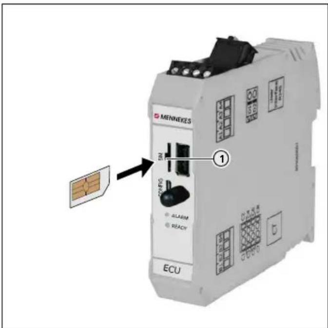
text_image
MENVERKES SN 1 ALARM READY ECUFig. 16: Inserting the SIM card
▶ Insert SIM card in the micro-SIM slot (1).
6.4 Switching on the device
ANGER
Electric shock hazard when devices are damaged
If a damaged device is used people can be seriously injured or killed through an electric shock.
▶ Do not use the device if it is damaged.
▶ Mark the damaged device to ensure that no one continues using it.
▶ Eliminate the damage immediately.
▶ Take the device out of service if necessary.
Precondition:
■ Device is installed correctly.
■ Device is in a proper condition.
■ For versions Professional(+) E 7,4 / 22 only:
The necessary fusing devices (residual current device, circuit breaker, possibly a shunt release) are incorporated in the indoor installation, and are functional and switched on.
→ "5.3.2 Providing fuse protection"
■ During the initial setting-up process, the device was inspected in accordance with IEC 60364-6 and the applicable national regulations (e.g. in Germany: DIN VDE 0100-600).
→ "6.6 Checking the device"
▶ Switch on the power supply and check.
→ "6.5 Monitoring the power supply"
VED "Standby" is illuminated on the LED information panel.
6.5 Monitoring the power supply
For versions Professional(+) 7,4 / 22 (PnC) only.
The device is monitored by a phase sequence relay. It checks the three phase (L1, L2, L3) and the neutral conductor (N) of the power supply for correct phase sequence, phase failure or undervoltage.
Operating status display
Three phases, clockwise field of rotation:
▶ Using terminals L1, L2, L3, N, PE.
▶ Setting relay potentiometer to 3.
The green LED is lit.
Three phases, anti-clockwise field of rotation:
▶ Using terminals L1, L2, L3, N, PE.
▶ Setting relay potentiometer to 3.
The green LED is flashing.

One phase:
▶ Using terminals L1, N, PE.
▶ Setting relay potentiometer to 1.
The green LED is lit.
The evaluation of the relay potentiometer occurs only once, after applying the supply voltage.
6.6 Checking the device
Test according to IEC 60364-6 and the applicable national regulations (e.g. in Germany: DIN VDE 0100-600)
Prior to the initial commissioning, execute a test of the device in accordance with IEC 60364-6 and the applicable national regulations (e.g. DIN VDE 0100-600 in Germany). The test can be carried out in connection with the MENNEKES test box and a standard-compliant test equipment. The MENNEKES test box simulates vehicle communication. Test boxes are available as accessories from MENNEKES.
▶ Perform a standard test before releasing the device.
Operating instructions of the test box.
6.7 Closing the device
ATTENTION
Device damage due to crushed components or cables If components or cables are crushed when closing the device, damage and malfunctions can occur.
▶ When closing the device ensure that components or cables are not crushed.
▶ If necessary fix components or cables in place.
text_image
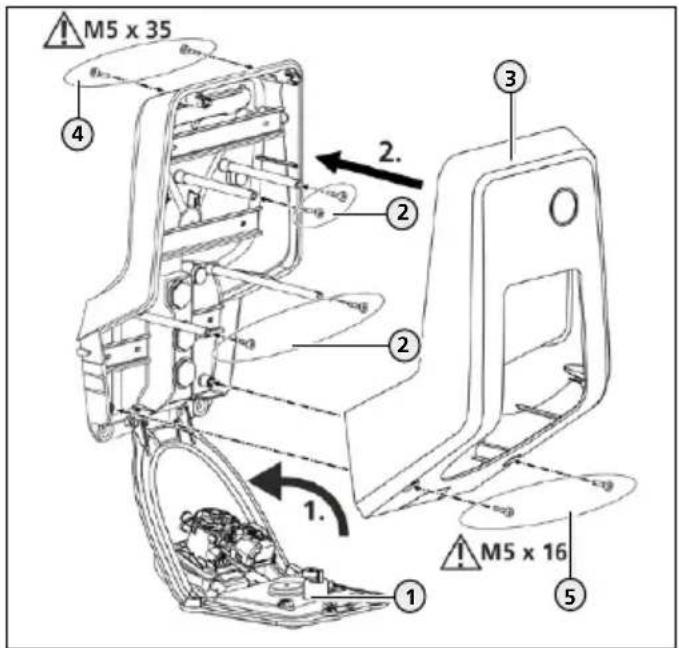
M5 x 35 4 2. 2 2 1. 1 M5 x 16 3 5Fig. 17: Closing the device
▶ Lift the front panel (1) upwards and secure it with the screws (2).
▶ Fit the upper enclosure part (3) and secure it with the screws (4) and (5). Use supplied shortened Allen key.
| Screw Torque | |
| (2) 0.5 Nm | |
| (4) 1.2 Nm | |
| (5) 1.2 Nm |
7 Operation
7.1 Authorization
Depending on the configuration, using the device may require prior authorisation The following possibilities exist:
■ No authorisation is required. All users can charge.
■ Authorisation through RFID.
■ All users with an RFID card can charge.
■ All users whose RFID card is activated can charge.
■ Authorisation through Backend-System.
■ Authorisation is dependent on a Backend-System, for example with an RFID card, a smartphone app or ad hoc (e.g. direct payment).
■ For version Professional+ 7,4 / 22 PnC only: Authorisation by communication between device and vehicle according to ISO 15118.
Requirement: support your vehicle and backend system (ISO 15118).
The "Standby" symbol lights up on the LED information panel.
▶ Authorising depending on the configuration:
▶ Authorisation through RFID: Hold the RFID card in front of the RFID card reader.
▶ Authorisation through Backend-System: Follow the instructions for the respective Backend-System.
▶ Authorisation according to ISO 15118: Connect the charging cable to the vehicle and, if necessary, to the device.
▶ Comply with the instructions on the device (e.g. scan QR code).
The data are checked. The "Wait time" symbol lights up on the LED information panel.
The authorisation was successful. The charging process can now be started.
i
If charging does not start within the release time, the authorisation is reset, the charging sockets are locked and the device switches to "Standby" mode. A new authorisation is required.
If the authorisation process is not completed, the following problems may exist:
| Problem Solution | |
| Unknown customer number. | ► Create customer in backend system. |
| Your account has not been activated. | ► Check settings in the backend system. ► Make sure that the customer activated in the backend system. |
| No communication between the device and the Backend-System. | ► Repeat the authorisation process. |
7.2 Charging the vehicle
WARNING
Risk of injury from using unsuitable aids
Use of adaptor plugs, extensions, or additional charging cables in connection with the device can result in electric shock or cable fire.
▶ Use only the charging cable intended for the vehicle and the device.
▶ Do not use adaptor plugs, extensions, or additional charging cables to charge the vehicle.
natural_image
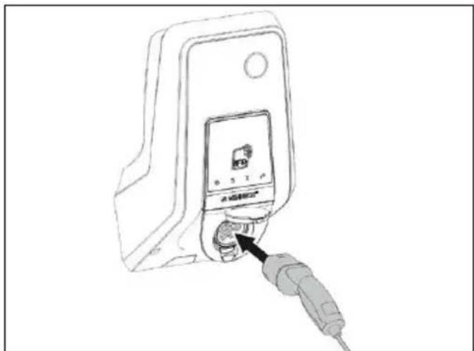
Line drawing of a device with a plug inserted into the socket (no text or symbols)Fig. 18: Charging the vehicle (example)
The authorisation process is complete.
▶ Ensure that the vehicle and the charging cable are suitable for Mode 3 charging.
▶ Unroll the charging cable completely.
▶ Connect the charging cable to the vehicle.
For the variant, charging socket with hinged lid:
▶ Flip up the hinged lid.
▶ Completely plug the charging plug into the charging socket on the device.
For the variant, charging socket with shutter:
▶ Insert the plug into the charging socket on the device.
The contour of the grey ring indicates the orientation of the plug.
▶ Turn charging plug 60° counterclockwise to open the shutter.
▶ After opening the shutter, insert the charging plug completely into the charging socket.
The charging plug is automatically locked and the charging process is started.
If charging does not start, the following problem may exist:
Problem Solution
Interlocking of the charging plug is not possible.
▶ Check charging socket for foreign objects.
▶ Check charging cable and replace if necessary.
Terminating the charging process
ATTENTION
Damage to the charging cable
Tensile stress of the charging cable may cause cable breaks and other damage.
▶ Only pull the charging cable directly from the socket outlet.
▶ End the charging process on the vehicle or by holding the RFID card in front of the RFID card reader.
▶ Pull the charging cable out of the charging socket on the plug.
▶ Fit the protective cap onto the charging cable.
▶ Hang or store the charging cable kink-free.
Charging cable cannot be unplugged
If the charging plug cannot be removed, e.g. after a power failure, the charging plug could not be unlocked in the device. The charging plug cannot be removed and must be unlocked manually.
▶ Have the charging plug unlocked by a qualified electrician via the emergency unlock function.
→ "9.3 Unlock the charging plug"
7.3 Multifunction button
For versions Professional(+) 7,4 / 22 (PnC) only.
7.3.1 Restarting residual current device and circuit breaker
text_image
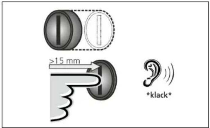
I >15 mm *klack* *klack*Fig. 19: Restarting residual current device and circuit breaker
▶ Press the multifunction button up to the end position (> 15 mm).
Residual current device and miniature circuit breaker are switched on again.
8 Maintenance
7.3.2 Checking the residual current device
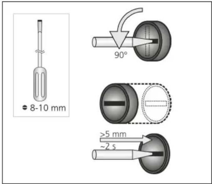
text_image
8-10 mm 90° >5 mm ~2 sFig. 20: Checking the residual current device
▶ Insert a flat screwdriver with a blade width of 8 to 10 mm into the slot of the multifunction button.
▶ Turn the multifunction button 90° counterclockwise.
▶ Press the multifunction button for about two seconds (>5mm).
Is the residual current device functional:
The residual current device triggers.
The fault indicator on the LED info field flashes red.
▶ Switch the residual current device on again.
→ "7.3.1 Restarting residual current device and circuit breaker"
8.1 Servicing
!ANGER
Electric shock hazard when devices are damaged
If a damaged device is used people can be seriously injured or killed through an electric shock.
▶ Do not use the device if it is damaged.
▶ Mark the damaged device to ensure that no one continues using it.
▶ Have a qualified electrician rectify the damage immediately.
▶ Have an electrician take the device out of service if necessary.
Regular control and maintenance tasks support the safe and error-free operation of the device and contribute to increasing the service life.
This allows early detection of possible error sources and prevents hazards. If it is determined that the device is damaged, the damage must be rectified immediately by a qualified electrician.
▶ Check the device daily, i.e. at each charging, for operational readiness and external damage.
Examples of damage:
■ Defective housing / front panel (e.g. severe deformations, cracks, breaks)
■ Defective or missing components (e.g. protective elements, hinged lid)
■ Illegible or missing safety labels.

A maintenance contract with a responsible service partner guarantees regular tests.
Maintenance intervals

The tasks described below may only be carried out by a qualified electrician.
Select the maintenance intervals with due consideration of the following aspects:
■ Age and condition of the device
■ Environmental influences
■ Mechanical stress
■ Last test reports
Perform maintenance at least in the following intervals:
Component Maintenance work
| Every 6 months | |
| Electrical switching and safety devices | Check residual current device, line circuit breaker etc. for apparent defects.Check residual current device for damage. |
| Housing interior | Ensure that the device is clean. Clean if necessary. |
| Housing exterior | Check device for defects and damage.Ensure that the device is clean. Clean if necessary.→ "8.2 Cleaning" |
| Charging cable (for the variant with permanently connected charging cable) | Check charging cable for damage (e.g. kinks, cracks).Repetition of measurements and tests in accordance with IEC 60364-6 and the applicable national regulations (e.g. in Germany: DIN VDE 0701/702). |
| LED Info bar Check LED information panel for function and readability. | |
Component Maintenance work
Every 6 months
| Charging socket(for variant with charging socket) | Check hinged lid or shutter for function and ease of movement. |
| Check the contacts of the charging socket for contamination and foreign objects. If necessary clean charging socket and remove foreign objects. |
Component Maintenance work
| Annually | |
| Connection terminals | Check the terminals of the supply line. If necessary retighten terminals |
| Device Repetition | of measurements and tests according to IEC 60364-6 and the applicable national regulations (e.g. in Germany: DIN VDE 0105-100). |
▶ Eliminate damage to the device according to regulations.
▶ Document maintenance sufficiently.
▶ If necessary, request a maintenance protocol from MENNEKES.
→ "1.1 Service"
8.2 Cleaning
ANGER
Risk of fatalities due to electric shock
The device contains electrical components that carry high voltage. Improper handling of the opened housing, especially in connection with moisture, will cause severe injury to persons due to electric shock.
▶ Clean only the outside of the device.
▶ Keep the device and protection systems closed.
ATTENTION
Material damage due to incorrect cleaning
Incorrect cleaning can cause damage to the housing or components.
▶ Do not use running water and ensure that water cannot reach live parts.
▶ Do not use high-pressure cleaning devices.
▶ Only use tools (e.g. brushes, cleaning agents) that are suitable for plastic surfaces.
▶ Do not use aggressive cleaning agents or chemicals.
The device can be cleaned with a dry or damp cloth, depending on application conditions and soiling. The cleaning is carried out exclusively from the outside.
Procedure:
▶ First remove coarse dust and contamination with a hand brush with soft bristles.
▶ If necessary, moisten a clean cloth that is suitable for plastic surfaces with water and thoroughly wipe off the device.
▶ Only clean the charging cable when it is unplugged.
8.3 Firmware Update
The firmware is subject to ongoing further development; this means that after some time new firmware updates are available.
You can obtain the current software from MENNEKES on request.
→ "1.1 Service"
9 Remedy
If a fault occurs the "Fault" symbol lights up or flashes on the LED information panel. The device cannot be used as long as the fault has not been rectified.
Possible faults:
■ Wrong or defective charging cable.
■ For versions Professional(+) 7,4 / 22 (PnC) only: Residual current device or circuit breaker has triggered.
To correct the fault, observe the following sequence:
▶ Terminate the charging process and disconnect the charging cable.
▶ Check whether the charging cable is suitable.
▶ Plug the charging cable back in and start the charging process.
For versions Professional(+) 7,4 / 22 (PnC) only: Restart residual current device or circuit breaker.
→ "7.3.1 Restarting residual current device and circuit breaker"

If the fault could not be corrected, contact your responsible service partner.
→ "1.1 Service"
9.1 Fault messages

The tasks described below may only be carried out by a qualified electrician.
The error message can be viewed via the web interface.
A network connection is established.
→ "6.1 Setting up a connection to the ECU"
Reading out an error message
In the web browser, at http://192.168.123.123/operator, navigate to "State".
▶ In the "Errors list" row, the error message is displayed in the second column.
Example:
| ... ... ... | ||
| Errors list Residual current detected via sensor | ... | |
| ... ... ... | ||
Finding solution approaches for the error message
▶ Navigate to "Documentation" > "Errors Documentation". In the second column, "Error activation message", all error messages are listed.
▶ Find the current error message in the column, Error activation message" and follow the solution approaches in the column, "Corrective actions".
Example:
| ... Error activation message | ... ... Corrective actions |
| ... ... ... | |
| ... Residual current detected via sensor | ... ... The safety mechanism is reset to its original state every time the plug is removed and automatically after 15 minutes if the plug is not removed. If problem persists check yellow current transformer and its connection. |
| ... ... ... ... |

Several Backend-Systems provide additional assistance for troubleshooting.
9.2 Spare parts
If replacement or accessory parts are necessary for troubleshooting, these must first be checked to ensure the same design.
▶ Use only spare parts and accessories that are manufactured and/or approved by MENNEKES.
→ "1.1 Service"
9.3 Unlock the charging plug

The tasks described below may only be carried out by a qualified electrician.
If the unlock function fails, the situation can occur that the charging plug is mechanically interlocked by the actuator. The charging plug cannot be removed and must be unlocked manually.
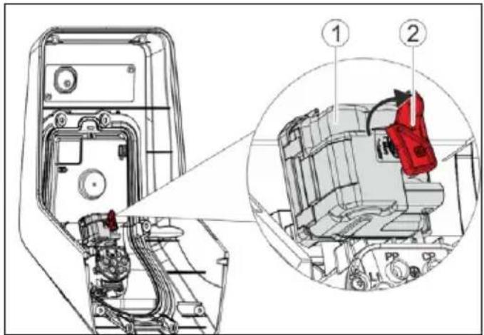
text_image
Technical diagram of a mechanical assembly with labeled parts, showing internal components and a zoomed-in detail view.Fig. 21: Unlocking the charging plug
▶ Open the device.
→ "5.4 Opening the device"
▶ Fit the red lever (2) on the square shaft of the actuator (1). The red lever is attached with a cable tie close to the actuator.
▶ Turn the red lever on the actuator 90° clockwise.
▶ Unplug the charging plug
Remove the red lever and fasten it close to the actuator with a cable tie.
▶ Close the device.
→ "6.7 Closing the device"
10 Taking out of service and dismantling

The tasks described in this section may only be carried out by a qualified electrician.
Taking the device out of service
▶ Open the device.
→ "5.4 Opening the device"
▶ Disconnect the supply line.
▶ If necessary, disconnect the line of the shunt release.
Dismantling the device
▶ Take the device out of service.
▶ Remove plugs and screws.
▶ Detach the device from the wall.
▶ Route lines out of the enclosure.
▶ Close the device.
→ "6.7 Closing the device"
11 Storage
Proper storage can positively affect and maintain the operability of the device.
▶ Clean the device before storing.
- Store the device in a clean and dry place in its original or other suitable packaging.
▶ Observe permissible storage conditions.
Permissible storage conditions
| Storage temperature -25°C... | + 40°C |
| Average temperature over 24 hours | < 35 °C |
| Relative humidity max. 95 % | (non-condensing) |
12 Disposal

Discard the device and packaging according to regulations at the end of its service life. Observe the national regulations for disposal and environmental protection applicable in the country of use. Old devices and batteries must not be disposed of with household waste.
▶ Dispose of packaging material in designated collection containers.
▶ Dispose of old devices and batteries via your dealer.
13 Accessories
Accessories, such as protective roofs or charging cables, are available on our website under "Accessories".
https://www.chargeupyourday.com/

14 Glossary
| Term Explanation | |
| Backend system | Infrastructure for controlling the charging stations and the management of personal access data. |
| ECU Electronic Control Unit | |
| Unit for control and communication | |
| MiD Measuring Instruments Directive | |
| Energy meter | |
| Mode 3(IEC 61851) | Charging mode for vehicles with communication interface on charging couplers type 2. |
| RFID Authorisation option via RFID card to devices. | |
| Type 2(IEC 62196-2) | Single- and three-phase charging couplers with identical plug geometry for charging powers ranging from 3.7 to 44 kW AC. |
Índice
1 Acerca de este documento ....2
6.2.2 Modo operativo "Whitelist local"......19
6.2.3 Modo operativo "Backend-System"....20
6.2.4 Modo operativo "Interconectado"......21
8.3 Firmware Update....37
9 Solución de problemas....37
https://www.chargeupyourday.com/

https://www.chargeupyourday.com/faqs/

1.2 Advertencias
text_image
Diagram of a device with labeled parts including an RFID scanner, memory card, and various electronic components.text_image
Diagram of a device control panel with numbered labels pointing to key componentstext_image
Technical diagram of a remote control device with numbered components for identificationtext_image
Technical diagram of an electronic device rear panel with numbered components for identificationFig. 5: Vista interior (ejemplo: variante Professional+ E 7,4 / 22
natural_image
White medical device with blue cable and a small screen, placed on a plain surface (no visible text or symbols)natural_image
Person interacting with a white Männikre's charging station, no visible text or symbols on device or backgroundThe Ground Truth image displays a single, solid horizontal line. According to Rule 2 (UNDERSCORE & LINE RULES), this is a stylistic or background line, not a placeholder underscore. Therefore, the OCR result must ignore it and output nothing or only meaningful text. The provided OCR content is "____", which consists of four underscores. This is an incorrect interpretation of the line as a placeholder, violating the rule that stylistic lines must be ignored. The OCR has hallucinated placeholder underscores where none should exist in the GT. Hence, the OCR result is inconsistent with the Ground Truth.
En espera
natural_image
White medical device with blue cable and connector, no visible text or symbols
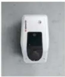
natural_image
White remote control device with black display and circular ports (no visible text or symbols)
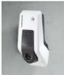
natural_image
White handheld device with black buttons and a small vent, isolated on a plain background (no visible text or symbols)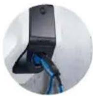
https://www.chargeupyourday.com/

4 Datos técnicos
text_image
Technical diagram of a mechanical assembly with numbered components and directional arrows indicating motion or flow.text_image
Technical diagram of a vehicle's internal components with numbered parts labeled 1, 2, and 3.text_image
Technical diagram showing labeled components of an electrical or mechanical device with numbered parts and connection detailstext_image
L3 X L2 X L1 X SOR74 1 3 N X X 16 15 18text_image
MENNECFS ① ② ECUtext_image
Charging station interface 192.168.123.123/operator/settings MENNEKES Charging station interface 4.50-5211 State Settings ► Default Operator System Documentation OCFP ChargePointID ChargePointID AMTRON The at that is sent to the backend and used by the backend to verify the charge point - show more. 234 Connection Type GSM The type of data connection to be used to connect to the backend system. If any, Use this option to double backend communication completely Access Point Name (APR) chargecloudide Access Point Name of the mobile network to be used when establishing connections to the backend system on the back-in mode: APR Username Username to be used for authenticating with the Access Point of the mobile network for connecting with the backend system APR Password Password to be used for authenticating with the Access Point of the mobile network for connecting with the backend system Save Save & Restart Settings Default & ResortFig. 15: Estructura de la interfaz web
6.2.2 Modo operativo "Whitelist local"
natural_image
Line drawing of a device with a plug inserted into a terminal block (no text or symbols visible)text_image
I >15 mm *klack*| ... Error activation message | ... ... Corrective actions |
| ... ... ... | |
| ... Residual current detected via sensor | ... ... The saftey mechanism is reset to its original state every time the plug is removed and automatically after 15 minutes if the plug is not removed. If problem persists check yellow current transformer and its connection. |
| ... ... ... ... |

text_image
Technical diagram of a mechanical assembly with labeled parts, showing internal components and a zoomed-in detail view.https://www.chargeupyourday.com/

14 Glosario
https://www.chargeupyourday.com/faqs/

1.2 Avertissements
Avertissement, dommages corporels
ANGER
2.4.1 Qualifications
text_image
Diagram of a device with labeled parts including an RFID scanner, memory card, and various electronic components.text_image
Diagram of a device control panel with numbered labels pointing to key componentstext_image
Technical diagram of a remote control device with numbered components for identificationtext_image
Technical diagram of an electronic device rear panel with numbered components for identificationnatural_image
White medical device with blue cable and connector, no visible text or symbolsFig. 6: Suspension du câble
natural_image
Person interacting with a white MENNERS® medical device, no visible text or symbols on the device itselfnatural_image
White medical device with blue cable and connector, no visible text or symbols
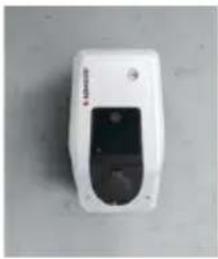
natural_image
White remote control device with black display and circular ports (no visible text or symbols)
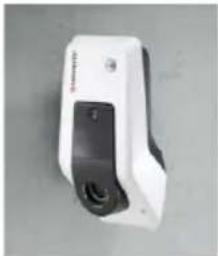
natural_image
White and black handheld device with a black button and a small screen (no visible text or symbols)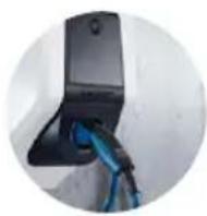
https://www.chargeupyourday.com/

Montage mural – Installation apparente
text_image
Technical diagram of a mechanical assembly with numbered components and directional arrows indicating motion or movement.text_image
Technical diagram of a mechanical assembly with numbered components and exploded viewFig. 11: Fixation murale
text_image
Technical diagram showing labeled components of an electrical or mechanical device with numbered parts and connection detailstext_image
L3 X L2 X L1 X SOR74 1 3 N X X 16 15 18text_image
Charging station interface 192.168.123.123/operon settings MENNEKES Charging station interface 4.50-5211 State Settings ► Default Operator System Documentation OCFP ChargePointID ChargePointID APTRON The at that is sent to the backend and used by the backend to identify the charge point - show more... Connection Type GSM Access Point Name (APR) chargecloudie Access Point Name of the mobile network to be used when establishing connecting to the backend system via the base-in modem APR Username Username to be used for authenticating with the Access Point of the mobile network for connecting with the backend systems APR Password Password to be used for authenticating with the Access Point of the mobile network for connecting with the backend systems Save Save & Restart Settings Default & Resortnatural_image
Line drawing of a device with a plug inserted into the socket (no text or symbols)text_image
I >15 mm *klack*| ... Error activation message | ... ... Corrective actions |
| ... ... ... ... | |
| ... Residual current detected via sensor | ... ... The safety mechanism is reset to its original state every time the plug is removed and automatically after 15 minutes if the plug is not removed. If problem persists check yellow current transformer and its connection. |
| ... ... ... ... ... |

text_image
Technical diagram of a mechanical assembly with labeled parts and a magnified inset showing component details.https://www.chargeupyourday.com/

14 Glossaire
https://www.chargeupyourday.com/
https://www.chargeupyourday.com/faqs/

text_image
Diagram of a device with labeled parts including an RFID scanner, memory card, and storage compartmentstext_image
Diagram of a mobile phone control panel with numbered labels pointing to ports and indicatorsFig. 3: Vista frontale (esempio)
text_image
Technical diagram of a remote control device with numbered components for identificationFig. 4: Vista posteriore
text_image
Technical diagram of an electronic device rear panel with numbered components for identificationFig. 5: Vista interna (esempio: variante Professional+ E 7,4 / 22)
natural_image
White medical device with blue cable and a small black screen, placed on a plain surface (no visible text or symbols)natural_image
Person interacting with a MINNES electric shock absorber device (no visible text or symbols on device body)■ "Whitelist locale"
natural_image
White medical device with blue cable and connector, no visible text or symbols
natural_image
White handheld device with a black screen and circular lens, placed on a plain surface (no visible text or symbols)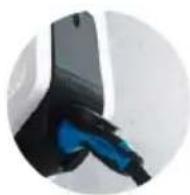
natural_image
White handheld device with black buttons and a small screen, isolated on a plain background (no visible text or symbols)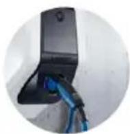
https://www.chargeupyourday.com/

4 Dati tecnici
text_image
Technical diagram of a mechanical assembly with numbered components and directional arrows indicating motion or movement.text_image
Technical diagram of a tank with numbered parts and exploded view, likely for assembly or maintenance instructions.text_image
Technical diagram showing labeled components of an electrical or mechanical device with numbered parts and directional arrowstext_image
L3 X L2 X L1 X SOR74 1 3 N X X 16 15 18text_image
Charging station interface 192.168.123.123/operator/settings MENNEKES Charging station interface 4.50-5211 State Settings ► Default Operator System Documentation OCFP ChargePointID ChargePointID APTRION The at that is sent to the backend and used by the backend to verify the charge point - show more. 234 Connection Type GSM The type of data connection to be used to connect to the backend system, if any. Use this option to disable backend communications completely. Access Point Name (API) chargecloudie Access Point Name of the mobile network to be used when establishing connectors to the backend system are the fault-in modem. APNI Username Username to be used for authenticating with the Access Point of the mobile network for connecting with the backend systems. APNI Password Password to be used for authenticating with the Access Point of the mobile network for connecting with the backend systems. Save Save & Restart Settings Default & Resortnatural_image
Line drawing of a device with an attached plug and a control panel (no text or symbols)text_image
I >15 mm *klack*| ... Error activation message | ... | Corrective actions |
| ... ... ... ... | ||
| ... Residual current detected via sensor | ... | The saftey mechanism is reset to its original state every time the plug is removed and automatically after 15 minutes if the plug is not removed. If problem persists check yellow current transformer and its connection. |
| ... ... ... ... ... |

text_image
Technical diagram of a mechanical assembly with labeled parts, showing internal components and a zoomed-in detail view.https://www.chargeupyourday.com/

14 Glossario
5.4 Apparaat openen....14
https://www.chargeupyourday.com/faqs/

1.2 Waarschuwingen
text_image
Diagram of a device with labeled parts including an RFID device, memory, and various electronic components.→ "3.9 Apparaatvarianten"
Vooraanzicht
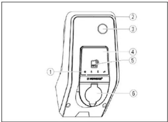
text_image
Diagram of a mobile phone control panel with numbered labels pointing to ports and indicators→ "3.9 Apparaatvarianten"
Achteraanzicht

text_image
Technical diagram of a remote control device with numbered components for identificationtext_image
Technical diagram of an electronic device rear panel with numbered components for identification→ "3.9 Apparaatvarianten"
3.4 Kabelophanging
natural_image
White medical device with blue cable and connector, no visible text or symbolsAfb. 6: Kabelophanging
3.5 Energiemeter
natural_image
Person interacting with a white MINIKES® medical device (no visible text or symbols on device body)natural_image
White medical device with black cover and blue cord, connected by a blue cable (no visible text or symbols)
natural_image
White handheld device with a black lid and circular button, placed on a plain surface (no visible text or symbols)
natural_image
White handheld device with black control panel and circular button (no visible text or symbols)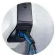
text_image
Technical diagram of a mechanical assembly with numbered components and directional arrows indicating motion or movement.text_image
Technical diagram of a vehicle's internal components with numbered parts and assembly linestext_image
Technical diagram showing labeled components of an electrical or mechanical device with numbered parts and connection detailstext_image
L3 X L2 X L1 X SOR74 1 3 N X X 16 15 18 ①text_image
Charging station interface 192.168.123.123/operator/settings MENNEKES Charging station interface 4.50-5211 State Settings ► Default Operator System Documentation OCFP ChargePointID ChargePointID AMTRON The at that is sent to the backend and used by the backend to verify the charge point - show more. 234 Connection Type GSM The type of data connection to be used to connect to the backend system. If any, Use this option to double backend communication completely Access Point Name (APR) chargecloudide Access Point Name of the mobile network to be used when establishing connections to the backend system on the back-in mode: APR Username Username to be used for authenticating with the Access Point of the mobile network for connecting with the backend systems APR Password Password to be used for authenticating with the Access Point of the mobile network for connecting with the backend systems Save Save & Restart Settings Default & Reset→ "6.6 Apparaat controleren"
De groene led knippert.
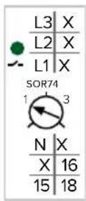
Eén fase:
natural_image
Line drawing of a device with a plug inserted into the socket (no text or symbols)| ... Error activation message | ... | Corrective actions |
| ... ... ... ... | ||
| ... Residual current detected via sensor | ... | The saftey mechanism is reset to its original state every time the plug is removed and automatically after 15 minutes if the plug is not removed. If problem persists check yellow current transformer and its connection. |
| ... ... ... ... ... |

text_image
Technical diagram of a mechanical assembly with labeled parts, showing internal components and a zoomed-in detail view.Afb. 21: Laadstekker noodontgrendelen
Apparaat openen.
→ "5.4 Apparaat openen"
https://www.chargeupyourday.com/

text_image
Diagram of a device with labeled parts including an RFID scanner, memory card, and various electronic components.text_image
Diagram of a device control panel with numbered labels pointing to key componentstext_image
Technical diagram of a remote control device with numbered components for identificationBild 4: Vy bakifrån
text_image
Technical diagram of an electronic device rear panel with numbered components for identificationnatural_image
White medical device with blue cable and a small black component, placed on a plain surface (no visible text or symbols)natural_image
Person interacting with a white device labeled 'MENVERES' and blue cable, pointing at a screen (no visible text or symbols on device body)natural_image
White medical device with blue cable and connector, no visible text or symbols
natural_image
White remote control device with black lid and buttons (no visible text or symbols)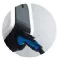
natural_image
White and black electronic device with a small black port, no visible text or symbols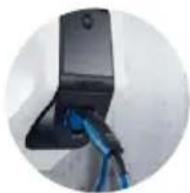
text_image
Technical diagram of a mechanical assembly with numbered components and directional arrows indicating motion or movement.text_image
Technical diagram of a tank with numbered parts and exploded view, showing internal components and assembly lines.text_image
Technical diagram showing labeled components of an electrical or mechanical device with numbered parts and directional arrowstext_image
L3 X L2 X L1 X SOR74 1 3 N X X 16 15 18 1text_image
MENNECKPI ① ② ECUtext_image
Charging station interface 192.168.123.123/operator/settings MENNEKES Charging station interface 4.50-5211 State Settings ► Default Operator System Documentation OCPP ChargePointID ChargePointID APTRON The if that is sent to the backend and used by the backend to identify the charge point - show more... Connection Type GSM Access Point Name (APR) chargecloudide Access Point Name of the mobile network to be used when establishing connectors to the backend system on the back-in modem APR Username Username to be used for authenticating with the Access Point of the mobile network for connecting with the backend system APR Password Password to be used for authenticating with the Access Point of the mobile network for connecting with the backend system Save Save & Restart Settings Default & Resort■ "Operator Current Limit (A)"
Endast varianter Professional+ (E) 7,4 / 22 (PnC):

Endast varianter Professional(+) 7,4 / 22 (PnC):
natural_image
Line drawing of a device with an attached plug and cable, no text or symbols presenttext_image
I >15 mm *klack*| ... Error activation message | ... | Corrective actions |
| ... ... ... ... | ||
| ... Residual current detected via sensor | ... | The saftey mechanism is reset to its original state every time the plug is removed and automatically after 15 minutes if the plug is not removed. If problem persists check yellow current transformer and its connection. |
| ... ... ... ... ... |

text_image
Technical diagram of a mechanical assembly with labeled parts, showing internal components and a zoomed-in detail view.https://www.chargeupyourday.com/

14 Ordlista
5.3.2 Innrette sikring....13
5.4 Åpne apparatet....14
5.5 Montere apparatet på veggen 15
5.6 Elektrisk tilkobling....16
6 Igangsetting....17
8.3 Firmware Update....37
9 Feilretting....37
9.1 Feilmeldinger 37
9.2 Reservedeler 38
9.3 Nødløsne ladepluggen.... 38
text_image
Diagram of a device with labeled parts including an RFID scanner, memory card, and paper sheetsFig. 2: Leveringsomfang (eksempel)
text_image
Technical diagram of a device control panel with numbered components for identificationFig. 3: Sett forfra (eksempel)
- LED-infofelt
- Husets overdel
- Vindu for energimåler
- Frontpanel
- RFID-kortleser
- Ladekontakt type 2 med hengslet lokk ^1)
text_image
Technical diagram of a remote control device with numbered components for identificationFig. 4: Sett bakfra
text_image
Technical diagram of an electronic device casing with numbered components for identificationnatural_image
White medical device with blue cable and a small screen, placed on a plain surface (no visible text or symbols)Fig. 6: Kabeloppheng
3.5 Energimåler
natural_image
Person interacting with a white MENNIXE'S electric shock absorber device (no visible text or symbols on device body)natural_image
White medical device with blue cable, no visible text or symbols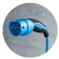
Fast tilkoblet ladekabel med ladekobling type 2
Disse versjonene har fast tilkoblet ladekabel. Med disse kan du lade alle elbiler med plugg av type 2. Du trenger ikke bruke en separat ladekabel.
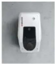
natural_image
White electronic device with a black control panel and indicator lights (no visible text or symbols)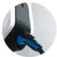
Ladekontakt type 2 med hengslet lokk for bruk av separat ladekabel
natural_image
White and black handheld device with a small screen, against a plain gray background (no visible text or symbols)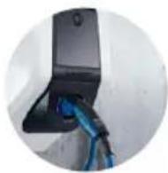
text_image
Technical diagram of a mechanical assembly with numbered components and directional arrows indicating motion or flow.text_image
Technical diagram of a vehicle chassis with numbered components and wiring connectionsFig. 11: Feste på veggen
→ "5.3.2 Innrette sikring"
text_image
Technical diagram showing labeled components of an electrical or mechanical device with numbered parts and connection detailstext_image
L3 X L2 X L1 X SOR74 1 3 N X X 16 15 18 1text_image
Charging station interface 192.168.123.123/operator/settings MENNEKES Charging station interface 4.50-5211 State Settings ► Default Operator System Documentation OCPP ChargePointID ChargePointID APTRON The if that is sent to the backend and used by the backend to identify the charge point - show more... Connection Type GSM Access Point Name (APR) chargecloudide Access Point Name of the mobile network to be used when establishing connectors to the backend system on the back-in modem APR Username Username to be used for authenticating with the Access Point of the mobile network for connecting with the backend system APR Password Password to be used for authenticating with the Access Point of the mobile network for connecting with the backend system Save Save & Restart Settings Default & ResortFig. 15: Oppbygging nettgrensesnitt
text_image
MENNEKES N O A R S U V W ECU 1 ALARM REACYFig. 16: Sette inn SIM-kort
▶ Sett SIM-kortet inn i micro-SIM-sporet (1).
natural_image
Line drawing of a device with a plug inserted into the socket (no text or symbols visible)| ... Error activation message | ... | Corrective actions |
| ... ... ... ... | ||
| ... Residual current detected via sensor | ... | The saftey mechanism is reset to its original state every time the plug is removed and automatically after 15 minutes if the plug is not removed. If problem persists check yellow current transformer and its connection. |
| ... ... ... ... ... |

text_image
Technical diagram of a mechanical assembly with labeled parts, showing internal components and a zoomed-in detail view.Fig. 21: Nødlosne ladepluggen
- Åpne apparatet.
→ "5.4 Åpne apparatet"
▶ Sett den røde spaken (2) inn på firkantaksen på aktuatoren (1). Den røde spaken er festet med en kabelbinder i nærheten av aktuatoren.
Drei den røde spaken på aktuatoren 90° med urviseren.
https://www.chargeupyourday.com/

NO
14 Ordliste
https://www.chargeupyourday.com/faqs/

text_image
Diagram of a device with labeled parts including an RFID scanner, memory card, and various electronic components.text_image
Technical diagram of a device control panel with numbered components for identificationtext_image
Technical diagram of a remote control device with numbered components for identificationtext_image
Technical diagram of an electronic device rear panel with numbered components for identificationnatural_image
White medical device with blue cable and a small black component, placed on a plain surface (no visible text or symbols)- ábra: Kábeltartó
3.5 Fogyasztásmérő
natural_image
Person interacting with a white MINNES device, no visible text or symbols on the device or backgroundnatural_image
White medical device with blue cable and connector, no visible text or symbols
natural_image
White remote control device with a black display and circular ports (no visible text or symbols)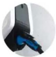
natural_image
White and black handheld device with a small circular button on the side (no visible text or symbols)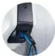
https://www.chargeupyourday.com/

4 Müszaki adatok
text_image
Technical diagram of a mechanical assembly with numbered components and directional arrows indicating motion or movement.text_image
Technical diagram of a mechanical assembly with numbered components and exploded viewtext_image
Technical diagram of an electrical terminal block with labeled components and wiring connectionstext_image
Technical diagram showing labeled components of an electrical or mechanical device with numbered parts and connection detailstext_image
L3 X L2 X L1 X SOR74 1 3 N X X 16 15 18text_image
Charging station interface 192.168.123.123/operator/settings MENNEKES Charging station interface 4.50-5211 State Settings ► Default Operator System Documentation OCPP ChargePointID ChargePointID APTRON The if that is sent to the backend and used by the backend to identify the charge point - show more... Connection Type GSM Access Point Name (APR) chargecloudide Access Point Name of the mobile network to be used when establishing connectors to the backend system on the back-in modem APR Username Username to be used for authenticating with the Access Point of the mobile network for connecting with the backend system APR Password Password to be used for authenticating with the Access Point of the mobile network for connecting with the backend system Save Save & Restart Settings Default & Resortnatural_image
Line drawing of a device with a plug inserted into the socket (no text or symbols)text_image
... Error activation message ... ... ... ... Residual current detected via sensor ... ... ... ... ... Corrective actions The safety mechanism is reset to its original state every time the plug is removed and automatically after 15 minutes if the plug is not removed. If problem persists check yellow current transformer and its connection.
text_image
Technical diagram of a mechanical device with labeled parts, showing internal components and a zoomed-in detail view.https://www.chargeupyourday.com/

HU