
EURO 403/100D - Compressor EINHELL - Free user manual and instructions
Find the device manual for free EURO 403/100D EINHELL in PDF.

| Product type | Air compressor |
| Brand | Einhell |
| Model | EURO 403/100D |
| Supply voltage | 400 V ~ 50 Hz |
| Motor power | 2.2 kW / 3 HP |
| Compressor speed | 1000 min⁻¹ |
| Service pressure | 10 bar |
| Compressed air tank capacity | 90 liters |
| Effective air flow at 6 bar | 240 l/min |
| Theoretical suction power | 400 l/min |
| Sound power level LWA | 97 dB(A) |
| Sound pressure level LPA | 88 dB(A) |
| Dimensions (L x W x H) | 115 x 54 x 87 cm |
| Weight | 63 kg |
| Motor type | Three-phase with circuit breaker protection |
| Recommended oil | SAE 5W/40 or equivalent |
| Oil change interval | First change after 100 h, then every 500 h |
| Suction filter cleaning | Every 300 operating hours |
| Safety valve | Set to maximum permissible pressure (10 bar) |
| Warranty | 2 years |
Frequently Asked Questions - EURO 403/100D EINHELL
User questions about EURO 403/100D EINHELL
0 question about this device. Answer the ones you know or ask your own.
Ask a new question about this device
Download the instructions for your Compressor in PDF format for free! Find your manual EURO 403/100D - EINHELL and take your electronic device back in hand. On this page are published all the documents necessary for the use of your device. EURO 403/100D by EINHELL.
USER MANUAL EURO 403/100D EINHELL
natural_image
Mechanical assembly diagram showing a wheel, pulley, and mounting bracket (no text or labels)Öleinfüllstopfen:
natural_image
Technical illustration of a mechanical assembly with a hand adjusting a component (no text or symbols visible)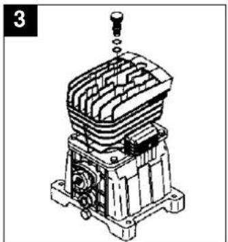
natural_image
Technical line drawing of a mechanical assembly with no visible text or symbols-Ölwechsel:
natural_image
Technical line drawing of a mechanical device with a wrench inserted, no visible text or symbols
natural_image
Technical line drawing of a mechanical assembly with no visible text or symbolsD
natural_image
Technical line drawing of a mechanical component with exploded view (no text or symbols)●Nachspannen des
Keilriemens:
Netzstecker ziehen.
Entfernen Sie den
Keilriemenschutz.
General safety instructions
Important! The following basic safety precautions have to be taken when using this compressor in order to guard against the risk of electric shock, injury and fire. Read and note these instructions before you use the compressor.
-
Keep your work area tidy - There is a higher risk of accident in an untidy work area.
-
Make allowance for environmental conditions
-
Never leave the compressor in the rain. Never use the compressor in damp or wet conditions. Provide good lighting. Never use the compressor near combustible liquids or gases.
-
Protect yourself from electric shocks
- Avoid physical contact with earthed parts, e.g. pipes, radiators, cookers, refrigerators.
- Keep children away!
- Do not allow other persons to touch the compressor or its cable. Keep them out of your work area.
- Keep your compressor in a safe place
- When the compressor is not being used it should be kept in a dry, locked room out of the reach of the children.
- Do not overload your compressor
- It is better and safer to work within the quoted power range.
- Wear suitable work clothes
- Do not wear loose garments or jewellery. There is a risk of them catching on moving parts. Rubber gloves and non-slip shoes are recommended when working outdoors. Put on a hair net if you have long hair.
- Wear goggles
- Wear a breathing mask when working in dusty conditions.
- Never use the cable for any purpose other than that intended
Never tow the compressor by its cable and never pull the power plug out of the socket by the cable. Protect the cable from heat, oil and sharp edges.
- Do not overreach
- Avoid abnormal postures. Stand squarely and keep your balance at all times.
- Look after your compressor
- Keep your compressor clean so that it works well and reliably. Follow the maintenance instructions. Check the power plug and cable regularly and have them replaced by a specialist if you discover any damage. Check any extension cables regularly and replace if damaged.
- Pull out the power plug
- Whenever the compressor is not being used and before carrying out any maintenance work.
- Do not leave any tools on the compressor
- Before you switch on the compressor, make sure that all wrenches and setting tools have been removed.
- Avoid accidental starts
- Make sure that the switch is turned to OFF before you connect the compressor to the power supply.
- Extension cables for outdoor use
- Use extension cables outdoors only if they are approved and marked accordingly.
- Concentrate at all times
- Watch your work. Be sensible. Do not use the compressor if your mind is not on your work.
- Examine your compressor for signs of damage
- Before you use the compressor again, carefully check its safety devices or any slightly damaged parts to make sure that they are
GB
working properly and as intended. Check moving parts to make sure that they are in good working order and are not jammed or damaged. All parts have to be properly fitted in order to be sure of meeting all the machine's requirements.
Damaged safety devices and parts have to be repaired or replaced by a customer service workshop unless otherwise stated in this manual. Damaged switches have to be replaced by a customer service workshop. Do not use any tools with a switch that cannot be turned on and off.
- Important!
- For your own safety, use only such accessories and auxiliary equipment as are listed in this manual or which are recommended and specified by the manufacturer. There is a high risk of suffering a serious accident if you use tools or accessories which are not listed in this manual or in the catalogue of recommended tools and accessories.
- Have an electrician carry out repairs
- Repairs are to be carried out only by a qualified electrician. If not, the user may suffer serious accidents.
- Connect a dust extraction system
- If there are facilities for connecting a dust extraction system, check that the system is indeed connected and being used.
- Noise
- The compressor's noise is measured in accordance with IEC 59 CO 11, IEC 704, DIN 45635 Part 21, and NFS 31-031 (84/537/EEC). The machine noise may exceed 85 dB(A) at the workplace. In this case, noise protection measures need to be introduced for the user.
Keep these safety instructions in a safe place.
GB
Read this manual carefully before putting the compressor into operation!
| Technical data 403/50 D 403/100 D | ||
| Power supply 400 V ~ 50 Hz 400 V ~ 50 Hz | ||
| Motor rating in kW/h.p. 2,2 / 3 2,2 / 3 | ||
| Compressor speed in rpm 1000 1000 | ||
| Operating pressure in bar 10 10 | ||
| Pressure vessel volume in litre 50 90 | ||
| Effective air delivery rate at 6 bar in l/min. 240 240 | ||
| Theoretical intake rate in l/min. 400 400 | ||
| Sound power level LWA in dB(A) 97 97 | ||
| Sound pressure level LPA in dB(A) | 88 88 | |
| Machine dimensions in cm | 115 x 47 x 76 | 115 x 54 x 87 |
| Machine weight in kg | 54,7 | 63,0 |
| Article No. | 40.312.10 | 40.316.10 |
| Identification No. | 01021 01021 |
The machine is radio-suppressed in accordance with EC Guidelines 82/499 EEC. The unit is not intended for outdoor operation as per Article 3 of EC Directive 2000/14/EC.
Points to note when setting up the compressor
●Examine the machine for signs of transit damage. Report any damage immediately to the company which delivered the compressor.
●Before you put the compressor into operation, check the oil level in the compressor pump.
●The compressor should be set up near the working consumer
●Avoid long air lines and long supply lines (extensions).
●Make sure the intake air is dry and dust-free.
●Do not set up the compressor in damp or wet rooms.
●The complete compressor has undergone an official prototype test. The machine can be put into operation without further testing by a technical inspector (e.g. TÜV). It is important to keep the supplied factory certificate and test certificate in a safe place.
●The above mentioned certificates have to be presented on request to representatives of your factory inspectorate. In this connection see also the manufacturer's certificate „Notes for the user“.
Safety instructions for working with compressed air and paint sprayers
Important! Note the pertinent accident prevent regulations in force in your area!
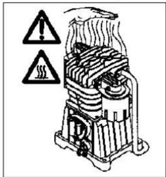
Compressors and lines reach high temperatures during operation. Avoid contact! Risk of burns!
Gases or vapours drawn in by the compressor have to be kept free of constituents that may cause fire or explosions inside the compressor.
When you disconnect the hose coupling, hold the coupling element in your hand to prevent
injury from the whiplashing hose. Wear goggles when working with the blow-out gun. Injuries may easily result from foreign bodies and blasted parts.
Never point the blow-out gun at other persons and never use it to clean clothes that are still being worn.
Note the safety instructions for paint spraying!
Important! Note the pertinent accident prevent regulations in force in your area!
●Never process paints or solvents with a flash point below 21°C.
●Never heat paints or solvents.
●It is imperative to use filtering equipment (face masks) when processing harmful liquids. Note also the information concerning safety precautions published by the manufacturers of these liquids.
GB
●Smoking is prohibited during the spraying operation and in the work room. Paint vapours are highly flammable.
●Make sure there are no open fires or open lights in the work room. Sparking machines are not to be used.
●Do not keep or consume food and drink in the work room. Paint vapours are harmful.
●The work room has to be bigger than 30 m ^3 and have sufficient ventilation for spraying and drying. Never spray into the wind.
It is always imperative to observe the regulations of your local police authorities when spraying combustible or hazardous substances.
●Never process media such as white petroleum spirit, butyl alcohol and methylene chloride with the PVC pressure hose (reduced life span).
Operation of pressure vessels in accordance with the pertinent pressure vessel regulations
(e.g. Section 13 of the German Pressure Vessel Act)
- An operator of a pressure vessel is required to keep the pressure vessel in good working order, to operate it properly, to supervise its use, to carry out essential maintenance and repair work immediately, and to introduce essential safety measures according to requirements.
- The supervisory authorities may order essential safeguards from case to case.
-
A pressure vessel may not be operated if it has any defects which constitute a danger to employees or third parties.
-
If pressure vessels of groups III, IV, VI and VII suffer damage to any pressure-bearing walls, resulting in them being taken out of operation in accordance with Section 13 Paragraph 3 of the German Pressure Vessel Act, the operator has to notify the supervisory authorities and discuss what action is to be taken.
Putting the compressor into operation
Assembling the wheels and the rubber buffers:
Fit the wheels as shown in Figure 1. Make sure that the valve is on the outside!
Fit the supplied rubber buffers to the support foot as shown in Figure 2.
natural_image
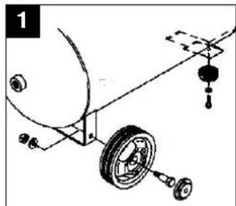
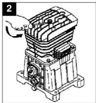
Mechanical assembly diagram showing a wheel, pulley, and hanging component (no text or labels)Oil plug:
Use a screwdriver to remove the oil plug from the cylinder head (fig 2) and press the green oil plug into the hole.
natural_image
Technical illustration of an industrial electrical component with a hand adjusting its internal structure (no text or symbols visible)
natural_image
Technical line drawing of a mechanical assembly with no visible text or symbolsConnecting to the power supply:
The compressor is delivered with a mains cable and a CEE plug.
Important!
Before putting the compressor into operation for the first time, check that the direction of rotation is correct. See the direction arrow on the belt cover or on the fan wheel.
The three-phase motor is protected by an overload circuit-breaker so that its winding will not be damaged by phase failure, overloading or short-circuiting. The overload switch disconnects when the nominal current is exceeded.
After a brief cooling period you can switch on again by turning the ON/OFF switch at the compressor pushbutton.
Long power supply cables, cable extensions, cable reels etc. cause the voltage drop and may prevent the motor from starting up. At low temperatures below 0°C there is a risk of the motor not starting due to stiffness.
GB
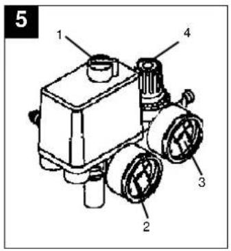
Explanation of the compressed air fittings
1 On/Off switch
2 Pressure gauge (to indicate the vessel pressure)
3 Pressure gauge (to indicate the set pressure)
4 Pressure reducing valve (pressure setting)
Maintenance and cleaning
●Condensation water
Let out the condensation water daily by opening the drain valve (bottom of the pressure vessel).
●Safety valve
The safety valve is set to the maximum pressure of the pressure vessel. It is prohibited to adjust the safety valve or to remove its lead seal.
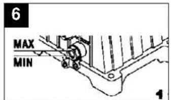
●Regular oil level checks
The level of oil has to be visible in the sight-glass between the red check-point mark and the upper edge of the sight-glass (fig. 6).
Changing the oil: Recommended grade SAE 5W/40 or equivalent.
The first oil change should be carried out after 100 operating hours. Thereafter you should
drain the oil and replace it with new oil at intervals of 500 operating hours.
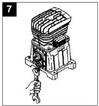
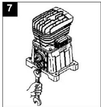
●Changing the oil
Switch off the motor and pull the power plug out of the socket-outlet. After letting off any air pressure you can remove the oil drain plug from the compressor pump by un-screwing. To prevent the oil escaping out of control, hold a small piece of metal guttering underneath the drain plug to direct the oil into a container. If any oil still remains inside, tilt the compressor a little.
Take the old oil to an official old oil disposal station.
When the old oil has run out, screw the oil drain plug/sight-glass back in place.
Pull the green plug out of the cylinder head and fill in new oil until the level in the sight-glass reaches the red dot (fig 6).
Then press the green fplug into the hole.
natural_image
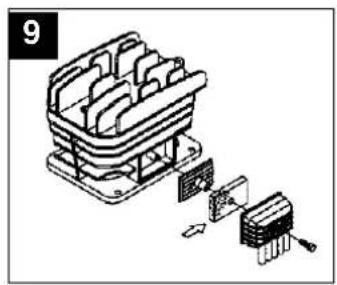
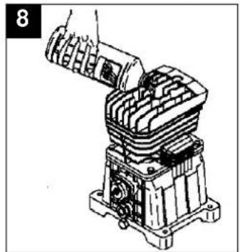
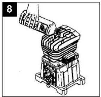
Technical line drawing of a mechanical device with a wrench and handle (no text or symbols)●Cleaning the intake filter

natural_image
Technical line drawing of a mechanical assembly with no visible text or symbolsThe intake filter prevents dust and dirt being drawn into the machine. This filter has to be cleaned at intervals of no longer than 300 operating hours. A clogged intake filter has a considerable negative effect on the compressor's power.
The filter can be removed as shown in Figure 9. Wash out the filter with petroleum ether and reinsert.
Caution! Wait until the compressor has cooled completely!
Risk of burns!
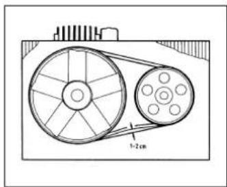
●Tensioning the V-belt
Pull out the power plug. Remove the V-belt guard. Undo the four motor fixing screws and use a wooden wedge between the pump and the motor to lever the motor toward the rear and tension the V-belt. The V-belt is correctly tensioned if you can depress it approx. 1-2 cm with your fingers.
cool off before switching on again. Avoid touching hot components and pipe lines.
Ordering replacement parts
Please quote the following data when ordering replacement parts:
●Type of machine
●Article number of the machine
●Identification number of the machine
●Replacement part number of the part required
Possible causes of machine failure
Overloading of the motor and hence triggering of the overload circuit-breaker may result from:
●An excessively high mains voltage
●Excessively high ambient temperatures and an insufficient air supply
●Defective compressor valves or a leaking non-return valve
●A low level of oil, sluggish connecting rod bearings Leave a.c. motors enough time to

natural_image
Mechanical assembly diagram showing a wheel, pulley, and attached components (no text or labels)d'huile:

natural_image
Technical illustration of an industrial electrical switch assembly (no text or symbols visible)
natural_image
Technical line drawing of a mechanical assembly with no visible text or symbols●Vidange:
natural_image
Technical line drawing of a mechanical device with a wrench inserted, no visible text or symbols
natural_image
Technical line drawing of a mechanical assembly with no visible text or symbolsnatural_image
Mechanical assembly diagram showing a wheel, pulley, and mounting bracket (no text or labels)Olievulstop:
natural_image
Technical line drawing of an electrical component with a hand adjusting its internal structure (no text or symbols visible)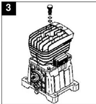
natural_image
Technical line drawing of a mechanical assembly with no visible text or symbolsnatural_image
Technical line drawing of a mechanical device with a wrench inserted, no visible text or symbols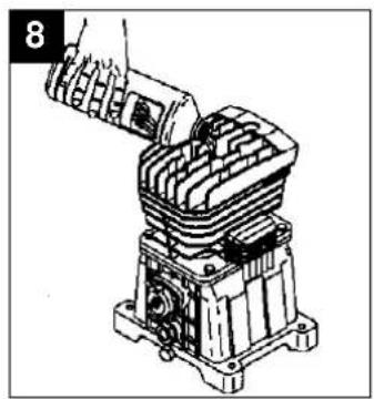
natural_image
Mechanical assembly diagram showing a hand inserting a component into a multi-chambered housing (no text or symbols visible)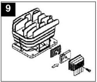
natural_image
Exploded view diagram of a mechanical component with internal structure and mounting base (no text or symbols)natural_image
Mechanical assembly diagram showing a wheel, pulley, and mounting bracket (no text or labels)natural_image
Technical illustration of a mechanical assembly with a hand adjusting a component (no text or symbols visible)
natural_image
Technical line drawing of a mechanical assembly with no visible text or symbolsConexión eléctrica:
natural_image
Technical line drawing of a mechanical device with a wrench and handle (no text or symbols)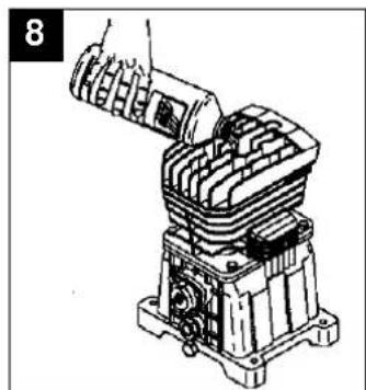
natural_image
Technical line drawing of a mechanical assembly with no visible text or symbolsnatural_image
Isometric line drawing of a mechanical device with internal components and a separate component (no text or symbols)recambio
natural_image
Mechanical assembly diagram showing a wheel, pulley, and mounting bracket (no text or labels)natural_image
Technical illustration of a mechanical assembly with no visible text or symbols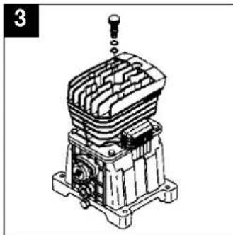
natural_image
Technical line drawing of a mechanical assembly with no visible text or symbolsLigação eléctrica:
●Troca de óleo:
natural_image
Technical line drawing of a mechanical component with a wrench inserted (no text or symbols)natural_image
Mechanical assembly diagram showing a motor or engine component being inserted into a housing (no text or symbols visible)natural_image
Isometric line drawing of a mechanical component with exploded view (no text or symbols)●Reesticar a correia
trapezoidal:
Tire a ficha da tomada.
natural_image
Mechanical assembly diagram showing a wheel, pulley, and attached components (no text or labels)natural_image
Mechanical assembly diagram showing a hand operating a component with no visible text or symbols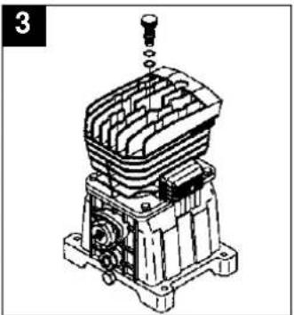
natural_image
Technical line drawing of a mechanical assembly with no visible text or symbolsElanslutning:
●Oljebyte:
natural_image
Technical line drawing of a mechanical device with a hand securing a hook (no text or symbols)S
natural_image
Technical line drawing of a mechanical assembly with no visible text or symbolsnatural_image
Isometric line drawing of a mechanical assembly with internal components and a separate component (no text or symbols)S
natural_image
Mechanical assembly diagram showing a wheel, pulley, and attached components (no text or labels)Öljyntäyttötulppa:
natural_image
Technical illustration of an industrial electrical switch assembly (no text or symbols visible)
natural_image
Technical line drawing of a mechanical assembly with no visible text or symbolsSähköliitäntä:
-Öljynvaihto:
natural_image
Illustration of a mechanical assembly with a hand holding a wrench (no text or symbols)natural_image
Mechanical assembly diagram showing a motor or engine component with no visible text or symbolsN
natural_image
Mechanical assembly diagram showing a wheel, pulley, and attached components (no text or labels)Oljeplugg:
natural_image
Technical illustration of a mechanical assembly with a hand adjusting a component (no text or symbols visible)
natural_image
Technical line drawing of a mechanical assembly with no visible text or symbolsElektrisk tilkobling:
Kompressoren leveres med en nettkabel med CEE-støpsel.
Viktig!
●Oljeskift:
natural_image
Illustration of a hand using a wrench to adjust or install a mechanical component (no text or symbols visible)natural_image
Mechanical assembly diagram showing a robotic arm interacting with a cylindrical component (no text or symbols visible)natural_image
Mechanical assembly diagram showing a wheel, pulley, and hanging weights (no text or labels)natural_image
Technical illustration of a mechanical assembly with a hand adjusting a component (no text or symbols visible)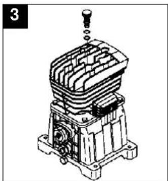
natural_image
Technical line drawing of a mechanical component with no visible text or symbolsΗλεκτρική σύνδεση:
●Αλλαγή λαδιού:
natural_image
Technical line drawing of a mechanical device with a hand holding a hook (no text or symbols)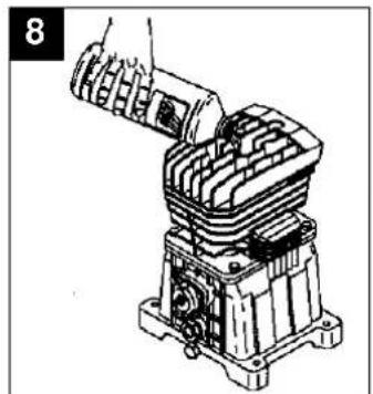
natural_image
Mechanical assembly diagram showing a hand operating a component with no visible text or symbolsλαδιού.
natural_image
Isometric line drawing of a mechanical component with internal parts and a separate assembly detail (no text or symbols)ανταλλακτικών
natural_image
Mechanical assembly diagram showing a wheel, pulley, and mounting bracket (no text or symbols)natural_image
Technical line drawing of a mechanical assembly with no visible text or symbols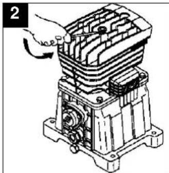
natural_image
Mechanical assembly diagram showing a hand operating a housing component (no text or symbols visible)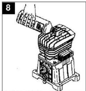
natural_image
Technical line drawing of a mechanical assembly with no visible text or symbolsnatural_image
Technical line drawing of a mechanical device with a hand holding a hook (no text or symbols)aspirazione
natural_image
Isometric line drawing of a mechanical device with internal compartments and exploded view (no text or symbols)natural_image
Mechanical assembly diagram showing a wheel, pulley, and mounting bracket (no text or symbols)natural_image
Technical illustration of an industrial electrical component with a hand adjusting its internal structure (no text or symbols visible)
natural_image
Technical line drawing of a mechanical assembly with no visible text or symbolsEl-tilslutning:
natural_image
Technical line drawing of a mechanical assembly with a hand inserting a component (no text or symbols visible)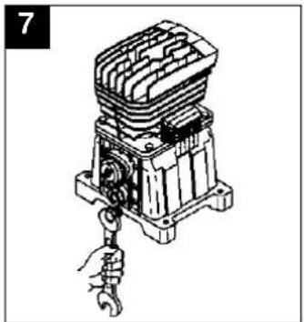
natural_image
Technical line drawing of a mechanical device with a wrench inserted, no visible text or symbolsnatural_image
Exploded view diagram of a mechanical component with internal parts and mounting base (no text or symbols)⑤ EINHELL GARANTIBEVIS
The guarantee period begins on the sales date and is valid for 2 years.
Responsibility is assumed for faulty construction or material or functional defects.
Any necessary replacement parts an necessary repair work are free of charge.
We do not assume responsibility for consequential damage.
Your customer service provider
NL EINHELL-GARANTIE
DK EINHELL GARANTIBEVIS
Eschenstraße 6 · D-94405 Landau/Isar (Germany)
Technical changes subject to change
Brook House, Brookway
North Cheshire Trading Estate
Prenton, Wirral, Cheshire
CH 43 3DS
Tel. 0151 6084802, Fax 0151 6086339
S.C. A Ap. 9 Sector 1
RO 75 121 Bucharest
Tel. 01 4104800, Fax 01 4103568
CZ Poker Plus S.R.O.
Areal Vu Bechovice
Budava 10B
CZ-19011 Praha - Bechovice 911
Tel.+Fax 02579 10204
- Öleinfüllstopfen:
- D
- ●Nachspannen des
- Keilriemens:
- General safety instructions
- GB
- Points to note when setting up the compressor
- Safety instructions for working with compressed air and paint sprayers
- Note the safety instructions for paint spraying!
- Operation of pressure vessels in accordance with the pertinent pressure vessel regulations
- Putting the compressor into operation
- Assembling the wheels and the rubber buffers:
- Oil plug:
- Connecting to the power supply:
- Important!
- Explanation of the compressed air fittings
- Maintenance and cleaning
- ●Condensation water
- ●Safety valve
- ●Regular oil level checks
- ●Changing the oil
- Take the old oil to an official old oil disposal station.
- Caution! Wait until the compressor has cooled completely!
- ●Tensioning the V-belt
- Ordering replacement parts
- Possible causes of machine failure
- ●Vidange:
- Olievulstop:
- recambio
- Ligação eléctrica:
- ●Reesticar a correia
- trapezoidal:
- Elanslutning:
- ●Oljebyte:
- S
- Öljyntäyttötulppa:
- Sähköliitäntä:
- -Öljynvaihto:
- N
- Oljeplugg:
- Elektrisk tilkobling:
- Viktig!
- Ηλεκτρική σύνδεση:
- ●Αλλαγή λαδιού:
- ανταλλακτικών
- aspirazione
- El-tilslutning:
- ⑤ EINHELL GARANTIBEVIS
- NL EINHELL-GARANTIE
- DK EINHELL GARANTIBEVIS
Brand : EINHELL
Model : EURO 403/100D
Category : Compressor