DHKI 752 880 C - Cooker AMICA - Free user manual and instructions
Find the device manual for free DHKI 752 880 C AMICA in PDF.

User questions about DHKI 752 880 C AMICA
0 question about this device. Answer the ones you know or ask your own.
Ask a new question about this device
Download the instructions for your Cooker in PDF format for free! Find your manual DHKI 752 880 C - AMICA and take your electronic device back in hand. On this page are published all the documents necessary for the use of your device. DHKI 752 880 C by AMICA.
USER MANUAL DHKI 752 880 C AMICA
natural_image
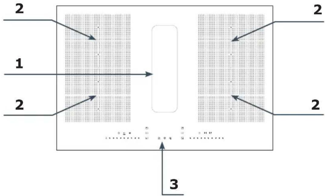
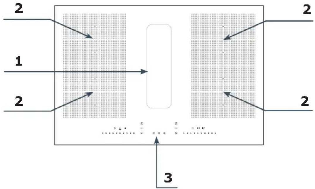
Technical line drawing of a rectangular electronic device with a central display and surrounding components (no text or symbols)Induction hob with extractor / Muldenlüfter / Integrovaná indukční varná deska s digestoří / Integrovaná indukčná varná doska s digestorom / Table de cuisson à induction intégrée avec hotte aspirante / Geïntegreerde inductiekookplaat met afzuigkap / Integrirana indukcijska ploča s napom / Integrirana indukcijska kuhalna plošča z napo
DHKI 752 880 C
EN- Table of contents
SAFETY INSTRUCTIONS FOR USE 11
UNPACKING
16
DISPOSAL OF OLD APPLIANCE 16
TIPS ON SAVING ELECTRICITY 17
BASIC INFORMATION ABOUT YOUR APPLIANCE 18
OPERATE YOUR INDUCTION HOB 18
COOKWARE CHARACTERISTICS 18
RESIDUAL HEAT INDICATOR "H" 21
BEFORE USING THE APPLIANCE FOR THE FIRST TIME 21
EXAMPLES OF POWER SETTINGS 21
AIR EXTRACTION MODE IN WHICH THE AIR IS EXPELLED OUTSIDE THROUGH THE
VENTILATION DUCT. 22
AIR RECIRCULATION MODE WITH ACTIVATED CARBON FILTER 22
BEFORE INSTALLING 23
INSTALL THE APPLIANCE 24
DIMENSIONS OF THE APPLIANCE 24
PACKAGE CONTENTS 25
MAKE THE WORKTOP RECESS 25
INSTALLATION IN AIR RECIRCULATION MODE 27
INSTALLATION IN AIR EXTRACTION MODE IN WHICH THE AIR IS EXPELLED OUTSIDE
THROUGH THE VENTILATION DUCT. 31
ELECTRICAL DIAGRAM 35
PIPE SET FOR INDUCTION HOB WITH EXTRACTOR 36
OPERATION 38
CLEANING AND CARE 44
TROUBLESHOOTING 45
TECHNICAL SPECIFICATION 46
WARRANTY AND AFTER SALES SERVICE 47
WARRANTY 47
GARANTIE, NACHVERKAUF-SERVICE 87
GARANTIE 87
CS- Obsah
POKYNY K BEZPEČNÉMU POUŽÍVÁNÍ 89
ROZBALENI 94
LIKVIDACE POUŽITÝCH ZAŘÍZENÍ 94
JAK SETRIT ENERGII 95
ZÁKLADNÍ INFORMACE O ZAŘÍZENÍ 96
ZÁSADA FUNGOVÁNÍ INDUKČNÍ DESKY 96
CHARAKTERISTIKA NÁDOBÍ 96
UKAZATEL ZBYTKOVÉHO TEPLA „H“ 99
PŘED PRVNÍM ZAPNUTÍM VARNÉ DESKY 99
PŘÍKLAD NASTAVENÍ VÝKONU QHŘÍVÁNÍ 99
PROVOZNÍ REŽIM DIGESTOŘE 100
REŽIM ODTAHU (ODVÁDĚNÍ VZDUCHU DO VENTILAČNÍHO KANÁLU) 100
REŽIM POHLCQVAČE (RECIRKULACE VZDUCHU) 100
INFORMACE PRED INŞTALACI 101
INSTALACE A MONTÁŽ 102
ROZMĚRY ZAŘÍZENÍ 102
OBSAH BALENÍ 103
PŘÍPRAVA DESKY NÁBYTKU DO VESTAVĚNÍ VARNÉ DESKY 103
INSTALACE V REŽIMU POHLCOVAČE (RECIRKULACE VZDUCHU) 105
INSTALACE V REŽIMU ODSÁVÁNÍ (ODSÁVÁNÍ VZDUCHU DO VENTILAČNÍHO POTRUBÍ)
109
RIESENIE PROBLEMOV 161
SPECIFIKACIA 162
ZÁRUKA, POPREDAJNÝ SERVIS 163
ZÁRUKA 163
RESTWARMTE-INDICATOR "H" 216
VOOR HET EERSTE GEBRUIK VAN DE KOOKPLAAT 216
VOORBEELDEN VAN DE INSTELLINGEN VOOR DE WARMTEAFGIFTE 216
WERKMODUS VAN DE AFZUIGKAP 217
AFZUIGMODUS (LUCHTAFVOER NAAR VENTILATIEKANAAL) 217
ABSORBERSTAND (LUCHTRECIRCULATIE) 217
INFORMATIE VOORAFGAAND AAN DE INSTALLATIE 218
INSTALLATIE EN MONTAGE 219
AFMETINGEN VAN HET APPARAAT 219
INHOUD VAN DE VERPAKKING 220
VOORBEREIDING VAN HET WERKBLAD VOOR INBOUW VAN DE KOOKPLAAT 220
INSTALLATIE IN ABSORBERSTAND (LUCHTRECIRCULATIE) 222
INSTALLATIE IN DE AFZUIGSTAND (LUCHTAFVOER IN HET VENTILATIEKANAAL) 226
From now on, your daily housework will be easier than ever before. Your appliance Air*optionally easy to use and extremely efficient. After reading these Operating Instructions, operating the appliance will be easy.
Before being packaged and leaving the manufacturer, the appliance was thoroughly checked with regard to safety and functionality.
Before using the appliance, please carefully read these Operating Instructions. By following these instructions carefully you will be able to avoid any problems in using the appliance. It is important to keep these Operating Instructions and store them in a safe place so that they can be consulted at any time.
Follow these instructions carefully in order to avoid possible accidents.
Sincerely,
Amica
SAFETY INSTRUCTIONS FOR USE
- Before using the appliance for the first time, carefully read its Operating Instructions. This will ensure user safety and prevent damage to the appliance.
- NOTE: Never leave cooking unattended.
- This appliance is designed for household use only.
- When operating the induction hob in close proximity to a radio, television, or other radio-frequency emitting device, verify the proper operation of the hob's touch sensor controls.
- The hob must be installed by a qualified professional.
- Do not install the appliance near a refrigerator.
- During use, the appliance and its heating elements may become hot. Exercise caution to avoid accidental contact with hot surfaces. Children less than 8 years of age shall be kept away from the appliance unless continuously supervised.
- This appliance is intended for use by persons aged 8 years and over, as well as those with reduced physical, sensory, or mental capabilities or a lack of experience and knowledge, provided they are supervised or have received instruction regarding safe operation. Supervision by a responsible person is required during the use of this appliance. Ensure that children do not play with the appliance. Children must not clean or maintain the appliance without supervision.
- Never leave cooking fats or oils unattended as they can easily catch fire. If grease catches fire, DO NOT use water - immediately turn off the appliance and cover the flames with a lid or fire blanket.
- Note! Keep the heating surface clear and do not allow objects to accumulate on the heating surface, as this could cause a fire.
- If the hob surface cracks, immediately disconnect the appliance from the power supply to prevent electric shock.
- Placing metal objects such as knives, forks, spoons, lids, and aluminium foil on the hob surface can cause them to become extremely hot and cause severe burns when touched.
• After cooking, turn off the hob using its controls. - Do not operate the appliance using external timers or stand-alone remote control systems.
- Do not use steam-generating appliances to clean the hob.
- The furniture in which the hob is installed must be resistant to temperatures up to 100°C. This temperature resistance requirement applies to all furniture components in the vicinity of the hob, including veneers, edges, plastic surfaces, adhesives, and paints.
- The appliance may only be used once fitted in kitchen furniture.
- Repairs to electrical appliances may only be conducted by specialists. Improper repairs can be dangerous to the user.
- The appliance is only disconnected from the mains by switching off the safety circuit breaker.
• Children shall not play with the appliance. - People with implanted medical devices (such as pacemakers, insulin pumps, or hearing aids) should take precautions to ensure their devices are not affected by the electromagnetic field generated by this induction hob (20-50 kHz) - consult your physician if you have any concerns.
-
Disconnecting the power resets all appliance settings and indicators. Caution should be exercised when electric power to the appliance is restored.
-
Built-in residual heat indicator can be used to determine if the appliance is on and if it is still hot.
- Do not use plastic containers and aluminium foil. They melt at high temperature and may damage the cooking surface.
- Only use cookware designed for induction hobs.
- Do not allow sugar (solid or liquid), citric acid, salt, or plastic to spill onto the hot cooking surface.
- If sugar or plastic accidentally fall on the hot cooking zone, turn off the hob and wearing oven mitts or heat-resistant gloves, use a scraper designed for ceramic or glass surfaces to immediately and carefully remove the spill from the surface. Protect your hands from burns and injuries.
- When cooking on induction hob only use pots and pans with a flat base having no sharp edges or burrs as these can permanently scratch the cooking surface.
- The induction hob's cooking surface is durable and resistant to thermal shock. It can withstand cold or hot temperature.
- Avoid dropping objects on the cooking surface. Impact from pointed objects, such as spice bottles, may result in cracking or chipping of the cooking surface.
- In the event of a cracked hob surface, immediately disconnect the appliance from the power supply to avoid the risk of electric shock. Spilled liquids may penetrate the damaged areas and come into contact with live electrical components.
- Do not use the cooking surface as a cutting board or work table.
- When the hob is installed in the worktop, metal objects in a cabinet or drawer below can become heated by the airflow from the hob's cooling fan.
- It is important to follow the care and cleaning instructions for the ceramic surface. The warranty
may be voided in the event of misuse or mishandling of the ceramic surface.
- If the power cord is damaged it must be replaced by a specialised service centre.
- Do not use this appliance outdoors or in damp/wet conditions.
- The manufacturer reserves the right to make design and specification changes that do not materially affect the appliance's functionality.
- A hob-integrated downdraft extractor is designed to remove cooking odours. Do not use the appliance for other purposes.
- Connect the downdraft extractor operating in extraction mode to a suitable ventilation duct - do NOT connect the appliance to smoke or flue gas ducts, which are in use.
- Downdraft extractor operating in air recirculation mode requires the installation of an activated charcoal filter.
- Always unplug the appliance before cleaning, replacing the filter, or performing any maintenance.
- Clean the downdraft extractor grease filter at least monthly because grease buildup is flammable and poses a fire hazard.
- Ensure adequate ventilation (fresh air intake) if other equipment, such as liquid fuel stoves or heaters, is operated in the room along with the downdraft extractor to prevent a buildup of combustion byproducts. When the downdraft extractor is operated concurrently with fossil fuel burning appliances that require room air for proper combustion, their safe operation is contingent upon maintaining a maximum underpressure of 0.004 mbar in the vicinity of these appliances - this condition does not apply when the downdraft extractor operates in air recirculation mode.
- Clean the downdraft extractor inside and out at least monthly, following the maintenance in-
structions in this manual. Neglecting to clean the downdraft extractor and replace filters regularly increases the risk of fire.
- When installing a downdraft extractor with external venting, we recommend a backdraft damper at the external outlet. You can purchase a back-draft damper from installer stores.
- The appliance must be easily disconnected from the power supply by switching off a circuit breaker.
- Make sure voltage indicated on the nameplate corresponds to the local mains supply voltage.
- Before use, extend and straighten the power cord.
- For your safety, ensure the power cord is properly installed before connecting the appliance to the mains. Do not connect the appliance to the mains until installation is complete.
- Do NOT operate the downdraft extractor without the grease filter installed.
- Always strictly adhere to regulations issued by the competent local authorities regarding the technical and safety requirements for fume extraction.
- Failing to tighten bolts and fasteners in accordance with these instructions may endanger life and health.
- NOTE! Failure to install bolts and fasteners in accordance with the instructions may result in electrical hazards.
- The manufacturer shall not be liable for any damage or fire caused by the appliance resulting from failure to follow instructions in this manual.
UNPACKING

natural_image
Recycling symbol composed of three chasing arrows forming a triangle (no text or labels)During transportation, protective packaging was used to protect the appliance against any damage. After unpacking, dispose of all packaging materials responsibly to minimise environmental impact. All materials used for packaging the appliance are 100% recyclable and are marked with the appropriate symbol. Note! Packaging materials, including bags, polyethylene, and polystyrene, present a choking hazard
and should be kept away from children at all times during and following unpacking.
DISPOSAL OF OLD APPLIANCE
natural_image
Symbol of a trash bin crossed with a diagonal line, no text or numbers presentIn accordance with European Directive 2012/19/EU and Polish law on waste electrical and electronic equipment, this appliance is marked with the crossed-out waste bin symbol. This symbol indicates that the appliance must not be disposed of with household waste after use. The user is obligated to dispose of this appliance at an authorised collection point for waste electrical and electronic equipment. Local collection points, shops, and local authority departments together provide a recycling scheme.
Properly disposing of old electrical and electronic equipment prevents environmental and health risks caused by hazardous components and improper handling.
TIPS ON SAVING ELECTRICITY

natural_image
Simple black-and-white line drawing of a tree with cloud-like canopy and two wavy lines below (no text or symbols)- Using energy in a responsible way not only saves money but also helps the environment. So let's save energy! And this is how you can do it:
- Use the correct cookware.
- Pans with thick, flat bases can save up to 1/3 on electric energy. Remember to cover pans if possible otherwise you will use a lot more energy!
- Always keep the cooking zones and cookware bases clean.
- Soiled surface can prevent heat transfer – and
repeatedly burnt-on spillages can often only be removed by products which cause damage to the environment.
- When cooking on induction hob only use pots and pans with a flat base having no sharp edges or burrs as these can permanently scratch the cooking surface.
- Do not install the hob in the immediate vicinity of refrigerator / freezer. Heat radiating from cooking can increase the energy consumption of these appliances.
BASIC INFORMATION ABOUT YOUR APPLIANCE
Operate your induction hob
Under the surface glass, there are induction coils that produce pulsing magnetic field. This electromagnetic field penetrates cookware placed on the hob surface causing the cookware to heat up. It is important to use cookware with a suitable base.

Depending on the cookware used and heat setting during cooking, the appliance produces a distinctive whiz. This is normal and does not constitute grounds for a complaint.
Cookware characteristics
- To check that the cookware is suitable for your induction hob, make sure that a magnet strongly attracts its base. The greater the attraction force, the better the cookware.
- Always use high-quality cookware with a perfectly flat base. The use of this kind of cookware prevents hot spots that may result in food sticking to the pot. Pots and pans with thick steel walls provide superior heat distribution. The concave base or deep embossed logo of the manufacturer interfere with the temperature induction control module and can cause overheating of the pot or pan.
- Do not use damaged cookware such as cookware with deformed base due to excessive heat.
natural_image
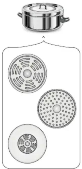
Illustration of a cooking pot with three circular kitchen utensils, no text or symbols present- When you use large ferromagnetic base cookware, whose diameter is less than the total diameter of the cookware, only the ferromagnetic base heats up. This results in a situation where it is not possible to uniformly distribute the heat in the cookware. If the ferromagnetic area is reduced due to inclusion of aluminium parts then the effective heated area can be reduced. Problems with the detection of the cookware could arise or cookware may not be detected at all. To achieve optimum cooking results, the diameter of the ferromagnetic base should match that of the cooking zone. If cookware is not detected in a given cooking zone, it is advisable to try it in a smaller cooking zone.

The high-quality cookware is essential for efficient induction cooking.

It is not recommended to use external induction adapters.
- For induction cooking use only ferromagnetic base materials such as:
- enamelled steel
- cast iron
- special stainless steel cookware designed for induction cooking.
| Kitchen cookware marking |  | Check for marking indicating that the cookware is suitable for induction cooking. |
Stainless Steel
Cookware is not detected
With the exception of the ferromagnetic steel cookware
Aluminium Cookware is not detected
Cast iron
High efficiency
Note: cookware can scratch the hob surface
Enamelled steel
High efficiency
Cookware with a flat, thick and smooth base is recommended
Glass Cookware is not detected
Porcelain Cookware is not detected
Cookware with copper base
Cookware is not detected
- Lid prevents heat from escaping and thus reduces heating time and lowers energy consumption.
- Make sure that cookware base is dry. When filling cookware or when using cookware taken out of the refrigerator make sure its base is completely dry before placing it on the cooking zone. This is to avoid soiling the surface of the hob.
- Ensure the cookware base is smooth, flat against the glass, and the same size as the cooking zone. Select cookware with a diameter corresponding to the graphic outline on the chosen cooking zone. Using cookware that fully covers the cooking zone graphic outline ensures maximum energy transfer and heating efficiency. If you use a smaller cookware, the performance may be lower than expected. A cookware
with a diameter smaller than 140 mm may not be detected by the hob. Always place the cookware in the centre of the cooking zone.
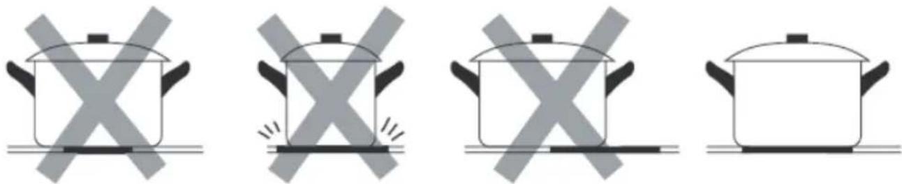
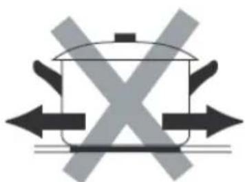
- To prevent scratches, always lift cookware when removing it from the induction hob, never slide it.
natural_image
Diagram of a cooking pot with crossed arrows indicating pressure or movement (no text or symbols)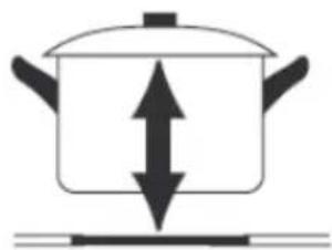
natural_image
Simple line drawing of a cooking pot with upward and downward arrows indicating direction (no text or symbols)- When using the appliance, please refer to the illustration below to properly place the cookware. The cookware should be placed at the location printed on the glass.
text_image
Simple diagram with checkmark and cross symbols on a grid backgroundResidual heat indicator "H"
When you have finished cooking, the induction hob glass within the cooking zone is still hot, this is called residual heat.
If the glass surface is hot, the "H" is shown on the cooking zone display.


When residual heat indicator is on, do not touch the cooking zone as there is a risk of burns and do not place on it any items sensitive to heat!

The "H" residual heat indicator is not displayed during a power outage. However, cooking zones may still be hot!
Before using the appliance for the first time
- Thoroughly clean the induction hob. The hob has a glass surface, therefore handle it with care.
- Odours may be released when you first start your appliance. If this happens, turn on exhaust hood or open the window in the room. Emission of odour is temporary.
Examples of power settings
The following settings are guidelines only. You will need to adjust the setting based on the cookware you are using and the amount of food you are cooking. Experiment with your induction hob to find the settings that best suit your needs.
| Setting Use | |
| 1-2 | Gently heat small amounts of foodMelt chocolate, butter and other products that burn easilyGentle cookingSlow heating |
| 3-4 | ReheatingSimmeringCook rice |
| 5-6 • Fry | pancakes |
| 7-8 | FryingCook pasta |
| P | Boil waterBring soup to a boilDeep Frying |
HOOD OPERATING MODE
This appliance can operate in either air recirculation mode with activated carbon filter or air extraction mode, where the air is expelled through a ventilation duct.
Air extraction mode in which the air is expelled outside through the ventilation duct.
Operation in air extraction mode: When your appliance operates in air extraction mode, the air is expelled outside through the ventilation duct. In order to operate the appliance in air extraction mode you need to remove the activated carbon filter. In this operation mode your appliance is connected via ductwork to the main ventilation duct in the chimney. The appliance should be installed by a qualified installer.
Air recirculation mode with activated carbon filter
In air recirculation mode, the air is drawn from the room into the appliance, filtered, and then returned back into the room through the air outlets. To ensure the effective operation of the appliance in air recirculation mode, you need to install the activated carbon filter, which neutralises odours. For optimal efficiency, the installation of pipe set for an induction hob with extractor is also recommended to enhance air circulation and the distribution of purified air within the room.
Note!
- The optional pipe set for an induction hob with extractor is not included with the appliance and must be purchased separately (PSD 100 DOWNAIR SET). See the "Pipe set for induction hob with extractor" section for illustrations of the kit components and the connection diagram.
- For detailed instructions on replacing the activated carbon filter, please refer to the "Cleaning and care" section.
BEFORE INSTALLING
Before installing the hob, make sure that:
- The work surface must be level and free from any obstructions that could interfere with appliance placement.
- The working surface is made of insulated and heat-resistant material.
- A disconnect switch must be installed in the domestic electrical panel, in accordance with local electrical regulations, to provide complete disconnection from the mains supply.
- To ensure safe disconnection, the disconnect switch must be with a minimum 3 mm isolation break in all poles (or active conductors, where local regulations allow).
- For safety, the disconnect switch must remain easily accessible after the hob is installed to allow for immediate power shutoff.
- If you have any questions about installation procedures or local building codes, contact your local building authorities
- The walls around the hob should be made of heat-resistant materials and easily to clean (e.g. ceramic tiles).
After installing the hob, make sure that:
- Check that the power cord does not interfere with the opening or closing of cabinet doors and drawers.
- Ensure adequate airflow for proper ventilation and cooling to prevent overheating.
Warning
- This hob must be installed by a qualified specialist to ensure safe and correct installation. Do not attempt to install this appliance yourself - professional installation is required.
- To prevent damage to the hob's electronics do not install the hob directly above appliances that generate moisture, such as dishwashers, refrigerators, freezers, washing machines or dryers.
- The hob must be installed to allow efficient heat dissipation, which prevents overheating and prolongs the appliance lifespan.
INSTALL THE APPLIANCE
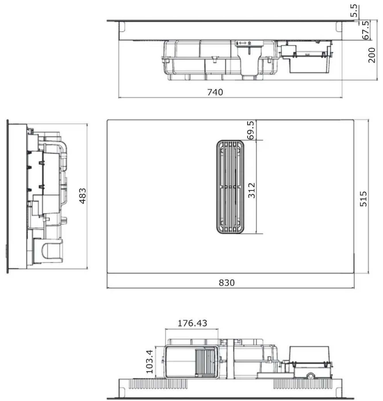
Dimensions of the appliance
Package contents
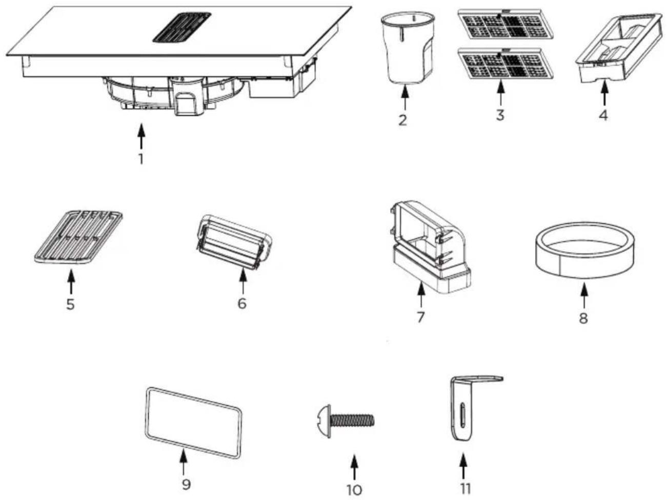
- Induction hob with extractor
- Water container
- Activated charcoal filter
- Grease filter
-
Grille
-
Adapter
- 90° adapter
- Sealing tape
- Seal
- M4*10 screw (x4)
- Mounting bracket (x4)
Note!
The optional pipe set for induction hob with extractor is not included with the appliance and must be purchased separately (PSD 100 DOWNAIR SET). See the "Pipe set for induction hob with extractor" section for illustrations of the kit components and the connection diagram.
Make the worktop recess
- The worktop must be flat and level. Edge of the worktop near the wall must be sealed to prevent ingress of water or other liquids.
- Worktop must be made of materials, including veneer and adhesives, resistant to a temperature of 100°C. Otherwise, veneer could come off or surface of the worktop become deformed.
- Edge of the opening should be sealed with suitable materials to prevent ingress of water.
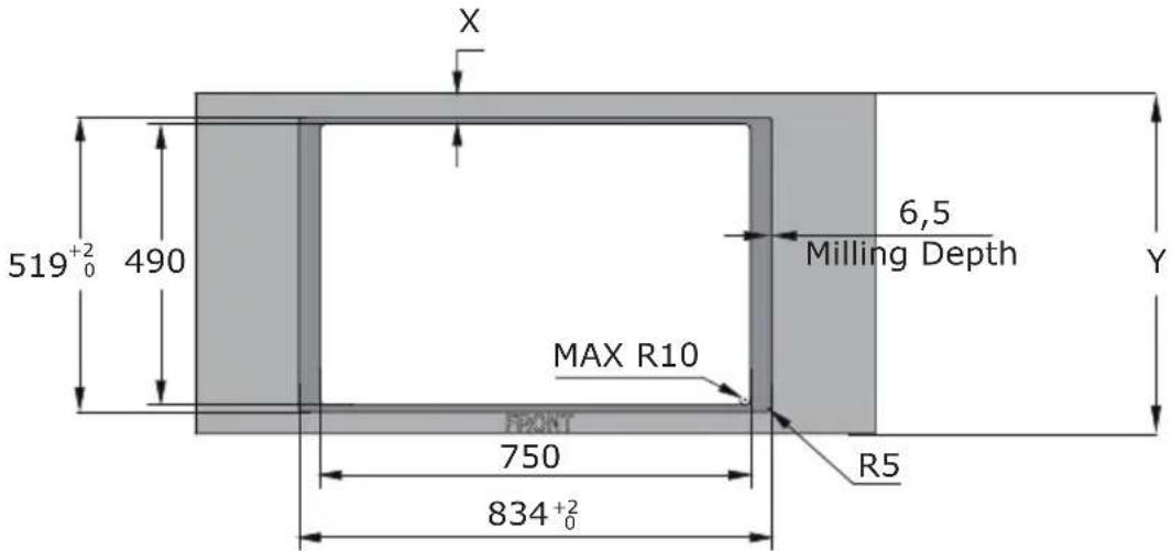
- Worktop opening must be cut to dimensions as shown on figure below (measurement unit [mm]):
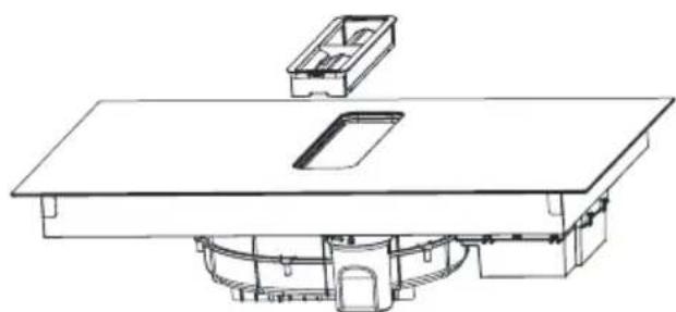
Install your downdraft extractor flush with the worktop
In this solution, the induction hob integrated with an extractor is recessed into the kitchen countertop so that its surface is flush with the countertop.
text_image
X 519⁺²₀ 490 6,5 Milling Depth Y MAX R10 FRONT 750 R5 834⁺²₀Standard installation
In standard installation, the induction hob with an integrated extractor is mounted on the countertop, with its edges protruding above the surface of the countertop.
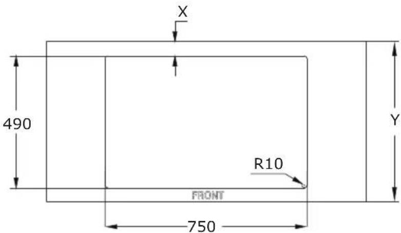
text_image
X 490 R10 FRONT 750 Y| Worktop depth (Y) X | |
| 600-650 mm 54 mm | |
| ≥650 mm 65 mm | |
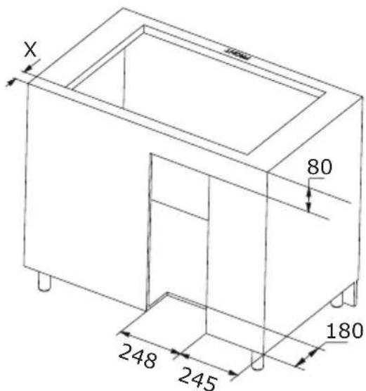
text_image
X 80 180 248 245Installation in air recirculation mode
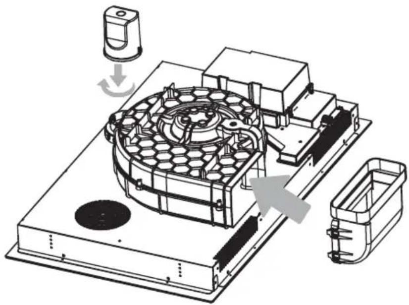
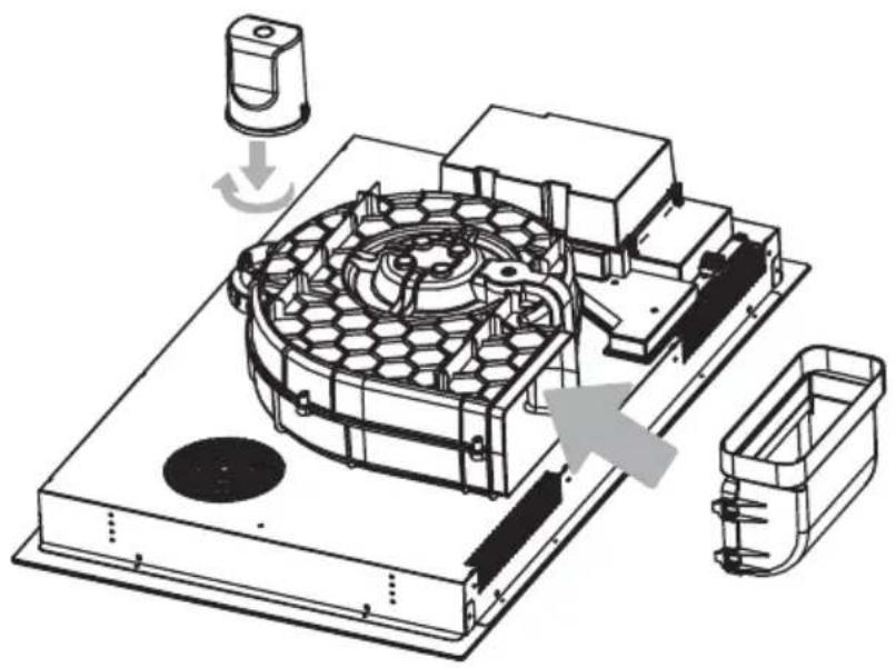
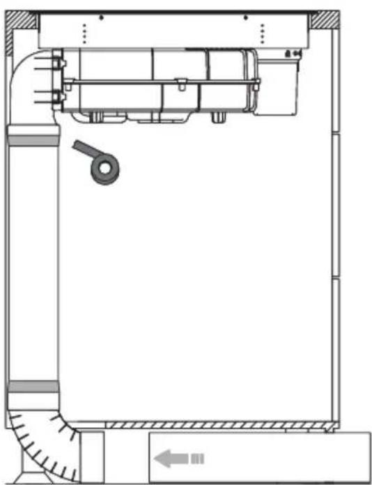
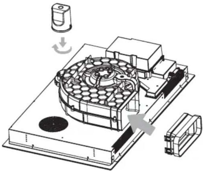
Install the water container by turning it in the direction of the arrow. Then, place the included rubber seal as shown by the arrow in the diagram below. Finally, install the 90° adapter into the designated aperture as illustrated, making sure it fits correctly.
natural_image
Technical line drawing of a mechanical assembly with no visible text or symbolsPlace the downdraft extractor on the worktop and align it properly.

text_image
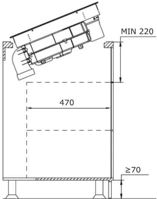
MIN 220 470 ≥70
text_image
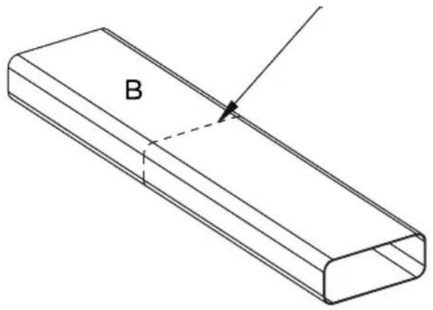
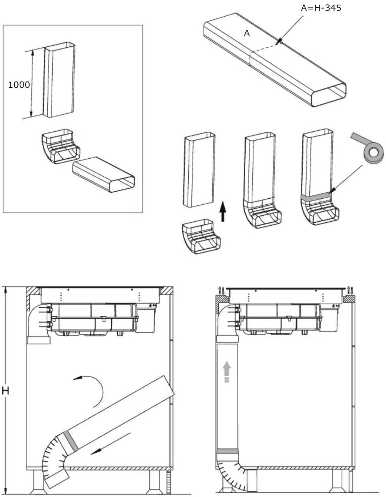
H 130For efficient recirculation, we recommend installing a pipe set for an induction hob with an extractor. This can be purchased separately under the name PSD 100 DOWNAIR SET. Below is an overview of the individual components included. The corresponding dimensions can be found in the "Pipe set for induction hob with extractor" chapter.
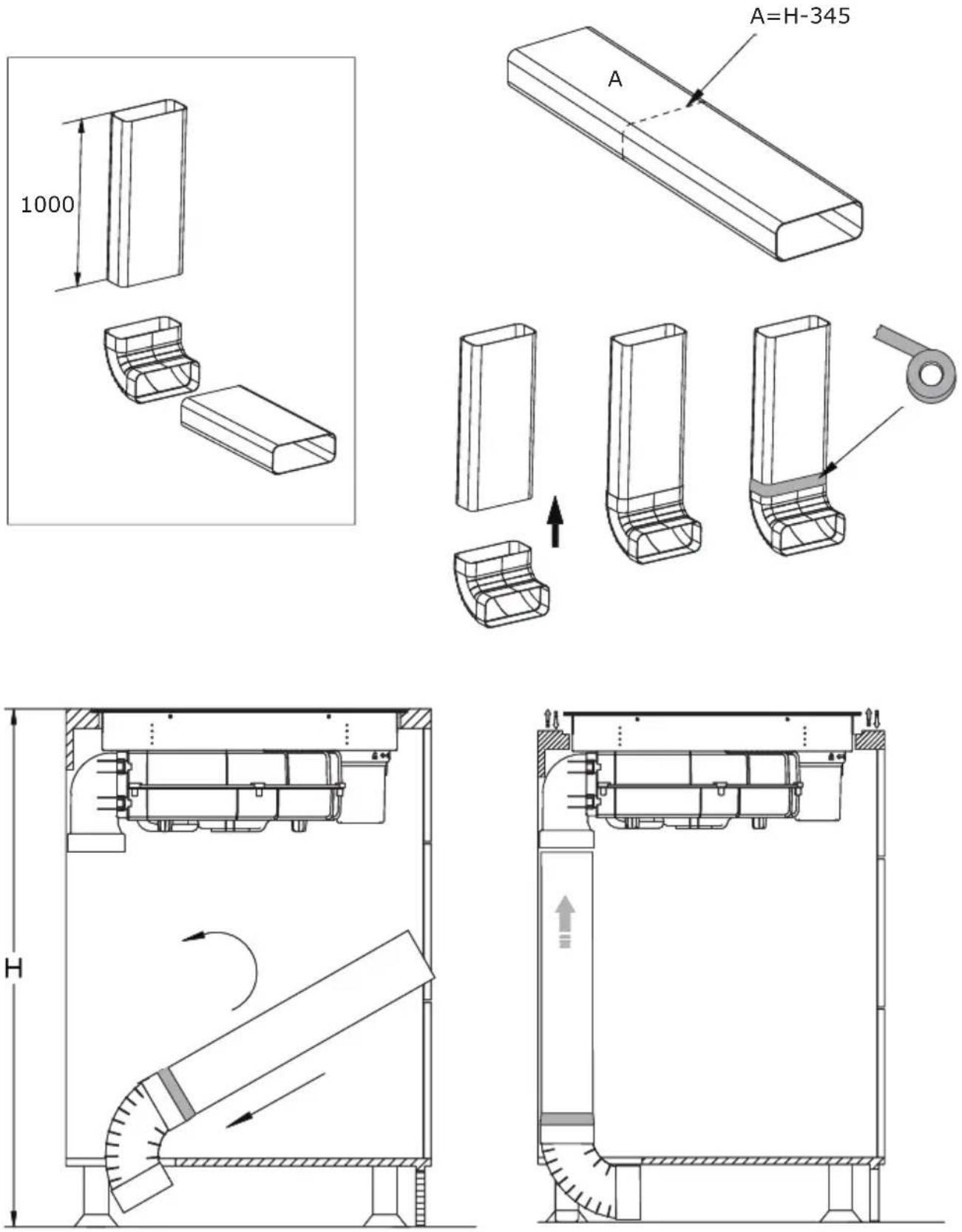
Installation of a pipe set for induction hob with extractor
natural_image
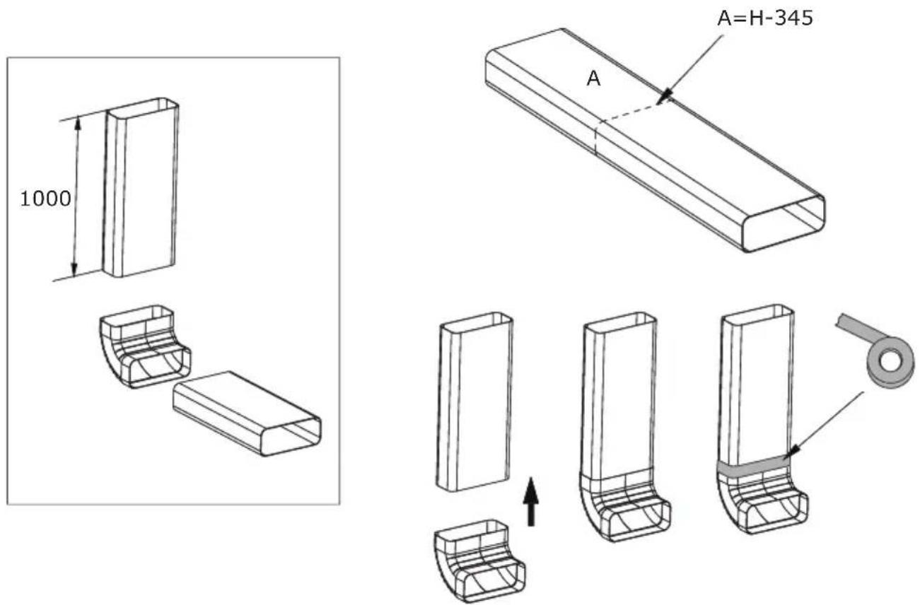
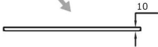
Technical line drawing of a mechanical assembly with dimension label B (no text or symbols beyond basic geometry)Using a saw, cut the duct to the required length.
text_image
BApply the supplied sealing tape to all joints as shown in the illustrations.
natural_image
Technical line drawing of a mechanical assembly with no visible text or symbols
natural_image
Technical line drawing of a mechanical assembly with no visible text or symbols
text_image
Y X MIN 220 ≥70
text_image
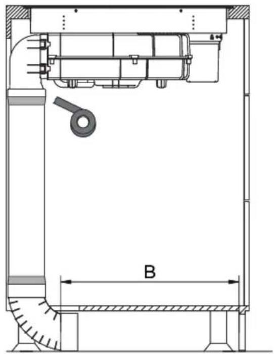
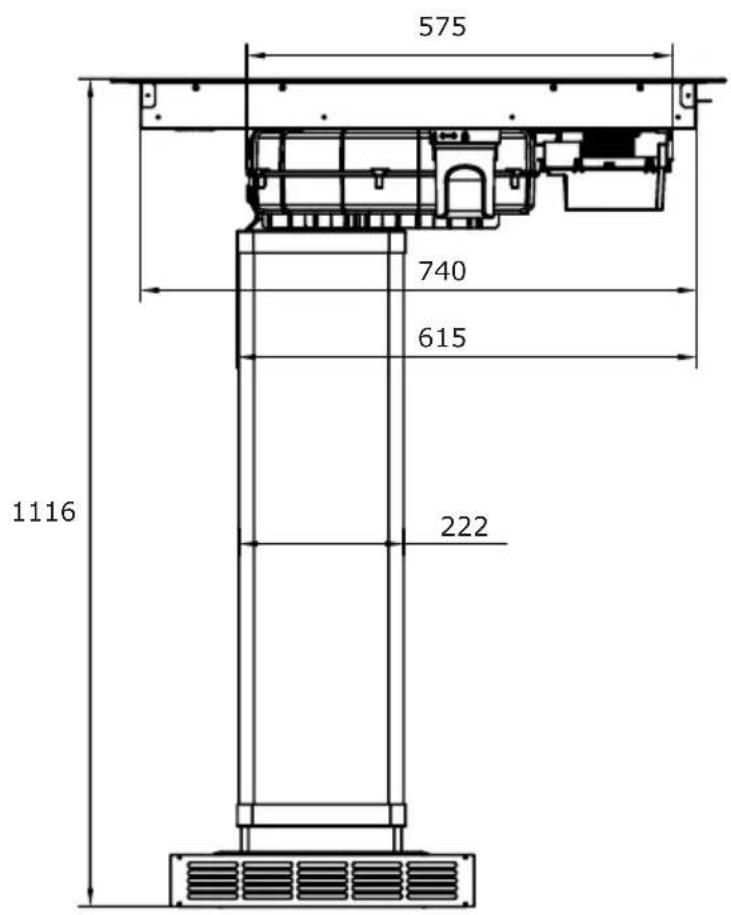
834 750 130,5 125 240 110Finally, attach the connector and the ventilation grille. The exact dimensions of the ventilation grille and the other components of the set can be found in the "Pipe set for induction hob with extractor" section.
text_image
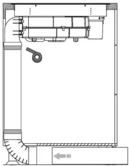
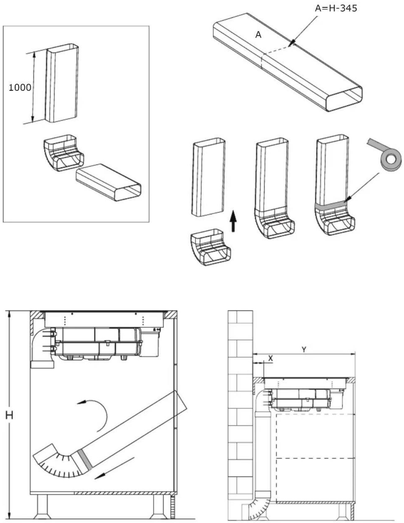
575 740 615 222 1116Installation in air extraction mode in which the air is expelled outside through the ventilation duct.
Method 1
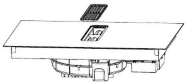
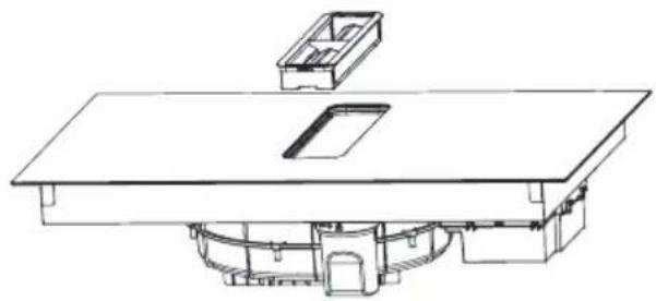
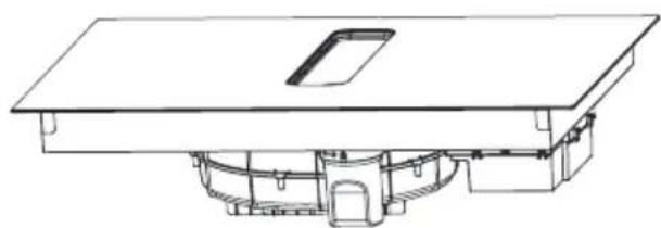
Install the water container by turning it in the direction of the arrow. Then, place the included rubber seal as shown by the arrow in the diagram below. Finally, install the 90° adapter into the designated aperture as illustrated, making sure it fits correctly.
natural_image
Technical line drawing of a mechanical assembly with no visible text or symbolsPlace the downdraft extractor on the worktop and align it properly.

text_image
MIN 220 470 ≥70
text_image
H 130To do this, use the components from the PSD 100 DOWNAIR SET pipe set for an induction hob with an extractor, which must be purchased separately.
natural_image
Technical schematic of a mechanical device with internal components and airflow direction indicators (no text or labels)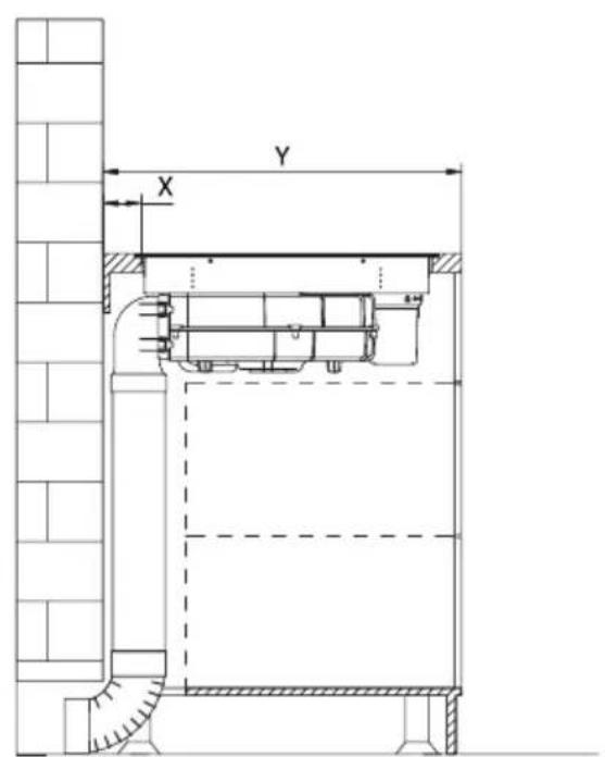
text_image
Y XMethod 2
Install the water container by turning it in the direction of the arrow. Then, place the included rubber seal as shown by the arrow in the diagram below. Finally, install the adapter into the designated aperture as illustrated.

natural_image
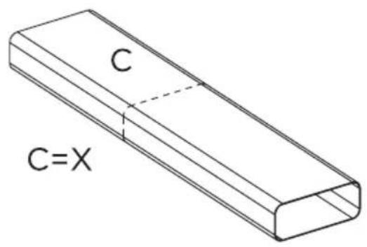
Technical illustration of a mechanical assembly with a hexagonal component and directional arrows indicating motion (no text or symbols)Cut the duct to the correct length with a saw, then attach it to the connector and seal it with tape as shown.
text_image
C C=X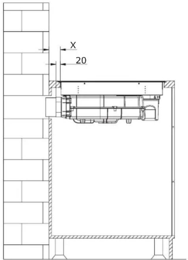
text_image
X 20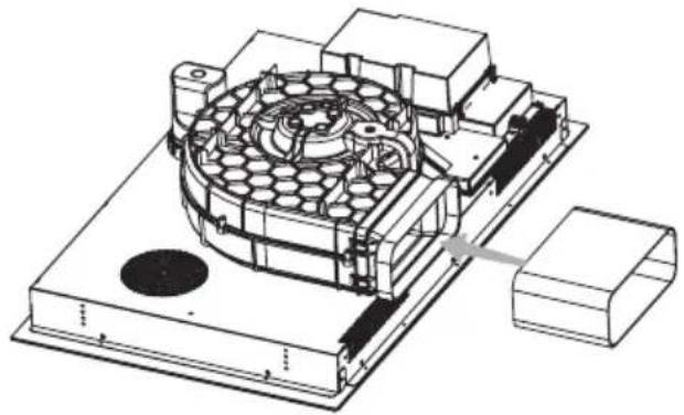
natural_image
Technical line drawing of a mechanical assembly with internal components and mounting base (no text or symbols)
natural_image
Technical illustration of a mechanical device with internal components and a handle (no text or symbols)
natural_image
Architectural line drawing of a building facade with structural elements and a diagonal roof (no text or symbols)
natural_image
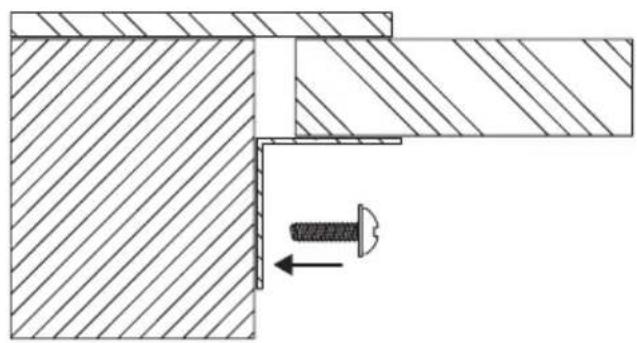
Architectural cross-section diagram of a building facade with structural elements and doorways (no text or labels)Note!
After installing the downdraft extractor, install the four brackets on both sides of it to ensure stability.
natural_image
Technical drawing of a mechanical assembly with hatched areas and a bolt, showing no text or symbolsELECTRICAL DIAGRAM
Supply voltage
AC220-240V 50/60 Hz
AC380-415V
3N\~
50/60Hz
Total power:
7.58kW
Electrical diagram:
| Voltage: Electrical connection | Connection diagram | Power cord | |
| 220-240V~ | 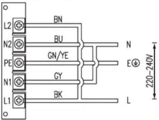 | 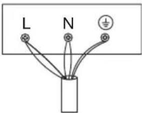 | 5G 2.5mm2H07RN-FL1:BKL2:BNN1:GY N2:BUPE:GN/YE |
| 380-415V~ | 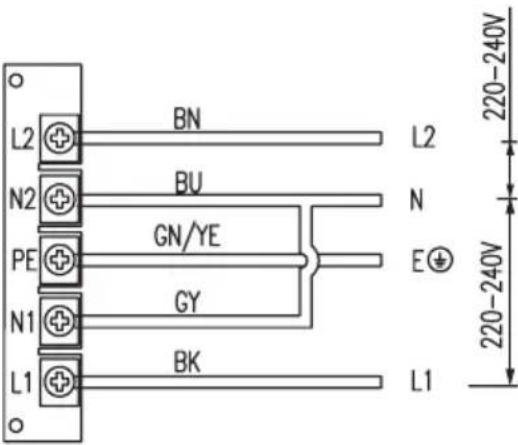 |  | 5G2.5mm2H07RN-FL1:BKL2:BNN1:GY N2:BUPE:GN/YE |
| L1, L2 = PhaseN1, N2 = NeutralPE = Protective Earth | |||
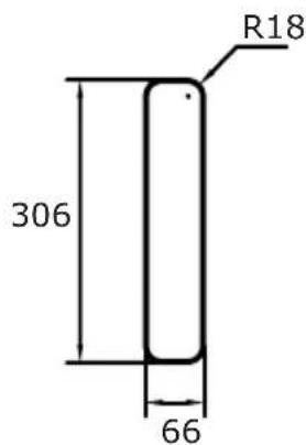
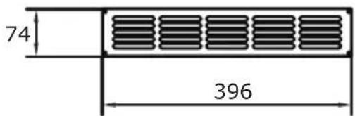
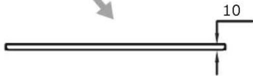
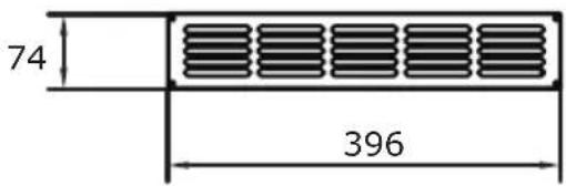
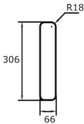
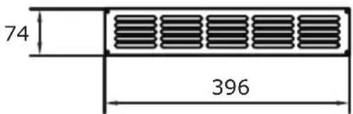
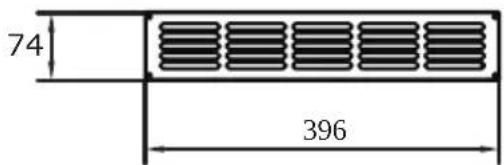
PIPE SET FOR INDUCTION HOB WITH EXTRACTOR
The optional pipe set for an induction hob with extractor (PSD 100 DOWNAIR SET), which is available for separate purchase, includes the mounting elements illustrated in the accompanying drawings.
- 90° connector
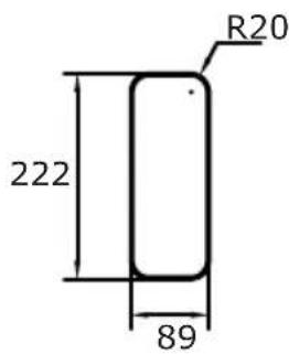
- Straight duct (222*89)
-
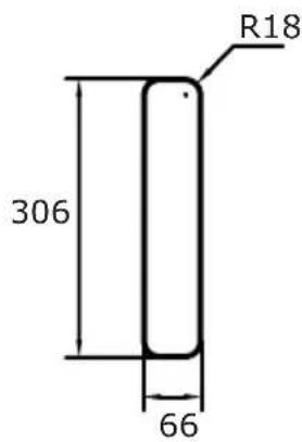
Straight duct (306*66)
-
Connector
- Ventilation grille
- Sealing tape (x2)

text_image
575 740 615 1116 222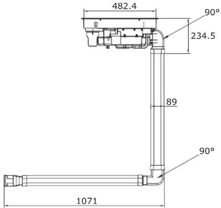
text_image
482.4 90° 234.5 89 90° 1071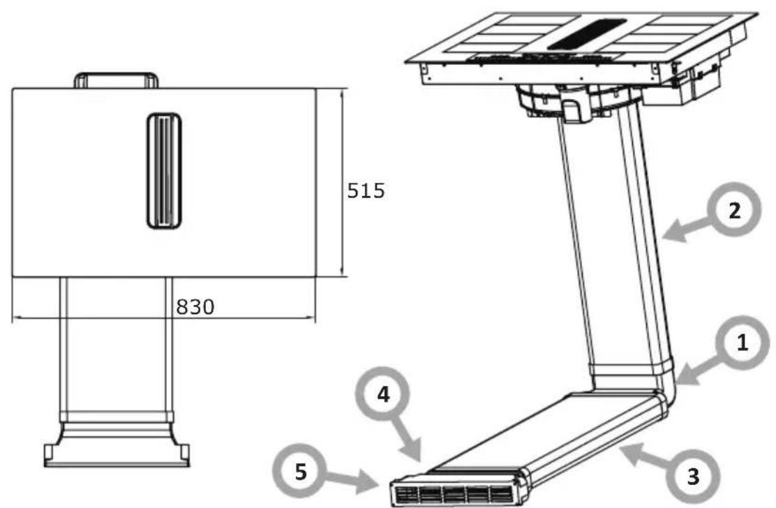
text_image
515 830 2 1 4 3 5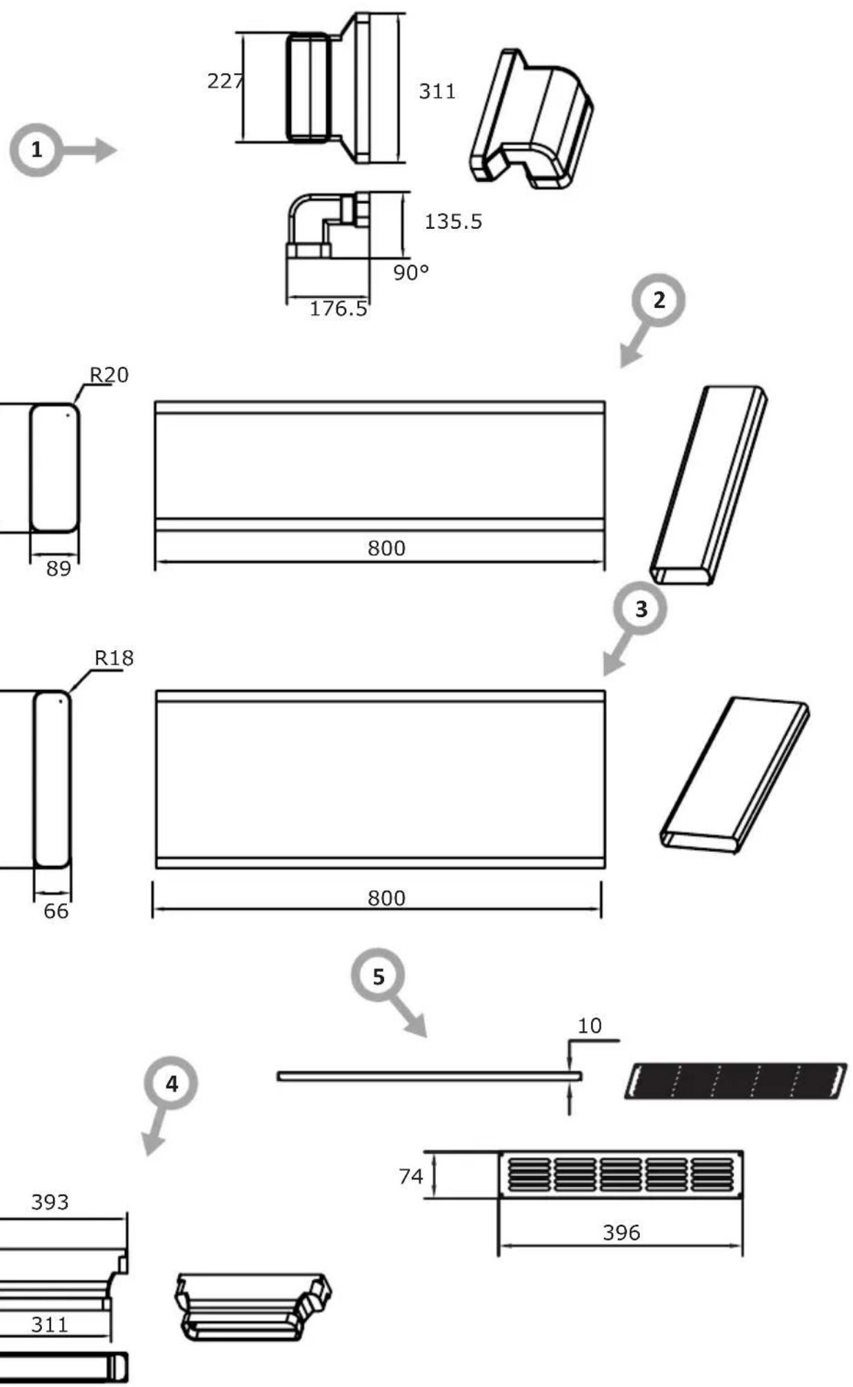

text_image
R20 222 89
text_image
R18 306 66
text_image
393 150 311 70OPERATION
Your appliance

flowchart
graph TD
    A["Section 1"] --> B["Process Block"]
    C["Section 2"] --> B
    D["Section 3"] --> B
    B --> E["Output"]
    style A fill:#f9f,stroke:#333
    style C fill:#f9f,stroke:#333
    style D fill:#f9f,stroke:#333
- Cooker hood ventilation inlet
- Induction cooking zone with booster function
- Touch control panel
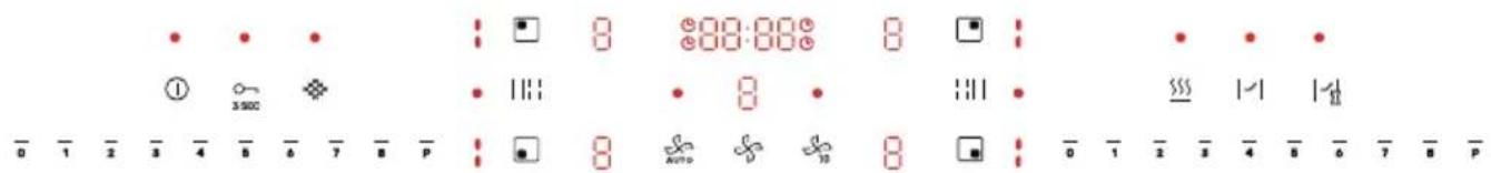
Control panel

text_image
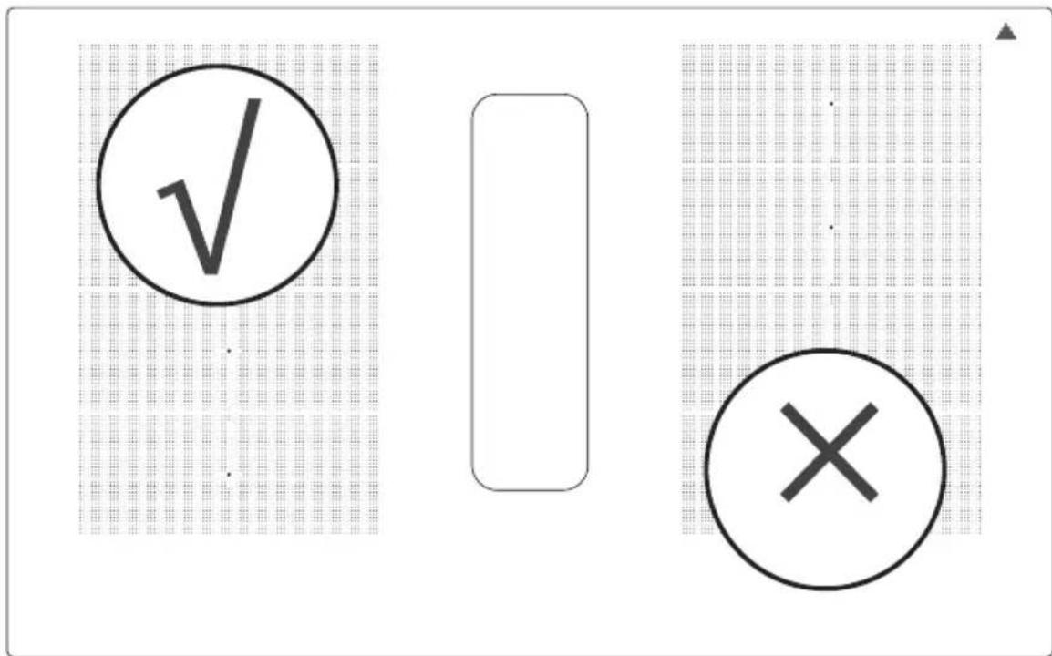
Cropped image showing a sequence of symbols and numbers, possibly representing data or logic instructions.Your appliance features a touch screen control panel:
- Ensure the controls remain clean, dry, and that no objects (e.g. dishes or cloths) obstruct them. Even a thin layer of water can make it difficult to operate the controls.
- The controls on your appliance respond to touch, so there is no need to apply pressure.
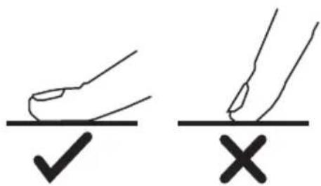
• Each time a touch is detected, you will hear a beep. - Use your finger pad, not the tip of your finger.

text_image
Diagram showing two hand-drawn checkmark and cross symbols on a line, likely indicating correct and incorrect conditions.| Sensor Function Description | ||
 | Sensor ON/OFF | Press and hold down the sensor to switch on the appliance. When the appliance is switched on and the cooker hood is operating (not in delayed switch-off mode): press and hold down the sensor to switch off all cooking zones - the cooker hood will enter delayed shut-off mode. Press and hold down the sensor down again to switch the appliance off completely. When the appliance is on and the cooker hood is off, press and hold down the sensor to switch off the entire device. |
 | ChildLock | Thanks to the ChildLock function, you can lock the control panel, preventing unintended operation - a perfect solution for child safety or while cleaning. To activate the control panel lock, press and hold down the ChildLock sensor. The constantly illuminated light indicates that the lock is active. To deactivate the lock, press and hold the sensor again; the light will turn off, and the control panel will be reactivated. |
| [X7wc] | Bridge function | When the Bridge function is activated, two (vertically aligned) induction zones operate together. It means that these zones will have the same temperature and power settings, which can be adjusted by sliding your finger along the power control sensor. To activate the Bridge mode, briefly touch the Bridge function sensor on the left side. The indicator light will illuminate, and the left induction zones will begin to operate together. To deactivate the Bridge mode, press the Bridge function sensor again. The Bridge function on the right side operates identically to the left-side zones. To activate it, use the dedicated Bridge function sensor located on the right side of the control panel. |
 | Keep Warm function | The Keep Warm function maintains a constant, low temperature on the cooking zone, thanks to which prepared dishes are kept at the right temperature until serving. Touch the keep warm sensor to activate the mode - the LED indicator will illuminate, when the function is active. Touch the sensor again to deactivate the Keep Warm function for the active cooking zone. Hold down the keep warm function sensor to activate or deactivate the Keep Warm mode for all active cooking zones. The function operates only when the power of the cooking zone is greater than 0. |
 - -     [YKD6] [YKD6] | Cooking zone sensorCooker hood fan sensor | Select the sensor of the appropriate cooking zone to access power or operating time settings. After you touch the selected area, the digital display will flash, signalling activation and readiness for configuration. Smoothly slide your finger along the power control sensor to adjust the heating power. If you wish to set the operating time (after previously setting the power), touch the dedicated timer sensor, then use the power control sensor again to select the desired time.Use the cooker hood fan sensor when the hood is off or operating to enter the settings mode - the display will start flashing for 5 seconds. During this time, you can set the hood speed using the power control sensor within the range from 1 to 8 or P, with the maximum level being the 'P' speed or 'power booster'. After setting the fan speed, press the cooker hood fan sensor again to turn it off. You can turn off the appliance also by briefly pressing the cooker hood fan sensor when the hood is on. During the cooker hood operation, the display shows the current operating speed. In lock mode, the display shows the letter 'L'. |
[A0556] | Cooker hood fan automatic mode sensor | This feature enables the cooker hood fan to automatically adjust its speed, operating at an optimal level that corresponds to the operation intensity of the cooking zones. To activate or deactivate the automatic fan function, briefly press the designated sensor. Upon activation, a beep will sound, and the function indicator light will illuminate. When the hob is switched on, the cooker hood will automatically activate. Once all cooking zones are turned off, the hood will enter a delayed shut-off mode after 6 seconds. The cooker hood will switch off after 1 minute. |
  | Delayed cooker hood shut-off sensor | This function delays the shut-off of the cooker hood motor, allowing it to continue operating after cooking to effectively clear residual fumes from the room.Briefly press to activate or deactivate the function - a beep will sound, and the function indicator light will illuminate.When the function is activated, the hood enters a delayed shut-off mode. The appliance will continue to operate for an additional 10 minutes before automatically turning off. |
  | Filter change reminder | After 300 hours of operation, the cooker hood will automatically signal the need to replace the carbon filter by activating an indicator on the control panel. Press and hold down the sensor to switch it off.Briefly press the sensor to display the remaining operating time. |
   | Timer | Briefly press the timer sensor to activate the count-down function - the timer indicator illuminates and the display shows the set time. The maximum allowable time is '99:59' (99 minutes 59 seconds);While the appliance is operating, briefly press the timer sensor to reset the countdown timer and initiate a new countdown cycle.Press and hold down the timer sensor to deactivate the timer function during its operation. |
| Slider-type power control sensor | Slide your finger left or right along the control sensor to adjust the power level of the cooking zone, fan speed, and timer settings. | |
| ●00:00●|—| | Zone timer | The zone timer function allows you to precisely set the operating time for a selected cooking zone, ranging from 00:00 to 3:00 hours. To assign a time to a specific cooking zone, touch the timer sensor when the cooking zone is active. The display will show '00:00', the timer icon will flash for 3 seconds and the timer indicator will illuminate. During this time, you can set the timer using the zone's power control sensor. If no action is taken within 3 seconds, the system will automatically exit the setting mode. To adjust the settings, begin by choosing the desired hour, followed by the number of minutes. Each digit will flash for 3 seconds during adjustment. After this time, the system will automatically move on to the next item. Briefly press the timer sensor to manually advance to the next setting. Once all digits are set, the timer enters operation mode and the timer icon for that cooking zone illuminates continuously.If multiple cooking zones are active but their timers are not operating, the display shows the last approved time for each zone. When a timer is operating, the remaining countdown time is displayed by default. If confirmation of a setting for one of the cooking zones is in progress, the display shows the timer time for that particular zone.When the timer for the particular zone reaches less than 1 minute, the display starts to show the remaining time in seconds. |
| 8 | Display | When a cooking zone is active, its power level is displayed as a number from 1 to 8 or P.If no suitable cookware is placed on the cooking zone, the display shows the letter 'u'.In Keep Warm mode, the display shows '三 |
| ! | Cookware presence indicator light | The indicator light is split into two cooking zones.If any of the zones detects or loses contact with cookware, it will enter the update state: when cookware is detected, the indicator light flashes for 5 seconds and then illuminates continuously. If the cookware is not detected, the indicator light turns off immediately.When the appliance is switched off, all indicator lights remain off.The function applies to all four cooking zones. |
| Error signalling | If the cooker hood encounters a fault, the display shows the letter 'E'; if the fault is related to the induction hob, the specific cooking zone corresponding to the fault shows the letter 'E'.If a fault occurs when the timer function of the heating zone is active, the fault code will be displayed for 10 seconds. Then, the indicator will start flashing, showing the remaining cooking time (which will no longer count down). The countdown will continue once the issue has been fixed. | |
Other information
• Power coordination
When adjusting the operation of an induction hob, the combined maximum power of two cooking zones on the same side should not exceed 3700 W. If, during adjustment, the calculated total output exceeds 3700 W, the output of the unused burner on the same side must be reduced to ensure that the current output corresponds to the user's desired output and that the total output does not exceed 3700 W.
- Set the power limit
To set the power limit, touch and hold down the Child Lock 3s and the lower left cooking zone sensor □You can now set the power limit: Touch the left Cooking Zone Bridge sensor to reduce the power limit. Touch the right Cooking Zone Bridge sensor to increase the power limit. There are 5 power limits available: 2800 W, 3600 W, 4600 W, 5800 W, 7400 W. Touch ON/OFF to confirm the selected power limit or simply wait 30 seconds.
- Energy-saving function of the cooking zone
When all cooking zones are switched off for 5 minutes, the power supply to the zones will be automatically disconnected. During this time, the functions related to the cooking zones will not be active; the cookware indicator and the power level display will be switched off. Briefly press the cooking zone sensor or the ON/OFF sensor to restart the cooking zones.
- Calibration of cookware detection
In standby mode within 1 minute of power-up, press and hold down the ChildLock sensor and timer sensor simultaneously to enter the calibration mode. The digital timer display will show 'CALI'. Then, touch the Bridge function sensor to start the cookware detection calibration. Cookware must not be placed on the hob during calibration. The digital timer display will show a countdown of 5 seconds. Upon successful calibration, the cooking zone's digital display will show the letter 'P' after the countdown. If the calibration is not successful show the letter 'F' will appear. Upon all successful calibrations, the cooking zone digital display will show the letter 'P'. Otherwise show the letter 'F' will appear.
Power levels of the cooking zones:
| Speed 0 1 2 3 4 5 6 7 8 P | |||||||||||
| Power (W) | 0 50 | 180 | 280 | 380 | 600 | 900 | 1200 | 1850 | 3500 | ||
Power levels of the cooking zones when the Bridge function is activated:
| Speed 0 1 | 2 3 | 4 5 | 6 7 | 8 P | |||||||
| Power (W) | 0 1 | 00 | 180 | 280 380 | 760 120 | 0 1800 | 2400 37 | 00 |
Proper routine maintenance and cleaning of the appliance can significantly extend its trouble-free operation. Clean the induction hob with extractor after each use.
Clean the glass surface
Clean the induction hob's glass surface regularly with a soft, damp cloth. Avoid using abrasive cleaning agents or sponges with rough surfaces that may scratch the glass surface. During cleaning and care prevent water from entering the kitchen hood ventilation opening.
natural_image
Technical line drawing of a mechanical assembly with no visible text or symbolsClean the grille
Remove the grille and clean it using a cloth and mild liquid detergent. Avoid using products containing abrasives.
natural_image
Technical line drawing of a mechanical assembly with no visible text or symbolsCleaning the Grease Filter
Carefully withdraw the filter holder, maintaining a horizontal orientation. Empty the collected grease and wash the grease filter by hand or in a dishwasher.

natural_image
Technical line drawing of a solar panel installation with two panels mounted on a table (no text or symbols)Replace the activated carbon filter
To replace the filter, remove the existing filter from the holder and install a new filter. The filter should be replaced after 300 hours of operation.
natural_image
Technical line drawing of a mechanical assembly with no visible text or symbolsClean the water container
Rotate the water container as indicated by the arrow to release and remove it. Then empty the collected water and clean the container. Re-install the water container by turning it in the opposite direction. It is recommended to empty the water container daily or less frequently, depending on usage.
TROUBLESHOOTING
| Problem Possible reason Solution | ||
| The appliance won't turn on | No power Verify that the induction | tion hob is properly connected to the power supply and activated. Check if other lights or appliances in your home are working - if not, check with your neighbours to see if there is a power outage in the neighbourhood. If the problem continues, professional assistance from a qualified technician is required. |
| Touch controls do not respond | Child Lock function is activated. | Deactivate the Child Lock function See the "Operation" section in the manual for details. |
| Touch sensors respond erratically of are difficult to use | The touch sensors may not function correctly if there is moisture present on their surface or if they are touched with only a fingertip. | For reliable sensor operation, ensure the control panel is dry and touch the sensors with the flat of your finger. |
| The glass surface is scratched | You used cookware with rough base surface. | Use cookware with a flat, smooth bottom. See the section "Basic information about your appliance." |
| The induction hob or cooking zone has turned off, an error code is displayed. | Technical fault Make a note of the error code, unplug the induction hob and contact a qualified technician. | |
| The cookware does not heat up | The hob may not detect the cookware if it is not centred on the cooking zone, is too small, or is not designed for induction cooking. | Use cookware suitable for induction cooking. See the section "Basic information about your appliance." Centre the cookware and make sure its bottom matches the size of the cooking zone. |
| Fan noise emitted by induction hob | The induction hob's cooling fan operates automatically to prevent overheating of the electronics. The cooling fan may continue to operate for a short period after the induction hob is deactivated. | This is normal and there is no cause for concern. Do not disconnect the hob from the power supply until the cooling fan has stopped running. |
| Some cookware makes crackling or clicking sounds during cooking | The crackling or clicking sounds can occur because cookware with multiple metal layers expands at different rates when heated. | This is a normal characteristic of cookware and does not warrant concern. |
TECHNICAL SPECIFICATION
| TECHNICAL SPECIFICATION | |
| Model DHKI 752 880 C | |
| Supply voltage 220-240 V~ / 380-415 V 3N~ | |
| Frequency 50/60 Hz | |
| Power 7580 W | |
| Total power of the hob 7400 W | |
| Total power of the hood 180 W | |
| Dimensions (WxDxH) 830x515x200 mm | |
| Package dimensions 965x650x325 mm | |
| Installation dimensions 750x490 mm | |
| Appliance weight 24 kg | |
| Surface material Ceramic glass | |
| Power Levels 1-8, P | |
| Power levels in recirculation mode 1-8, P | |
| Power of cooking zones | |
| Rear cooking zone maximum power 1850 W | |
| Rear cooking zone power boost | 3500 W |
| Front cooking zone maximum power | 1850 W |
| Front cooking zone power boost | 3500 W |
Detailed technical specifications can be found in the device's product card.
The product meets the requirements of European standards EN 60335-1; EN 60335-2-6; EN 60335-2-31.
WARRANTY AND AFTER SALES SERVICE
Warranty
The manufacturer shall not be held liable for any damage caused by improper use of the product.
Service
- The manufacturer recommends that all repairs and adjustments be carried out by the Factory Service Technician or the Manufacturer's Authorized Service Point. For safety reasons, repairs should be referred to professionals.
- Repairs carried out by unqualified persons may seriously endanger the appliance user.
- The minimum warranty period for the appliance offered by the manufacturer, importer or authorized representative is given in the warranty card.
- The warranty shall be void if you make any independent adaptations or alterations, tamper with seals or other appliance safety devices or its parts or interfere with the appliance contrary to operating instructions.
In the event of appliance malfunction, request assistance or repair.
If your appliance needs repair, please contact the service centre. Please see website for address and contact details of our service centre. Before contacting us, please have ready the appliance serial number, which can be found on the identification sticker: For your convenience, please write it down below:
Certifi cate of compliance CE and UKCA
The Manufacturer hereby declares that this product complies with the general requirements pursuant to the following European Directives and analogous UK requirements:
- The Low Voltage Directive 2014/35/EC / Electrical Equipment (Safety) Regulations 2016.
• Electromagnetic Compatibility Directive 2014/30/EC / Electromagnetic Compatibility Regulations 2016. - ErP Directive 2009/125/EC / The Ecodesign for Energy-related Products Regulations 2010 (as amended) for the applicable implementing measures which apply in Great Britain and Northern Ireland, respectively.
and therefore the product has been marked with C€ and UK symbols and the Declaration of Conformity, the Manufacturer has drawn up the declaration and is available to the competent authorities regulating the market.
natural_image
Recycling symbol composed of three chasing arrows forming a triangle (no text or labels)natural_image
Symbol of a trash bin crossed with a diagonal line and a horizontal bar below (no text or labels)natural_image
Simple black-and-white line drawing of a tree with cloud-like canopy and two wavy lines below (no text or symbols)natural_image
Illustration of a cooking pot with three circular kitchen utensils, no text or symbols presenttext_image
Two circled icons: a checkmark inside a circle and a cross inside a circle, placed on a grid background.natural_image
Technical line drawing of a mechanical assembly with no visible text or symbolsnatural_image
Technical line drawing of a mechanical assembly with no visible text or symbols
natural_image
Technical line drawing of a mechanical assembly with no visible text or symbols
text_image
Y X MIN 220 ≥70
text_image
834 750 130,5 125 240 110natural_image
Technical illustration of a mechanical assembly with labeled components and directional arrows (no text or symbols)natural_image
Technical illustration of a mechanical assembly with a housing, gear mechanism, and mounting bracket (no text or symbols)natural_image
Technical line drawing of a mechanical assembly with internal components and mounting base (no text or symbols)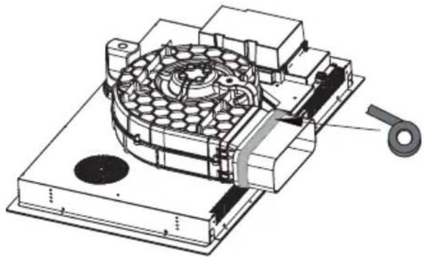
natural_image
Technical illustration of a mechanical device with internal components and a handle (no text or symbols)
natural_image
Architectural line drawing of a building facade with structural components and a diagonal roof (no text or symbols)
natural_image
Architectural cross-section diagram of a building interior with structural beams and internal components (no text or labels)Achtung!
natural_image
Technical diagram showing a mechanical assembly with a bolt and directional arrow (no text or labels)SCHALTPLAN:
Versorgungsspannung
AC220-240V 50/60Hz
AC380-415V
3N\~
50/60Hz
natural_image
Pure technical line drawing of a mechanical part (no text or symbols)
text_image
1 90° 176,5135,5

text_image
R20 222 89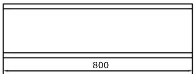
text_image
8002

natural_image
Simple line drawing of a rectangular prism (no text or symbols)3
text_image
R18 306 66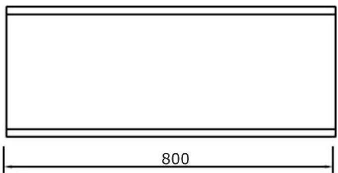
text_image
800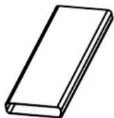
natural_image
Simple line drawing of a rectangular block (no text or symbols)5

text_image
10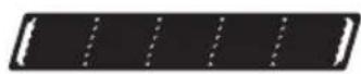
4
text_image
74 396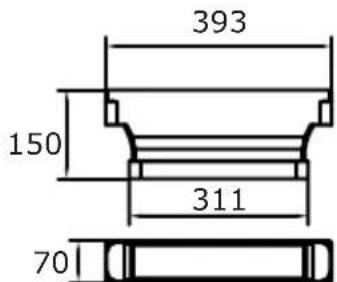
text_image
393 150 311 70
BEDIENUNG
Ihr Gerät
flowchart
graph TD
    A["Region 1"] --> B["Process Block"]
    C["Region 2"] --> B
    D["Region 3"] --> B
    B --> E["Output"]
    style A fill:#f9f,stroke:#333
    style C fill:#f9f,stroke:#333
    style D fill:#f9f,stroke:#333
text_image
Diagram showing two hand-drawn checkmark and cross symbols, likely indicating correct and incorrect actions.natural_image
Technical line drawing of a mechanical assembly with no visible text or symbols
natural_image
Technical line drawing of a mechanical assembly with no visible text or symbols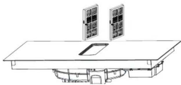
natural_image
Technical line drawing of a solar panel installation with two panels mounted on a base (no text or symbols)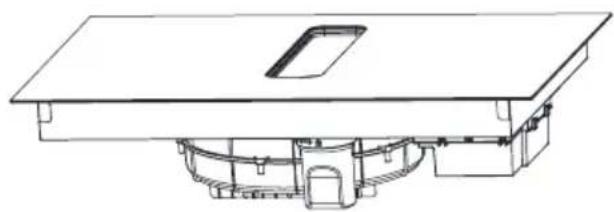
natural_image
Technical line drawing of a mechanical assembly with no visible text or symbolsGARANTIE, NACHVERKAUFSERVICE
Garantie
natural_image
Recycling symbol composed of three chasing arrows forming a triangle (no text or labels)natural_image
Symbol of a trash bin crossed with a diagonal line, no text or numbers presentnatural_image
Simple black-and-white line drawing of a tree with cloud-like canopy and two wavy lines below (no text or symbols)natural_image
Illustration of a cooking pot with three circular kitchen utensils, no text or symbols presentnatural_image
Simple line drawing of a cooking pot with crossed-out X symbol (no text or labels)
natural_image
Simple line drawing of a cooking pot with crossed X-shaped panes (no text or symbols)
natural_image
Simple line drawing of a cooking pot with crossed-out X marks (no text or symbols)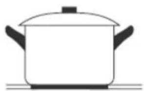
natural_image
Simple line drawing of a cooking pot on a stove (no text or symbols)natural_image
Diagram of a cooking pot with crossed arrows indicating pressure or flow (no text or symbols)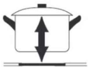
natural_image
Simple line drawing of a cooking pot with upward and downward arrows indicating direction (no text or symbols)text_image
Image showing a circled checkmark symbol inside a circle on a grid background.
natural_image
Empty rounded rectangle shape with no text or symbols
text_image
Image showing a circle with a 'X' symbol and a dot pattern in the background, likely indicating cancellation or error.
natural_image
Technical illustration of a mechanical assembly with labeled components and directional arrows (no text or symbols)natural_image
Technical line drawing of a mechanical assembly with dimension label B (no text or symbols beyond basic geometry)natural_image
Technical line drawing of a mechanical assembly with no visible text or symbols
natural_image
Technical line drawing of a mechanical assembly with no visible text or symbols
text_image
Y X MIN 220 ≥70
text_image
834 750 130,5 125 240 110natural_image
Technical line drawing of a mechanical assembly with no visible text or symbolsnatural_image
Technical illustration of a mechanical assembly with a central gear-like component and directional arrows indicating motion (no text or symbols)natural_image
Technical line drawing of a mechanical assembly with internal components and mounting base (no text or symbols)
natural_image
Technical illustration of a mechanical device with internal components and a handle (no text or symbols)
natural_image
Architectural line drawing of a building facade with structural elements and a diagonal roof (no text or symbols)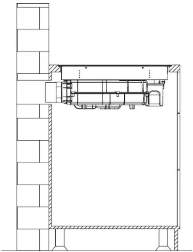
natural_image
Architectural cross-section diagram of a building interior with structural beams and internal components (no text or labels)Pozor!
natural_image
Technical drawing of a mechanical assembly with hatched areas and a bolt, showing no text or symbolsELEKTRICKÉ SCHÉMA
Napájecí napětí
AC220-240V 50/60Hz
AC380-415V
3N\~
50/60Hz
Celkový výkon
7,58kW
Elektrické schéma:
natural_image
Pure technical line drawing of a mechanical part (no text or symbols)
text_image
1 90° 176,5135,5

text_image
R20 222 89
text_image
8002

natural_image
Simple line drawing of a rectangular prism (no text or symbols)3

text_image
R18 306 66
text_image
800
natural_image
Simple line drawing of a rectangular book or document (no text or symbols visible)5

text_image
10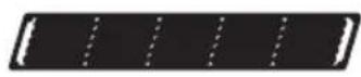
4

text_image
74 396
text_image
393 150 311 70
OVLÁDÁNÍ
Vaše zařízení

flowchart
graph TD
    A["1"] --> B["2"]
    C["2"] --> D["3"]
    B --> E["Processing Block"]
    D --> E
    style A fill:#f9f,stroke:#333
    style C fill:#f9f,stroke:#333
    style B fill:#ccf,stroke:#333
    style D fill:#ccf,stroke:#333
text_image
Cropped image showing a sequence of symbols and numbers, possibly representing data or logic instructions.text_image
Diagram showing two hand-drawn checkmark and cross symbols, likely indicating correct and incorrect conditions.natural_image
Technical line drawing of a mechanical assembly with no visible text or symbols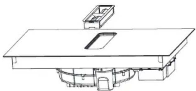
natural_image
Technical line drawing of a mechanical assembly with no visible text or symbols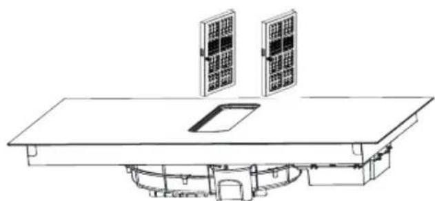
natural_image
Line drawing of a solar panel installation with two panels mounted on a table (no text or symbols)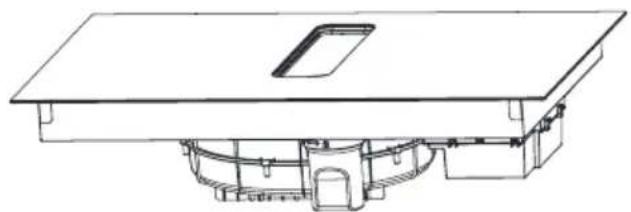
natural_image
Technical line drawing of a mechanical assembly with no visible text or symbolsČištění mřížky
natural_image
Recycling symbol composed of three chasing arrows forming a triangle (no text or labels)natural_image
Symbol of a trash bin crossed with a diagonal line, no text or numbers presentnatural_image
Simple black-and-white line drawing of a tree with cloud-like canopy and two wavy lines below (no text or symbols)natural_image
Illustration of a cooking pot with three circular kitchen utensils, no text or symbols presentnatural_image
Simple line drawing of a cooking pot with crossed-out X symbol (no text or labels)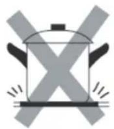
natural_image
Simple line drawing of a cooking pot with crossed X-shaped panes (no text or symbols)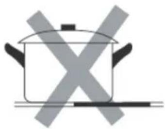
natural_image
Simple line drawing of a cooking pot with crossed-out X marks (no text or symbols)
natural_image
Simple line drawing of a cooking pot on a stove (no text or symbols)natural_image
Diagram of a cooking pot with crossed arrows indicating pressure or flow (no text or symbols)
natural_image
Simple line drawing of a cooking pot with upward and downward arrows indicating pressure or direction (no text or symbols)text_image
Image showing a circled checkmark symbol inside a circle on a grid background.
natural_image
Empty rounded rectangle shape with no text or symbols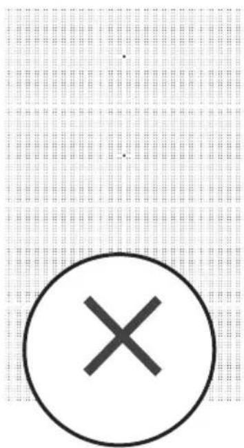
text_image
Image showing a circle with a 'X' symbol and a dot pattern in the background, likely indicating cancellation or error.
natural_image
Technical line drawing of a mechanical assembly with no visible text or symbolsnatural_image
Technical line drawing of a mechanical assembly with no visible text or symbols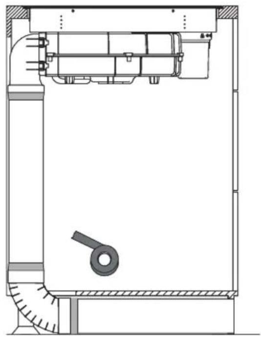
natural_image
Technical line drawing of a mechanical assembly with no visible text or symbols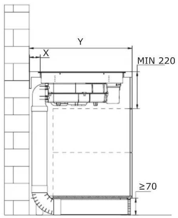
text_image
Y X MIN 220 ≥70
text_image
834 750 130,5 125 240 110natural_image
Technical line drawing of a mechanical assembly with no visible text or symbolsnatural_image
Technical illustration of a mechanical assembly with a hexagonal component and directional arrows indicating motion (no text or symbols)natural_image
Technical line drawing of a mechanical assembly with internal components and mounting base (no text or symbols)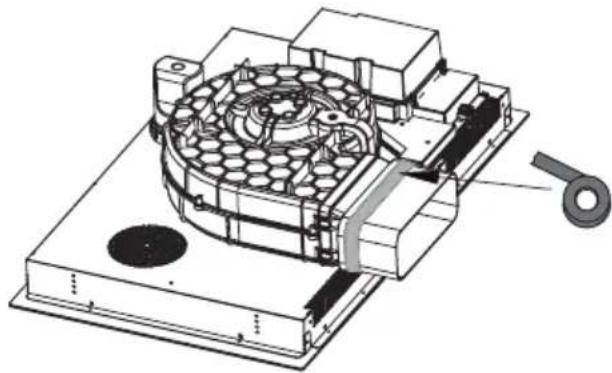
natural_image
Technical illustration of a mechanical device with internal components and a handle (no text or symbols)
natural_image
Architectural line drawing of a building facade with structural elements and a diagonal roof (no text or symbols)
natural_image
Architectural cross-section diagram of a building interior with structural beams and internal components (no text or labels)Pozor!
natural_image
Technical drawing of a mechanical assembly with hatched areas and a bolt, showing no text or symbolsELEKTRICKÁ SCHÉMA
El. napätie zdroja AC220-240V 50/60Hz
AC 380 - 415 V 3N\~ 50/60 Hz
natural_image
Pure technical line drawing of a mechanical part (no text or symbols)
text_image
1 90° 176,5135,5
text_image
R20 222 89
text_image
8002

natural_image
Simple line drawing of a rectangular prism (no text or symbols)3
text_image
R18 306 66
text_image
800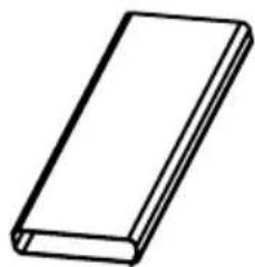
natural_image
Simple line drawing of a rectangular book or document (no text or symbols visible)5
text_image
10
4
text_image
74 396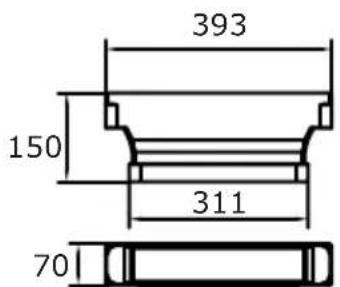
text_image
393 150 311 70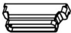
POUŽÍVANIE:
Vaše zariadenie
flowchart
graph TD
    A["Section 1"] --> B["Process Block"]
    C["Section 2"] --> B
    D["Section 3"] --> B
    B --> E["Output"]
    style A fill:#f9f,stroke:#333
    style C fill:#f9f,stroke:#333
    style D fill:#f9f,stroke:#333
text_image
Cropped image showing a sequence of symbols and numbers, possibly representing data or logic instructions.text_image
Diagram showing two hand-drawn checkmark and cross symbols on a line, likely indicating correct and incorrect actions.natural_image
Recycling symbol composed of three chasing arrows forming a triangle (no text or labels)natural_image
Symbol of a trash bin crossed with a diagonal line, no text or numbers presentnatural_image
Simple black-and-white line drawing of a tree with cloud-like canopy and two wavy lines below (no text or symbols)natural_image
Illustration of three kitchen utensils: a large pot, two circular plates with perforated surfaces, and a circular fan with a dot pattern (no text or symbols)natural_image
Two cooking pots with crossed arrows indicating heating or cooling conditions (no text or symbols)text_image
Diagram showing checkmark and cross symbols on a grid background, likely for verification or validation.natural_image
Technical illustration of a mechanical assembly with a central hexagonal component and directional arrows indicating motion (no text or symbols)natural_image
Technical line drawing of a mechanical assembly with no visible text or symbols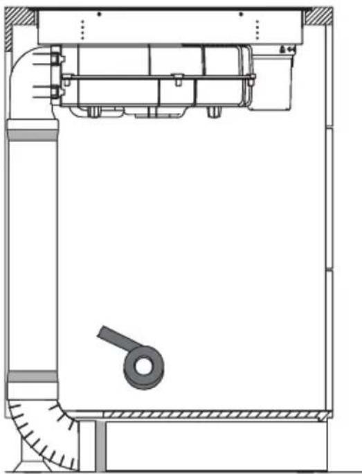
natural_image
Technical line drawing of a mechanical assembly with no visible text or symbols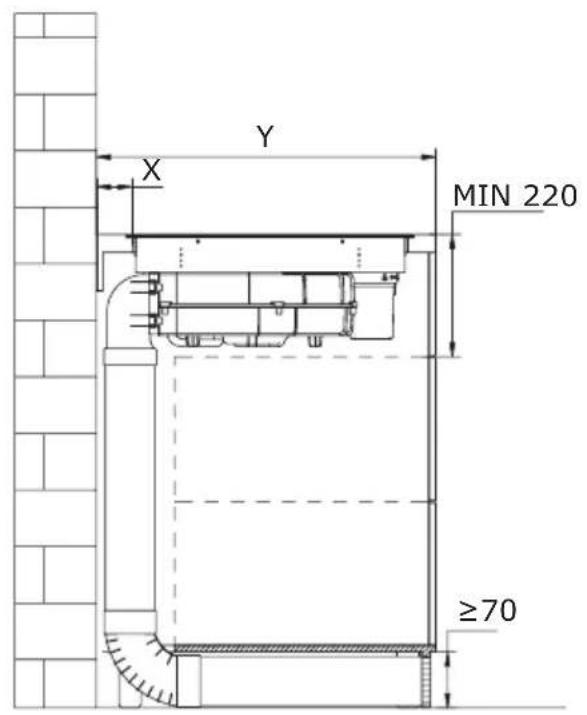
text_image
Y X MIN 220 ≥70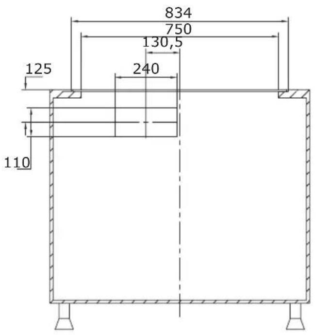
text_image
834 750 130,5 240 125 110natural_image
Technical line drawing of a mechanical assembly with no visible text or symbolsnatural_image
Technical line drawing of a mechanical assembly with no visible text or symbolsnatural_image
Technical line drawing of a mechanical assembly with internal components and mounting base (no text or symbols)
natural_image
Technical illustration of a mechanical device with internal components and a handle (no text or symbols)
natural_image
Architectural line drawing of a building facade with structural elements and a diagonal roof (no text or symbols)
natural_image
Architectural cross-section diagram of a building interior with structural beams and internal components (no text or labels)Attention!
natural_image
Technical diagram showing a mechanical assembly with a bolt and directional arrow (no text or labels)SCHÉMA ÉLECTRIQUE
Napięcie zasilania
AC220-240V 50/60Hz
AC380-415V
3N\~
50/60Hz
Puissance totale
7,58kW
Schéma électrique :
| Tension Raccordement électrique | Schéma des raccordements | Câble d'alimentation | |
| 220-240 V~ | 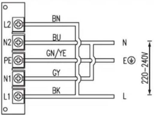 |  | 5G 2,5mm2 H07RN-F L1:BK L2:BN N1:GY N2:BU PE:GN/YE |
| 380-415 V~ |  | 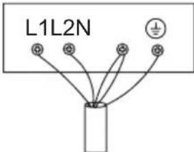 | 5G2.5mm2 H07RN-F L1:BK L2:BN N1:GY N2:BU PE:GN/YE |
| L1, L2 = Phase N1, N2 = Neutre PE = Mise à la terre | |||
KIT DE CONDUITS POUR PLAQUE À INDUCTION AVEC EXTRACTEUR
natural_image
Pure technical line drawing of a mechanical part (no text or symbols)
text_image
1 90° 176,5135,5

text_image
R20 222 89
text_image
8002

natural_image
Simple line drawing of a rectangular prism (no text or symbols)3

text_image
R18 306 66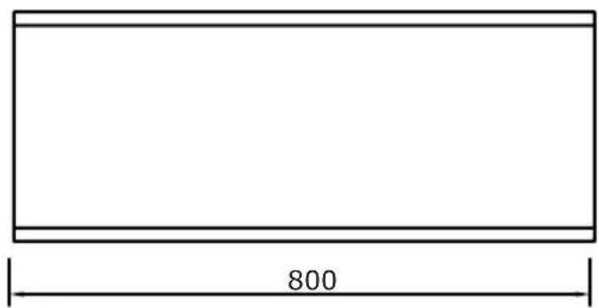
text_image
800
natural_image
Simple line drawing of a rectangular book or document (no text or symbols visible)5
text_image
10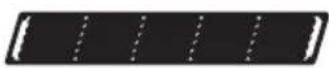
4

text_image
74 396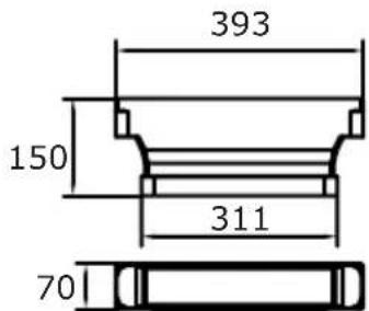
text_image
393 150 311 70
FONCTIONNEMENT
Votre appareil

flowchart
graph TD
    A["1"] --> B["Process Block"]
    C["2"] --> B
    D["3"] --> B
    B --> E["Output"]
    style B fill:#f9f,stroke:#333
    style E fill:#ccf,stroke:#333
text_image
Diagram showing two hand-drawn checkmark and cross symbols, likely indicating correct and incorrect actions.natural_image
Technical line drawing of a mechanical assembly with no visible text or symbols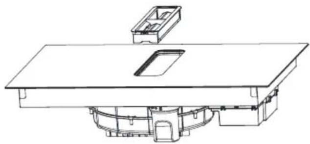
natural_image
Technical line drawing of a mechanical assembly with no visible text or symbols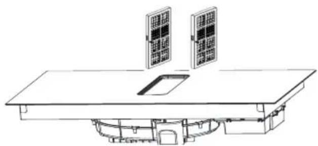
natural_image
Technical line drawing of a solar panel installation with two panels mounted on a base (no text or symbols)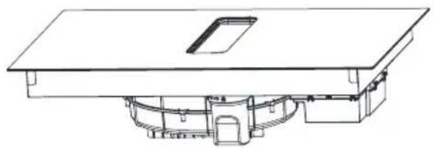
natural_image
Technical line drawing of a mechanical assembly with no visible text or symbolsnatural_image
Recycling symbol composed of three chasing arrows forming a triangle (no text or labels)natural_image
Simple line drawing of a trash bin with no text or symbolsnatural_image
Simple black-and-white line drawing of a tree with cloud-like canopy and two wavy lines below (no text or symbols)BASISINFORMATIE OVER HET APPARAAT
natural_image
Illustration of a cooking pot with three circular kitchen utensils, no text or symbols presentnatural_image
Simple line drawing of a cooking pot with crossed-out X symbol (no text or labels)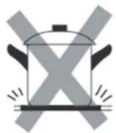
natural_image
Simple line drawing of a cooking pot with X-shaped marks and steam lines (no text or symbols)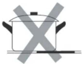
natural_image
Simple line drawing of a cooking pot with crossed-out X symbol (no text or labels)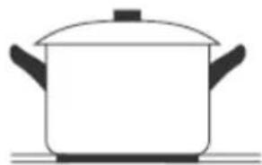
natural_image
Simple line drawing of a cooking pot with lid and side handles (no text or symbols)natural_image
Simple line drawing of a cooking pot with crossed arrows indicating pressure or resistance (no text or symbols)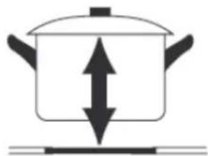
natural_image
Simple line drawing of a cooking pot with upward and downward arrows indicating direction (no text or symbols)text_image
Image showing a black checkmark inside a circle on a grid background
natural_image
Empty rectangular frame with rounded corners (no text or symbols)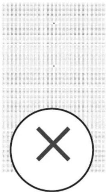
text_image
Image showing a circle with a 'X' symbol and a dot above it, set against a dotted grid background.Restwarmte-indicator "H"
INFORMATIE VOORAFGAAND
AAN DE INSTALLATIE
natural_image
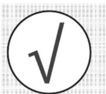
Technical illustration of a mechanical assembly with labeled components and directional arrows (no text or symbols)text_image
1000 A=H-345 A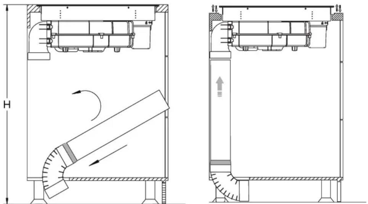
natural_image
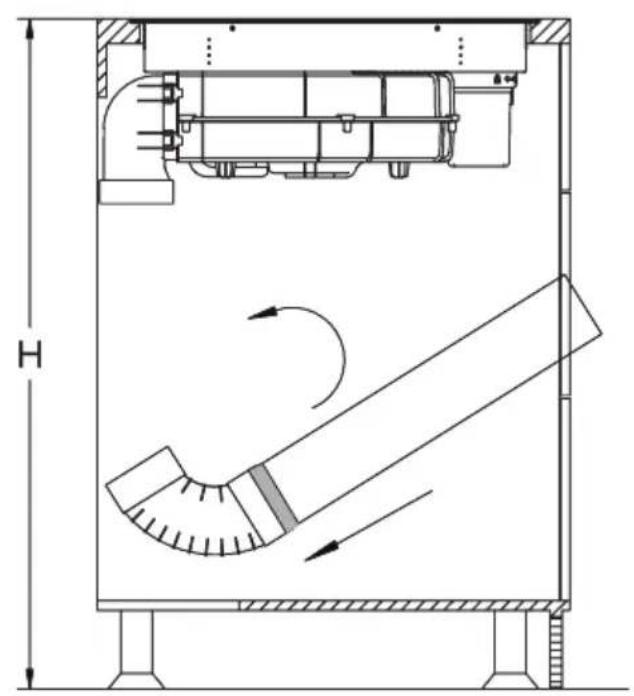
Technical schematic of a mechanical device with cross-sectional views and internal airflow indicators (no text or symbols)natural_image
Technical line drawing of a mechanical assembly with dimension label B (no text or symbols beyond basic geometry)natural_image
Technical line drawing of a mechanical assembly with no visible text or symbols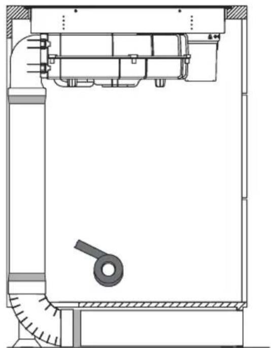
natural_image
Technical line drawing of a mechanical assembly with no visible text or symbols
text_image
Y X MIN 220 ≥70
text_image
834 750 130,5 125 240 110natural_image
Technical line drawing of a mechanical assembly with no visible text or symbolsnatural_image
Technical illustration of a mechanical assembly with a housing, rotor, and mounting bracket (no text or symbols)natural_image
Technical line drawing of a mechanical assembly with internal components and mounting base (no text or symbols)
natural_image
Technical illustration of a mechanical device with internal components and a handle (no text or symbols)
natural_image
Architectural line drawing of a building facade with structural elements and a diagonal roof (no text or symbols)
natural_image
Architectural cross-section diagram of a building facade with structural supports and internal components (no text or labels)Opgelet!
natural_image
Technical diagram showing a mechanical assembly with a bolt and directional arrow (no text or labels)ELEKTRISCH SCHEMA
INDUCTIEKOOKPLAAT MET
AFZUIGER
natural_image
Pure technical line drawing of a mechanical part (no text or symbols)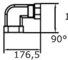
text_image
1 90° 176,5135,5

text_image
R20 222 89
text_image
8002

natural_image
Simple line drawing of a rectangular prism (no text or symbols)3
text_image
R18 306 66
text_image
800
natural_image
Simple line drawing of a rectangular book or document (no text or symbols visible)5

text_image
10
4
text_image
74 396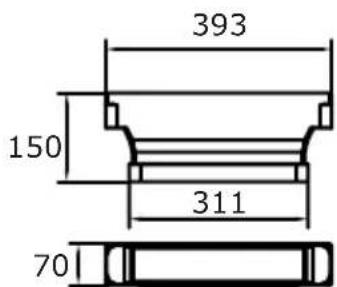
text_image
393 150 311 70
BEDIENING
Uw apparaat

flowchart
graph TD
    A["1"] --> B["Process Block"]
    C["2"] --> B
    D["3"] --> B
    B --> E["Output"]
    style B fill:#f9f,stroke:#333
    style E fill:#ccf,stroke:#333
text_image
Cropped image showing a sequence of symbols and numbers, possibly representing data or logic instructions.text_image
Diagram showing two hand-drawn checkmark and cross symbols, likely indicating correct and incorrect conditions.natural_image
Technical line drawing of a mechanical assembly with no visible text or symbols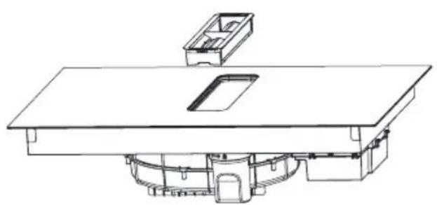
natural_image
Technical line drawing of a mechanical assembly with no visible text or symbols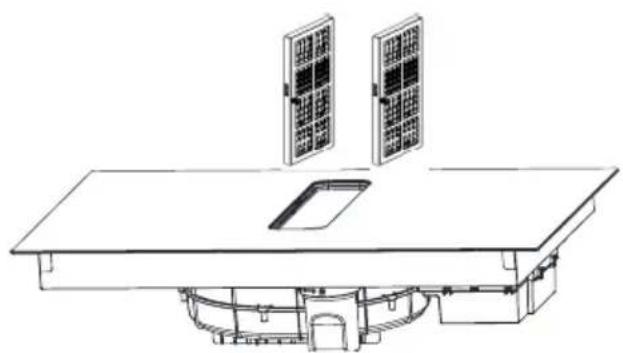
natural_image
Technical line drawing of a solar panel installation with two panels mounted on a table (no text or symbols)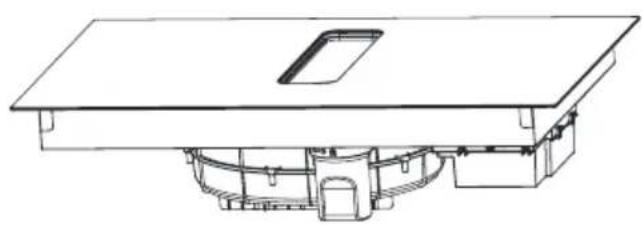
natural_image
Technical line drawing of a mechanical assembly with no visible text or symbolsnatural_image
Recycling symbol composed of three chasing arrows forming a triangle (no text or labels)natural_image
Symbol of a trash bin crossed with a diagonal line, no text or numbers presentnatural_image
Simple black-and-white line drawing of a tree with cloud-like canopy and two wavy lines below (no text or symbols)- Osoba koja troši energiju na odgovoran način štiti ne samo kućni proračun, ali i svjesno brine za okoliš. Zato pomozimo, štedimo električnu energiju! To činimo na sljedeći način:
- Uporaba pravilnih posuda za kuhanje.
- Posude s ravnim i debelim dnom omogućavaju štednju do 1/3 električne energije. Uvijek treba stavljati poklopac jer se inače povećava potrošnja električne energije.
-
Briga za čistoću grijaćih polja i dna posuda.
-
Zaprljanja ograničavaju predavanje topline – tvrdokorne nečistoće često uklanjamo samo sredstvima koja ozbiljno narušavaju okoliš.
- Izbjegavati nepotrebno „zavirivanje u posude“.
- Ne ugrađivati pećnicu u neposrednoj blizini hladnjaka/zamrzivača. Ovi uređaji nepotrebno povećavaju potrošnju električne energije
OSNOVNE INFORMACIJE O UREĐAJU
natural_image
Illustration of a cooking pot with three circular kitchen utensils, no text or symbols presentnatural_image
Diagram of a cooking pot with crossed arrows indicating pressure or flow direction (no text or symbols)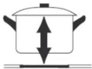
natural_image
Simple line drawing of a cooking pot with upward and downward arrows indicating direction (no text or symbols)- Kada koristite proizvod, pogledajte donju ilustraciju za pravilno postavljanje posude. Lonac treba staviti na mjesto označeno na staklu.
text_image
Image showing a circled checkmark symbol inside a circle on a grid background.
natural_image
Empty rectangular frame with rounded corners (no text or symbols)
text_image
Image showing a circle with an 'X' symbol and a dot pattern in the background, likely indicating cancellation or error.
Pokazatelj preostale topline „H”
natural_image
Technical illustration of a mechanical assembly with labeled components and directional arrows (no text or symbols)Stavite proizvod na radnu ploču i prilagodite ga.

text_image
MIN 220 470 ≥70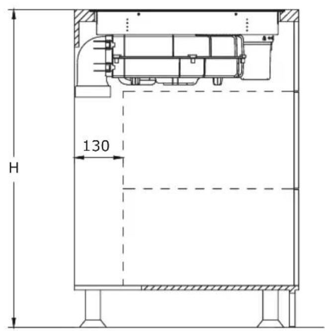
text_image
H 130Za učinkovitu recirkulaciju preporučujemo instalaciju seta cijevi za indukcijsku ploču s ispušnim sustavom. Ovaj set možete kupiti zasebno pod nazivom PSD 100 DOWNAIR SET. U nastavku se nalazi pregled pojedinih uključenih komponenti. Odgovarajuće dimenzije nalaze se u poglavlju „Set cijevi za indukcijsku ploču s ispušnim sustavom”.
natural_image
3D diagram of a rectangular prism with labeled point B and dashed line indicating a dimension (no text or symbols beyond label)Primijenite priloženu brtvenu traku na sve spojeve, slijedeći upute na slikama.
natural_image
Technical line drawing of a mechanical assembly with no visible text or symbols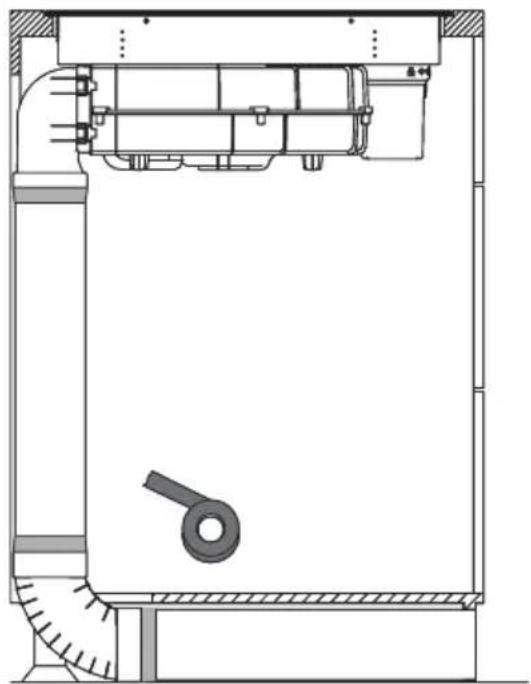
natural_image
Technical line drawing of a mechanical assembly with no visible text or symbols
text_image
Y X MIN 220 ≥70
text_image
834 750 130,5 125 240 110natural_image
Technical line drawing of a mechanical assembly with no visible text or symbolsStavite proizvod na radnu ploču i prilagodite ga.
text_image
MIN 220 470 ≥70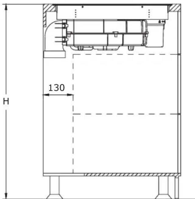
text_image
H 130Za to koristite komponente iz seta cijevi PSD 100 DOWNAIR SET za indukcijsku ploču s ispušnim sustavom, koji se mora kupiti zasebno.
Metoda 2
Ugradite spremnik za vodu okretanjem u odgovarajućem smjeru kao što pokazuje strelica. Zatim postavite priloženu gumenu brtvu na mjesto označeno strelicom na slici ispod. Na kraju, pričvrstite konektor u rupu prikazanu na slici, pazeći da ispravno pristaje.
natural_image
Technical line drawing of a mechanical assembly with no visible text or symbolsnatural_image
Technical line drawing of a mechanical assembly with internal components and mounting base (no text or symbols)
natural_image
Technical illustration of a mechanical device with internal components and a handle (no text or symbols)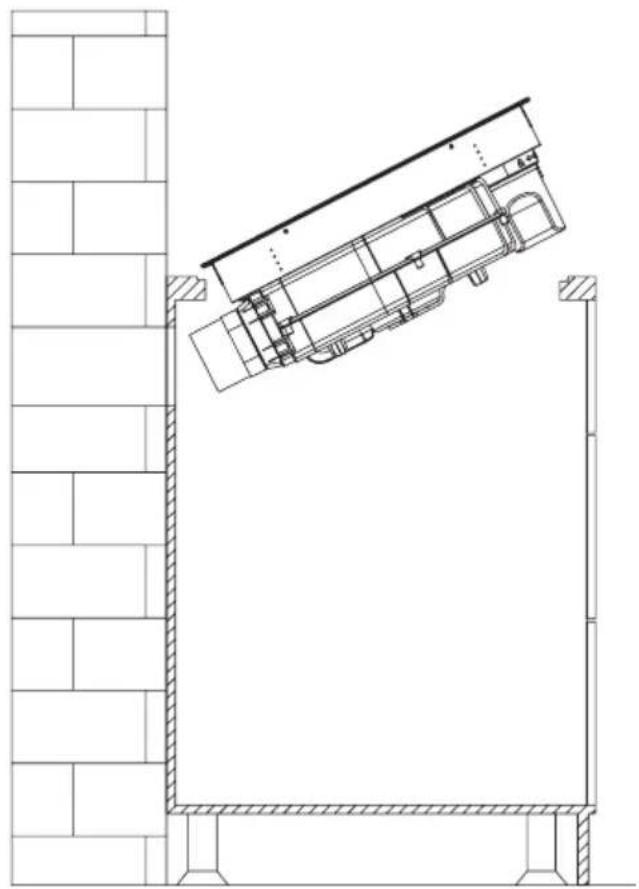
natural_image
Architectural line drawing of a building facade with structural elements and a diagonal roof (no text or symbols)
natural_image
Architectural cross-section diagram of a building interior with structural beams and internal components (no text or labels)Pozor!
natural_image
Technical drawing of a mechanical assembly with hatched areas and a bolt, showing no text or symbolsELEKTRIČNA ŠHEMA
Napona napajanja AC220-240V 50/60Hz
AC380-415V
3N\~
50/60Hz
Ukupna snaga 7,58kW
Električna shema:
| Napon Električni priključak | Dijagram povezivanja | Kabel za napajanje | |
| 220-240 V~ | | | 5G 2,5mm2 H07RN-F L1:BK L2:BN N1:GY N2:BU PE:GN/YE |
| 380-415 V~ | 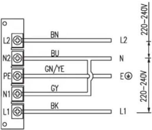 | | 5G2.5mm2 H07RN-F L1:BK L2:BN N1:GY N2:BU PE:GN/YE |
| L1, L2 = faza N1, N2 = neutralni PE = uzemljenje | |||
SET CIJEVI ZA INDUKCIJSKU PLOČU S ISPUŠNIM SUSTAVOM
natural_image
Pure technical line drawing of a mechanical part (no text or symbols)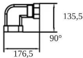
text_image
135,5 90° 176,5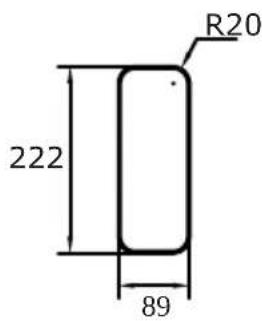
text_image
R20 222 89
text_image
8002

natural_image
Simple line drawing of a rectangular prism (no text or symbols)3

text_image
R18 306 66
text_image
800
natural_image
Simple line drawing of a rectangular book or document (no text or symbols visible)5

text_image
10
4
text_image
74 396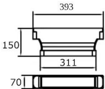
text_image
393 150 311 70
UPORABA
Vaš uređaj

flowchart
graph TD
    A["1"] --> B["Process Block"]
    C["2"] --> B
    D["3"] --> B
    B --> E["Output"]
    style A fill:#f9f,stroke:#333
    style C fill:#f9f,stroke:#333
    style D fill:#f9f,stroke:#333
- Ulaz za ventilaciju kuhinjske nape
- Indukcijsko grijaće polje booster
- Kontrolna ploča na dodir
Upravljačka ploča
text_image
Cropped image showing a sequence of symbols and numbers, possibly representing data or logic instructions.Vaš uređaj je opremljen upravljačkom pločom na dodir:
- Uvjerite se da su kontrole uvijek čiste, suhe i da ih nikakav predmet (poput posude ili krpe) ne prekriva. Čak i tanak sloj vode može otežati upravljanje kontrolama.
- Kontrole na vašem uređaju su osjetljive na dodir, tako da nema potrebe za primjenom pritiska.
- Svaki put kada se dogodi dodir, čut ćete zvučni signal.
- Koristite prst, a ne samo vrh.
text_image
Diagram showing two hand-drawn checkmark and cross symbols on a line, likely indicating correct and incorrect conditions.natural_image
Technical line drawing of a mechanical assembly with no visible text or symbolsČišćenje rešetke
Uklonite rešetku i očistite je kr- pom i blagim tekućim deterdžen- tom. Izbjegavajte korištenje proizvoda koji sadrže abrazivne tvari.
natural_image
Technical line drawing of a mechanical assembly with no visible text or symbolsČišćenje Masnog Filtara
natural_image
Line drawing of a simple architectural or mechanical setup with two solar panels mounted above a table (no text or symbols)natural_image
Technical line drawing of a mechanical assembly with no visible text or symbolsČišćenje spremnika za vodu
natural_image
Recycling symbol composed of three chasing arrows forming a triangle (no text or labels)natural_image
Symbol of a trash bin crossed with a diagonal line, no text or numbers presentnatural_image
Simple black-and-white line drawing of a tree with cloud-like canopy and two wavy lines below (no text or symbols)natural_image
Illustration of a cooking pot with three circular kitchen utensils, no text or symbols presentnatural_image
Diagram of a cooking pot with crossed arrows indicating pressure or flow (no text or symbols)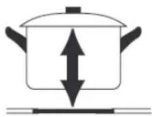
natural_image
Simple line drawing of a cooking pot with upward and downward arrows indicating pressure or direction (no text or symbols)text_image
Two circled icons: a checkmark inside a circle and a cross inside a circle, placed on a grid background.Indikator preostale toplote „H“
natural_image
Technical line drawing of a mechanical assembly with no visible text or symbolsIzdelek namestite na pult in ga poravnajte.

text_image
MIN 220 470 ≥70
text_image
H 130natural_image
3D diagram of a rectangular prism with labeled point B and dashed line indicating a dimension (no text or symbols beyond label)natural_image
Technical line drawing of a mechanical assembly with no visible text or symbols
natural_image
Technical line drawing of a mechanical assembly with no visible text or symbols
text_image
Y X MIN 220 ≥70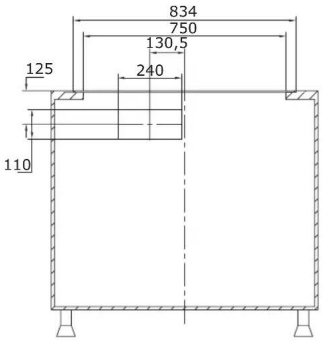
text_image
834 750 130,5 125 240 110natural_image
Technical line drawing of a mechanical assembly with no visible text or symbolsIzdelek namestite na pult in ga poravnajte.

text_image
MIN 220 470 ≥70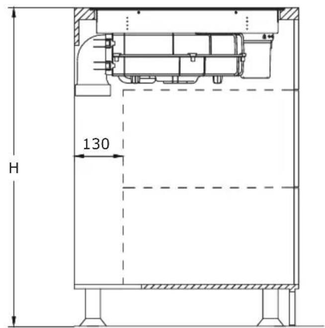
text_image
H 130natural_image
Technical line drawing of a mechanical assembly with no visible text or symbolsnatural_image
Technical line drawing of a mechanical assembly with internal components and mounting base (no text or symbols)
natural_image
Technical illustration of a mechanical device with internal components and a handle (no text or symbols)
natural_image
Architectural line drawing of a building facade with structural elements and a diagonal roof (no text or symbols)
natural_image
Architectural cross-section diagram of a building interior with structural beams and internal components (no text or labels)Pozor!
natural_image
Technical drawing of a mechanical assembly with hatched areas and a bolt, showing no text or symbolsELEKTRIČNI DIAGRAM:
Napetost napajanja AC220-240V 50/60Hz
AC380-415V
3N\~
50/60Hz
Skupna moč 7,58 kW
Električni diagram:
| Napetost Električna povezava Shema povezav | Napajalni kabel | ||
| 220-240 V~ | | 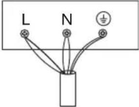 | 5G 2,5mm2 H07RN-F L1:BK L2:BN N1:GY N2:BU PE:GN/YE |
| 380-415 V~ | | | 5G2.5mm2 H07RN-F L1:BK L2:BN N1:GY N2:BU PE:GN/YE |
| L1, L2 = Faza N1, N2 = Nevtralni PE = Ozemljitev | |||
KOMPLET CEVI ZA INDUKCIJSKO KUHALNO PLOŠČO Z IZVLEČNIKOM
natural_image
Pure technical line drawing of a mechanical part (no text or symbols)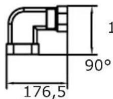
text_image
1 90° 176,5135,5

text_image
R20 222 89
text_image
8002
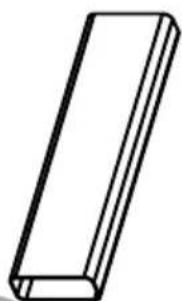
natural_image
Simple line drawing of a rectangular prism (no text or symbols)3
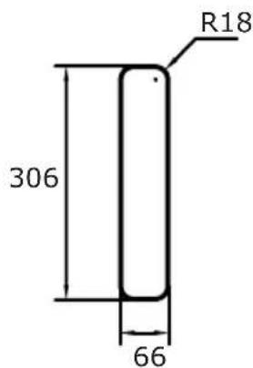
text_image
R18 306 66
text_image
800
natural_image
Simple line drawing of a rectangular block (no text or symbols)5

text_image
10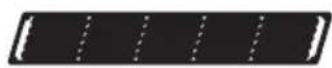
4
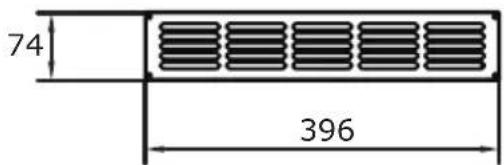
text_image
74 396
text_image
393 150 311 70
UPRAVLJANJE
Vaša naprava

flowchart
graph TD
    A["Section 1"] --> B["Process Block"]
    C["Section 2"] --> B
    D["Section 3"] --> B
    B --> E["Output"]
    style A fill:#f9f,stroke:#333
    style C fill:#f9f,stroke:#333
    style D fill:#f9f,stroke:#333