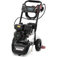
Hillvert HT-HPW-180 - Pressure washer

HT-HPW-180 - Pressure washer Hillvert - Free user manual and instructions

Find the device manual for free HT-HPW-180 Hillvert in PDF.

📄 250 pages English EN Download 💬 AI Question
Notice Hillvert HT-HPW-180 - page 31
Pick your language and provide your email: we'll send you a specifically translated version.

User questions about HT-HPW-180 Hillvert

0 question about this device. Answer the ones you know or ask your own.

Ask a new question about this device

The email remains private: it is only used to notify you if someone responds to your question.

No questions yet. Be the first to ask one.

Download the instructions for your Pressure washer in PDF format for free! Find your manual HT-HPW-180 - Hillvert and take your electronic device back in hand. On this page are published all the documents necessary for the use of your device. HT-HPW-180 by Hillvert.

USER MANUAL HT-HPW-180 Hillvert
text_image Labeled diagram of a power saw with numbered parts for identification
text_image A B C D E F G
natural_image Close-up of a hand using a screwdriver to adjust a mechanical component with an arrow indicating rotation (no text or symbols visible)
natural_image Close-up of a hand adjusting a black tire on a motorcycle wheel (no visible text or symbols)
natural_image 3D rendered mechanical component resembling a valve or connector (no text or symbols visible)
natural_image Black and white photo of a car steering wheel (no visible text or symbols)
natural_image Close-up of a mechanical device with attached components, showing a close-up inset (no visible text or symbols)
natural_image Close-up of a mechanical device with no visible text or symbols

Hillvert HT-HPW-180 - 1

natural_image Close-up of a hand holding a small electronic component with a metallic shaft (no visible text or symbols)
natural_image Close-up of a mechanical assembly with bolts and components (no visible text or symbols)

Hillvert HT-HPW-180 - 2

natural_image Close-up of a hand using a tool to adjust or install a mechanical component, labeled 'A' with no visible text or symbols beyond the label.
natural_image Close-up of hands holding a small mechanical component, possibly a tool or device (no visible text or symbols)
natural_image Close-up of a hand adjusting a vehicle's wheel assembly (no visible text or symbols)
natural_image Close-up of a hand using a wrench to adjust a mechanical component, with no visible text or symbols.
natural_image Close-up of a hand adjusting a black tire on a motorcycle wheel (no visible text or symbols)
natural_image Black plastic roller or pulley device with mounting flanges and a central arrow indicator (no text or symbols)
natural_image Mechanical component with a close-up view of a cylindrical component labeled 'A', showing structural details and arrows (no text or symbols beyond label)
natural_image Close-up of a mechanical device with a rotating wheel and lever mechanism (no visible text or symbols)
natural_image Close-up of a mechanical device with a black lever and circular component (no visible text or symbols)
natural_image Close-up of hands assembling a bicycle wheel assembly with a screwdriver (no visible text or symbols)
natural_image Close-up of a mechanical component with no visible text or symbols

Hillvert HT-HPW-180 - 3

natural_image Close-up of a hand holding a small electronic component with a metallic shaft (no visible text or symbols)
natural_image Close-up of a mechanical assembly with bolts and a central component (no visible text or symbols)

Hillvert HT-HPW-180 - 4

natural_image Close-up of a hand using a tool to adjust or install an engine component, labeled 'A' with no visible text or symbols beyond the label.
natural_image Close-up of a hand holding small mechanical components, possibly a tool or component (no visible text or symbols)
natural_image Close-up of a hand adjusting automotive components with hoses and tools (no visible text or symbols)
natural_image Close-up of a hand holding a black spray gun, no visible text or symbols
natural_image Close-up of a black fuel pump nozzle with attached tubing (no visible text or symbols)
natural_image Close-up of a mechanical component with labeled parts (A and Z14) and no readable text or symbols beyond labels
natural_image Close-up of a gloved hand operating a mechanical device with a tool (no visible text or symbols)
natural_image Close-up of a hand operating a mechanical device with a white tool labeled 'D' (no readable text or symbols beyond the label)
natural_image Close-up of a hand holding a small white object into a cylindrical container, with a device and camera in the background (no visible text or symbols)
natural_image Close-up of a hand pressing a button on a black industrial control box (no visible text or symbols)
natural_image Close-up of a mechanical component with a red arrow pointing to a highlighted area, no visible text or symbols.

This User Manual has been translated for your convenience using machine translation. Reasonable efforts have been made to provide an accurate translation; however, no automated translation is perfect nor is it intended to replace human translators. The official User Manual is the English version. Any discrepancies or differences created in the translation are not binding and have no legal effect for compliance or enforcement purposes. If any questions arise related to the accuracy of the information contained in the User Manual, please refer to the English version of those contents which is the official version.

Technical Data

Parameter descriptionParameter value
Product nameGasoline high pressure cleaner
ModelHT-HPW-180HT-HPW-180A
Engine typeOHV 4-stroke 1-cylinder air-cooled, recoil starter
Displacement [cm3]212
Rated power [kW/hp]/rev. per minute4,5 / 7 / 3600
Fuel typeUnleaded gasoline 95+ octanes (RON)
Fuel tank capacity [L]3.5
Engine oil typeMineral or semi-synthetic SAE 10-15W30-40 * approx. 0.6 L for 4-stroke engines
* as a rule, 10W30 is sufficient for standard conditions in which the device is to operate
Pump oil typeGearbox SAE 80-85W90 GL4
Spark plug type / electrode gap [mm]F6TC* / 0,7-0,8
* or interchangeable equivalent
IP classIP 45
Dimensions [width x depth x height; mm]540 x 780 x 910 560 x 740 x 990
Weight [kg]3237
Hose length [m]820
Cleaning agent tank capacity [L]2.5 6
Maximum water pressure [MPa / bar]22 / 220
Rated Water Pressure (MPa)18 / 180
Maximum water flow [L/min.]10
Rated water flow [L/min.]8.5
Permissible water temperature [°C]1-60
Maximum water pressure in the connection [MPa / bar]20 / 200
Sound power level L_wA [dB] / guaranteed / Measurement uncertainty - K107.2 / 109 / K = 3
Sound pressure level L_pA [dB], measurement uncertainty - K93 / K = 3
Vibration emission level a h [m/s] / Measurement uncertainty - K≤2.5 / K = 2

1. General Description

The manual is intended to assist in safe and reliable use. The product is designed and manufactured strictly according to technical specifications using the latest technology and components and maintaining the highest quality standards.

CAREFULLY READ AND UNDERSTAND THIS MANUAL BEFORE STARTING THE WORK.

To ensure the long and reliable operation of the device, make sure to operate and maintain it properly following the guidelines in this instruction manual. The technical data and specifications in this manual are up-to-date. The manufacturer reserves the right to make changes to improve the quality. Taking the technical progress and the possibility of reducing noise into account, the unit is designed and built in such a way that risks resulting from noise emissions are reduced to the lowest possible level.

Explanation of symbols

CEThe product complies with applicable safety standards.
Hillvert HT-HPW-180 - Explanation of symbols - 1Read the manual before use.
Hillvert HT-HPW-180 - Explanation of symbols - 2Recyclable product.
Hillvert HT-HPW-180 - Explanation of symbols - 3CAUTION! or WARNING! or REMEMBER! describing a situation (general warning sign).
Hillvert HT-HPW-180 - Explanation of symbols - 4Wear ear protection. Exposure to noise may cause hearing loss.
Hillvert HT-HPW-180 - Explanation of symbols - 5Wear protective goggles.
Hillvert HT-HPW-180 - Explanation of symbols - 6Wear protective gloves.
Hillvert HT-HPW-180 - Explanation of symbols - 7Wear protective footwear.
Hillvert HT-HPW-180 - Explanation of symbols - 8CAUTION! Warning against loud noise!
Hillvert HT-HPW-180 - Explanation of symbols - 9CAUTION! Danger of fire - flammable material!
Hillvert HT-HPW-180 - Explanation of symbols - 10Warning against poisoning by toxic substances!
Hillvert HT-HPW-180 - Explanation of symbols - 11Caution! Hot surface can cause burns!
Hillvert HT-HPW-180 - Explanation of symbols - 12A suffocating atmosphere! Do not use in an unventilated space (risk of carbon monoxide poisoning)!
Hillvert HT-HPW-180 - Explanation of symbols - 13Do not smoke in the vicinity of the unit. The unit contains flammable substances.

Hillvert HT-HPW-180 - Explanation of symbols - 14

CAUTION! The figures in this manual are illustrative only and may vary in some details from the actual appearance of the product.

2. Safety of use

Hillvert HT-HPW-180 - Safety of use - 1

CAUTION! Read all safety warnings and instructions. Failure to follow warnings and actions could result in serious injury or even death.

The term "device" or "product" in the warnings and in the description of the instructions refers to:

Gasoline high pressure cleaner

2.1. Safety in the workplace

a) Keep the work area tidy and well-lit. Disorder or poor lighting can lead to accidents. Be foresighted, watch what you are doing, and use common sense when using the unit.
b) Do not use the unit in an explosive area, for example in the presence of flammable liquids, gases or dust. The unit produces sparks that can ignite dust or fumes.
c) If you find any damage or irregularities in the operation of the product, immediately turn it off and report it to an authorized person.
d) If you have any doubts as to whether the product is working properly or if it is damaged, contact the manufacturer's service department.
e) Repairs to the device may only be carried out by the manufacturer's service. Do not attempt to repair the product on your own!
f) In case of open flames or fire, use only dry powder or snow (CO2) fire extinguishers to extinguish the live equipment.
g) No children or unauthorized persons are allowed in the work area. (Inattention may result in loss of control of the unit.)
h) Use the unit in a well-ventilated area.
i) Dust and debris are generated during the operation of the device, please protect bystanders from their harmful effects.
j) Check the condition of the safety stickers regularly. Replace them if they are illegible.
k) Keep these instructions for use for future reference. If the product is to be handed over to a third party, hand it over with this user manual.
I) Keep packaging components and small installation parts out of the reach of children.
m) Keep the device away from children and animals.
n) When using this product together with other devices, also follow the other instructions for use.

Hillvert HT-HPW-180 - Safety in the workplace - 1

Remember! Keep children and other bystanders safe while operating the equipment.

2.2. Personal safety

a) Do not operate this device if you are tired, ill, or under the influence of alcohol, drugs, or medication that could impair your ability to operate the device.
b) The device is not intended to be used by persons (including children) with reduced mental, sensory, or intellectual functions or persons who lack experience and/or knowledge unless they are supervised or have been instructed by a person responsible for their safety on how to operate the device.
c) The unit may be operated by persons who are physically fit, capable of operating it, and appropriately trained, and who have read this instruction manual and have been trained in occupational safety and health.
d) Use caution and common sense when operating this unit. A moment's inattention during the operation may result in serious personal injury.
e) Use personal protective equipment as required when operating the unit as specified in Section 1 of the explanation of symbols. The use of appropriate, approved personal protective equipment reduces the risk of injury.
f) To prevent accidental start-up, make sure the switch is in the off position before connecting to a power source.
g) Do not overestimate your capabilities. Maintain body balance and equilibrium at all times during operation. This allows for better control of the machine in unexpected situations.
h) Do not wear loose clothing or jewelry. Keep hair, clothing, and gloves away from moving parts. Loose clothing, jewelry, or long hair can be caught in moving parts.
i) Before switching the unit on, remove any regulating tools or keys. Any tools or keys left in the rotating part of the unit may cause injury.
j) The product is not a toy. Children should be watched to ensure that they do not play with the product.
k) Do not place your hands or any objects inside the running device!

2.3. Safe use of the device

a) Do not overload the device. Use tools that are suitable for the application. A correctly selected product will do a better and safer job for which it was designed.

b) Do not use the device if the ON/OFF switch does not function properly (does not turn on and off). Units that cannot be controlled by the switch are unsafe, cannot operate, and must be repaired.
c) Disconnect the device from the power supply before adjusting, cleaning, or servicing. This precaution reduces the risk of accidental start-up.
d) Keep unused product out of the reach of children and anyone unfamiliar with the device or this manual. Products are dangerous when used by inexperienced users.
e) Keep the product in good working order. Check before each use for general damage or damage to moving parts (cracks in parts and components or any other condition that may affect the safe operation of the device). If damaged, return the device for repair before use.
f) Keep the product out of the reach of children.
g) Repairs and maintenance should be carried out by qualified personnel using only original spare parts. This will ensure the safety of use.
h) To ensure the designed operational integrity of the device, do not remove factory-installed covers or loosen screws.
i) When transporting or moving the device from storage to the place of use, observe the health and safety rules for manual handling applicable in the country where the device is used.
j) Avoid situations in which the device stops under heavy loads during operation. This can cause overheating of the drive elements and consequent damage to the equipment.
k) Do not leave the device switched on unattended.
I) Clean the device regularly to prevent permanent dirt build-up.
m) Before each use, make sure that the nozzle is properly mounted in the machine and that the hose is properly attached and undamaged.
n) Do not obstruct the air inlet or outlet.
o) The product is not a toy. Cleaning and maintenance must not be performed by children without adult supervision.
p) Do not start up an empty unit.
q) Do not tamper with the device to alter its performance or design.
r) Keep the unit away from sources of fire and heat.
s) Do not block the ventilation openings of the unit!
t) CAUTION! When cleaning or using the appliance, never immerse it in water or other liquids.
u) Do not use the appliance in rooms with very high humidity / in the immediate vicinity of water tanks!
v) Do not let the device get wet!
w) Protect the device from direct sunlight.
x) Maintain a safe distance between the working area of the device and bystanders.

y) Never aim the high-pressure nozzle at people, animals, electrical equipment or electrical wires. Doing so may cause personal injury or electrical shock.
z) Beware of the recoil phenomenon when using the high pressure washer gun. Always hold the high-pressure gun and nozzle with both hands.

aa) The device is designed to be used with a cleaning agent supplied or recommended by the manufacturer. The use of other cleaning agents may have an adverse effect on the safe use of the device.
bb) Clean vehicle tires from a minimum distance of 50 cm to avoid damage from the high-pressure jet!
cc) Add oil to the proper level before turning on the machine. If the oil level is too low the engine will not start or may shut down.
dd) Report any leakage of operating oils from the machine to the relevant authorities or comply with the legal requirements in your area of use.
ee) Danger! Health hazard and risk of explosion of the combustion engine.
ff) The engine exhausts contain poisonous carbon monoxide. Remaining in an environment containing carbon monoxide can lead to unconsciousness or even death. Do not run the engine in an enclosed area.
gg) Gasoline is flammable and explosive. Stop the engine and let it cool down before refueling.
hh) Caution! Wrong fuel may cause damage to the engine.
ii) CAUTION! Some parts of the device get hot during use! It is forbidden to touch hot components of the system during and after the immediate operation! Danger of burns!
jj) Caution! The HT-HPW-180 is not designed to be connected to a potable water supply!
kk) Make sure that the water used for pressure cleaning is free of any contamination,
II) Avoid dynamic switching on/off of the device!
mm) Caution! A high-pressure water jet can damage the surface being cleaned if the method of use is not correct. Always test the water jet first in an open area, and preferably on another surface that matches the structure of the one you intend to wash.
nn) Do not spray flammable substances with the device! Risk of explosion!
oo) Caution! Do not run the device without an air filter!
pp) Caution! In case of emergency shutdown: set the engine switch to the "OFF" position!

Hillvert HT-HPW-180 - Safe use of the device - 1

CAUTION! Although the product has been designed to be safe and has adequate safeguards and despite the additional safety features provided to the user, there is still a slight risk of accident or injury when handling the product. Caution and common sense are advised when using the product.

3. Instructions for use

The device is designed to help clean various objects and surfaces, especially in places where there is no access to electricity to use a traditional washer. The device can also draw water from an external tank.

The user is responsible for any damage resulting from misuse.

3.1. Product overview

HT-HPW-180
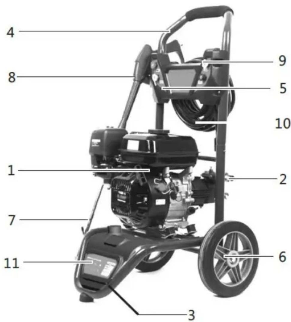
Hillvert HT-HPW-180 - Product overview - 1

text_image 4 8 1 7 11 3 6 2 10 5 9
  1. Motor
  2. Pump
  3. Lower frame

  4. Transport handle

  5. Control panel
  6. Circle (x2)
  7. Lance
  8. The gun
  9. Nozzle
  10. Reinforced hose
  11. Cleaning agent container

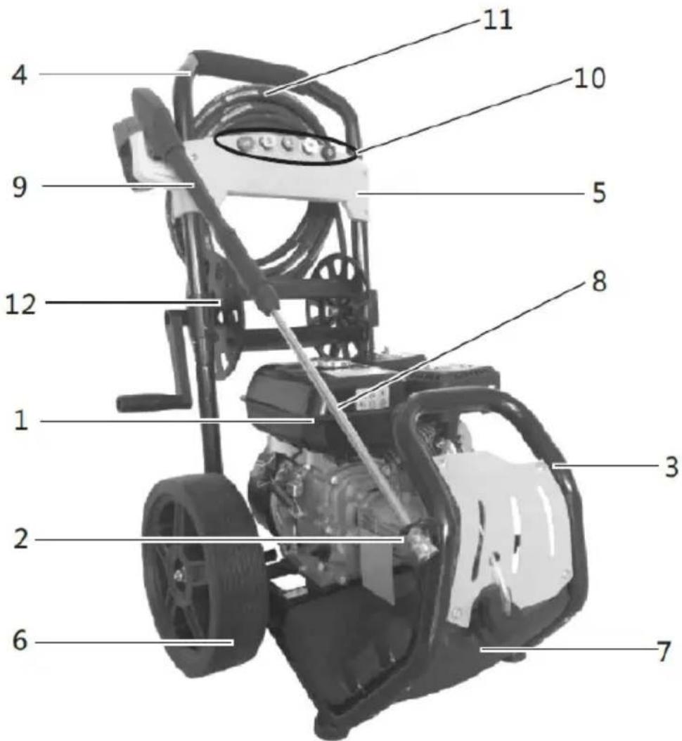
HT-HPW-180A
Hillvert HT-HPW-180 - Product overview - 2

text_image Labeled diagram of a power saw machine with numbered parts for identification
  1. Motor
  2. Pump
  3. Lower frame
  4. Transport handle
  5. Control panel
  6. Circle (x2)
  7. Cleaning agent container
  8. Lance
  9. The gun

  10. Nozzle

  11. Reinforced hose
  12. Hose reel

3.2. Preparation for operation

POSITIONING OF THE UNIT

The ambient temperature must not exceed 45^ C. Use the device only in well-ventilated areas, preferably in open spaces. Do not obstruct the exhaust outlet from the engine. Keep the unit away from any hot surfaces. Always operate the unit on a level, stable, clean, fireproof surface and out of the reach of children and persons with impaired mental, sensory, and intellectual functions. The working place of the device should provide immediate access to the water shut-off valve and engine ignition. It is important to ensure that the pressure of the water supply to the device does not exceed the recommended range.

3.2.1 General description of the engine
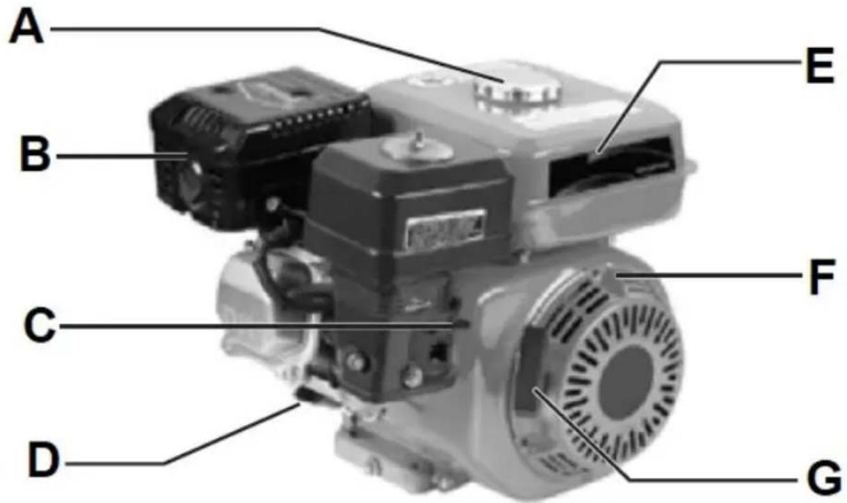
Hillvert HT-HPW-180 - General description of the engine - 1

text_image A B C D E F G

A. Fuel filler cap
B. Muffler with exhaust pipe
C. Manual suction lever
D. Oil filler plug with dipstick
E. Fuel tank
F. Ignition switch (not visible in the picture - on the other side)
G. Starter tugger handle

DEVICE ASSEMBLY AND PREPARATION FOR WORK:

HT-HPW-180

a) Insert the axle into the special hole on the bottom of the subframe and then fix it with M6 screws:
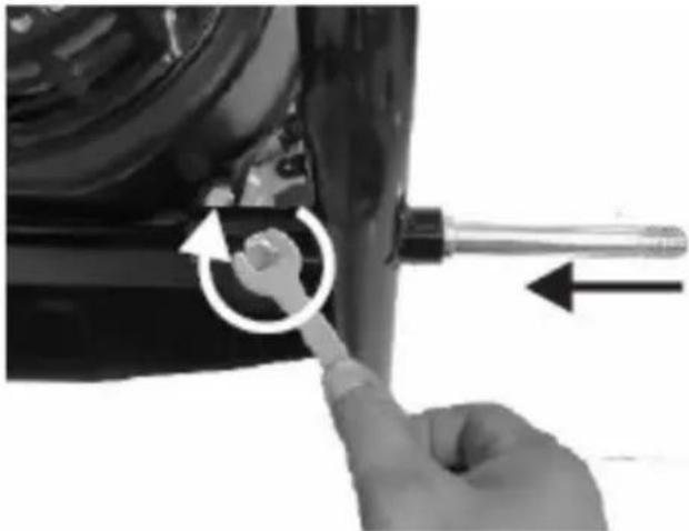
Hillvert HT-HPW-180 - HT-HPW-180 - 1

natural_image Close-up of a hand using a screwdriver to adjust a mechanical component with an arrow indicating rotation (no text or symbols visible)

b) Put the wheels on both sides of the mounted axle and fix them with nuts:
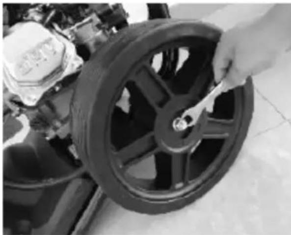
Hillvert HT-HPW-180 - HT-HPW-180 - 2

natural_image Close-up of a hand adjusting a black tire on a motorcycle wheel (no visible text or symbols)

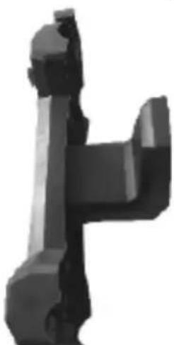
c) Attach the hose hanger:

Hillvert HT-HPW-180 - HT-HPW-180 - 3

natural_image 3D rendered mechanical component resembling a valve or lever (no text or symbols visible)

d) Attach the nozzle panel to the top of the frame:
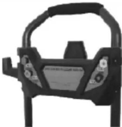
Hillvert HT-HPW-180 - HT-HPW-180 - 4

natural_image Black and white photo of a vehicle steering wheel (no visible text or symbols)

e) Attach the upper part of the frame with the handle to the lower one by overlapping it until the locking latch engages:
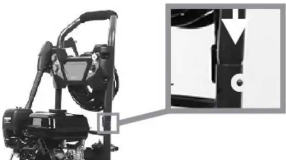
Hillvert HT-HPW-180 - HT-HPW-180 - 5

natural_image Industrial machine with attached cable and mechanical components, shown in black and white (no visible text or symbols)

f) Fill the engine with engine oil according to the recommended specifications, as the device is deprived of it for transportation. The engine has 2 filler caps (signed as "OIL") - front and rear - you only need to use one of them to fill the oil. Set the device on a straight, level surface and pour enough engine oil so that its cold level reaches the upper-acceptable limit marked on the dipstick on one of the filler plugs when it is inserted back into its opening:
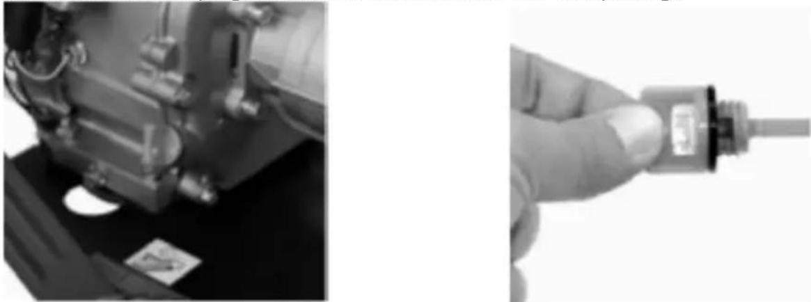
Hillvert HT-HPW-180 - HT-HPW-180 - 6

natural_image Close-up of a mechanical component being handled with a tool, showing no visible text or symbols.

ATTENTION: in the event of overfilling the engine oil above the allowable, safe level on the dipstick, the excess oil can be sucked off.

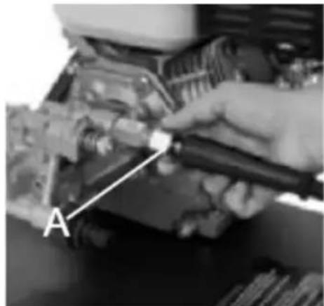
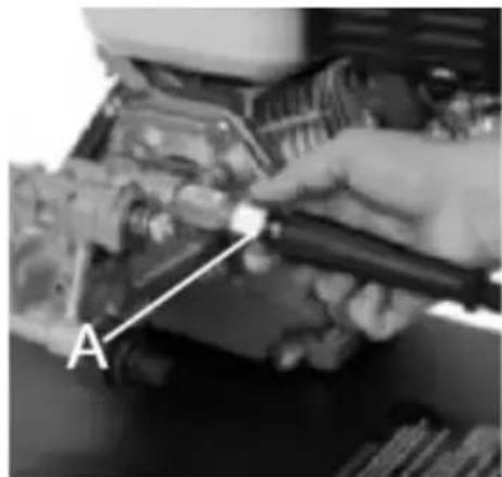
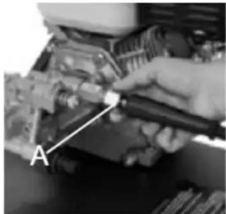
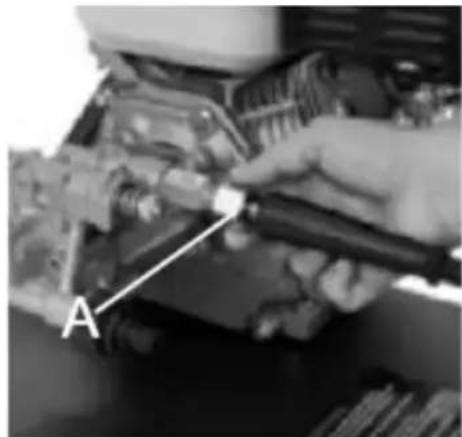
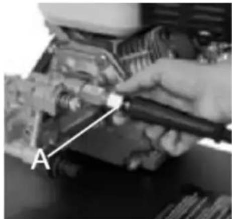
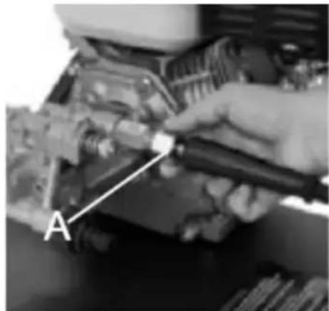
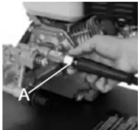
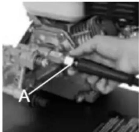
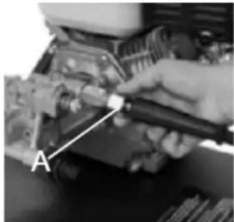
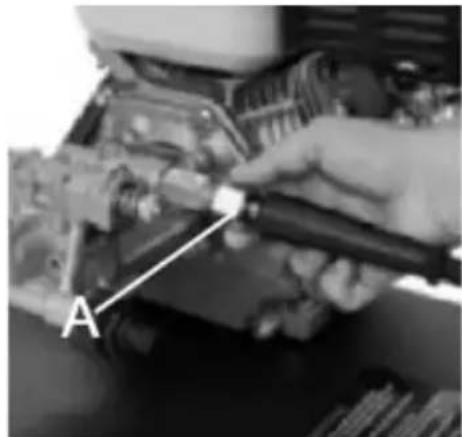
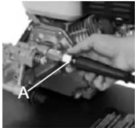
g) Connect the reinforced high-pressure hose to the outlet (A in the figure below) on the pump housing:
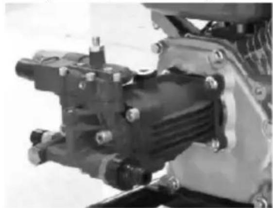
Hillvert HT-HPW-180 - HT-HPW-180 - 7

natural_image Close-up of a mechanical pump assembly with mounting flanges and bolts (no visible text or symbols)

Hillvert HT-HPW-180 - HT-HPW-180 - 8

natural_image Close-up of a hand using a tool to adjust or install an engine component, labeled 'A' with no visible text or symbols beyond the label.

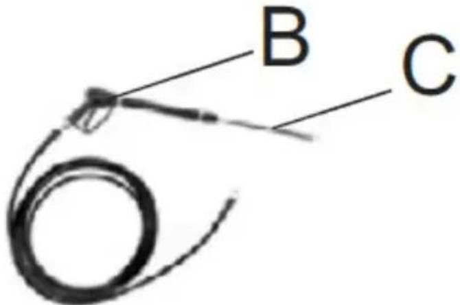
h) Connect the other end of the pressure hose to the gun (B in Fig. below), and insert the spray lance (C in fig.) into the end of the gun - pressing it in with a spring and then turning it until the lug on its end snaps into place:
Hillvert HT-HPW-180 - HT-HPW-180 - 9

text_image B C

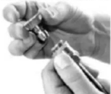
i) Put the required nozzle on the lance by reversing the flange on the end of the nozzle and making sure that it is securely seated after application when the flange returns to the original connection:
Hillvert HT-HPW-180 - HT-HPW-180 - 10

natural_image Close-up of a hand holding a small object, possibly a tool or device, with no visible text or symbols.

IMPORTANT: Inaccurate mounting of the nozzle may cause it to fall off spontaneously during use, which may result in property damage or injury to the operator.

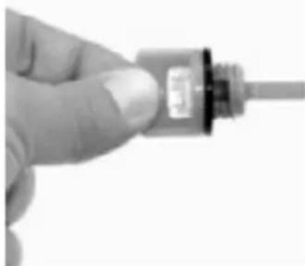
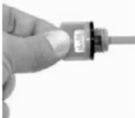
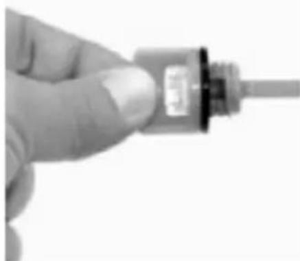
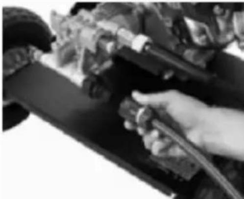
j) Connect the hose with the (twisted) water supply to the connector on the unit's pump:
Hillvert HT-HPW-180 - HT-HPW-180 - 11

natural_image Close-up of a hand adjusting a vehicle's wheel assembly (no visible text or symbols)

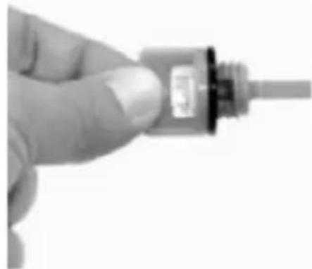
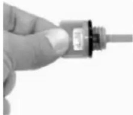
k) Pour fuel into the tank taking care not to overfill beyond the maximum allowable level - above the top line of the screen filter constriction in the filler.

HT-HPW-180

a) Insert the axle into the special hole on the bottom of the subframe and then fix it with M6 screws:
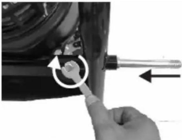
Hillvert HT-HPW-180 - HT-HPW-180 - 1

natural_image Close-up of a hand using a screwdriver to adjust a mechanical component with an arrow indicating rotation (no text or symbols visible)

b) Put the wheels on both sides of the mounted axle and fix them with nuts:
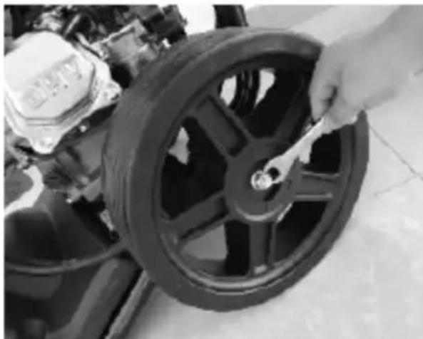
Hillvert HT-HPW-180 - HT-HPW-180 - 2

natural_image Close-up of a hand adjusting a black tire on a motorcycle wheel (no visible text or symbols)

c) Follow the arrow marked in the picture below to attach the hose spool:
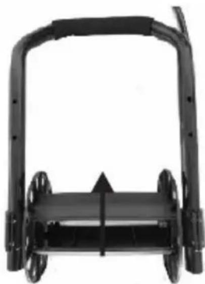
Hillvert HT-HPW-180 - HT-HPW-180 - 3

natural_image Black plastic roller roller with mounting flanges and a handle (no text or symbols visible)

d) Fix the transport bracket with the upper part of the frame on the lower part of the frame until the latch snaps into the corresponding hole (A in the following figure):
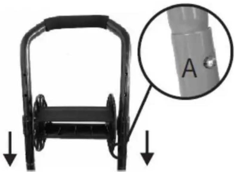
Hillvert HT-HPW-180 - HT-HPW-180 - 4

natural_image Mechanical component with a magnified inset showing a labeled part 'A' (no text or symbols on the main subject)

e) In order to fix the spool on the weight, it should be tightened with a screw:
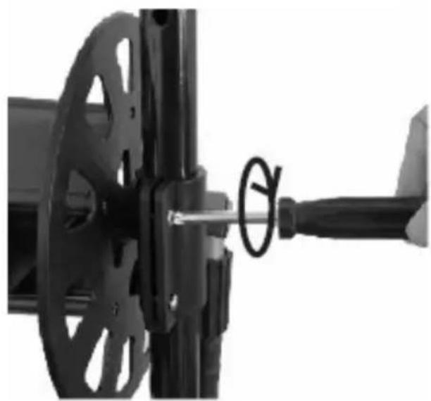
Hillvert HT-HPW-180 - HT-HPW-180 - 5

natural_image Close-up of a mechanical assembly with a rotating wheel and lever (no visible text or symbols)

f) According to the arrow in the image below, insert the lever into the mounting hole of the hose spool:
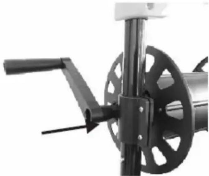
Hillvert HT-HPW-180 - HT-HPW-180 - 6

natural_image Close-up of a mechanical device with a black handle and circular component, no visible text or symbols

g) Mount the nozzle panel on the device as shown in the picture below:
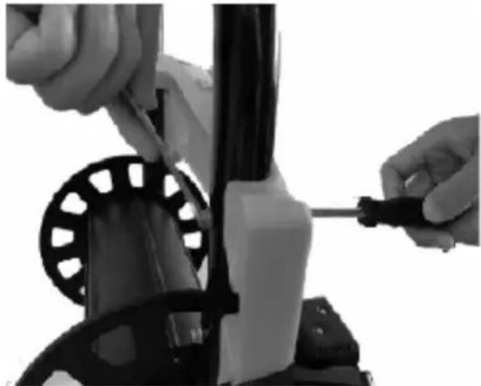
Hillvert HT-HPW-180 - HT-HPW-180 - 7

natural_image Close-up of hands installing or adjusting a mechanical component with a screwdriver (no visible text or symbols)

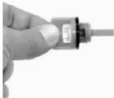
h) Fill the engine with engine oil according to the recommended specifications, as the device is deprived of it for transportation. The engine has 2 filler plugs - front and rear - just unscrew one of them to fill the oil. Set the device on a straight, level surface and pour enough engine oil so that its cold level reaches the upper-acceptable limit marked on the dipstick on one of the filler plugs when it is inserted back into its opening:
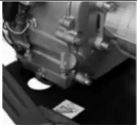
Hillvert HT-HPW-180 - HT-HPW-180 - 8

natural_image Close-up of a mechanical component with no visible text or symbols

Hillvert HT-HPW-180 - HT-HPW-180 - 9

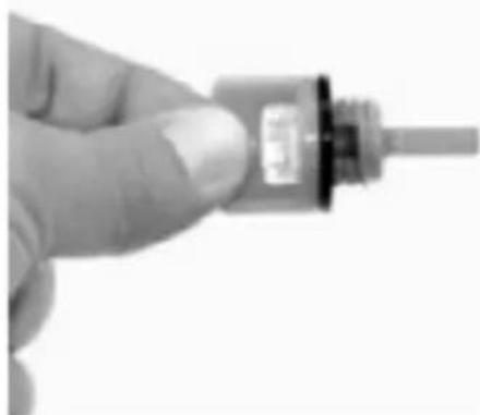
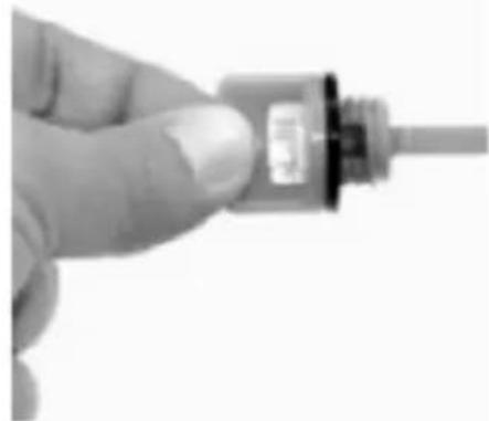
natural_image Close-up of a hand holding a small electronic component with a metallic connector (no visible text or symbols)

ATTENTION: in the event of overfilling the engine oil above the allowable, safe level on the dipstick, the excess oil can be sucked off.

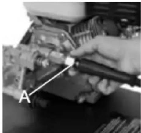
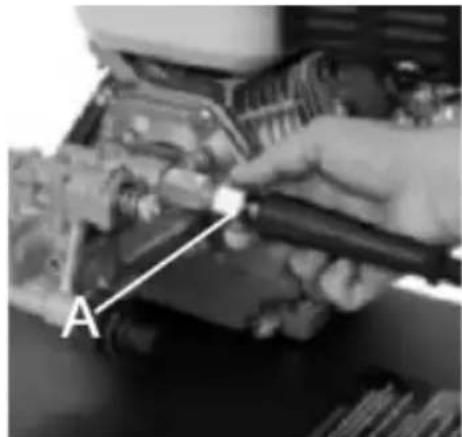
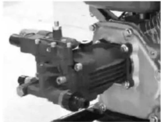
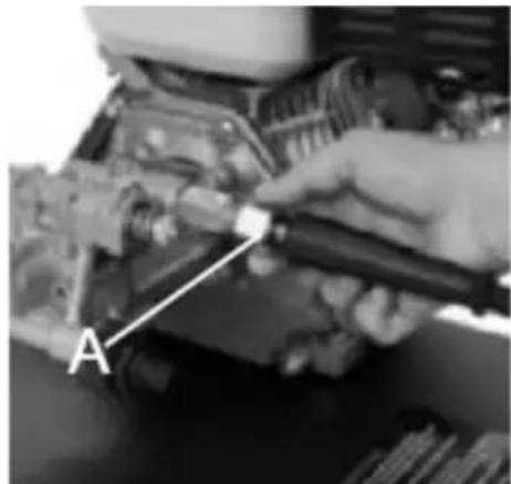
i) Connect the reinforced high-pressure hose to the outlet (A in the figure below) on the pump housing:
Hillvert HT-HPW-180 - HT-HPW-180 - 10

natural_image Close-up of a mechanical assembly with bolts and a central component (no visible text or symbols)

Hillvert HT-HPW-180 - HT-HPW-180 - 11

natural_image Close-up of a hand using a tool to adjust or install an engine component, labeled 'A' with no visible text or symbols beyond the label.

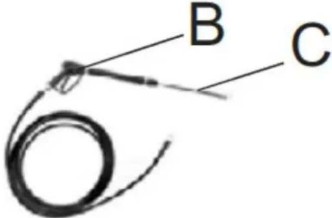
j) Connect the other end of the pressure hose to the gun (B in Fig. below), and insert the spray lance (C in fig.) into the end of the gun - pressing it in with a spring and then turning it until the lug on its end snaps into place:
Hillvert HT-HPW-180 - HT-HPW-180 - 12

text_image B C

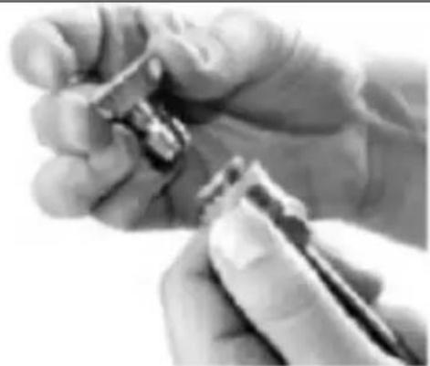
k) Put the required nozzle on the lance by reversing the flange on the end of the nozzle and making sure that it is securely seated after application when the flange returns to the original connection:
Hillvert HT-HPW-180 - HT-HPW-180 - 13

natural_image Close-up of a hand holding a small object, possibly a tool or device, with no visible text or symbols.

IMPORTANT: Inaccurate mounting of the nozzle may cause it to fall off spontaneously during use, which may result in property damage or injury to the operator.

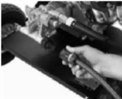
I) Connect the hose with the (twisted) water supply to the connector on the unit's pump:
Hillvert HT-HPW-180 - HT-HPW-180 - 14

natural_image Close-up of a hand adjusting a vehicle's engine compartment with hoses and sensors (no visible text or symbols)

m) Pour fuel into the tank taking care not to overfill beyond the maximum allowable level - above the top line of the screen filter constriction in the filler.

3.3. Working with the device

3.3.1 Turning on/off

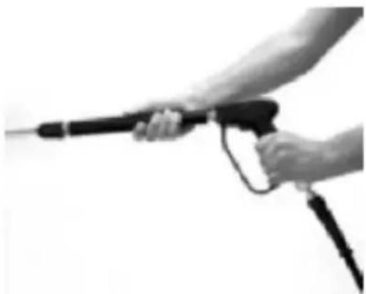
a) Turn on the water supply and squeeze the trigger on the spray gun to get rid of air from the system, that is, until a uniform stream of water begins to pour out of the nozzle:
Hillvert HT-HPW-180 - Turning on/off - 1

natural_image Close-up of a hand holding a handheld electric gun, no visible text or symbols

IMPORTANT: when starting for the first time, it is advisable to press the trigger on the gun while pulling the starter tug to make it easier to start the device.

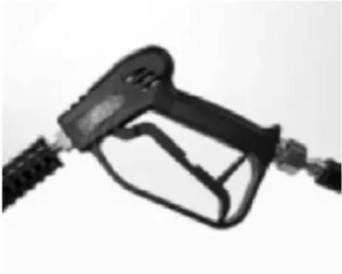
NOTE: the gun trigger has a lock to prevent accidental activation:
Hillvert HT-HPW-180 - Turning on/off - 2

natural_image Close-up of a black fuel pump nozzle with attached tubing (no visible text or symbols)

b) Open the fuel valve (see the distributor icon) by moving its lever in the direction of the pointer (see "A" in the image below):
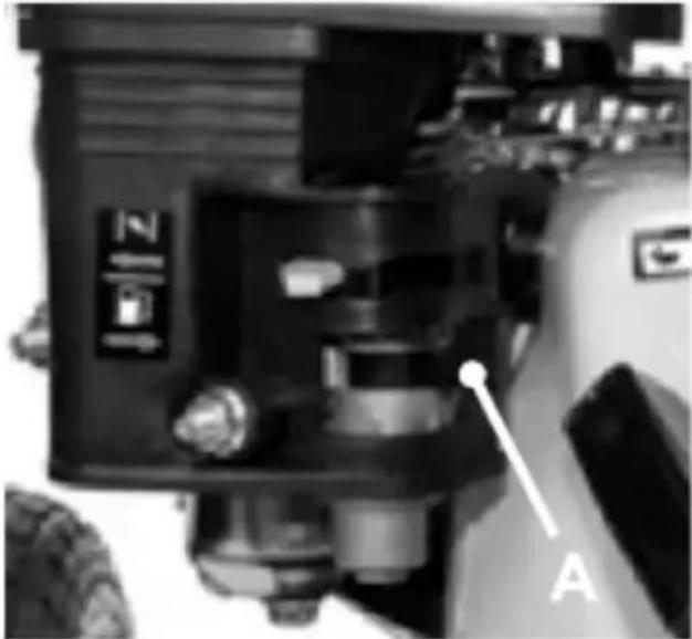
Hillvert HT-HPW-180 - Turning on/off - 3

natural_image Close-up of a mechanical component with labeled parts (A and Z) and no readable text or symbols beyond labels

c) Turn on the suction, that is, move the lever in the closed direction or to the "COLD" position:
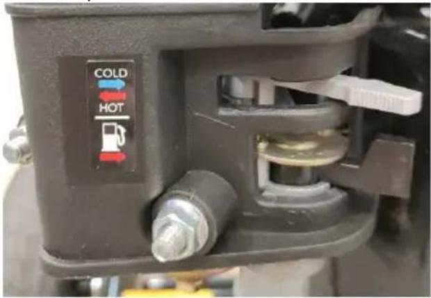
Hillvert HT-HPW-180 - Turning on/off - 4

text_image COLD HOT

NOTE: do not use suction if the engine is warm or the operating environment is hot.

d) Turn on the engine ignition by turning its knob from "OFF" to "ON", i.e. by turning it clockwise:
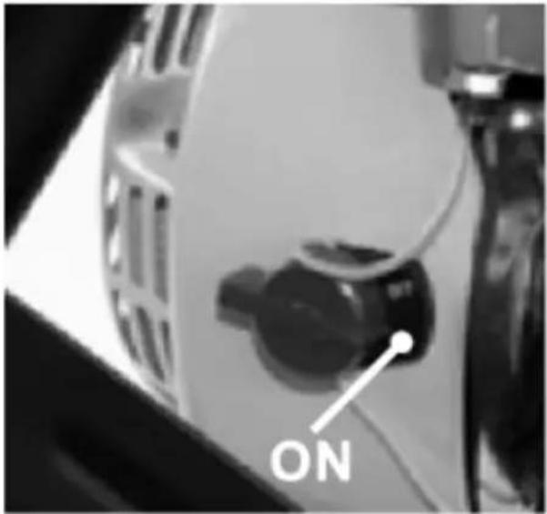
Hillvert HT-HPW-180 - Turning on/off - 5

text_image ON

e) Grab the handle of the starter tug and pull it slowly but steadily until you feel resistance, and then pull with a firm motion but still do not release the handle from your hand or pull to the very end of the tug cable:
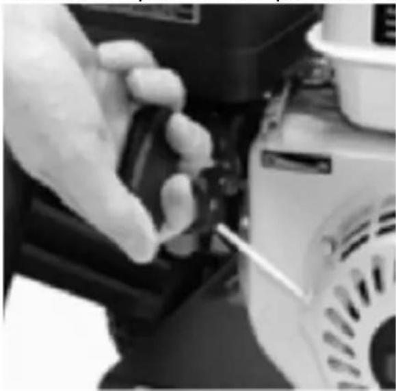
Hillvert HT-HPW-180 - Turning on/off - 6

natural_image Close-up of a gloved hand using a screwdriver to adjust or install a mechanical component (no visible text or symbols)

f) After the engine starts, give it a moment to work on the suction to reach operating temperature before turning off the suction by moving its lever to the "HOT" position.

NOTE: sometimes it may be necessary to pull the starter tug a few times before the engine starts and this is a normal occurrence, especially in cold conditions, just as it may take the engine a little longer to reach operating temperature in cold conditions.

g) Once the engine has warmed up, you can use the throttle lever (D in the image below) to set the desired engine speed - the rabbit icon means high speed, and the turtle icon means low speed, so moving the throttle lever in the appropriate direction increases or decreases the engine speed:
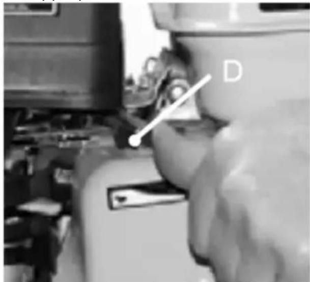
Hillvert HT-HPW-180 - Turning on/off - 7

text_image D

h) You can start washing by pressing the trigger of the gun.

i) To turn off the device first turn the ignition switch to the "OFF" position to stop the engine:
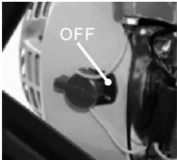
Hillvert HT-HPW-180 - Turning on/off - 8

text_image OFF

j) Close the fuel valve by moving its lever in the opposite direction to the open one.

k) After turning off the device and turning off the water supply, get rid of residual pressurized water from the device by pressing the trigger of the gun until water stops flowing out of the spray lance.

3.3.2 Selecting the correct tip/nozzle

Depending on the model, there are different nozzles to choose from that differ in the water jet and pressure generated:

  • 0 ° (red) - generates a very precise, point stream with the highest pressure. This nozzle is for use only on very durable surfaces like metal or concrete. Do not use on wood etc. delicate surfaces!
  • 15 ° (yellow) / 25 ° (green) - generating a strong flow of 15 ° / 25 ° deviation in both directions from the center of the nozzle. Use these nozzles only on surfaces that can withstand high pressure.
  • 40 ° (white) - a nozzle generating a medium-strong stream with ^a deviation of 40, suitable for use on most surfaces and for universal use, e.g. washing a vehicle.
  • Soap / 84 ° (black) - a special nozzle with low pressure and a very wide stream, dedicated to the application of various cleaning agents, e.g. active foam. This nozzle should be used with special agents, which are poured into a separate cleaning agent tank (see separate description).

3.3.3 Washing with a cleaning agent

ATTENTION: use only cleaning agents specifically designed for pressure washers, taking into account that some agents may work differently and have different densities at lower as at higher temperatures. For details, look at the application instructions on the packaging of the agent in question.

  • Attach the black nozzle to the end of the spray lance.
  • Pour the cleaning agent into the special tank (signed "SOAP" on the cap), taking care that the hose sucking the agent after reattaching the tank lid reaches the bottom of the tank:

HT-HPW-180
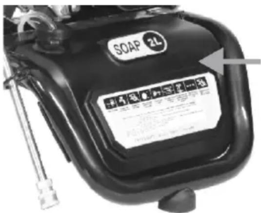
Hillvert HT-HPW-180 - Washing with a cleaning agent - 1

natural_image Close-up of a mechanical component with a circular opening and a white arrow pointing to it (no visible text or symbols)

• The agent will be sprayed along with water.

- Do not leave any unused agent in the tank, but empty it before putting the unit into storage.

3.3.4 Unblocking the nozzle

Sometimes it may happen that the water jet from the nozzle is uneven or unstable, i.e. it interrupts. If the flow does not improve after a while, the nozzle is most likely clogged. In this case, please:

  • Release the trigger of the gun.
  • Turn off the device
  • Trigger the gun to release any residual water and pressure from the gun.
  • Remove the nozzle from the spray lance and inspect it for a blocked opening.
  • Use the supplied needle with a finger eyelet to thread the blocked nozzle.
  • Reattach the nozzle to the spray lance and see if cleaning helped.

3.4. Cleaning and maintenance

a) Before any cleaning, adjustment, or replacement of accessories, and if the device is not in use, pull out and completely cool down the device, wait for the rotating parts to stop, and get rid of residual water with pressure from the system.
b) Use only non-corrosive cleaning agents for cleaning the surfaces.
c) Store the unit in a dry and cool place protected from moisture and direct sunlight.
d) Do not spray the unit with a stream of water or immerse it in water.
e) Make sure that no water enters through the ventilation openings in the casing.
f) Clean the ventilation openings with a brush and compressed air.

g) Perform regular inspections of the unit checking technical fitness and any damages.

h) Use a soft, damp cloth for cleaning.

i) Do not use sharp and/or metal objects (e.g. wire brush or metal spatula) for cleaning as they may damage the surface of the appliance material.

j) After every 150 operating hours and the unit has cooled down, empty the fuel tank, remove the mesh filter from the filler neck, and clean it (e.g. when rinsing in gasoline):
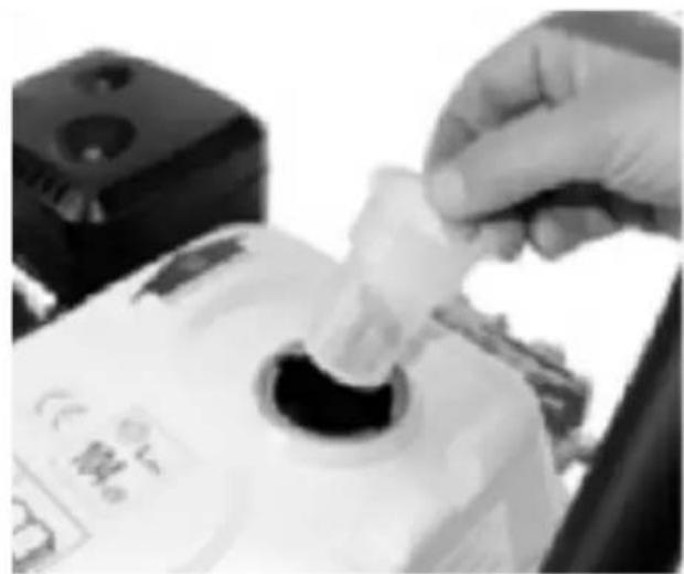
Hillvert HT-HPW-180 - Cleaning and maintenance - 1

natural_image Close-up of a hand inserting a small object into a cylindrical container, with no visible text or symbols.

Rinse the fuel tank as well.

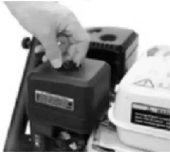
k) Every 100 operating hours or six months (whichever comes first), remove and clean or replace the engine air filter if necessary:
Hillvert HT-HPW-180 - Cleaning and maintenance - 2

natural_image Close-up of a hand pressing a button on an electronic device (no visible text or symbols)

Rinse the filter fit for further use in warm water with mild detergent and dry completely before reassembly.

ATTENTION: never start the engine without the air filter! Service the air filter more frequently if the device operates in extremely dusty conditions.

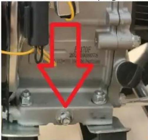
I) The engine oil should be changed after the first 20 operating hours after startup, and every 100 or six months thereafter (depending on what is lost sooner):

- Run the engine for a few minutes to warm up the oil - warm oil is thinner and drains faster.

ATTENTION: oil in an engine that has recently been running may be hot - risk of burns!

- Place the device on an even and stable surface.

- Place a waste oil container under the oil drain plug.

• Unscrew one of the oil filler plugs.

• Unscrew the oil drain plug carefully.
Hillvert HT-HPW-180 - Cleaning and maintenance - 3

text_image E170F 2024 104380725

- Wait until the used oil finishes draining while assessing the condition of the plug gasket - if it is damaged or worn, then replace it with a new one.

- Screw the oil drain plug back on.

• Fill up with fresh oil through the filler cap.

m) If the device is not used for more than one month:

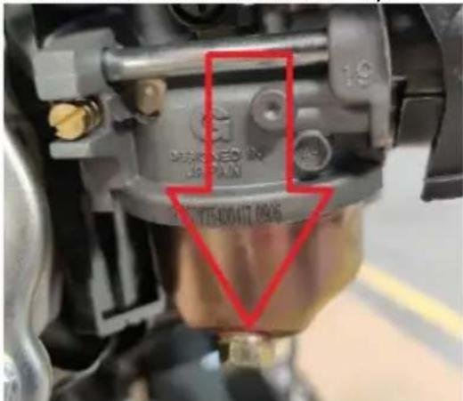
- empty the fuel from the tank and fuel system by unscrewing the precipitation filter (photo below) or removing the fuel hose from the carburetor, or adding a stabilizer to the fuel (follow the additive manufacturer's instructions).
Hillvert HT-HPW-180 - Cleaning and maintenance - 4

text_image DECKLED JP-PAI 197075400417 0846

ATTENTION: never keep fuel in the unit longer than allowed by the manufacturer of the added stabilizing additive!

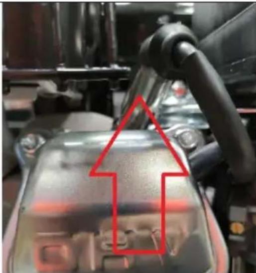
- Remove the ignition wire pipe from the spark plug and unscrew the spark plug:
Hillvert HT-HPW-180 - Cleaning and maintenance - 5

natural_image Close-up of a mechanical component with a red arrow pointing to a highlighted area, no visible text or symbols.

- Pour 1 tablespoon of fresh engine oil into the cylinder through the spark plug hole and (with the ignition off) gently pull the starter tug lever several times until resistance (compression) is felt to distribute the oil in the cylinder.

• Reinstall the spark plug in the engine.

- Replace the engine oil with fresh oil.

n) Every 100 working hours or six months (whichever comes first), remove the spark plug and check the condition of its electrodes, and if necessary clean the electrodes with a wire brush. Before reassembling the spark plug, it is necessary to check the spark plug washer and the gap between them and, if necessary, set the correct one. If the candle turns out to be worn out, replace it with a new one, or a suitable replacement.

o) Change the gear oil in the pump mechanism every 100 operating hours. Every once in a while you change the gear oil, you can flush the system by pouring out the used oil and pouring purified kerosene into the system first and running the unit for 10-15 seconds before pouring in fresh oil. Then drain the kerosene and then pour in the fresh gear oil.

DISPOSAL OF WASTE APPLIANCES

At the end of its useful life, this product should not be disposed of with normal household waste but should be taken to a collection point for the recycling of electrical and electronic equipment. This is indicated by the symbol on the product, operating instructions, or packaging. The materials used in this appliance are recyclable according to their marking. By reusing, recycling, or applying other forms of use of waste machines, you make a significant contribution to the protection of our environment.

Your local administration will provide you with information about the appropriate disposal point for used appliances.

Hillvert HT-HPW-180 - DISPOSAL OF WASTE APPLIANCES - 1

text_image Labeled diagram of a mechanical device with numbered parts for identification
text_image A B C D E F G
natural_image Close-up of a hand using a screwdriver to adjust a mechanical component with an arrow indicating rotation (no text or symbols visible)
natural_image Close-up of a hand adjusting a black tire on a motorcycle wheel (no visible text or symbols)
natural_image 3D rendered mechanical component resembling a valve or connector (no text or symbols visible)
natural_image Black and white photo of a futuristic vehicle steering wheel (no visible text or symbols)
natural_image Industrial machine with attached hoses and a close-up inset showing internal components (no visible text or symbols)
natural_image Close-up of a mechanical device with no visible text or symbols

Hillvert HT-HPW-180 - DISPOSAL OF WASTE APPLIANCES - 2

natural_image Close-up of a hand holding a small electronic component with a metallic shaft (no visible text or symbols)
natural_image Close-up of a mechanical assembly with bolts and a central component (no visible text or symbols)

Hillvert HT-HPW-180 - DISPOSAL OF WASTE APPLIANCES - 3

natural_image Close-up of a hand using a tool to adjust or install a mechanical component, labeled 'A' with an arrow pointing to the tool (no readable text or symbols beyond label)
natural_image Close-up of a hand holding a small object, possibly a tool or device, with no visible text or symbols.
natural_image Close-up of a hand adjusting a vehicle's wheel and dashboard components (no visible text or symbols)
natural_image Close-up of a hand using a screwdriver to adjust a mechanical component with an arrow indicating rotation (no text or symbols visible)
natural_image Close-up of a hand adjusting a black tire on a motorcycle wheel (no visible text or symbols)
natural_image Black plastic roller or pulley device with mounting flanges and a handle (no text or symbols visible)
natural_image Mechanical component with a magnified inset showing a labeled part 'A' (no text or symbols on the main subject)
natural_image Close-up of a mechanical device with a rotating wheel and lever mechanism (no visible text or symbols)
natural_image Close-up of a mechanical device with a black handle and circular component, no visible text or symbols
natural_image Close-up of hands assembling a bicycle wheel assembly with a screwdriver (no visible text or symbols)
natural_image Close-up of a mechanical component being handled with a tool, no visible text or symbols
natural_image Mechanical assembly diagram showing a valve mechanism and a hand holding a tool, with no visible text or symbols.
natural_image Close-up of hands holding a small object, possibly a tool or device, with no visible text or symbols.
natural_image Close-up of a hand adjusting automotive components on a vehicle chassis (no visible text or symbols)
natural_image Black-and-white photo of a hand holding a handheld electric gun (no text or symbols visible)
natural_image Close-up of a black fuel pump nozzle with attached cable (no visible text or symbols)
natural_image Close-up of a mechanical component with labeled parts (A and Z14) and no readable text or symbols beyond labels
natural_image Close-up of a gloved hand using a tool to adjust or install electronic components (no visible text or symbols)
natural_image Close-up of a mechanical component with a circular opening and a white arrow pointing to it (no visible text or symbols)
natural_image Close-up of a hand holding a small white object with a dark circular opening, next to a device (no visible text or symbols)
natural_image Close-up of a hand pressing a button on an electronic device (no visible text or symbols)
natural_image Close-up of a car engine bay with a red arrow pointing to the interior (no visible text or symbols)
text_image Labeled diagram of a power saw machine with numbered parts for identification
text_image A B C D E F G
natural_image Close-up of a hand using a screwdriver to adjust a mechanical component with an arrow indicating rotation (no text or symbols visible)
natural_image Close-up of a hand adjusting a black tire on a motorcycle wheel (no visible text or symbols)
natural_image 3D rendered mechanical component resembling a valve or connector (no text or symbols visible)
natural_image Black and white photo of a futuristic vehicle steering wheel (no visible text or symbols)
natural_image Industrial machine with attached hoses and a close-up inset showing internal components (no visible text or symbols)
natural_image Close-up of a mechanical device with no visible text or symbols

Hillvert HT-HPW-180 - DISPOSAL OF WASTE APPLIANCES - 4

natural_image Close-up of a hand holding a small electronic component with a metallic connector (no visible text or symbols)
natural_image Close-up of a mechanical assembly with bolts and a central component (no visible text or symbols)

Hillvert HT-HPW-180 - DISPOSAL OF WASTE APPLIANCES - 5

natural_image Close-up of a hand using a tool to adjust or install a mechanical component, labeled 'A' with an arrow pointing to the tool (no readable text or symbols beyond label)
natural_image Close-up of a hand holding a small object, possibly a tool or device, with no visible text or symbols.
natural_image Close-up of a hand adjusting automotive components on a vehicle (no visible text or symbols)
natural_image Close-up of a hand using a wrench to adjust a mechanical component, with an arrow indicating rotation (no text or symbols visible)
natural_image Close-up of a hand adjusting a black tire on a motorcycle wheel (no visible text or symbols)
natural_image Black plastic roller roller with mounting flanges and a handle (no text or symbols visible)
natural_image Mechanical component with a magnified inset showing a labeled part 'A' (no text or symbols on the main subject)
natural_image Close-up of a mechanical device with a circular component and a tool inserted, no visible text or symbols
natural_image Close-up of a mechanical device with a black lever and circular component (no visible text or symbols)
natural_image Close-up of hands assembling a bicycle wheel assembly with a screwdriver (no visible text or symbols)
natural_image Close-up of a mechanical component being processed with a hand holding a screwdriver (no visible text or symbols)
natural_image Close-up of a mechanical assembly with bolts and a central component (no visible text or symbols)

Hillvert HT-HPW-180 - DISPOSAL OF WASTE APPLIANCES - 6

natural_image Close-up of a hand using a tool to adjust or install a mechanical component, labeled 'A' with an arrow pointing to the tool (no readable text or symbols beyond label)
natural_image Close-up of a hand holding a small object, possibly a tool or device, with no visible text or symbols.
natural_image Close-up of a hand adjusting automotive components on a vehicle chassis (no visible text or symbols)
natural_image Close-up of a hand holding a handheld electric gun, no visible text or symbols
natural_image Close-up of a black fuel pump nozzle with attached cable (no visible text or symbols)
natural_image Close-up of a mechanical component with labeled parts (A and Z) and no readable text or symbols beyond labels
natural_image Close-up of a gloved hand using a tool to adjust or install a mechanical component (no visible text or symbols)
natural_image Close-up of a mechanical component with a circular opening and a white arrow pointing to it (no visible text or symbols)
natural_image Close-up of a hand inserting a small object into a container, with a device and camera in the background (no visible text or symbols)
natural_image Close-up of a hand pressing a button on a black industrial control box (no visible text or symbols)
text_image Close-up mechanical component with red annotation highlighting a specific part, showing text and symbols
natural_image Close-up of a metallic vehicle's engine compartment with red arrows highlighting the component (no visible text or symbols)
text_image Labeled diagram of a power saw with numbered parts for identification
text_image A B C D E F G
natural_image Close-up of a hand using a screwdriver to adjust a mechanical component with an arrow indicating rotation (no text or symbols visible)
natural_image Close-up of a hand adjusting a black tire on a motorcycle wheel (no visible text or symbols)
natural_image 3D rendered mechanical part with no visible text or symbols
natural_image Black and white photo of a futuristic vehicle steering wheel (no visible text or symbols)
natural_image Industrial machine with attached hoses and a close-up inset showing internal components (no visible text or symbols)
natural_image Close-up of a hand operating a precision drill bit with a tool, no visible text or symbols
natural_image Close-up of a mechanical assembly with bolts and components (no visible text or symbols)

Hillvert HT-HPW-180 - DISPOSAL OF WASTE APPLIANCES - 7

natural_image Close-up of a hand using a tool to adjust or install a mechanical component, labeled 'A' with no visible text or symbols beyond the label.
natural_image Close-up of hands holding a small mechanical component, possibly a tool or device (no visible text or symbols)
natural_image Close-up of a hand adjusting a vehicle's engine compartment with hoses and sensors (no visible text or symbols)
natural_image Close-up of a hand using a wrench to adjust a mechanical component, with no visible text or symbols.
natural_image Close-up of a hand adjusting a black tire on a motorcycle wheel (no visible text or symbols)
natural_image Black plastic roller roller with mounting flanges and a handle (no text or symbols visible)
natural_image Mechanical component with a close-up view of a labeled part 'A' (no text or symbols on the component itself)
natural_image Close-up of a mechanical assembly with a rotating wheel and lever (no visible text or symbols)
natural_image Close-up of a mechanical device with a black lever and circular component (no visible text or symbols)
natural_image Close-up of hands installing or adjusting a mechanical component with a screwdriver (no visible text or symbols)
natural_image Mechanical assembly diagram showing a valve mechanism and a tool inserted into a component (no text or symbols visible)
natural_image Close-up of a hand holding a small object, possibly a tool or device, with no visible text or symbols.
natural_image Close-up of a hand adjusting automotive components on a vehicle chassis (no visible text or symbols)
natural_image Close-up of a hand holding a handheld electric gun, no visible text or symbols
natural_image Close-up of a black fuel pump nozzle with attached cable (no visible text or symbols)
natural_image Close-up of a mechanical component with labeled parts (A and Z14) and no readable text or symbols beyond labels
natural_image Close-up of a gloved hand using a tool to adjust or install electronic components (no visible text or symbols)
natural_image Close-up of a mechanical component with a black hole and arrow pointing to a circular opening (no text or symbols visible)
natural_image Close-up of a hand inserting a plastic into a white plastic bag with a dark central object (no visible text or symbols)
natural_image Close-up of a hand pressing a button on an electronic device (no visible text or symbols)
text_image EHTOF 2021/03/078
text_image Close-up mechanical component with red annotation highlighting a specific part, showing text and symbols
natural_image Close-up of a mechanical component with a red arrow pointing to a highlighted area, no visible text or symbols.
text_image Labeled diagram of a power saw with numbered parts for identification
text_image A B C D E F G
natural_image Close-up of a hand using a screwdriver to adjust a mechanical component with an arrow indicating rotation (no text or symbols visible)
natural_image Close-up of a hand adjusting a black tire on a motorcycle wheel (no visible text or symbols)
natural_image 3D rendered mechanical component resembling a valve or bracket (no text or symbols visible)
natural_image Black and white photo of a futuristic vehicle steering wheel (no visible text or symbols)
natural_image Industrial machine with attached hoses and a close-up inset showing internal components (no visible text or symbols)
natural_image Close-up of a mechanical device with no visible text or symbols

Hillvert HT-HPW-180 - DISPOSAL OF WASTE APPLIANCES - 8

natural_image Close-up of a hand holding a small mechanical component (no visible text or symbols)
natural_image Close-up of a mechanical pump assembly with mounting flanges and bolts (no visible text or symbols)

Hillvert HT-HPW-180 - DISPOSAL OF WASTE APPLIANCES - 9

natural_image Close-up of a hand using a tool to adjust or install a mechanical component, labeled 'A' with no visible text or symbols beyond the label.
natural_image Close-up of hands holding a small mechanical component, possibly a tool or device (no visible text or symbols)
natural_image Close-up of a hand adjusting a vehicle's engine compartment with hoses and sensors (no visible text or symbols)
natural_image Close-up of a hand using a wrench to adjust a mechanical component with an arrow indicating rotation (no text or symbols visible)
natural_image Close-up of a hand adjusting a black tire on a motorcycle wheel (no visible text or symbols)
natural_image Black plastic roller roller with mounting flanges and a handle (no text or symbols visible)
natural_image Mechanical component with a magnified inset showing a labeled part 'A' (no text or symbols on the main subject)
natural_image Close-up of a mechanical assembly with a rotating wheel and lever (no visible text or symbols)
natural_image Close-up of a mechanical device with a black lever and circular component (no visible text or symbols)
natural_image Close-up of hands installing or adjusting a mechanical component with a black gear and screwdriver (no visible text or symbols)
natural_image Close-up of a mechanical component with no visible text or symbols

Hillvert HT-HPW-180 - DISPOSAL OF WASTE APPLIANCES - 10

natural_image Close-up of a hand holding a small electronic component with a metallic tip (no visible text or symbols)
natural_image Close-up of a mechanical assembly with bolts and a central component (no visible text or symbols)

Hillvert HT-HPW-180 - DISPOSAL OF WASTE APPLIANCES - 11

natural_image Close-up of a hand using a tool to adjust or install electronic components, labeled 'A' with no visible text or symbols beyond the label.
natural_image Close-up of a hand holding a small object, possibly a tool or device, with no visible text or symbols.
natural_image Close-up of a hand adjusting automotive components on a vehicle chassis (no visible text or symbols)
natural_image Close-up of a hand holding a handheld electric gun, no visible text or symbols
natural_image Close-up of a black fuel pump nozzle with attached cable (no visible text or symbols)
natural_image Close-up of a mechanical component with labeled parts (A and Z14) and no readable text or symbols beyond labels
natural_image Close-up of a gloved hand operating a mechanical device with a tool (no visible text or symbols)
natural_image Close-up of a mechanical component with a white tool labeled 'D' pointing to a curved part (no readable text or symbols beyond the label)
natural_image Close-up of a hand holding a small object into a cylindrical container, with a device and mechanical components in the background (no visible text or symbols)
natural_image Close-up of a hand pressing a button on an electronic device (no visible text or symbols)
text_image 19070F 2015-10-03/17
text_image Close-up mechanical component with red annotation highlighting a specific part, showing text and symbols
natural_image Close-up of a mechanical component with a red arrow pointing to a highlighted area, no visible text or symbols.
text_image Labeled diagram of a power saw with numbered parts for identification
text_image A B C D E F G
natural_image Close-up of a hand using a screwdriver to adjust a mechanical component with an arrow indicating rotation (no text or symbols visible)
natural_image Close-up of a hand adjusting a black tire on a motorcycle wheel (no visible text or symbols)
natural_image 3D rendered mechanical component resembling a valve or connector (no text or symbols visible)
natural_image Black and white photo of a futuristic vehicle steering wheel (no visible text or symbols)
natural_image Industrial machine with attached hoses and a close-up inset showing internal components (no visible text or symbols)
natural_image Close-up of a mechanical device with no visible text or symbols

Hillvert HT-HPW-180 - DISPOSAL OF WASTE APPLIANCES - 12

natural_image Close-up of a hand holding a small electronic component with a metallic connector (no visible text or symbols)
natural_image Close-up of a mechanical pump assembly with mounting flanges and housing (no visible text or symbols)

Hillvert HT-HPW-180 - DISPOSAL OF WASTE APPLIANCES - 13

natural_image Close-up of a hand using a flashlight to adjust internal components, labeled 'A' (no text or symbols on the diagram itself)
natural_image Close-up of hands holding a small mechanical component (no visible text or symbols)
natural_image Close-up of a hand adjusting a vehicle's wheel assembly (no visible text or symbols)
natural_image Close-up of a hand using a wrench to adjust a mechanical component, with no visible text or symbols.
natural_image Close-up of a hand adjusting a black bicycle wheel rim, no visible text or symbols
natural_image Black plastic roller or pulley device with mounting flanges and a central arrow indicator (no text or symbols)
natural_image Mechanical component with a close-up view of a cylindrical component labeled 'A', showing structural details and directional arrows (no text or symbols beyond label)
natural_image Close-up of a mechanical device with a rotating wheel and lever mechanism (no visible text or symbols)
natural_image Close-up of a mechanical device with a black lever and circular component (no visible text or symbols)
natural_image Close-up of hands installing or adjusting a mechanical component with a screwdriver (no visible text or symbols)
natural_image Close-up of a mechanical component being handled with a tool, showing no visible text or symbols.
natural_image Mechanical assembly diagram showing two views of a mechanical component with no visible text or symbols
natural_image Close-up of hands holding a small object, possibly a tool or device, with no visible text or symbols.
natural_image Close-up of a hand adjusting automotive components on a vehicle chassis (no visible text or symbols)
natural_image Black-and-white photo of a hand holding a handheld electric gun (no text or symbols visible)
natural_image Close-up of a black fuel pump nozzle with attached cable (no visible text or symbols)
natural_image Close-up of a mechanical component with labeled parts (A and Z14) and no readable text or symbols beyond labels
natural_image Close-up of a gloved hand using a tool to adjust or install a mechanical component (no visible text or symbols)
natural_image Close-up of a mechanical component with a circular opening and a white arrow pointing to it (no visible text or symbols)
natural_image Close-up of a hand holding a small object with a white plastic tip, next to a device (no visible text or symbols)
natural_image Close-up of a hand pressing a button on a black industrial control box (no visible text or symbols)
natural_image Close-up of a mechanical component with a red arrow pointing to a highlighted area, no visible text or symbols.
text_image Labeled diagram of a power saw with numbered parts for identification
text_image A B C D E F G
natural_image Close-up of a hand using a wrench to adjust a mechanical component with an arrow indicating rotation (no text or symbols visible)
natural_image Close-up of a hand adjusting a black tire on a motorcycle wheel (no visible text or symbols)
natural_image 3D rendered mechanical component resembling a valve or connector (no text or symbols visible)
natural_image Black and white photo of a futuristic vehicle steering wheel (no visible text or symbols)
natural_image Industrial machine with attached hoses and a close-up inset showing internal components (no visible text or symbols)
natural_image Close-up of a mechanical device with no visible text or symbols

Hillvert HT-HPW-180 - DISPOSAL OF WASTE APPLIANCES - 14

natural_image Close-up of a hand holding a small electronic component with a metallic connector (no visible text or symbols)
natural_image Close-up of a mechanical assembly with bolts and components (no visible text or symbols)

Hillvert HT-HPW-180 - DISPOSAL OF WASTE APPLIANCES - 15

natural_image Close-up of a hand using a tool to adjust or install a mechanical component, labeled 'A' with no visible text or symbols beyond the label.
natural_image Close-up of hands holding a small object, possibly a tool or device, with no visible text or symbols.
natural_image Close-up of a hand adjusting a mechanical component with hoses and gears (no visible text or symbols)
natural_image Close-up of a hand using a wrench to adjust a mechanical component, with no visible text or symbols.
natural_image Close-up of a hand adjusting a black tire on a motorcycle wheel (no visible text or symbols)
natural_image Black plastic roller or pulley device with no visible text or symbols
natural_image Mechanical component with a magnified inset showing a labeled part 'A' (no text or symbols on the main subject)
natural_image Close-up of a mechanical device with a circular tool inserted into a shaft (no visible text or symbols)
natural_image Close-up of a mechanical device with a black lever and circular component (no visible text or symbols)
natural_image Close-up of hands installing or adjusting a mechanical component with a screwdriver (no visible text or symbols)
natural_image Close-up of a mechanical component with no visible text or symbols

Hillvert HT-HPW-180 - DISPOSAL OF WASTE APPLIANCES - 16

natural_image Close-up of a hand holding a small electronic component with a metallic connector (no visible text or symbols)
natural_image Close-up of a mechanical assembly with bolts and a central component (no visible text or symbols)

Hillvert HT-HPW-180 - DISPOSAL OF WASTE APPLIANCES - 17

natural_image Close-up of a hand using a tool to adjust or install an engine component, labeled 'A' with no visible text or symbols beyond the label.
natural_image Close-up of a hand holding a small metallic object, possibly a tool or component (no visible text or symbols)
natural_image Close-up of a hand adjusting automotive components on a vehicle chassis (no visible text or symbols)
natural_image Close-up of a hand holding a handheld electric gun, no visible text or symbols
natural_image Close-up of a black fuel pump nozzle with attached tubing (no visible text or symbols)
natural_image Close-up of a mechanical component with labeled parts (A and Z) and no readable text or symbols beyond labels
natural_image Close-up of a gloved hand operating a mechanical device with a tool inserted (no visible text or symbols)
natural_image Close-up of a mechanical component with a circular opening and a white arrow pointing to it (no visible text or symbols)
natural_image Close-up of a hand holding a small object into a cylindrical container, with a device and mechanical components in the background (no visible text or symbols)
natural_image Close-up of a hand pressing a button on a black industrial control box, with a white plastic container nearby (no visible text or symbols)
natural_image Close-up of a mechanical component with a red arrow pointing to a highlighted area, no visible text or symbols.
text_image Labeled diagram of a power saw machine with numbered parts for identification
  1. Motor
  2. Pumpe
  3. Nedre ramme
  4. Transporthåndtag
  5. Kontrolpanel
  6. Cirkel (x2)
  7. Beholder til rengøringsmiddel
  8. Lance
  9. Pistolen
  10. Dyse

  11. Rustet slange

  12. Slangerulle

APPARATETS PLACERING

text_image A B C D E F G
natural_image Close-up of a hand using a screwdriver to adjust a mechanical component with an arrow indicating rotation (no text or symbols visible)
natural_image Close-up of a hand adjusting a black tire on a motorcycle wheel (no visible text or symbols)
natural_image 3D rendered mechanical component resembling a valve or connector (no text or symbols visible)
natural_image Black and white photo of a vehicle steering wheel (no visible text or symbols)
natural_image Industrial machine with attached hose and control panel, shown in black-and-white (no visible text or symbols)
natural_image Close-up of a mechanical device with no visible text or symbols

Hillvert HT-HPW-180 - APPARATETS PLACERING - 1

natural_image Close-up of a hand holding a small electronic component with a metallic connector (no visible text or symbols)
natural_image Close-up of hands holding a small object, possibly a tool or device, with no visible text or symbols.
natural_image Close-up of a hand adjusting a mechanical component with hoses and gears (no visible text or symbols)
natural_image Close-up of a hand using a wrench to adjust a mechanical component, with no visible text or symbols.
natural_image Close-up of a hand adjusting a black tire on a motorcycle wheel (no visible text or symbols)
natural_image Black plastic roller roller with mounting flanges and a handle (no text or symbols visible)
natural_image Mechanical component with a magnified inset showing a labeled part 'A' (no text or symbols on the main subject)
natural_image Close-up of a mechanical assembly with a rotating wheel and lever (no visible text or symbols)
natural_image Close-up of a mechanical device with a black handle and circular component, no visible text or symbols
natural_image Close-up of hands installing or adjusting a mechanical component with a screwdriver (no visible text or symbols)
natural_image Close-up of a mechanical component with no visible text or symbols

Hillvert HT-HPW-180 - APPARATETS PLACERING - 2

natural_image Close-up of a hand holding a small electronic component with a metallic connector (no visible text or symbols)
natural_image Close-up of a mechanical assembly with bolts and a central component (no visible text or symbols)

Hillvert HT-HPW-180 - APPARATETS PLACERING - 3

natural_image Close-up of a hand using a tool to adjust or install an engine component, labeled 'A' with no visible text or symbols beyond the label.
natural_image Close-up of a hand holding a small object, possibly a tool or device, with no visible text or symbols.
natural_image Close-up of a hand adjusting a mechanical component with hoses and gears (no visible text or symbols)
natural_image Close-up of a hand holding a handheld electric gun, no visible text or symbols
natural_image Close-up of a black fuel pump nozzle with attached tubing (no visible text or symbols)
natural_image Close-up of a mechanical component with labeled parts (A and Z) and no readable text or symbols beyond labels
natural_image Close-up of a gloved hand using a screwdriver to adjust or install a mechanical component (no visible text or symbols)
natural_image Close-up of a mechanical component with a circular opening and a white arrow pointing to it (no visible text or symbols)
natural_image Close-up of a hand using a pipette to add liquid into a container (no visible text or symbols)
natural_image Close-up of a hand pressing a button on a black industrial control box, with a white plastic container nearby (no visible text or symbols)
text_image E170F 202102807S
natural_image Close-up of a mechanical component with red annotation arrows pointing to a highlighted area (no text or symbols visible)

For the disposal of the device please consider and act according to the national and local rules and regulations.

CONTACT

expondo Polska sp. z o.o. sp. k.
Manual assistant
Powered by Anthropic
Waiting for your message
Product information

Brand : Hillvert

Model : HT-HPW-180

Category : Pressure washer