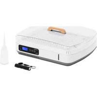
WIE-IN-110 - Egg incubator Wiesenfield - Free user manual and instructions
Find the device manual for free WIE-IN-110 Wiesenfield in PDF.


| Brand | Wiesenfield |
| Model | WIE-IN-110 |
| Product type | Egg incubator |
| Use | Domestic |
| Rated voltage / frequency | 230 V~ / 50 Hz |
| Rated power | 80 W |
| Maximum capacity (bird eggs) | 80 eggs |
| Maximum capacity (chicken eggs) | 35 eggs |
| Maximum capacity (goose eggs) | 8 eggs |
| Maximum capacity (duck eggs) | 24 eggs |
| Dimensions (W×D×H) | 360 × 440 × 160 mm |
| Weight | 3 kg |
| Material | Plastic |
| Main functions | Temperature regulation, humidity control, automatic egg turning, temperature and water level alarms, sensor calibration |
| Temperature range | 30 °C to 39.5 °C (factory setting: 38 °C) |
| Adjustable humidity | Yes (factory setting: 45%) |
| Water tank | Max. capacity 2000 ml, with low level alarm |
| Protection class | II (double insulation) |
| Maintenance and cleaning | Clean with a soft, slightly damp cloth, do not immerse, dry completely after cleaning |
| Safety | Automatic shutdown in case of fault, original plug, do not use with a damaged cable, keep out of reach of children |
| Spare parts and repairability | Repairs only by authorized service, use of original parts |
| General information | Manual included, recycling at end of life, indoor use only |
Frequently Asked Questions - WIE-IN-110 Wiesenfield
User questions about WIE-IN-110 Wiesenfield
0 question about this device. Answer the ones you know or ask your own.
Ask a new question about this device
Download the instructions for your Egg incubator in PDF format for free! Find your manual WIE-IN-110 - Wiesenfield and take your electronic device back in hand. On this page are published all the documents necessary for the use of your device. WIE-IN-110 by Wiesenfield.
USER MANUAL WIE-IN-110 Wiesenfield
3.3.3. Wasserstandskontrollfenster
3.3.5. Schlupfzeit
This User Manual has been translated for your convenience using machine translation. Reasonable efforts have been made to provide an accurate translation; however, no automated translation is perfect nor is it intended to replace human translators. The official User Manual is the English version. Any discrepancies or differences created in the translation are not binding and have no legal effect for compliance or enforcement purposes. If any questions arise related to the accuracy of the information contained in the User Manual, please refer to the English version of those contents which is the official version.
Technical data
| Parameter description Parameter value | |
| Product name | Egg incubator |
| Model | WIE-IN-110 |
| Rated voltage [V~] / frequency [Hz] | 230/50 |
| Rated power [W] | 80 |
| Maximum number of bird eggs | 80 |
| Maximum number of hen eggs | 35 |
| Maximum number of goose eggs | 8 |
| Maximum number of duck eggs | 24 |
| Dimensions [width x depth x height; mm] | 360 x 440 x 160 |
| Weight [kg] | 3 |
1. General description
The user manual is designed to assist in the safe and trouble-free use of the device. The product is designed and manufactured in accordance with strict technical guidelines, using state-of-the-art technologies and components. Additionally, it is produced in compliance with the most stringent quality standards.
DO NOT USE THE DEVICE UNLESS YOU HAVE THOROUGHLY READ AND UNDERSTOOD THIS USER MANUAL.
To increase the product life of the device and to ensure trouble-free operation, use it in accordance with this user manual and regularly perform maintenance tasks. The technical data and specifications in this user manual are up to date. The manufacturer reserves the right to make changes associated with quality improvement. The device is designed to reduce noise emission risks to a minimum, taking into account technological progress and noise reduction opportunities.
Legend


The product satisfies the relevant safety standards.
Read instructions before use.
The product must be recycled.
WARNING! or CAUTION! or REMEMBER! Applicable to the given situation.
(general warning sign)
Class II protection device with double insulation.
Only use indoors.

PLEASE NOTE! Drawings in this manual are for illustration purposes only and in some details may differ from the actual product.
2. Usage safety

ATTENTION! Read all safety warnings and all instructions. Failure to follow the warnings and instructions may result in electric shock, fire and/or serious injury or even death.
The terms "device" or "product" are used in the warnings and instructions to refer to:
Egg incubator
2.1. Electrical safety
a) The plug must fit the socket. Do not modify the plug in any way. Using original plugs and matching sockets reduces the risk of electric shock.
b) Avoid touching earthed elements such as pipes, heaters, boilers and refrigerators. There is an increased risk of electric shock if the earthed device is exposed to rain, comes into direct contact with a wet surface or is operating in a damp environment. Water getting into the device increases the risk of damage to the device and of electric shock.
c) Do not touch the device with wet or damp hands.
d) Use the cable only for its designated use. Never use it to carry the device or to pull the plug out of a socket. Keep the cable away from heat sources, oil, sharp edges or moving parts. Damaged or tangled cables increase the risk of electric shock.
e) If using the device in a damp environment cannot be avoided, a residual current device (RCD) should be applied. The use of an RCD reduces the risk of electric shock.
f) Do not use the device if the power cord is damaged or shows obvious signs of wear. A damaged power cord should be replaced by a qualified electrician or the manufacturer's service centre.
g) ATTENTION! DANGER TO LIFE! While cleaning, never immerse the device in water or other liquids.
2.2. Safety in the workplace
a) Make sure the workplace is clean and well lit. A messy or poorly lit workplace may lead to accidents. Try to think ahead, observe what is going on and use common sense when working with the device.
b) Do not use the device in a potentially explosive environment, for example in the presence of flammable liquids, gases or dust. The device generates sparks which may ignite dust or fumes.
c) If you discover damage or irregular operation, immediately switch the device off and report it to a supervisor without delay.
d) If there are any doubts as to the correct operation of the device, contact the manufacturer's support service.
e) Only the manufacturer's service point may repair the device. Do not attempt any repairs independently!
f) In case of fire, use a powder or carbon dioxide (CO2) fire extinguisher (one intended for use on live electrical devices) to put it out.
g) Please keep this manual available for future reference. If this device is passed on to a third party, the manual must be passed on with it.
h) Keep packaging elements and small assembly parts in a place not available to children.
i) Keep the device away from children and animals.

Remember! When using the device, protect children and other bystanders.
2.3. Personal safety
a) Do not use the device when tired, ill or under the influence of alcohol, narcotics or medication which can significantly impair the ability to operate the device.
b) The device can be handled only by physically fit persons who are capable of handling it, properly trained, familiar with this manual and trained within the scope of occupational health and safety.
c) To prevent the device from accidentally switching on, make sure the switch is on the OFF position before connecting to a power source.
d) The device is not a toy. Children must be supervised to ensure that they do not play with the device.
2.4. Safe device use
a) Do not use the device if the ON/OFF switch does not function properly (does not switch the device on and off). Devices which cannot be switched on and off using the ON/OFF switch are hazardous, should not be operated and must be repaired.
b) Disconnect the device from the power supply before commencement of adjustment, cleaning and maintenance. Such a preventive measure reduces the risk of accidental activation.
c) When not in use, store in a safe place, away from children and people not familiar with the device who have not read the user manual. The device may pose a hazard in the hands of inexperienced users.
d) Keep the device in perfect technical condition. Before each use check for general damage and especially check for cracked parts or elements and for any other conditions which may impact the safe operation of the device. If damage is discovered, hand over the device for repair before use.
e) Keep the device out of the reach of children.
f) Device repair or maintenance should be carried out by qualified persons, only using original spare parts. This will ensure safe use.
g) To ensure the operational integrity of the device, do not remove factory-fitted guards and do not loosen any screws.
h) Do not touch articulated parts or accessories unless the device has been disconnected from the power source.
i) Do not move, adjust or rotate the device in the course of work.
j) Clean the device regularly to prevent stubborn grime from accumulating.
k) The device is not a toy. Cleaning and maintenance may not be carried out by children without supervision by an adult person.
I) It is forbidden to interfere with the structure of the device in order to change its parameters or construction.
m) Keep the device away from sources of fire and heat.
n) Before the first use, always verify that the device is complete and that all movable elements that may affect the safety of embryonated eggs or chicks, e.g. the fans, are protected by covers.
o) Do not cover the device when in use.
p) Warning: Risk of fire.
q) Some parts of this appliance can get very hot. To avoid injury, be careful when touching these surfaces.
r) Inspect the water level in the egg incubator regularly. Fill with warm water.
s) Use a measuring cup when filling with water.
t) Always disconnect the egg incubator from power when topping up with water and when not in use.
u) In order to improve incubation observe generally accepted breeding principles.

ATTENTION! Despite the safe design of the device and its protective features, and despite the use of additional elements protecting the operator, there is still a slight risk of accident or injury when using the device. Stay alert and use common sense when using the device.
3. Use guidelines
The egg incubator is designed for incubating fertile avian eggs. The incubator keeps the eggs at the correct temperature and humidity required for the embryo to develop and hatch.
The product is intended for home use only.
The user is liable for any damage resulting from unintended use of the device.
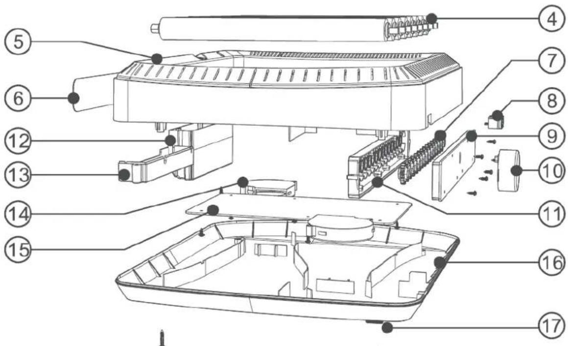
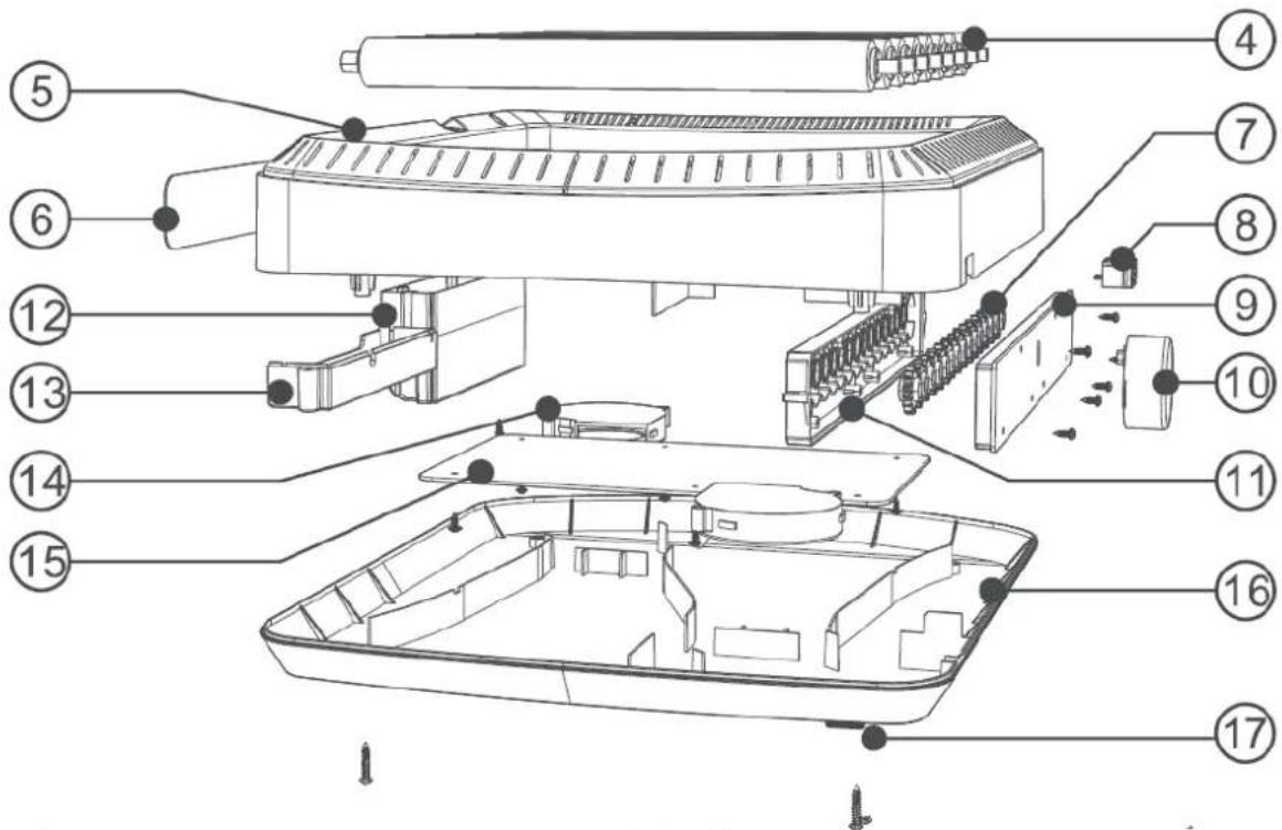
3.1. Device description
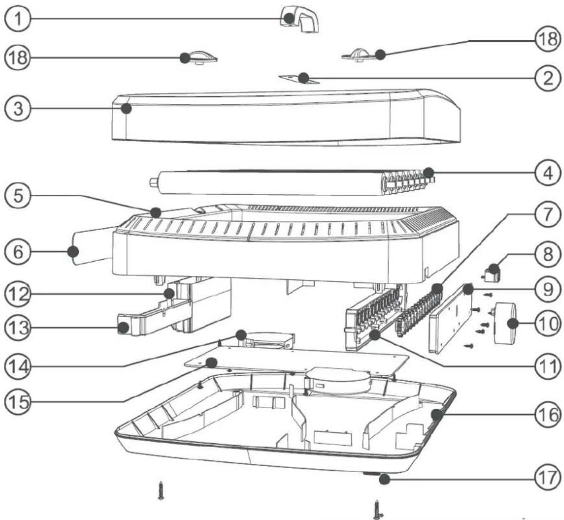
| 1. | Handle | 2. | Label |
| 3. | Cover | 4. | Roller egg tray |
| 5. | Middle frame | 6. | Control panel |
| 7. | Gear | 8. | Power socket |
| 9. | Gearbox base | 10. | Motor |
| 11. | Gearbox cover | 12. | Water tank |
| 13. | PCB cover | 14. | Fan |
| 15. | Heater | 16. | Base |
| 17. | Drain plug | ||
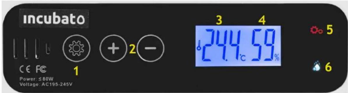
Control panel:
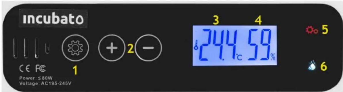
1 - Settings button.
2 - Buttons for changing the set values.
3 – Current temperature display.
4 – Current humidity display.
5 - Setting indicator light.
6 - Low water level alarm light.
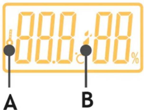
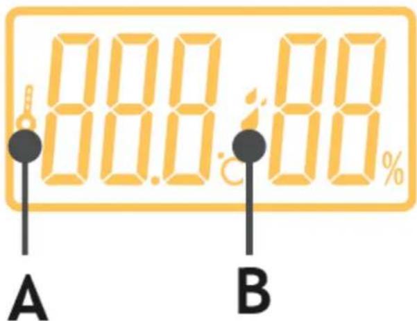
A – the indicator light is on when the device heats up
B – the indicator light is on when the device is humidifying
3.2. Preparing for use
APPLIANCE LOCATION
The temperature of environment must not be higher than 40° C and the relative humidity should be less than 85%. Ensure good ventilation in the room in which the device is being used. There should be at least 10 cm distance between each side of the device and the wall or other objects. The device should always be used when positioned on an even, stable, clean, fireproof and dry surface, and be out of the reach of children and persons with limited mental and sensory functions. Position the device such that you always have access to the power plug. The power cord connected to the appliance must be properly grounded and correspond to the technical details on the product label.
Disassemble the device and all its components and clean them before the first use.
3.3. Assembling the device
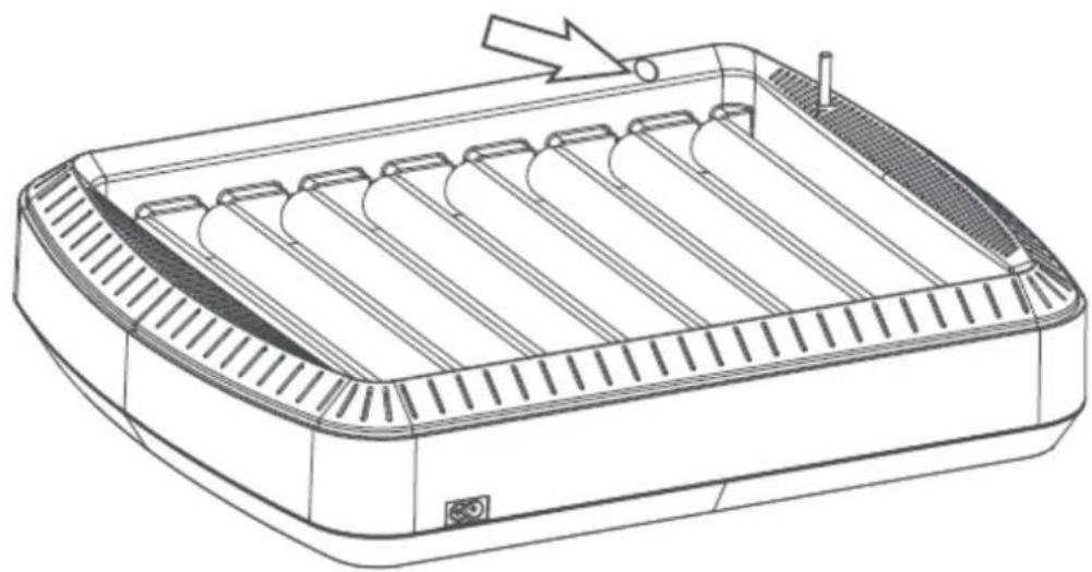
3.3.1. Vent
Adjust the grey vent button, wait 2-3 hours until the humidity reading is stable, close the vent to increase humidity or open the vent to decrease the humidity.
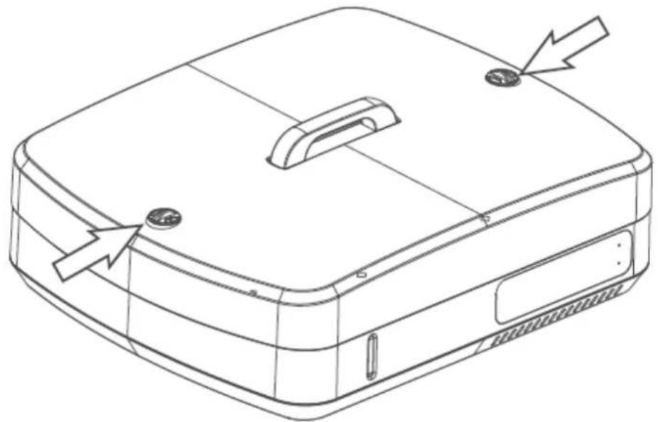
3.3.2. Water addition hole
Remember to add water when use the machine in first time; approx. 2000ml max.
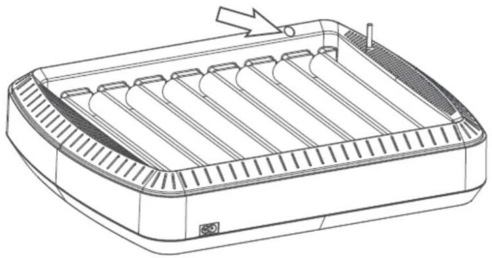
3.3.3. Water level check window
The device will alarm when there is no water; in this case, water should be refilled.
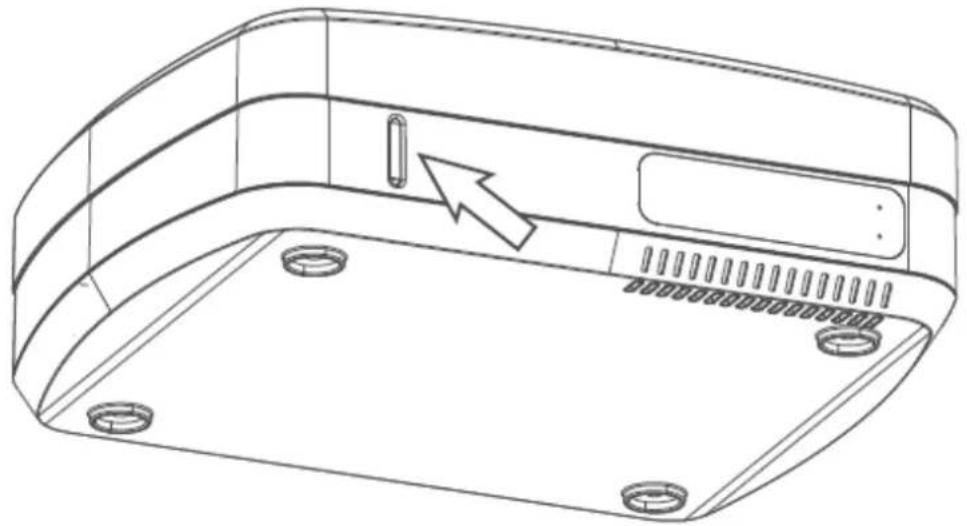
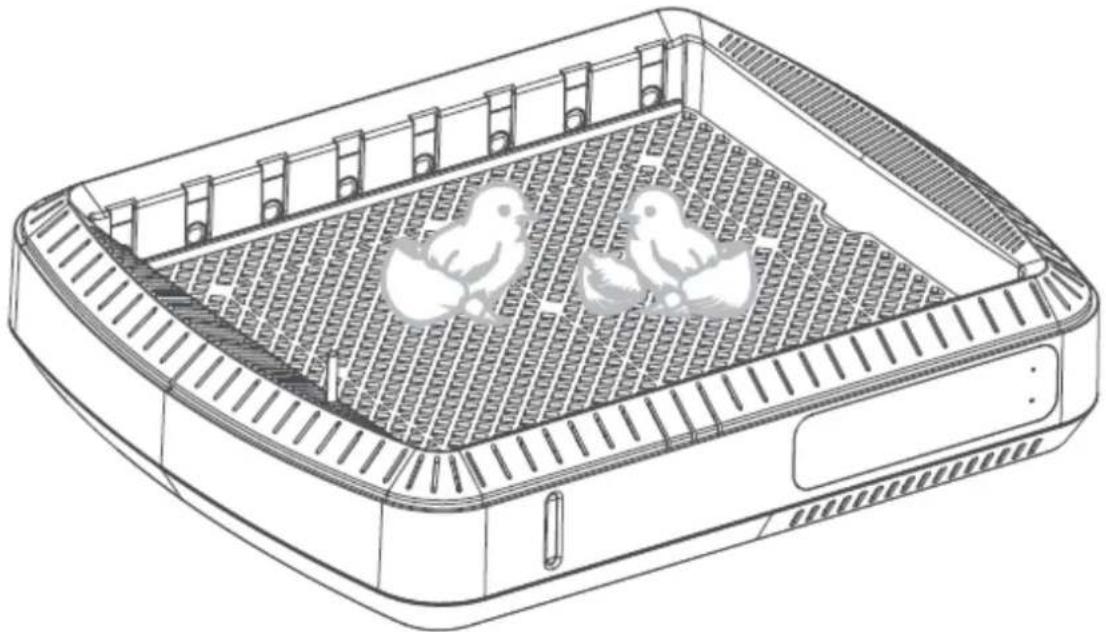
3.3.4. How to mount egg trays
Note that the two ends of the egg tray roll are different sizes.
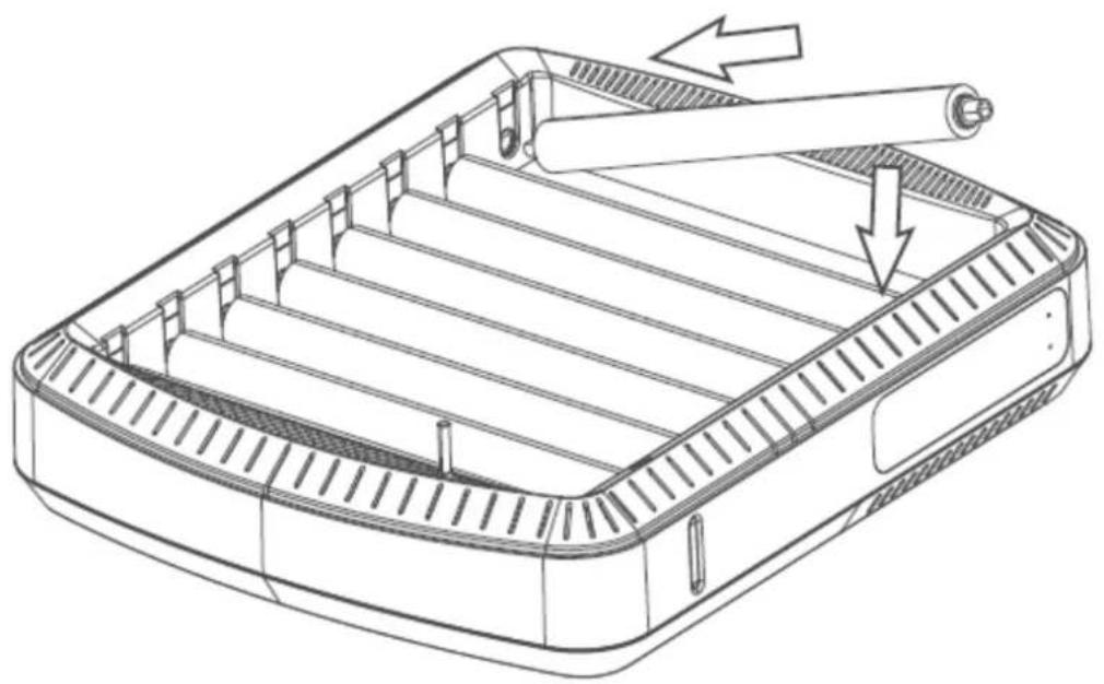
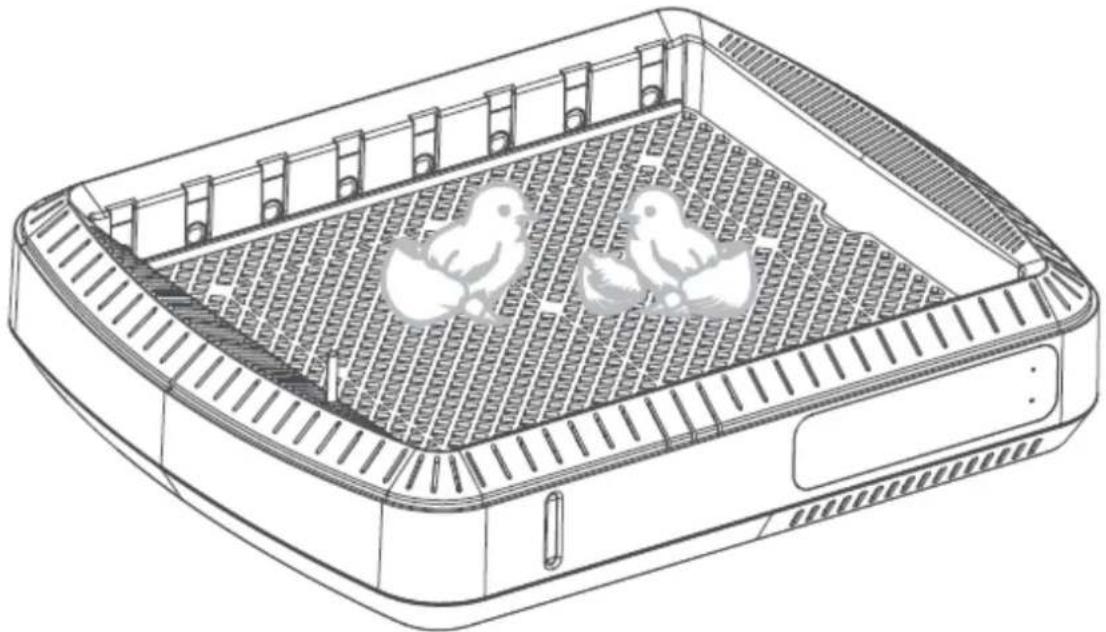
3.3.5. Hatching period
Remove the roller egg tray from the incubator, put the grid back for hatching.
3.3.6. After finish hatching
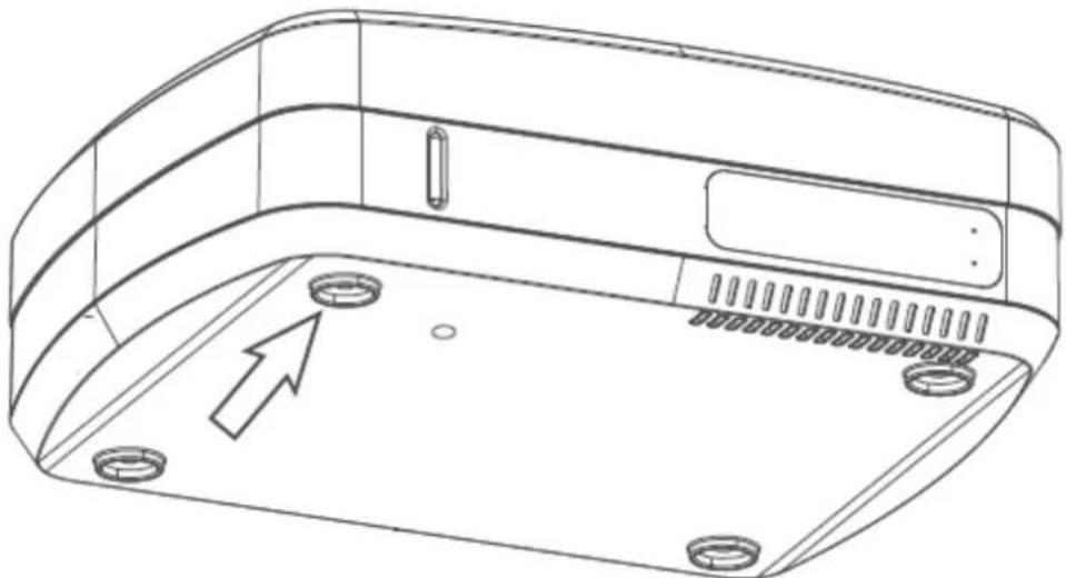
Pull out of drain plug, drain the remaining water, make the machine clean and dry for next incubation.
3.4. Device use
3.4.1. Temperature setting
Press Settings button (1) once, press buttons "+" or "-" (2) to set required temperature, press Settings button (1) to save it. The factory setting temperature is 38° C/ 100° F.
3.4.2. Humidity Setting (AS)
Long press Settings button (1) for 3 seconds, press buttons "+" or "-" (2) until "AS" is illustrated on the temperature display screen, press Settings button (1) to confirm AS, press buttons "+" or "-" (2) to set required humidity. Factory setting is 45.
It is not recommended to change the following parameters:
3.4.3. Setting Temperature Alarm (AL, AH)
a) Setting low temperature alarm (AL): Long press Settings button (1) for 3 seconds, press buttons "+" or "-" (2) until "AL" is illustrated on the temperature display screen, press Settings button (1) to confirm AL, press buttons "+" or "-" (2) to set required low temperature alarm value. Factory setting is 1°C / 2°F .
b) Setting high temperature alarm (AH): Long press Settings button (1) for 3 seconds, press buttons "+" or "-" (2) until "AH" is illustrated on the temperature display screen, press Settings button (1) to confirm AL, press buttons "+" or "-" (2) to set required low temperature alarm value. Factory setting is 1°C/2°F.
3.4.4. Calibrating Temperature Sensor Reading (CA)
Long press Settings button (1) for 3 seconds, press buttons "+" or "-" (2) until the code "CA" is illustrated on the temperature display screen, press Settings button (1) to confirm CA, press buttons "+" or "-" (2) to adjust the correct temperature. Factory setting is 0.
3.4.5. Setting Higher Temperature Limit (HS)
Long press Settings button (1) for 3 seconds, press buttons "+" or "-" (2) until the code "HS" is illustrated on the temperature display screen, press Settings button (1) to confirm the code HS, press buttons "+" or "-" (2) to adjust the correct limit setting range. Factory setting is 39.5°C/103°F.
3.4.6. Setting Lower Temperature Limit (LS)
Long press Settings button (1) for 3 seconds, press buttons "+" or "-" (2) until the code "LS" is illustrated on the temperature display screen, press Settings button (1) to confirm the code LS, press buttons "+" or "-" (2) to adjust the correct limit setting range. Factory setting is 30.
3.4.7. Restore Factory Settings
Press the "+" and "-" buttons (2) simultaneously for more than 3 seconds until a tone sounds and the 9-0 countdown appears on the screen.
REMARKS:
a) Add water every day (it depends on the environment and the amount of water inside the machine).
b) Do not open the lid frequently.
c) Fertilized eggs are required for hatching.
d) There is a drain plug on the bottom of the machine, please do not discard.
e) In hatching period, remove the rolling trays from the incubator and put the white grid into the machine and place the eggs on the grid.
How to choose eggs before hatching?
a) The eggs must be fresh. Generally, the fertilized eggs within 4-7 days after laying. And do not put them into the refrigerator or wash.
b) Take out the rotation shaft and place the eggs in the hatching grid after 18-day hatching period.
What are the precautions for hatching?
c) Proper operation and careful observation are required during the incubation, such as: add water to the machine every 1 to 2 days (it depends on the environment and the amount of water inside the machine).
d) Place the unit in foam if the ambient temperature exceeds 20° C/68°F for better heat retention.
e) Do not open the lid frequently during incubation, it'll make the unbroken eggshell dry out and difficult to be broken.
f) Check the development of eggs timely during the incubation period:
i. The 1st time to test egg (Day 5th-6th): mainly to check the fertilization of the eggs, select the unfertilized eggs, scattered yellow eggs, dead eggs.
ii. The 2nd time to test egg (Day 11th-12th): mainly to check the development of egg embryo, the well-developed embryo is enlarged, with blood vessels inside, and the air chamber is large and sharply demarcated.
iii. The 3rd time to test egg (Day 16th-17th): Light from the pointed side, a well-developed embryo is larger, meanwhile full of egg, and no light in most places. If it's a dead egg, the blood vessels in the egg are blurred, Parts yellow near the air chamber, the boundary between the egg and the air chamber is not clear.
g) Hatching period (Day 19th-21th): It's into hatching period once cracks appeared on the eggshell. Meanwhile increase the humidity to ensure the eggshell soft enough to break, and decrease the temperature into 37 -37.5°C/98-99°F.
How to better preserve the machine after hatching?
Clean up and air-dry the machine timely after using, to prevent the electronic components from being damaged by internal moisture of the machine.
Suggested temperature and humidity for different species:
| Egg Type | Hatching Days | Setter period | Hatcher period | Egg weight [g] |
| Chicken eggs | 21 | 38.0°C(100°F) / 55-70 | 37.5°C(99°F) / 60-85 | 50-60 |
| Duck eggs | 28 | 37.8°C(100°F) / 60-75 | 37.3°C(99°F) / 65-85 | 80-100 |
| Goose eggs | 30 | 37.6°C(99°F) / 65-80 | 37.1°C(98°F) / 65-85 | 100-120 |
3.5. Cleaning and maintenance
a) Unplug the mains plug and allow the device to cool completely before each cleaning, adjustment or replacement of accessories, or if the device is not being used.
b) Use only non-corrosive cleaners to clean the surface.
c) After cleaning the device, all parts should be dried completely before using it again.
d) Store the unit in a dry, cool place, free from moisture and direct exposure to sunlight.
e) Do not spray the device with a water jet or submerge it in water.
f) Do not allow water to get inside the device through vents in the housing of the device.
g) Clean the vents with a brush and compressed air.
h) The device must be regularly inspected to check its technical efficiency and spot any damage.
i) Use a soft, damp cloth for cleaning.
j) Do not use sharp and/or metal objects for cleaning (e.g. a wire brush or a metal spatula) because they may damage the surface material of the appliance.
k) Do not clean the device with an acidic substance, agents of medical purposes, thinners, fuel, oils or other chemical substances because it may damage the device.
DISPOSING OF USED DEVICES:
Do not dispose of this device in municipal waste systems. Hand it over to an electric and electrical device recycling and collection point. Check the symbol on the product, instruction manual and packaging. The plastics used to construct the device can be recycled in accordance with their markings. By choosing to recycle you are making a significant contribution to the protection of our environment.
Contact local authorities for information on your local recycling facility.

1 - Knappen Indstillinger.
6 - Alarmlampe for lav vandstand.
APPARATETS PLACERING
3.4. Brug af enhed
3.4.1. Indstilling af temperatur
Tryk én gang på knappen Settings (1), tryk på knapperne "+" eller "-" (2) for at indstille den ønskede temperatur, og tryk på knappen Settings (1) for at gemme den. Den fabriksindstillede temperatur er 38°C/100°F.
3.3.3. Vesitason tarkistusikkuna
| 1. | Handvat | 2. | Etiket |
| 3. | Deksel | 4. | Rol eierrekje |
| 5. | Middelste frame | 6. | Besturingspaneel |
| 7. | Versnelling | 8. | Stopcontact |
| 9. | Basis versnellingsbak | 10. | Motor |
| 11. | Versnellingsbak deksel | 12. | Watertank |
| 13. | PCB-afdekking | 14. | Ventilator |
| 15. | Verwarming | 16. | Basis |
17. Aftapplug
Bedieningspaneel
1 - Knop Instellingen.
PLAATS VAN HET APPARAAT
3.3.4. Hoe eiertrays te monteren
3.3.5. Broedperiode
| 1. | Händtak | 2. | Merkelapp |
| 3. | Lokk | 4. | Rull eggebrett |
| 5. | Mellomramme | 6. | Styrepanel |
| 7. | Utstyr | 8. | Stikkontakt |
| 9. | Girkassesokkel | 10. | Motor |
| 11. | Girkassedeksel | 12. | Vanntank |
| 13. | PCB deksel | 14. | Vifte |
| 15. | Varmeapparat | 16. | Ramme |
| 17. | Dreneringsplugg | ||
Betjeningspanel:
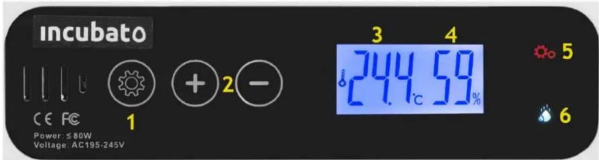
1 – Innstillinger-knapp.
2 – Knapper for å endre innstilte verdier.
3.3.4. Hvordan montere eggebrett
3.3.5. Klekkeperiode
3.3.6. Etter ferdig klekking
| 1. | Handtag | 2. | Märka |
| 3. | Lock | 4. | Rull äggbricka |
| 5. | Mellersta ram | 6. | Kontrollpanel |
| 7. | Redskap | 8. | Nätadapteranslutning |
| 9. | Växellådans bas | 10. | Motor |
| 11. | Växellådans lock | 12. | Vattentank |
| 13. | PCB lock | 14. | Fläkt |
| 15. | Värmeelement | 16. | Bas |
| 17. | Avtappningsplugg | ||
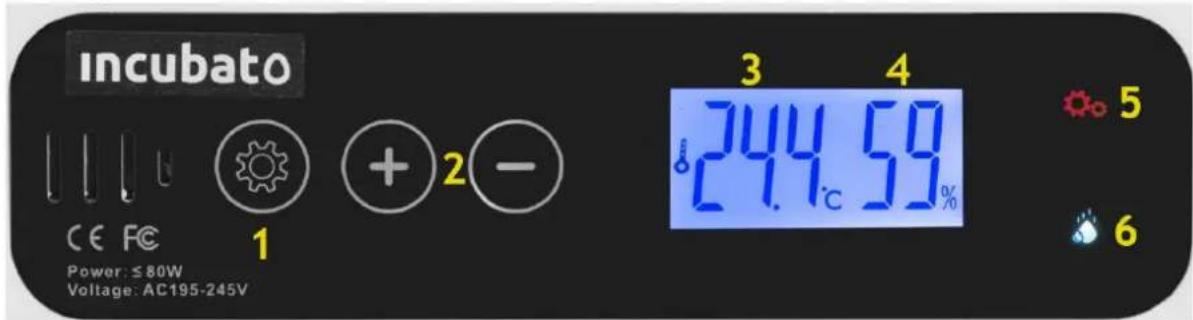
Kontrollpanel:
APPARATENS PLACERING
3.3.3. Vattennivåkontrollfönster
3.3.4. Como montar bandejas de ovos
1 - tlačidlo Nastavenia.
A – kontrolka svieti, ked' sa zariadenie zahrieva
3.3.2. Otvor na pridávanie vody
Pri prvom použití stroja nezabudnite pridat' vodu; približne. 2000 ml max.
3.3.3. Okienko na kontrolu hladiny vody
3.3.5. Obdobie liahnutia
Vyberte valček na vajcia z inkubátora, vložte mriežku spät na vyliahnutie.
For the disposal of the device please consider and act according to the national and local rules and regulations.
CONTACT
expondo Polska sp. z o.o. sp. k.

- WASSERSTANDSKONTROLLFENSTER
- SCHLUPFZEIT
- GENERAL DESCRIPTION
- DO NOT USE THE DEVICE UNLESS YOU HAVE THOROUGHLY READ AND UNDERSTOOD THIS USER MANUAL
- LEGEND
- USAGE SAFETY
- ELECTRICAL SAFETY
- SAFETY IN THE WORKPLACE
- PERSONAL SAFETY
- SAFE DEVICE USE
- USE GUIDELINES
- DEVICE DESCRIPTION
- CONTROL PANEL
- PREPARING FOR USE
- APPLIANCE LOCATION
- ASSEMBLING THE DEVICE
- VENT
- WATER ADDITION HOLE
- WATER LEVEL CHECK WINDOW
- HOW TO MOUNT EGG TRAYS
- HATCHING PERIOD
- AFTER FINISH HATCHING
- DEVICE USE
- TEMPERATURE SETTING
- HUMIDITY SETTING (AS)
- SETTING TEMPERATURE ALARM (AL, AH)
- CALIBRATING TEMPERATURE SENSOR READING (CA)
- SETTING HIGHER TEMPERATURE LIMIT (HS)
- SETTING LOWER TEMPERATURE LIMIT (LS)
- RESTORE FACTORY SETTINGS
- REMARKS
- HOW TO CHOOSE EGGS BEFORE HATCHING
- HOW TO BETTER PRESERVE THE MACHINE AFTER HATCHING
- CLEANING AND MAINTENANCE
- DISPOSING OF USED DEVICES
- APPARATETS PLACERING
- BRUG AF ENHED
- INDSTILLING AF TEMPERATUR
- VESITASON TARKISTUSIKKUNA
- AFTAPPLUG
- BEDIENINGSPANEEL
- PLAATS VAN HET APPARAAT
- HOE EIERTRAYS TE MONTEREN
- BROEDPERIODE
- BETJENINGSPANEL
- HVORDAN MONTERE EGGEBRETT
- KLEKKEPERIODE
- ETTER FERDIG KLEKKING
- APPARATENS PLACERING
- VATTENNIVÅKONTROLLFÖNSTER
- COMO MONTAR BANDEJAS DE OVOS
- OTVOR NA PRIDÁVANIE VODY
- OKIENKO NA KONTROLU HLADINY VODY
- OBDOBIE LIAHNUTIA
- CONTACT
Brand : Wiesenfield
Model : WIE-IN-110
Category : Egg incubator