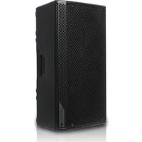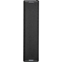
Ingenia IG5T - Speaker DB Technologies - Free user manual and instructions
Find the device manual for free Ingenia IG5T DB Technologies in PDF.


User questions about Ingenia IG5T DB Technologies
0 question about this device. Answer the ones you know or ask your own.
Ask a new question about this device
Download the instructions for your Speaker in PDF format for free! Find your manual Ingenia IG5T - DB Technologies and take your electronic device back in hand. On this page are published all the documents necessary for the use of your device. Ingenia IG5T by DB Technologies.
USER MANUAL Ingenia IG5T DB Technologies
2-way professional loudspeaker
natural_image
Line drawing of a rectangular industrial device with labeled components (ICSTR, Technology) and internal compartments (no text or symbols beyond labels)USER MANUAL - Section 1.
The warnings in this manual must be observed in conjunction with the "USER MANUAL - Section 2".
According to the standards EN 55032 and 55035 this is a class B equipment, designed and suitable to operate in residential environments.
FCC CLASS B STATEMENT ACCORDING TO TITLE 47, PART 15, SUBPART B, §15.105
This equipment has been tested and found to comply with the limits for a Class B digital device, pursuant to part 15 of the FCC Rules.
These limits are designed to provide reasonable protection against harmful interference in a residential installation.
This equipment generates, uses and can radiate radio frequency energy and, if not installed and used in accordance with the instructions, may cause harmful interference to radio communications.
However, there is no guarantee that interference will not occur in a particular installation. If this equipment does cause harmful interference to radio or television reception, which can be determined by turning the equipment off and on, the user is encouraged to try to correct the interference by one or more of the following measures:
- Reorient or relocate the receiving antenna.
- Increase the separation between the equipment and receiver.
- Connect the equipment into an outlet on a circuit different from that to which the receiver is connected.
- Consult the dealer or an experienced radio/TV technician for help.
Changes or modifications not expressly approved by the party responsible for compliance could void the user's authority to operate the equipment.
WARNING
Make sure that the loudspeaker is securely installed in a stable position to avoid any injuries or damages to persons or properties.
For safety reasons do not place one loudspeaker on top of another without proper fastening systems. Before hanging the loudspeaker check all the components for damages, deformations, missing or damaged parts that may compromise safety during installation. If you use the loudspeakers outdoor avoid spots exposed to bad weather conditions.
Contact dB Technologies for accessories to be used with speakers. dBTechnologies will not accept any responsibility for damages caused by inappropriate accessories or additional devices.
Features, specification and appearance of products are subject to change without notice. dBTechnologies reserves the right to make changes or improvements in design or manufacturing without assuming any obligation to change or improve products previously manufactured.
IG5TR
Cod. 420120452 REV. 1.1
IMPORTANT SAFETY INSTRUCTIONS:
- Read these instructions
- Keep these instructions.
- Heed all warnings.
- Follow all instructions.
- Do not use this apparatus near water.
-
Clean only with dry cloth.
-
Do not block any ventilation openings. Install in accordance with the manufacturer's instructions.
-
Do not install near any heat sources such as radiators, heat registers, stoves, or other apparatus (including amplifiers) that produce heat.
-
Do not defeat the safety purpose of the polarized or grounding-type plug. A polarized plug has two blades with one wider than the other. A grounding type plug has two blades and a third grounding prong. The wide blade or the third prong are provided for your safety. If the provided plug does not fit into your outlet, consult an electrician for replacement of the obsolete outlet.
-
Protect the power cord from being walked on or pinched particularly at plugs, convenience receptacles, and the point where they exit from the apparatus.
-
Only use attachments /accessories specified by the manufacturer.

- Use only with the cart, stand tripod, bracket, or table specified by the manufacturer, or sold with the apparatus. When a cart is used, use caution, when moving the cart/apparatus combination to avoid injury from tip-over.
- Unplug this apparatus during lightning storms or when unused for long periods of time.
- Refer all servicing to qualified service personnel. Servicing is required when the apparatus has been damaged in any way, such as power-supply cord or plug is damaged, liquid has been spilled or objects have fallen into the apparatus has been exposed to rain or moisture, does not operate normally, or has been dropped.
ADDITIONAL SAFETY INSTRUCTIONS:
- No naked flame sources, such as lighted candles, should be placed on the apparatus
- Do not use the apparatus in tropical climates
IG5TR Cod. 420120452 REV. 1.1
ITALIANO
ENGLISH
DEUTSCH
FRANÇAIS
ESPAÑOL
IG5TR
Cod. 420120452 REV. 1.1
INDICE
2. PRIMA ACCENSIONE ....11
IL DIGITAL STEERING ....23
6. RISOLUZIONE DEI PROBLEMI....24
7. AGGIORNAMENTO DEL FIRMWARE ....24
8. SPECIFICHE TECNICHE....25
GENERALE 25
DATI ACUSTICI....25
AMPLIFICATORE 25
PROCESSORE 25
INTERFACCIA UTENTE....26
INGRESSI E USCITE 26
text_image
20° -55° 75° 90° ElectronicsIG5TR Cod. 420120452 REV. 1.1
MECCANICA
text_image
Technical diagram of an electronic device showing internal components with labeled parts C and D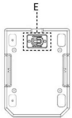
natural_image
Technical line drawing of a device housing with an internal component and labeled point E (no text or symbols beyond label)ACCESSORI
natural_image
Technical line drawing of a mechanical assembly with circular components and mounting bracket (no text or symbols)DRK-IG5TR
flybar
natural_image
Technical line drawing of a mechanical housing with internal components and mounting holes (no text or symbols)GSA-IG5TR
mouting adapter
IG5TR
Cod. 420120452 REV. 1.1
SEZIONE DI INGRESSO, USCITA E CONTROLLO
1. INGRESSO E RILANCIO DELLA CONNESSIONE DI RETE RDNet
text_image
RDNet Data In Data Out Balanced Audio Input Link USB Data Service ICSTR Status Signal Peak Function Control dB Technologies 1 2 3 4 5 6| ICSTR | Status Signal Peak | ||
| Accensione | ACCESO FISSO PER QUALCHE SECONDO | SPENTO SPENTO | |
| Utilizzo SPENTO | SIGNAL OUTPUT STATUS | COMPRESSION LIMITER STATUS | |
| Anomalia parziale LAMPEGGIO CICLICO ATTIVO SPENTO | |||
| Anomalia totale ATTIVO SPENTO LAMPEGGIO CICLICO | |||
| Connessione RDNet LAMPEGGIO SPENTO SPENTO | |||
| Display in stand-by | SPENTO LAMPEGGIO CICLICO SPENTO | ||
4. PUSH ROTARY ENCODER
7. INGRESSO E RILANCIO AUDIO ("Balanced audio")
natural_image
Diagram of two circular mechanical components with labeled ports (no text or symbols beyond numbers 8 and 9)natural_image
Hand pressing a button on a circular button with an arrow indicating rotation (no text or symbols)CONFERMA
natural_image
Simple line drawing of a hand pressing a button with an arrow indicating rotation (no text or symbols)natural_image
Simple line drawing of a hand pressing a button with an arrow indicating rotation (no text or symbols)Main Page Offline Mode
Main Page Go Offline
MENU PRESET
flowchart
graph TD
    A["MAIN MENU"] --> B["Preset"]
    B --> C["DSP Settings Info Reset"]
    C --> D["DSP Gain Delay HPF Steering"]
    D --> E["GAIN -10 dB"]
    E --> F["DSP Gain Delay HPF Steering"]
    F --> G["DELAY 10 ms 3.45 m 11.32 ft"]
    G --> H["DSP Gain Delay HPF Steering"]
    H --> I["HPF 70 Hz"]
    I --> J["DSP Gain Delay HPF Steering"]
    J --> K["STEERING +10°"]
MENU SETTINGS
flowchart
graph TD
    A["MAIN MENU"] --> B["Preset DSP"]
    B --> C["Settings Info Reset"]
    C --> D["SETTINGS Detection Standby Brightness"]
    D --> E["DETECTION Auto"]
    E --> F["Force as Unit A"]
    F --> G["DETECTION Force as Unit B"]
    G --> H["SETTINGS Detection Auto Standby Brightness"]
    H --> I["STANDBY 10 s"]
    I --> J["SETTINGS Detection Standby Brightness"]
    J --> K["BRIGHTNESS 30%"]
IG5TR
Cod. 420120452 REV. 1.1
MENU INFO
natural_image
Technical line drawing of a rectangular industrial enclosure with internal compartments and mounting brackets (no text or symbols)IG5TR
Cod. 420120452 REV. 1.1
natural_image
Technical line drawings of three vertical industrial equipment units with mounting brackets and ventilation slots (no text or symbols)IG5TR Cod. 420120452 REV. 1.1
natural_image
Technical line drawing of a rectangular industrial or electrical cabinet with two side compartments and mounting brackets (no text or symbols)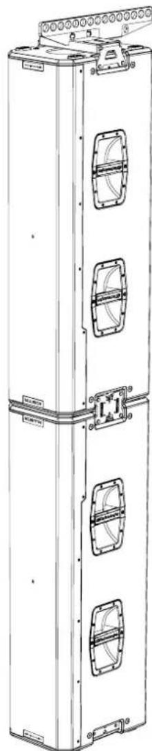
natural_image
Technical line drawing of a tall industrial cabinet with multiple side compartments and mounting brackets (no text or symbols)IG5TR
Cod. 420120452 REV. 1.1
IL DIGITAL STEERING
natural_image
Diagram of a multi-level vehicle parking or traffic structure with directional arrows indicating flow or movement (no text or symbols present)* @1 meter, free field, AES75 with Music-Noise
** @1 meter, free field, SPL Max Peak with Pink Noise (CF=4)
IG5TR Cod. 420120452 REV. 1.1
INTERFACCIA UTENTE
1. GENERAL INFORMATIONS ....30
WELCOME! 30
INTRODUCTORY OVERVIEW....30
USER REFERENCE....30
MECHANICAL AND ACOUSTICAL FEATURES....31
SIZE AND WEIGHT 31
ACOUSTIC FEATURES 31
MECHANICS 32
ACCESSORIES 32
FEATURES OF THE AMPLIFIER AND CONTROL SECTION....33
INPUT, OUTPUT AND CONTROL SECTION 34
POWER SUPPLY UNIT SECTION 35
2. FIRST POWER-UP 35
PACKAGE CONTENTS 35
INSTALLATION....36
AUDIO SIGNAL CONNECTION AND LINK 36
POWER SUPPLY CONNECTION AND LINK 36
RDNET SIGNAL CONNECTION AND LINK 36
3. REMOTE CONTROL....37
4. CONTROL PANEL AND SETTING MENU ....38
ACCESSING THE MENUS....38
MAIN PAGE....39
PRESET MENU 40
DSP MENU 41
SETTINGS MENU 42
INFO MENU 43
RESET MENU 43
5. INSTALLATION EXAMPLES....44
STACKED INSTALLATION....45
FLOWN INSTALLATION 46
DIGITAL STEERING 47
6. TROUBLESHOOTING 48
7. FIRMWARE UPDATES......48
8. SPECIFICATIONS......49
GENERAL INFORMATION 49
ACOUSTICAL DATA....49
AMPLIFIER....49
PROCESSOR 49
USER INTERFACE 50
INPUTS AND OUTPUTS....50
POWER SUPPLY SPECIFICATIONS (ABSORPTION) 50
DIMENSIONS 51
1. GENERAL INFORMATION
WELCOME!
Thanks for purchasing a product designed and developed in Italy by dBTechnologies! These professional active loudspeakers incorporate years of experience and innovation in the field of sound reinforcement, using state-of-the-art acoustic and material research solutions.
PRODUCT OVERVIEW
IG5TR is the new vertical two-way active loudspeaker of the INGENIA series. It features a new Class D amplifier delivering 1600 W RMS, three neodymium woofers with 10" magnets (2.5" voice coil) and a neodymium compression driver with 1.4" output (3" voice coil); the asymmetrical waveguide horn optimises vertical coverage across the entire frequency spectrum, improving sound distribution even in a two-loudspeaker stacked configuration.
Its main features include:
- high audio power
- simple and fast configuration
- main functions manageable via display using an encoder
- remote control via AURORA Net software
• digital steering controlled by powerful internal DSP
USER REFERENCE
To make the most of your IG5TR loudspeaker, we recommend that you:
- read the quick start user manual included in the package and this user manual thoroughly and keep this manual during the whole life of the product.
- register your product at http://www.dbtechnologies.com under "SUPPORT".
- keep proof of purchase and WARRANTY (User manual "section 2").
IG5TR
Code 420120452 REV. 1.1
MECHANICAL AND ACOUSTICAL FEATURES
SIZE AND WEIGHT
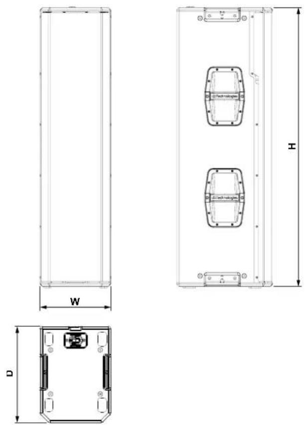
IG5TR has been designed with particular attention to the optimisation of weight and size. It weighs 35 kg. Sizes are: 280 mm (W) x 1100 (H) x 380 mm (D)
SOUND COVERAGE
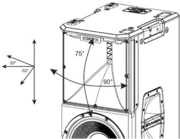
The particular opening of the horn, shown in the figure, guarantees excellent sound coverage performance in both indoor and outdoor settings. By using two loudspeakers on top of each other, it is also possible to control total coverage with digital steering. So, whilst installing two loudspeakers vertically, the effect of a single slanting loudspeaker with all the associated directivity advantages can be achieved.
text_image
20° -55° 75° 90°IG5TR Code 420120452 REV. 1.1
MECHANICS
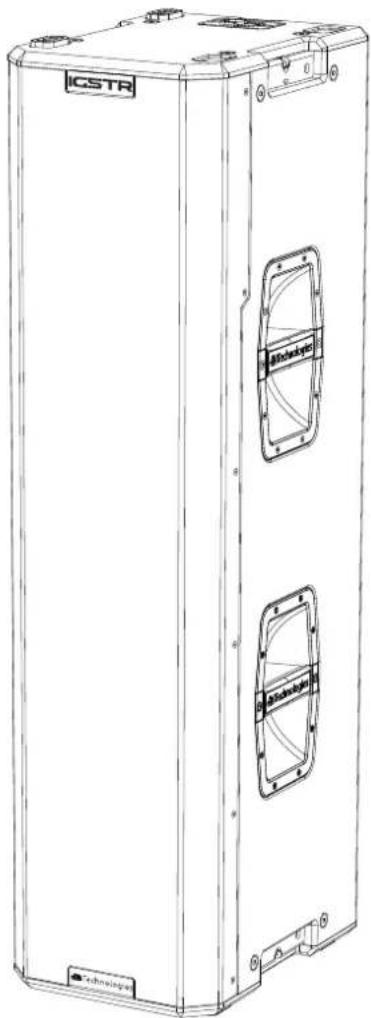
The ergonomics and quick assembly of the IG5TR loudspeakers are ensured by:
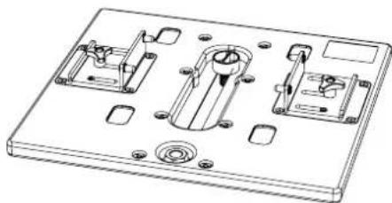
A. mechanical attachment points for accessories
B. handle
C. housing for LP-1 connection bracket (included)
D. frame for rain cover attachment
E. IR port
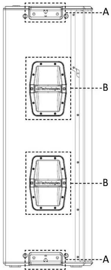
text_image
A B B A allTechnologies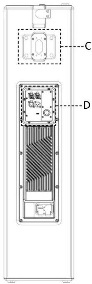
text_image
Technical diagram of an electronic device showing internal components with labeled parts C and D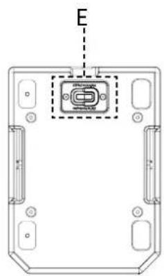
text_image
EACCESSORIES
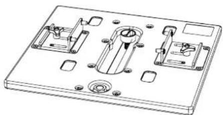
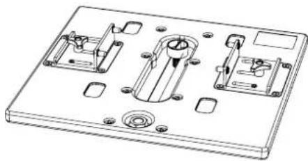
For quick assembly of the IG5TR loudspeakers, the following accessories are provided:
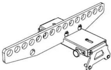
natural_image
Technical line drawing of a mechanical assembly with circular components and a vehicle (no text or symbols)DRK-IG5TR
flybar
natural_image
Technical line drawing of a mechanical housing with internal components (no text or symbols)GSA-IG5TR
mounting adapter
IG5TR
Code 420120452 REV. 1.1
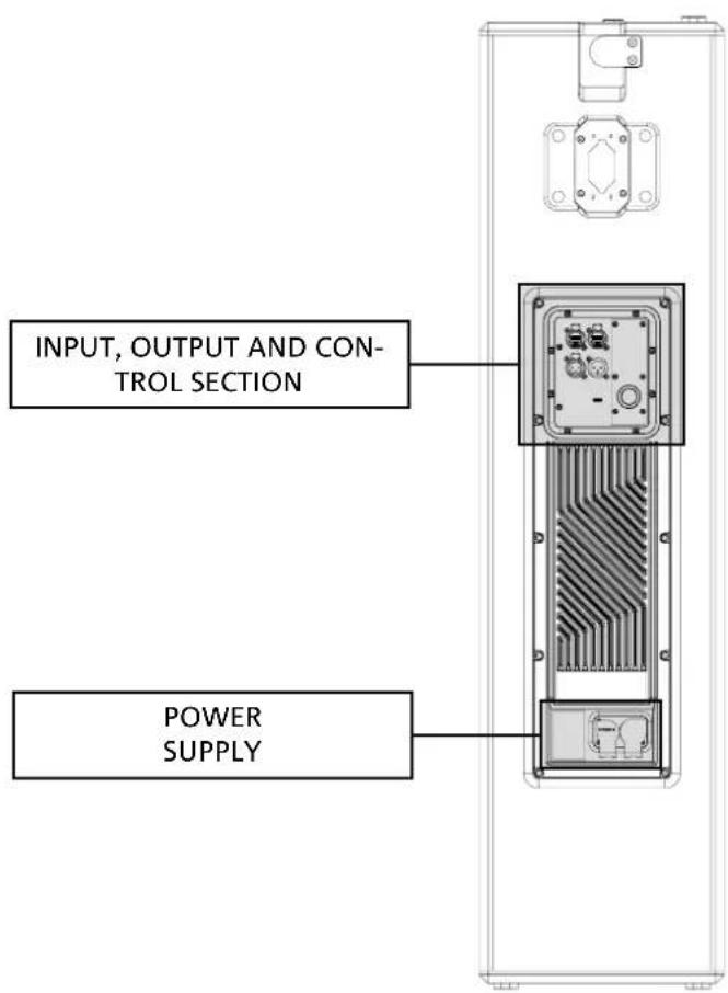
FEATURES OF THE AMPLIFIER AND CONTROL SECTIONS
The latest-generation class D digital amplifier is the heart of the IG5TR loudspeakers. Completely silent, it delivers 1600 W RMS of amplification power. All inputs and controls are grouped in the preamplifier panel.
The connection panel features:
• Input, Output and Control Section
• Power Supply Unit Section
WARNING!

- Protect the unit from moisture.
- Never attempt to disassemble the amplifier in any way.
- In the event of a malfunction, remove power supply immediately by disconnecting the unit from the power mains and contact an authorised service centre.
text_image
INPUT, OUTPUT AND CON- TROL SECTION POWER SUPPLYIG5TR Code 420120452 REV. 1.1
INPUT, OUTPUT AND CONTROL SECTION
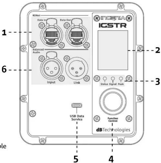
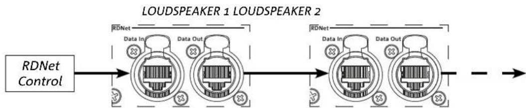
1. INPUT AND LINK OF RDNet NETWORK CONNECTION
Section compatible with network cables with RJ45 connectors. Especially:
- “Data In” is used to connect with the network signal from an RDNet Control or the Data Out port of another RDNet device
- "Data Out" is used to link the network to other devices in daisy-chain configuration
2. OLED DISPLAY
It displays and allows management of the loudspeaker parameters. See chapter CONTROL PANEL AND SETTING MENU.
3. LED STATUS
The LEDs show the loudspeaker status immediately, according to the logic summarised in the table below:
text_image
RDNet Data In Data Out Balanced Audio Input Link USB Data Service ICSTR Status Signal Peak Function Control dbTechnologies 1 2 3 4 5 6 ole| ICSTR | Status Signal Peak | ||
| Power-up | STEADY ON FOR A FEW SECONDS | OFF OFF | |
| Use OFF | SIGNAL OUTPUT STATUS | COMPRESSION LIMITER STATUS | |
| Partial failure CYCLIC | FLASHING ACTIVE OFF | ||
| Total failure ACTIVE | OFF CYCLIC FLASHING | ||
| RDNet connection FL | ASHING OFF OFF | ||
| Standby display OFF | CYCLIC FLASHING OFF |
4. PUSH ROTARY ENCODER
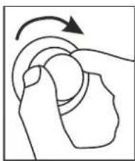
The push rotary encoder allows both rotary selection (selection of menus and values) and push selection (selection confirmation) to navigate the menus.
5. SERVICE DATA USB PORT
You can update the loudspeaker firmware using the USB Type C port. More details are available at http://www.dbtechnologies.com under "DOWNLOADS" and in section FIRMWARE UPDATES.
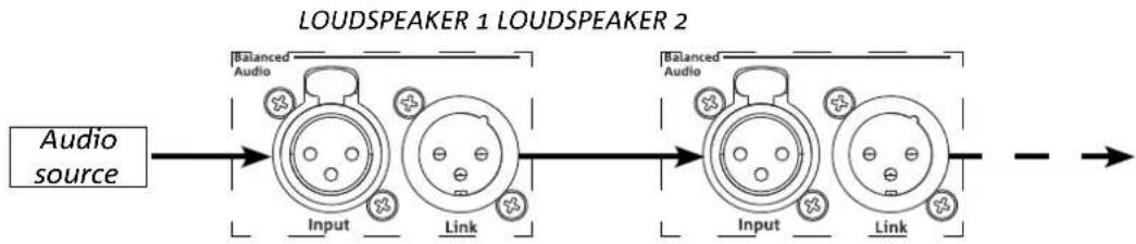
7. INPUT AND OUTPUT LINK ("Balanced audio")
Input and output compatible with balanced XLR cables. Especially:
- "Input" is used to connect the audio signal coming from an audio device;
- "Output Link" is used to link the signal to other loudspeakers in daisy-chain configuration.
IG5TR
Code 420120452 REV. 1.1
POWER SUPPLY UNIT SECTION
text_image
CAUTION RISK OF ELECTRICAL SHOCK DO NOT OPEN ATTENTION RISQUE DE CHCH ELECTRIQUE NE PAS OUvrir WARNING HOT SURFACE FULL RANGE MAINS INPUT 100-240V~ 50-60Hz 220-240V~ 50-60Hz 2,3A 100-120V~ 50-60Hz 4,6A MAINS LINK 220-240V~ (13,7Amax) 3150Wmax 100-120V~ (15,4Amax) 1690Wmax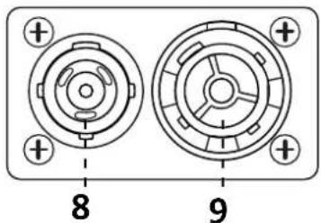
natural_image
Diagram of two circular mechanical components with labeled ports (no text or symbols beyond labels 8 and 9)8. "MAINS INPUT" POWER CONNECTOR
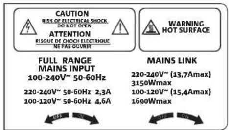
Compatible with powerCON TRUE1® connector. Full-range power supply.
9. "MAINS LINK" POWER DAISY CHAIN
Compatible with powerCON TRUE1® connector for power daisy chain to other modules. To know the maximum number of modules that can be connected in a daisy-chained system, refer to the “INSTALLATION” section of this manual.
2. FIRST POWER-UP
PACKAGE CONTENTS
Check that the package content of the INGENIA IG5TR loudspeaker is complete.
The package contains:
- power supply cable with Neutrik® powerCON TRUE1® connector
- IG5TR loudspeaker
- rain cover
- quick start user manual and warranty documents
IG5TR Code 420120452 REV. 1.1
INSTALLATION
AUDIO SIGNAL CONNECTION AND LINK
To link the audio signal, first connect the audio source coming from a mixer or another loudspeaker to the "INPUT" of the first loudspeaker. Then, connect the "LINK" output of the first loudspeaker to the "INPUT" of the second loudspeaker with a balanced XLR cable. Repeat this operation for all loudspeakers in the chain.
flowchart
graph LR
    A["Audio source"] --> B["Input"]
    B --> C["LOUDSPEAKER 1"]
    C --> D["Output"]
    B --> E["Link"]
    E --> F["LOUDSPEAKER 2"]
    F --> G["Output"]
POWER SUPPLY CONNECTION AND LINK
It is possible to link the power supply from one IG5TR loudspeaker to the next:
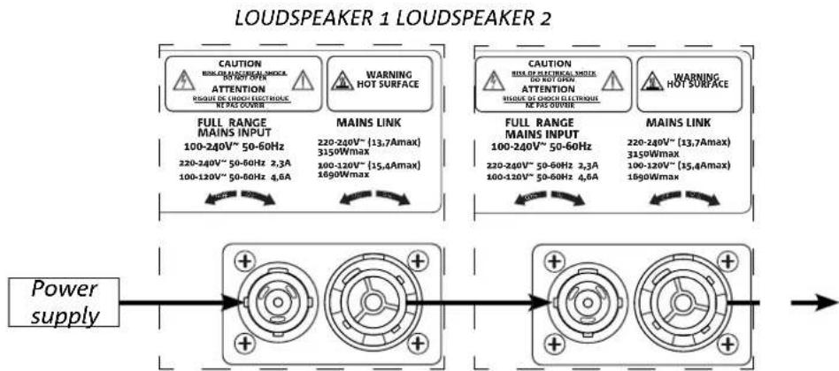
- up to a total of 6 (5+1) per power supply line in countries with 220-240 Vac power supply voltage and 4 (3+1) in countries with 100-120 Vac power supply voltage.
To provide power, simply connect the supplied power supply cable to the MAINS INPUT of the first loudspeaker, then connect a second cable with appropriate connectors (optional) from the MAINS LINK output to the MAINS INPUT of the next loudspeaker. Repeat the connection process until you reach the maximum allowed current indicated on the MAINS LINK connector of the first loudspeaker.
flowchart
graph LR
    A["CAUTION\nBIOLO DIRECTION INSUL\nOUT OF WM\nATTENTION\nRISQUE DE CHOICE ELECTROUS\nNE PAS OUTVER"] --> B["FULL RANGE MAINS INPUT\n100-240V~ 50-60Hz\n220-240V~ 50-60Hz 2,3A\n100-120V~ 50-60Hz 4,6A"]
    C["WARNING HOT SURFACE"] --> D["FULL RANGE MAINS INPUT\n100-240V~ 50-60Hz\n220-240V~ 50-60Hz 2,3A\n100-120V~ 50-60Hz 4,6A"]
    E["MAINS LINK"] --> F["FULL RANGE MAINS INPUT\n100-240V~ 50-60Hz\n220-240V~ 50-60Hz 2,3A\n100-120V~ 50-60Hz 4,6A"]
    G["CAUTION\nBIOLO DIRECTION INSUL\nOUT OF WM\nATTENTION\nRISQUE DE CHOICE ELECTROUS\nNE PAS OUTVER"] --> H["FULL RANGE MAINS INPUT\n100-240V~ 50-60Hz\n220-240V~ 50-60Hz 2,3A\n100-120V~ 50-60Hz 4,6A"]
    I["WARNING HOT SURFACE"] --> J["FULL RANGE MAINS INPUT\n100-240V~ 50-60Hz\n220-240V~ 50-60Hz 2,3A\n100-120V~ 50-60Hz 4,6A"]
    K["MAINS LINK"] --> L["FULL RANGE MAINS INPUT\n100-240V~ 50-60Hz\n220-240V~ 50-60Hz 2,3A\n100-120V~ 50-60Hz 4,6A"]
    M["Power supply"] --> N["Power Supply"]
    N --> O["+"]
    O --> P["+"]
    P --> Q["+"]
    Q --> R["+"]
    R --> S["+"]
    S --> T["+"]
    T --> U["+"]
    U --> V["+"]
    V --> W["+"]
    W --> X["+"]
    X --> Y["+"]
    Y --> Z["+"]
    Z --> AA["+"]
    AA --> AB["+"]
    AB --> AC["+"]
    AC --> AD["+"]
    AD --> AE["+"]
    AE --> AF["+"]
    AF --> AG["+"]
    AG --> AH["+"]
    AH --> AI["+"]
    AI --> AJ["+"]
    AJ --> AK["+"]
    AK --> AL["+"]
    AL --> AM["+"]
    AM --> AN["+"]
    AN --> AO["+"]
    AO --> AP["+"]
    AP --> AQ["+"]
    AQ --> AR["+"]
    AR --> AS["+"]
    AS --> AT["+"]
    AT --> AU["+"]
    AU --> AV["+"]
    AV --> AW["+"]
    AW --> AX["+"]
    AX --> AY["+"]
    AY --> AZ["+"]
    AZ --> BA["+"]
    BA --> BB["+"]
    BB --> BC["+"]
    BC --> BD["+"]
    BD --> BE["+"]
    BE --> BF["+"]
    BF --> BG["+"]
    BG --> BH["+"]
    BH --> BI["+"]
    BI --> BJ["+"]
    BJ --> BK["+"]
    BK --> BL["+"]
    BL --> BM["+"]
    BM --> BN["+"]
    BN --> BO["+"]
    BO --> BP["+"]
    BP --> BQ["+"]
    BQ --> BR["+"]
    BR --> BS["+"]
    BS --> BT["+"]
    BT --> BU["+"]
    BU --> BV["+"]
    BV --> BW["+"]
    BW --> BX["+"]
    BX --> BY["+"]
    BY --> BZ["+"]
    BZ --> CA["+"]
    CA --> CB["+"]
    CB --> CC["+"]
    CC --> CD["+"]
    CD --> CE["+"]
    CE --> CF["+"]
    CF --> CG["+"]
    CG --> CH["+"]
    CH --> CI["+"]
    CI --> CJ["+"]
    CJ --> CK["+"]
    CK --> CR["+"]
    CR --> CS["+"]
    CS --> CT["+"]
    CT --> CU["+"]
    CU --> CV["+"]
    CV --> CW["+"]
    CW --> CX["+"]
    CX --> CY["+"]
    CY --> CZ["+"]
    CZ --> DA["+"]
    DA --> DB["+"]
    DB --> DC["+"]
    DC --> DD["+"]
    DD --> DJ["+"]
    DJ --> DK["+"]
RDNET SIGNAL CONNECTION AND LINK
For remote control, connect the Data Input of the first loudspeaker to the hardware controller (RDNet Control) with CAT5 or higher category cables equipped with etherCON connectors. Then connect the Data Output of the first loudspeaker to the Data Input of the second loudspeaker and so on.
flowchart
graph LR
    A["RDNet Control"] --> B["LOUDSPEAKER 1"]
    B --> C["LOUDSPEAKER 2"]
    C --> D["Output"]
IG5TR
Code 420120452 REV. 1.1
3. REMOTE CONTROL
Use the AURORA NET software to manage various parameters of the IG5TR loudspeakers in real-time. In detail:
• Monitor the input and output signal
• View any presence of audio compression in the output signal
• Attenuate the input signal
- Put the individual amplification channels in MUTE
• Monitor the amplifier temperature
- Save settings in presets and recall them
• Equalise the speaker
- Add delay
- Set the digital steering
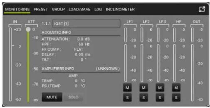
text_image
MONITORING PRESET GROUP LOAD/SAVE LOG INCLINOMETER IN ATT 1.1.1 IGST(1) +20 0 -10 -0 -30 -20 -50 -40 -70 -60 -∞ LF1 LF2 LF3 HF OUT ADQUOSTIC INFO ATTENUATION: 0.0 dB HPF: 60 Hz HF COMP: FLAT DELAY: 0.00 ms TILT: 0 ° AMPLIFIERS INFO (UNKNOWN) AMP TEMP 0 °C PSU TEMP 0 °C M M M M MUTE SOLO S S S S -20 -20 -20 -20 -20 -20 -20 -20 -20 -20 -40 -40 -40 -40 -∞ -∞ -∞ -∞ M M M M S S S S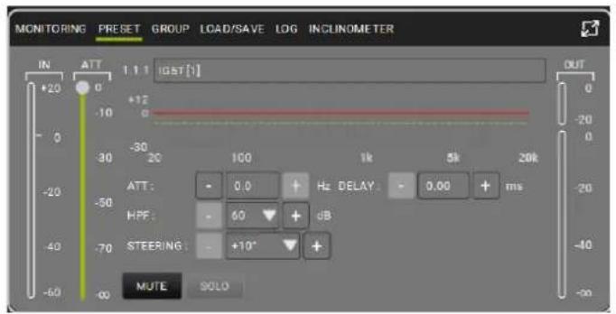
text_image
MONITORING PRESET GROUP LOAD/SAVE LOG INCLINOMETER IN ATT 1.1.1 iGST[1] +20 0 -10 -30 20 100 1k 5k 20k ATT: 0.0 Hz DELAY: 0.00 ms HPF: 60 dB STEERING: +10° + MUTE SOLO OUT 0 -20 0 -20 -40 -90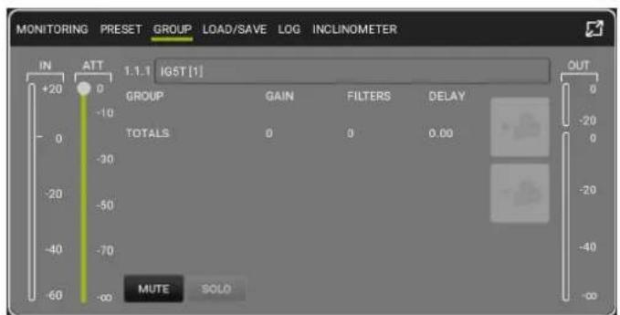
text_image
MONITORING PRESET GROUP LOAD/SAVE LOG INCLINOMETER IN ATT 1.1.1 IGST [1] +20 0 GROUP GAIN FILTERS DELAY -10 0 TOTALS 0 0 0.00 -30 -20 -50 -40 -70 -60 MUTE SOLO OUT 0 -20 0 -20 -40 -60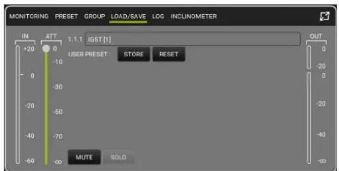
text_image
MONITORING PRESET GROUP LOAD/SAVE LOG INCLINOMETER IN ATT 1.1.1 IGST [1] +20 0 -10 -30 -50 -70 -90 -60 OUT USER PRESET: STORE RESET MUTE SOLO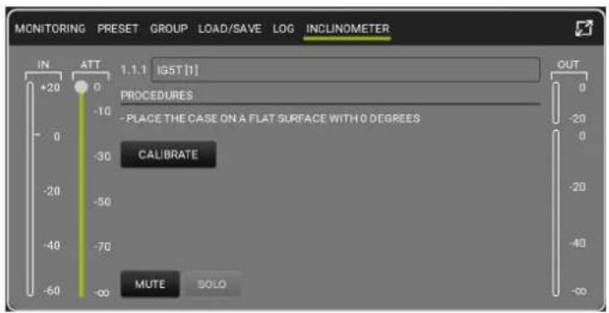
text_image
MONITORING PRESET GROUP LOAD/SAVE LOG INCLINOMETER IN ATT 1.1.1 IGST [1] +20 0 PROCEDURES -10 -20 0 -30 CALIBRATE -20 -40 -40 -60 MUTE SOLO OUT 0 -20 0 -20 -40 -60IG5TR Code 420120452 REV. 1.1
4. CONTROL PANEL AND SETTING MENU
ACCESSING THE MENUS
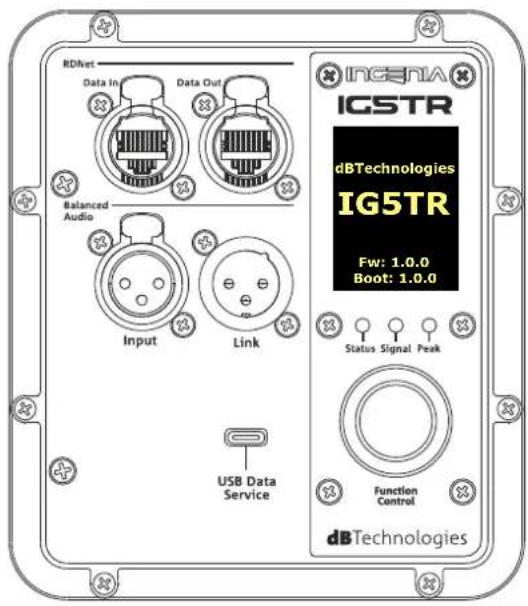
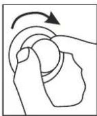
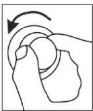
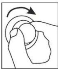
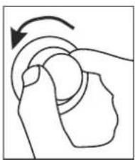
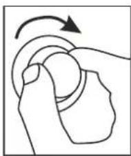
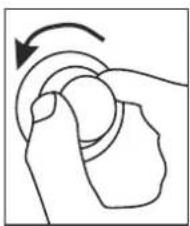
The push rotary encoder allows both selection by turning it and confirmation by pressing it. These selections and confirmations allow navigation through the menus, visible on the OLED display. Within the menus, rotation to the right or left also allows an increase or decrease of the selected values.
text_image
RDNet Data In Data Out Balanced Audio Input Link USB Data Service INGNIA IGSTR dBTechnologies IG5TR Fw: 1.0.0 Boot: 1.0.0 Status Signal Peak Function Control dBTechnologies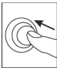
natural_image
Hand pressing a button on a circular button with an arrow indicating rotation (no text or symbols)
natural_image
Simple line drawing of a hand pressing a button with an arrow indicating rotation (no text or symbols)
natural_image
Simple line drawing of a hand pressing a button with an arrow indicating rotation (no text or symbols)
Examples of using the push rotary encoder

- Once manual settings have been made, they are stored even after the speaker has been switched off.
- After about a minute of no selections or confirmations, the system returns to the home screen. You can return to the home screen intentionally from any point also by pressing and holding the push rotary encoder for a few seconds.
IG5TR
Code 420120452 REV. 1.1
MAIN PAGE
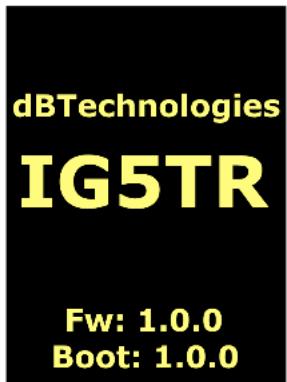
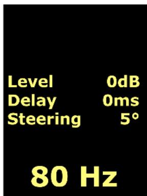
Upon power-up, the display shows the loudspeaker model and the installed firmware and bootloader versions. After a few seconds, the Main Page is displayed, showing the main parameters of the loudspeaker. In the event of a malfunction, the Main Page alternates flashing with the warning message.
text_image
dBTechnologies IG5TR Fw: 1.0.0 Boot: 1.0.0Startup
text_image
Level 0dB Delay 0ms Steering 5° 80 HzMain Page Offline Mode
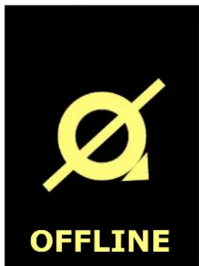
Once connected to the AURORA Net software (via "Go Online" software option), the display shows the successful connection, and once disconnected, it returns to offline mode. In the event of a malfunction, the Main Page alternates flashing with the warning message.

text_image
Q ONLINEMain Page Go Online
text_image
OFFLINEMain Page Go Offline
PRESET MENU
The preset menu features 5 memory locations for five different loudspeaker settings. The Factory location is dedicated to the factory preset; the user is free to modify the loudspeaker settings from the display and save any changes in one of the available memory locations (1, 2, 3).
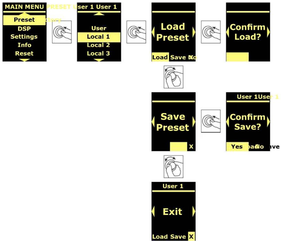
flowchart
graph TD
    A["MAIN MENU"] --> B["Preset DSP Settings Info Reset"]
    B --> C["User 1 User 1"]
    C --> D["User Local 1 Local 2 Local 3"]
    D --> E["Load Preset"]
    E --> F["Load Save No"]
    F --> G["Confirm Load?"]
    G --> H["Save Preset"]
    H --> I["User 1 User 1"]
    I --> J["Confirm Save?"]
    J --> K["Yes no Save"]
    K --> L["User 1"]
    L --> M["Exit Load Save X"]
The “User” memory location is used to store a UserEQ from the AURORA Net software (see image below). The Store button stores the UserEQ and the preset in “Aurora” memory location, which can be recalled on the loudspeaker by the user when the loudspeaker is offline.
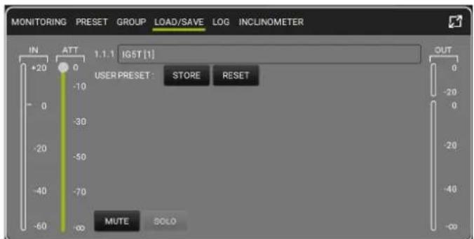
text_image
MONITORING PRESET GROUP LOAD/SAVE LOG INCLINOMETER IN ATT 1.1.1 IGST [1] +20 0 -10 USER PRESET: STORE RESET -30 -50 -70 -60 MUTE SOLO OUT 0 -20 0 -20 -40 -60IG5TR
Code 420120452 REV. 1.1
DSP MENU
The DSP menu allows you to set IG5TR loudspeaker parameters, including:
- gain
- delay
• cut-off frequency of high-pass filter - digital steering
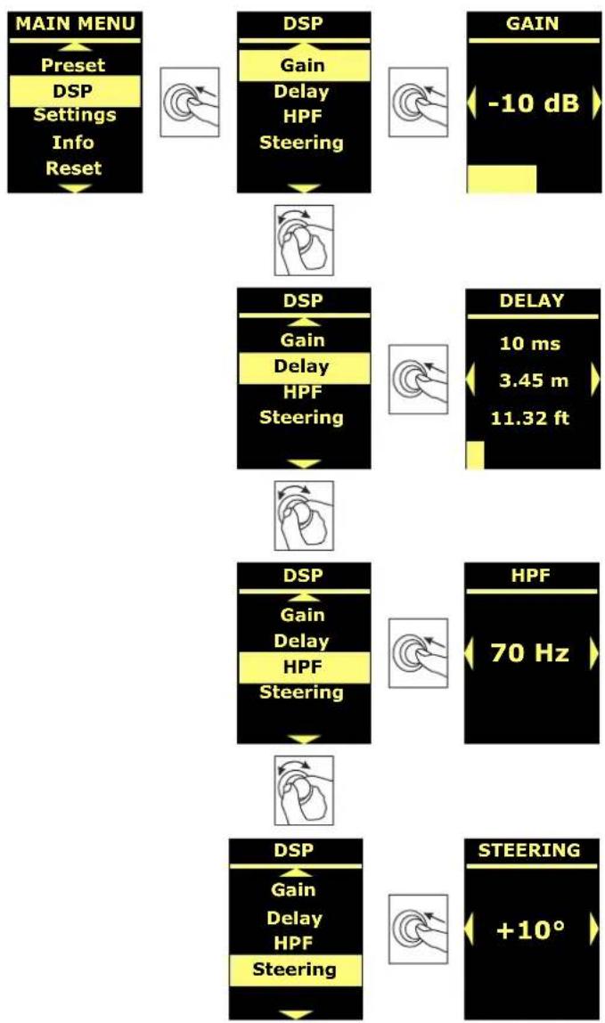
flowchart
graph TD
    A["MAIN MENU"] --> B["Preset DSP Settings Info Reset"]
    B --> C["DSP Gain Delay HPF Steering"]
    C --> D["GAIN -10 dB"]
    D --> E["DSP Gain Delay HPF Steering"]
    E --> F["DELAY 10 ms 3.45 m 11.32 ft"]
    F --> G["DSP Gain Delay HPF Steering"]
    G --> H["HPF 70 Hz"]
    H --> I["DSP Gain Delay HPF Steering"]
    I --> J["STEERING +10°"]
SETTING MENU
From this menu, you can set the Master and Slave assignment mode (when two loudspeakers are coupled), activate the display standby mode and change its brightness.
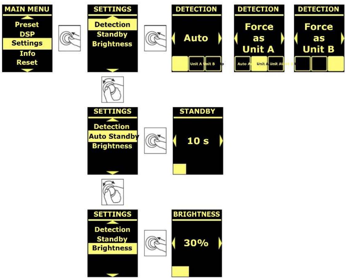
flowchart
graph TD
    A["MAIN MENU"] --> B["Preset DSP"]
    B --> C["Settings Info Reset"]
    C --> D["SETTINGS Detection Standby Brightness"]
    D --> E["DETECTION Auto"]
    E --> F["Force as Unit A"]
    F --> G["DETECTION Force as Unit B"]
    G --> H["SETTINGS Detection Auto Standby Brightness"]
    H --> I["STANDBY 10 s"]
    I --> J["SETTINGS Detection Standby Brightness"]
    J --> K["BRIGHTNESS 30%"]
IG5TR
Code 420120452 REV. 1.1
INFO MENU
The Info menu displays in real-time the amplifier and DSP temperature, the loudspeaker model, and the firmware and bootloader versions currently installed on the loudspeaker.
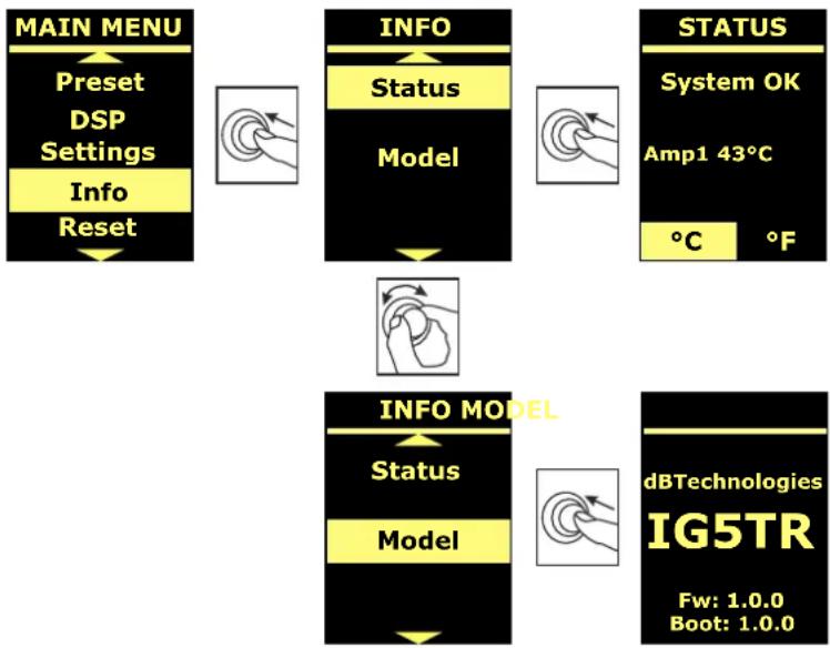
flowchart
graph TD
    A["MAIN MENU"] --> B["Preset DSP Settings"]
    B --> C["Info Reset"]
    D["INFO"] --> E["Status"]
    E --> F["Model"]
    G["STATUS"] --> H["System OK"]
    H --> I["Amp1 43°C"]
    I --> J["°C °F"]
    K["INFO MODEL"] --> L["Status"]
    L --> M["Model"]
    N["dBTechologies IG5TR"] --> O["Fw: 1.0.0\nBoot: 1.0.0"]
RESET MENU
The Reset menu allows you to delete the user presets only, or restore the factory settings.
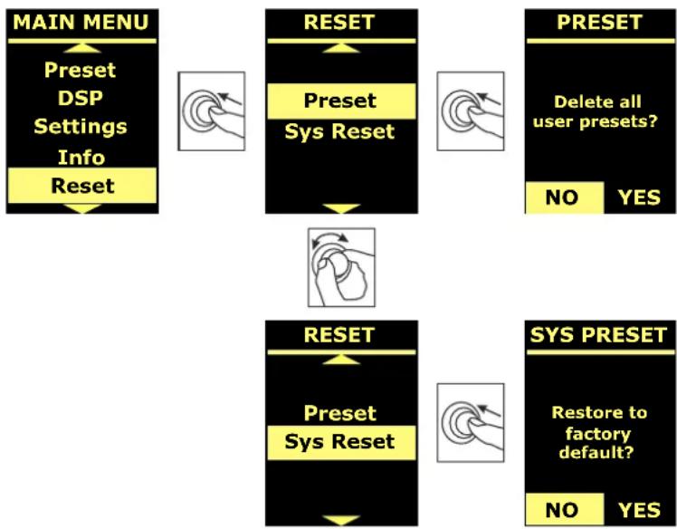
flowchart
graph TD
    A["MAIN MENU"] --> B["Preset DSP Settings Info Reset"]
    B --> C["RESET"]
    C --> D["Preset Sys Reset"]
    D --> E["RESET"]
    E --> F["Preset Sys Reset"]
    F --> G["SYS PRESET"]
    G --> H["Restore to factory default?"]
    H --> I["NO YES"]
    style A fill:#f9f,stroke:#333
    style B fill:#ccf,stroke:#333
    style C fill:#cfc,stroke:#333
    style D fill:#fcc,stroke:#333
    style E fill:#cff,stroke:#333
    style F fill:#ffc,stroke:#333
    style G fill:#cfc,stroke:#333
    style H fill:#fcc,stroke:#333
    style I fill:#ffc,stroke:#333
5. INSTALLATION EXAMPLES
This section features installation examples. For further information, please refer to the accessory instructions and the requirements indicated on any product labels.
WARNING!

The product and accessories must be handled by experienced personnel only! Make sure that the installation is positioned in a stable and safe manner in order to avoid hazardous conditions for people, animals and/or objects.
The user is required to follow regulations and mandatory laws on safety of the country in which the product is used. For safe use, regularly check the operation of all parts and integrity before use. Design, calculations, installation, testing and maintenance of suspended systems or professional audio stacks must be performed by authorized personnel only. AEB Industriale is not responsible for improper installations, non-compliant with safety requirements.
WARNING!

The use of handles for improper purposes, such as hanging, is prohibited. Standing on the loudspeaker itself is also strictly forbidden.
Ensure installation is carried out on a flat surface. If this is not possible, take special additional securing measures to prevent any risk of falling or tipping over.
The IG5TR loudspeaker must only be installed vertically.
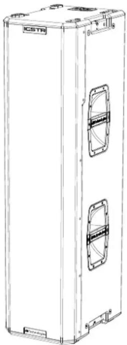
natural_image
Line drawing of a rectangular industrial enclosure with internal compartments and mounting brackets (no text or symbols)IG5TR
Code 420120452 REV. 1.1
STACKED INSTALLATION
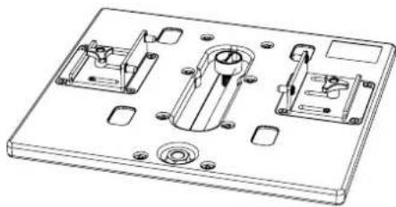
Using the GSA-IG5TR accessory (not included), it is possible to use IG5TR loudspeakers (1 or 2) mounted on the ground or on subwoofers (featuring an M20 pole mount). In this way, an extremely compact and powerful system can be obtained over all acoustic frequencies with ground installation.
When installing two loudspeakers stacked using the LP-1 brackets included, with the upper one mounted upside down, an additional mechanical fastening or a belt fastening is required to correctly fix the installation. Refer to the accessory user manual.
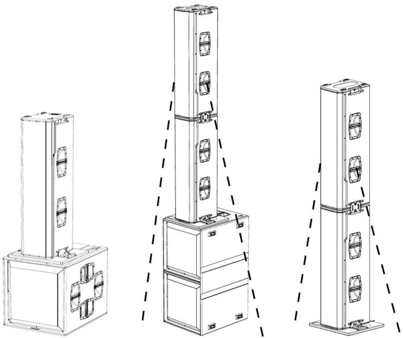
natural_image
Technical line drawings of three vertical industrial equipment units with mounting brackets and ventilation slots (no text or symbols)IG5TR Code 420120452 REV. 1.1
FLOWN INSTALLATION
Using the DRK-IG5TR accessory, up to two loudspeakers can be suspended with variable inclination depending on the suspension point used; the upper loudspeaker must always be mounted upside down to maintain consistent sound reinforcement.
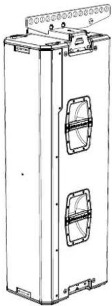
natural_image
Technical line drawing of a vertical rectangular device with two internal compartments and mounting brackets (no text or symbols)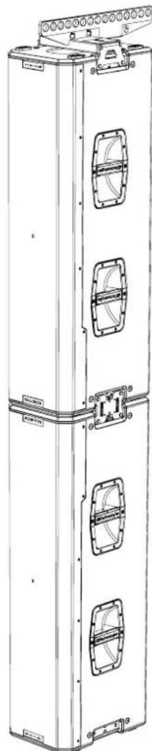
natural_image
Technical line drawing of a vertical industrial cabinet with multiple compartments and mounting brackets (no text or symbols)IG5TR
Code 420120452 REV. 1.1
DIGITAL STEERING
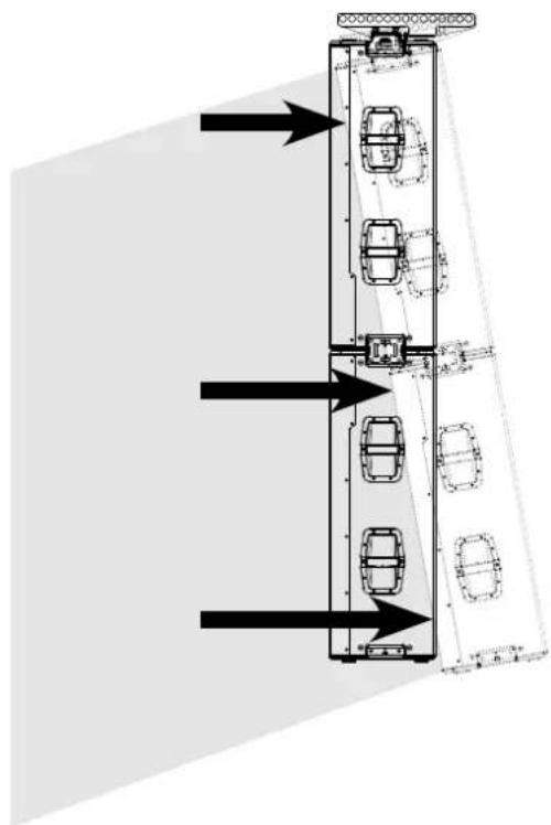
Digital steering is a technology that can be suitably adopted to direct the sound coverage of a loudspeaker or of two stacked loudspeakers, changing it according to the requirements of the settings of use and installation. The IG5TR loudspeaker DSP renders the acoustic wavefront of 2 stacked speakers as that of a single angled speaker, as shown in the figure.
natural_image
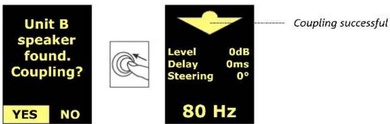
Diagram of a multi-level vehicle assembly with directional arrows indicating flow or movement (no text or symbols)During setup, once the two loudspeakers are stacked (with the upper one upside down) and switched on, the infrared ports on the upper side of both send a message via the display that the coupling process can be started.
text_image
Unit B speaker found. Coupling? YES NO 80 Hz Level 0dB Delay 0ms Steering 0° Coupling successfulOnce the coupling sequence is complete, all loudspeaker parameters return to factory settings; the acoustic coverage can be modified from the display on the Steering page (see DSP MENU).
IG5TR Code 420120452 REV. 1.1
6. TROUBLESHOOTING
The loudspeaker will not turn on:
- Check that power supply is present upstream of the installation.
- Check that the power supply or the link connection of the power supply is properly inserted and locked (clockwise movement).
The speaker turns on but produces no sound:
- Check that the audio signal input connections or the audio signal re-links are properly carried out.
- Check that the audio source (mixer) is properly connected and active.
- In case of RDNet network connection and control with AURORA NET, check that the MUTE function is disabled.
- Restore to factory default to reset the EQ and any other parameters.
The loudspeaker sound is not fully satisfactory.
- Check that, in case of RDNet network connection and control with AURORA NET, all the parameters are properly set.
7. FIRMWARE UPDATES
It is very important to keep the product firmware updated to the latest version to ensure full performance. Please check the site http://www.dbtechnologies.com periodically for updates under section "DOWNLOADS".
- Download and install on your PC the USB BURNER MANAGER under the "SOFTWARE & CONTROLLER" section.
- Download the .zip file of the latest firmware in the "DOWNLOADS" section of your product.
- Connect the product to the PC using a USB cable (not provided) with a suitable connector type (see this

detail in the "FEATURES OF THE AMPLIFICATION AND CONTROL SECTION" chapter)
- In the top right corner of the USB BURNER MANAGER screen, select "File Opening".
- Select the file containing the previously downloaded firmware.
- Follow the operations shown on the screen.
- Click "UPDATE".
You can update the product firmware also via AURORA NET software, in the "Firmware Update" section.

WARNING!
Before proceeding with the USB update, make sure the speaker has been switched off for at least 10 minutes.
IG5TR
Code 420120452 REV. 1.1
8. SPECIFICATIONS
GENERAL INFORMATION
| Type: | 2-way active speaker |
ACOUSTICAL SPECIFICATIONS
| Frequency response [- 6 dB]: 57 - 16500 Hz | |
| Frequency response [- 10 dB]: 55 - 20000 Hz | |
| Max SPL (1 m): | 138 dB AES75 *135.5 dB ** |
| LF: 3 x 10” neo | |
| LF Voice Coil: 2.5” | |
| HF: 1.4” (exit) neo | |
| HF Voice Coil: 3” | |
| Coverage HxV 90° x 75° (+20°/-55°) | |
AMPLIFIER
| Amplification class: Class D | |
| Amplification power (Peak) 3200 W | |
| Amplification power (RMS): 4x 400W (1600 W tot) | |
| Power supply: Full-range SMPS | |
| Cooling technique: Passive convection | |
| Operating temperature range (ambient): | from -20° to + +50° [°C] |
PROCESSOR
| Internal controller: | DSP 32 bit 96 kHz |
| Limiter: | Peak, RMS, Thermal |
* @1 meter, free field, AES75 with Music-Noise
** @1 meter, free field, SPL Max Peak with Pink Noise (CF=4)
IG5TR Code 420120452 REV. 1.1
USER INTERFACE
| Indicator LEDs: Status, Signal, Limiter | |
| Controls Push rotary encoder + OLED display | |
INPUTS AND OUTPUTS
| Power supply inputs and re-links: PowerCON® TRUE1 In/Link |
| Audio inputs/outputs: Balanced XLR In/Link Out |
| RDNet inputs/outputs: Data In / Data Out (etherCON® connectors) |
| USB (firmware update): 1x USB type C |
POWER SUPPLY SPECIFICATIONS (ABSORPTION)
| Absorption at 1/8th of power in average use conditions (*): | 1 A (220-240 V~)1.9 A (100-120 V~) |
| Absorption at 1/3rd of power in maximum use conditions (**): | 2.2 A (220-240V~)4.4 (100-120V~) |
| Absorption with speaker on in no-signal condition (idle): | 0.22 A (220-240 V~)0.47 A (100-120 V~) |
| Max. number of modules per power supply line[mains input + mains link]: | 5+1 (220-240 V~)3+1 (100-120 V~) |
* NOTE FOR INSTALLER: Values refer to 1/8th of power, under average operating conditions (music programme with occasional or no clipping). For any type of configuration we recommend to consider them as minimum sizing values.
** NOTE FOR INSTALLER: Values refer to 1/3rd of power, under heavy operating conditions (music programme with frequent clipping and limiter activation). In case of professional installations and tours we recommend sizing according to these values.
IG5TR
Code 420120452 REV. 1.1
DIMENSIONS
| Material: plywood cabinet - black polyurea finish | |
| Grille: Metal - CNC machining | |
| Handles: 4 (2x side) | |
| Accessory mounting points: 4 (2x top, 2x bottom) | |
| Width: 280 mm (11.02 in.) | |
| Height: 1100 mm (43.31 in.) | |
| Depth: 380 mm (14.96 in.) | |
| Weight: 35 kg (77.16 lbs) |
Product features, specifications and appearance are subject to changes without prior notice. dBTechnologies reserves the right to make changes or improvements in design or manufacture without any obligation to incorporate such changes or improvements in previously manufactured products.

natural_image
Abstract black-and-white geometric logo design with stylized letter-like shapes (no text or symbols)AEB INDUSTRIALE srl
A.E.B. Industriale Srl
Via Brodolini, 8
text_image
20° -55° 75° 90° Microscopetext_image
Technical diagram of an electronic device showing internal components with labeled parts C and D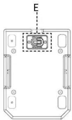
text_image
EZUBEHÖR
natural_image
Technical line drawing of a mechanical bracket assembly (no text or symbols)natural_image
Technical line drawing of a mechanical housing with internal components (no text or symbols)GSA-IG5TR Montageadapter
IG5TR
natural_image
Diagram of two circular mechanical components with labeled ports (no text or symbols beyond labels 8 and 9)natural_image
Hand pressing a button on concentric circles with an arrow indicating rotation (no text or symbols)
natural_image
Simple line drawing of a hand pressing a button with an arrow indicating rotation (no text or symbols)
natural_image
Hand holding a circular object with an arrow indicating rotation (no text or symbols)Main Page Offline Mode
Main Page Go Offline
MENÜ PRESET
flowchart
graph TD
    A["MAIN MENU"] --> B["Preset"]
    B --> C["DSP Settings Info Reset"]
    C --> D["DSP Gain Delay HPF Steering"]
    D --> E["GAIN -10 dB"]
    E --> F["DSP Gain Delay HPF Steering"]
    F --> G["DELAY 10 ms 3.45 m 11.32 ft"]
    G --> H["DSP Gain Delay HPF Steering"]
    H --> I["HPF 70 Hz"]
    I --> J["DSP Gain Delay HPF Steering"]
    J --> K["STEERING +10°"]
MENÜ SETTINGS
flowchart
graph TD
    A["MAIN MENU"] --> B["Preset DSP"]
    B --> C["Settings Info Reset"]
    C --> D["SETTINGS Detection Standby Brightness"]
    D --> E["DETECTION Auto"]
    E --> F["DETECTION Force as Unit A"]
    F --> G["DETECTION Force as Unit B"]
    G --> H["SETTINGS Detection Auto Standby Brightness"]
    H --> I["STANDBY 10 s"]
    I --> J["SETTINGS Detection Standby Brightness"]
    J --> K["BRIGHTNESS 30%"]
IG5TR
natural_image
Technical line drawing of a rectangular industrial enclosure with mounting flanges and internal compartments (no text or symbols)IG5TR
natural_image
Technical line drawings of three vertical industrial equipment units with mounting brackets and ventilation slots (no text or symbols)natural_image
Technical line drawing of a vertical rectangular device with two internal compartments and mounting brackets (no text or symbols)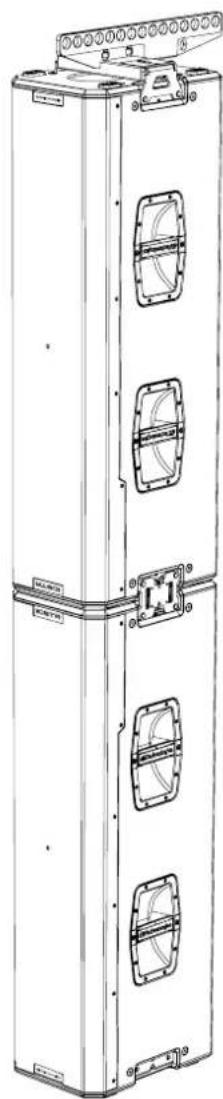
natural_image
Technical line drawing of a multi-tiered industrial or electrical cabinet with mounting brackets and mounting holes (no text or symbols)IG5TR
natural_image
Diagram of a multi-level vehicle parking or traffic structure with directional arrows indicating flow or movement (no text or symbols present)* @1 meter, free field, AES75 with Music-Noise
** @1 meter, free field, SPL Max Peak with Pink Noise (CF=4)
natural_image
Abstract black-and-white geometric logo design with stylized shapes (no text or symbols)AEB INDUSTRIALE srl
A.E.B. Industriale Srl
Via Brodolini, 8
INSTALLATION EN APPUI....93
INSTALLATION SUSPENDUE 94
LE DIGITAL STEERING 95
6. DÉPANNAGE....96
7. MISE À JOUR DU MICROLOGICIEL ......96
8. SPÉCIFICATIONS TECHNIQUES......97
INFORMATIONS GÉNÉRALES....97
DONNÉES ACOUSTIQUES....97
AMPLIFICATEUR....97
PROCESSEUR....97
INTERFACE UTILISATEUR 98
ENTRÉES ET SORTIES....98
SPÉCIFICATIONS D'ALIMENTATION (ABSORPTION) 98
DIMENSIONS....99
1. INFORMATIONS GÉNÉRALES
BIENVENUE !
text_image
20° -55° 75° 90° A:TechniqueIG5TR Code 420120452 RÉV. 1.1
MÉCANIQUE
text_image
Technical diagram of an electronic device showing internal components with labeled parts C and D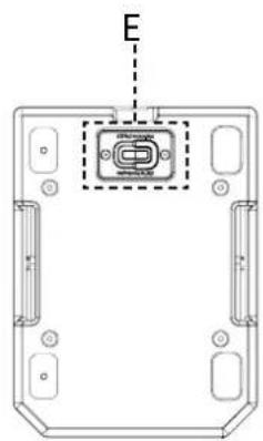
text_image
EACCESSOIRES
natural_image
Technical line drawing of a mechanical bracket assembly (no text or symbols)DRK-IG5TR
flybar
natural_image
Technical line drawing of a mechanical housing with internal components and mounting holes (no text or symbols)text_image
RDNet Data In Data Out Balanced Audio Input Link USB Data Service ICSTR Status Signal Peak Function Control dB Technologies 1 2 3 4 5| ICSTR | Status Signal Peak | ||
| Allumage | ALLUMÉ FIXE PENDANT QUELQUES SECONDES | ÉTEINT ÉTEINT | |
| Utilisation ÉTEINT | SIGNAL OUTPUT STATUS | COMPRESSION LIMITER STATUS | |
| Anomalie partielle | CLIGNOTEMENT CYCLIQUE | ACTIF ÉTEINT | |
| Anomalie totale ACTIF ÉTEINT | CLIGNOTEMENT CYCLIQUE | ||
| Connexion RDNet CLIGNOTEMENT ÉTEINT ÉTEINT | |||
| Écran en mode veille | ÉTEINT | CLIGNOTEMENT CYCLIQUE | ÉTEINT |
4. ENCODEUR À PRESSION ROTATIF
natural_image
Two circular mechanical or electrical component diagrams labeled 8 and 9, with no visible text or symbols beyond labels.text_image
RDNet Data In Data Out Balanced Audio Input Link USB Data Service IGSTR dBTechnologies IG5TR Fw: 1.0.0 Boot: 1.0.0 Status Signal Peak Function Control dBTechnologies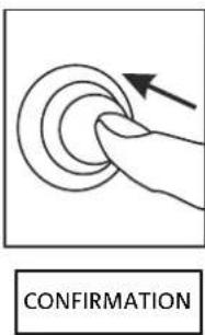
text_image
CONFIRMATION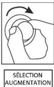
text_image
SÉLECTION AUGMENTATION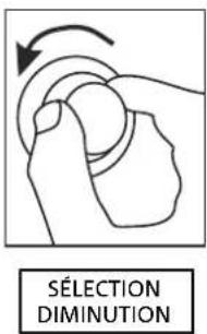
text_image
SÉLECTION DIMINUTIONMain Page Offline Mode
Main Page Go Offline
MENU PRESET
flowchart
graph TD
    A["MAIN MENU"] --> B["Preset DSP Settings Info Reset"]
    B --> C["DSP Gain Delay HPF Steering"]
    C --> D["GAIN -10 dB"]
    D --> E["DSP Gain Delay HPF Steering"]
    E --> F["DELAY 10 ms 3.45 m 11.32 ft"]
    F --> G["DSP Gain Delay HPF Steering"]
    G --> H["HPF 70 Hz"]
    H --> I["DSP Gain Delay HPF Steering"]
    I --> J["STEERING +10°"]
MENU SETTINGS
flowchart
graph TD
    A["MAIN MENU"] --> B["Preset DSP"]
    B --> C["Settings Info Reset"]
    C --> D["SETTINGS Detection Standby Brightness"]
    D --> E["DETECTION Auto"]
    E --> F["Force as Unit A"]
    F --> G["DETECTION Force as Unit B"]
    G --> H["SETTINGS Detection Auto Standby Brightness"]
    H --> I["STANDBY 10 s"]
    I --> J["SETTINGS Detection Standby Brightness"]
    J --> K["BRIGHTNESS 30%"]
IG5TR
Code 420120452 RÉV. 1.1
MENU INFO
natural_image
Technical line drawing of a rectangular industrial enclosure with mounting flanges and internal compartments (no text or symbols)IG5TR
Code 420120452 RÉV. 1.1
INSTALLATION EN APPUI
natural_image
Technical line drawings of three vertical industrial equipment units with mounting brackets and ventilation slots (no text or symbols)IG5TR Code 420120452 RÉV. 1.1
INSTALLATION SUSPENDUE
natural_image
Diagram of a multi-level vehicle parking or traffic structure with directional arrows indicating flow or movement (no text or symbols present)* @1 meter, free field, AES75 with Music-Noise
** @1 meter, free field, SPL Max Peak with Pink Noise (CF=4)
IG5TR Code 420120452 RÉV. 1.1
INTERFACE UTILISATEUR
SPÉCIFICATIONS D'ALIMENTATION (ABSORPTION)
natural_image
Abstract black-and-white geometric logo design with stylized shapes (no text or symbols)AEB INDUSTRIALE srl
A.E.B. Industriale Srl
Via Brodolini, 8
text_image
20° -55° 75° 90° MicroscopeIG5TR Cód. 420120452 REV. 1.1
MECÁNICA
natural_image
Technical line drawing of a mechanical bracket assembly (no text or symbols)DRK-IG5TR
flybar
natural_image
Technical line drawing of a mechanical housing with internal components (no text or symbols)text_image
RDNet Data In Data Out Balanced Audio Input Link USB Data Service ICSTR Status Signal Peak Function Control dB Technologies la 1 2 3 4 5natural_image
Diagram of two circular electrical connector terminals labeled 8 and 9, with no text or symbols beyond labelsnatural_image
Hand pressing a button on a circular button with an arrow indicating rotation (no text or symbols)
natural_image
Simple line drawing of a hand pressing a button with an arrow indicating rotation (no text or symbols)
natural_image
Simple line drawing of a hand pressing a button with an arrow indicating rotation (no text or symbols)flowchart
graph TD
    A["MAIN MENU"] --> B["Preset DSP Settings Info Reset"]
    B --> C["DSP Gain Delay HPF Steering"]
    C --> D["GAIN -10 dB"]
    D --> E["DSP Gain Delay HPF Steering"]
    E --> F["DELAY 10 ms 3.45 m 11.32 ft"]
    F --> G["DSP Gain Delay HPF Steering"]
    G --> H["HPF 70 Hz"]
    H --> I["DSP Gain Delay HPF Steering"]
    I --> J["STEERING +10°"]
MENÚ SETTINGS
flowchart
graph TD
    A["MAIN MENU"] --> B["Preset DSP"]
    B --> C["Settings Info Reset"]
    C --> D["SETTINGS Detection Standby Brightness"]
    D --> E["DETECTION Auto"]
    E --> F["Force as Unit A"]
    F --> G["DETECTION Force as Unit B"]
    G --> H["SETTINGS Detection Auto Standby Brightness"]
    H --> I["STANDBY 10 s"]
    I --> J["SETTINGS Detection Standby Brightness"]
    J --> K["BRIGHTNESS 30%"]
MENÚ INFO
natural_image
Technical line drawing of a rectangular industrial enclosure with internal compartments and mounting brackets (no text or symbols)IG5TR
Cód. 420120452 REV. 1.1
natural_image
Technical line drawings of three vertical industrial equipment units with mounting brackets and ventilation slots (no text or symbols)IG5TR Cód. 420120452 REV. 1.1
INSTALACIÓN COLGADA
natural_image
Technical line drawing of a rectangular industrial or electronic device with two internal compartments and mounting brackets (no text or symbols)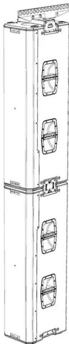
natural_image
Technical line drawing of a multi-tiered vertical industrial or mechanical cabinet with mounting flanges and internal compartments (no text or symbols)IG5TR
Cód. 420120452 REV. 1.1
EL DIGITAL STEERING
natural_image
Diagram of a multi-level vehicle parking structure with directional arrows indicating flow or movement (no text or labels)* @1 meter, free field, AES75 with Music-Noise
** @1 meter, free field, SPL Max Peak with Pink Noise (CF=4)
IG5TR Cód. 420120452 REV. 1.1
INTERFAZ USUARIO
| Indicadores led: Status, Signal, Limiter | |
| Controles Codificador rotatorio + pantalla OLED | |
ENTRADAS Y SALIDAS
natural_image
Abstract black-and-white graphic design with stylized letters (no text or symbols)AEB INDUSTRIALE srl
A.E.B. Industriale Srl
Via Brodolini, 8