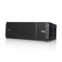
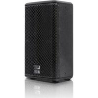
VIO L212 - Loudspeaker DB Technologies - Free user manual and instructions
Find the device manual for free VIO L212 DB Technologies in PDF.


| Product type | Active 3-way line-array module |
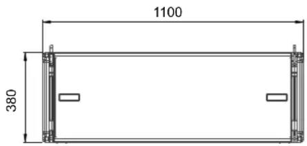
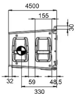
| Dimensions (W x H x D) | 1100 x 380 x 450 mm |
| Weight | 54.4 kg |
| Power supply | Fullrange with PFC, 100-240 V~ (50-60 Hz) |
| Power consumption (idle) | 53 W |
| Power consumption (1/8 power) | 2 A (230 V~) / 3.1 A (115 V~) |
| Frequency response (-10 dB) | 49.8 Hz - 20 kHz |
| Maximum SPL | 142 dB (depending on frequency and preset) |
| Amplifier | 2 x Digipro G4, Class D, 2 x 1600 W RMS (3200 W peak), total 6400 W RMS |
| HF transducers | 2 x 1.4" compression driver, 3" titanium coil |
| MF transducers | 4 x 6.5" neodymium, 2" coil |
| LF transducers | 2 x 12" neodymium, 3" coil |
| Horizontal directivity | 90° |
| DSP processor | 32-bit, FIR filtering, 24 bit / 96 kHz conversion |
| Audio input/output connectors | 1 x XLR IN balanced (Floating ADC), 1 x XLR LINK OUT |
| Network connectors | Data In / Data Out (etherCON RJ45) for RDNet |
| USB port | 1 x USB mini B (for firmware update) |
| Power connectors | PowerCON TRUE1 IN / LINK |
| Rigging system | 3-point front/rear attachment with brackets and pins, adjustable angles from 0° to 8° |
| Cabinet material | Wood, black polyurea finish |
| Operating temperature | -15 °C to +55 °C |
| Control software | AURORA NET, dBTechnologies COMPOSER, EASE Focus 3 |
| Compatible accessories | Fly-bar DRK-212, cart DT-VIOL212, adapter TF-VIO2 |
Frequently Asked Questions - VIO L212 DB Technologies
User questions about VIO L212 DB Technologies
0 question about this device. Answer the ones you know or ask your own.
Ask a new question about this device
Download the instructions for your Loudspeaker in PDF format for free! Find your manual VIO L212 - DB Technologies and take your electronic device back in hand. On this page are published all the documents necessary for the use of your device. VIO L212 by DB Technologies.
USER MANUAL VIO L212 DB Technologies
natural_image
Technical line drawing of a mechanical housing with circular components and mounting brackets (no text or symbols)Manuale d'uso
The warnings in this manual must be observed together with the "USER MANNUAL- Section 2".
Bedienungsanleitung
According to the standards EN 55032 and 55035 this equipment has been tested and found to comply with the limits for a Class A digital device
FCC APPROVALS (NORTH AMERICA MARKET)
This device contains:
FCC ID: 2ADDV-NFCVIO
FCC ID: 12207A-NFCVIO
This equipment has been tested and found to comply with the limits for a Class A digital device, pursuant to part 15 of the FCC Rules.
These limits are designed to provide reasonable protection against harmful interference when the equipment is operated in a commercial environment.
This equipment generates, uses and can radiate radio frequency energy and, if not installed and used in accordance with the instructions, may cause harmful interference to radio communications.
Operation of this equipment in a residential area is likely to cause harmful interference in which case the user will be required to correct the interference at his own expense.
Changes or modifications not expressly approved by the party responsible for compliance could void the user's authority to operate the equipment.
WARNING
Make sure that the loudspeaker is securely installed in a stable position to avoid any injuries or damages to persons or properties. For safety reasons di not place one loudspeaker on top of another without proper fastening systems. Before hanging the loudspeaker check all the components for damages, deformations, missing or damaged parts that may compromise safety during installation. If you use the loudspeakers outdoor avoid spots exposed to bad weather conditions.
The system shall be powered down after use. Damage to the system can be caused by leaving the system powered on for extended periods of time while not passing audio. Any damage to the system caused by the system being powered on for extended periods of time while not in use will not be covered by warranty.
Contact dBTechnologies for accessories to be used with the speakers. dBTechnologies will not accept any responsibility for damages caused by inappropriate accessories or additional devices.
Features, specification and appearance of products are subject to change without notice.
dBTechnologies reserves the right to make changes or improvements in design or manufacturing without assuming any obligation to change or improve products previously manufactured
VIO-L212
Cod. 420120270 REV. 1.1
ITALIANO
ENGLISH
DEUTSCH
FRANÇAIS
ESPAÑOL
VIO-L212 Cod. 420120270 REV..1.1
INDICE
T - PIN DI FISSAGGIO ANTERIORI
U - STAFFE A SCOMPARSA PER
IL FISSAGGIO AD UN MODULO
SUPERIORE
V - SEDI PER IL FISSAGGIO AD UN
MODULO INFERIORE
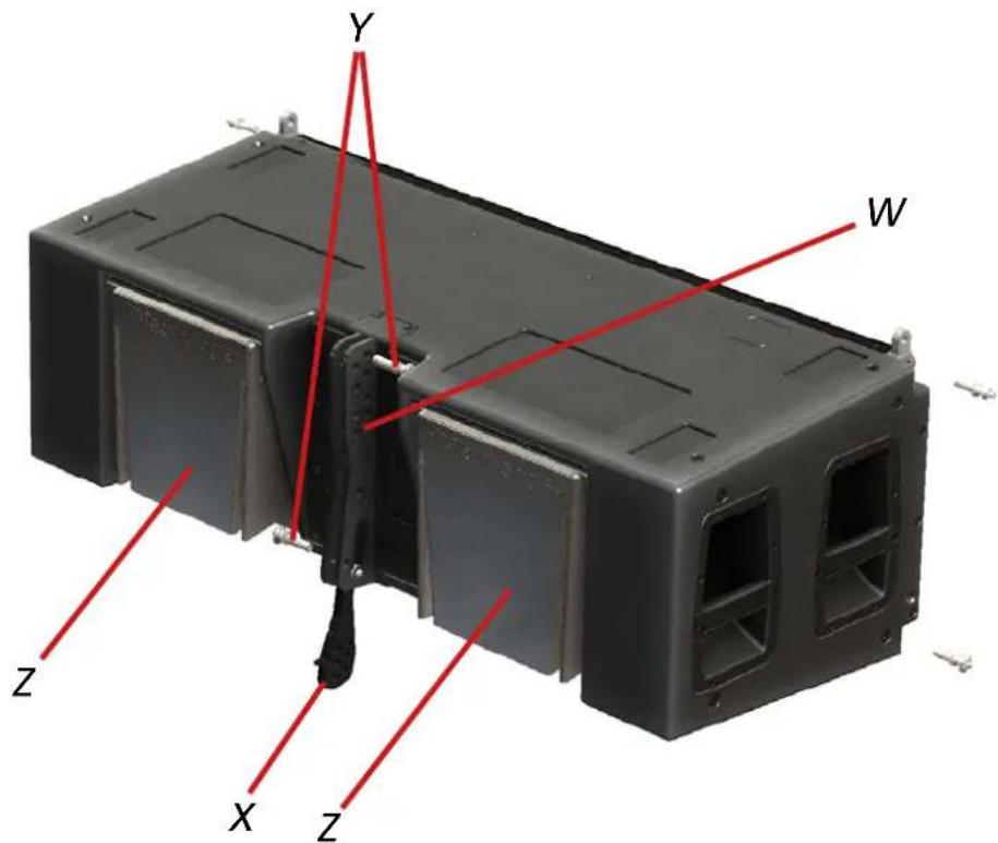
W- STAFFA POSTERIORE
X - GIUNTO MOBILE
Y - PIN DI FISSAGGIO POSTERIORI
Z - RAIN COVER
VIO-L212
Cod. 420120270 REV. 1.1
W
INSTALLAZIONE FLOWN
natural_image
Close-up of a black industrial control panel with visible buttons and ventilation grilles, no text or symbols present.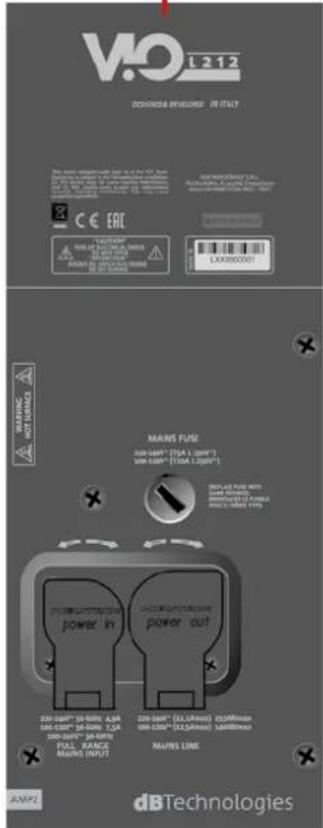
AMP2-ALIMENTAZIONE
AMP1-CONNECTIONI E CONTROLLO
![ViD L212 DESIGNED & DEVELOPED (IN ITALY) System Test USB Data Service Fork and Hold to test High Pass Filter [Hz] DSP Preset Status Analog Balanced Audio Ready Mouse/Prot Signal Unmitator Input Output /Line RDNet Expansion Card Reverse Private Active Active- List Data In Data Out MAINS 'USE' DESIGNED (SIA, SMT) SMA-NAME (SMA 1.64M3) dBTechologies AMP1](/content/2026/04/727944/images/0901bf6f69afa3392ae8ab1720272205c04d67c76977c9ed8391d5b9f3fbb286.jpg)
VIO-L212
Cod. 420120270 REV. 1.1
flowchart
graph TD
    A["Power Supply"] --> B["Amplifier Module"]
    B --> C["Preprocessor"]
    C --> D["DCP"]
    D --> E["CPU (Master)"]
    E --> F["RONET"]
    F --> G["NFC Internal Module"]
    G --> H["Remote Card"]
    G --> I["Remote Press"]
    G --> J["Remote Press Reset"]
    H --> K["Memory Format"]
    H --> L["Max/Min Format"]
    H --> M["Signal"]
    H --> N["Water Source"]
    H --> O["Water Source"]
    H --> P["Water Source"]
    H --> Q["Water Source"]
    H --> R["Water Source"]
    H --> S["Water Source"]
    H --> T["Water Source"]
    H --> U["Water Source"]
    H --> V["Water Source"]
    H --> W["Water Source"]
    H --> X["Water Source"]
    H --> Y["Water Source"]
    H --> Z["Water Source"]
    H --> AA["Water Source"]
    H --> AB["Water Source"]
    H --> AC["Water Source"]
    H --> AD["Water Source"]
    H --> AE["Water Source"]
    H --> AF["Water Source"]
    H --> AG["Water Source"]
    H --> AH["Water Source"]
    H --> AI["Water Source"]
    H --> AJ["Water Source"]
    H --> AK["Water Source"]
    H --> AL["Water Source"]
    H --> AM["Water Source"]
    H --> AN["Water Source"]
    H --> AO["Water Source"]
    H --> AP["Water Source"]
    H --> AQ["Water Source"]
    H --> AR["Water Source"]
    H --> AS["Water Source"]
    H --> AT["Water Source"]
    H --> AU["Water Source"]
    H --> AV["Water Source"]
    H --> AW["Water Source"]
    H --> AX["Water Source"]
    H --> AY["Water Source"]
    H --> AZ["Water Source"]
    H --> BA["Water Source"]
    H --> BB["Water Source"]
    H --> BC["Water Source"]
    H --> BD["Water Source"]
    H --> BE["Water Source"]
    H --> BF["Water Source"]
    H --> BG["Water Source"]
    H --> BH["Water Source"]
    H --> BI["Water Source"]
    H --> BJ["Water Source"]
    H --> BK["Water Source"]
    H --> BL["Water Source"]
    H --> BM["Water Source"]
    H --> BN["Water Source"]
    H --> BO["Water Source"]
    H --> BP["Water Source"]
    H --> BQ["Water Source"]
    H --> BR["Water Source"]
    H --> BS["Water Source"]
    H --> BT["Water Source"]
    H --> BU["Water Source"]
    H --> BV["Water Source"]
    H --> BW["Water Source"]
    H --> BX["Water Source"]
    H --> BY["Water Source"]
    H --> BZ["Water Source"]
    H --> CA["Water Source"]
    H --> CB["Water Source"]
    H --> CC["Water Source"]
    H --> CD["Water Source"]
    H --> CE["Water Source"]
    H --> CF["Water Source"]
    H --> CG["Water Source"]
    H --> CH["Water Source"]
    H --> CI["Water Source"]
    H --> CJ["Water Source"]
    H --> CK["Water Source"]
    H --> CL["Water Source"]
    H --> CM["Water Source"]
    H --> CN["Water Source"]
    H --> CO["Water Source"]
    H --> CP["Water Source"]
    H --> CQ["Power Supply"]
    C --> D
    D --> E
    E --> F
    F --> G
    G --> H
VIO-L212 Cod. 420120270 REV..1.1
- INGRESSO E RILANCIO AUDIO ("Balanced audio")
VIO-L212
Cod. 420120270 REV. 1.1
| TIPO LED | FASE DI ACCENSIONE DELLO SPEAKER | IN FUNZIONE NORMALE | WARNING GENERICO | BLOCCO PER ANOMALIA DELLO SPEAKER |
| LIMITER SPENTO | SPENTO, SI | ACCENDE SOLO IN CASO DI INTERVENTO | LAMPEGGIO MOMENTANEO | LAMPEGGIO CICLICO CONTINUO |
| SIGNAL | SPENTO LAMPEGGIO | IN PRESENZA DI SEGNALE | SEGNALAZIONE NORMALE DI AUDIO IN INGRESSO | SPENTO |
| MUTE/PROT | ACCESO PER QUALCHE SECONDO | SPENTO LAMPEGGIO | MOMENTANEO | ACCESSO FISSO |
| READY SPENTO | ACCESO FISSO ACCESO FISSO | SPENTO |
![MONITORING PRESET GROUP LOAD/SAVE LOG INCLINOMETER IN ATT 0.0.0 VIO L212 [1] +20 0 -10 0 -30 -20 -50 -40 -70 -60 ACOUSTIC INFO ATTENUATION: 0.0 dB HPF: FULL R. Hz COUPLING: A HF COMP: 1 TILT: 0 ° AMPLIFIERS INFO AMP1 AMP2 TEMP: 0 0 °C PSU TEMP: 0 0 °C PSU FREQ: 0 0 Hz MUTE SOLO TEST IDENTIFY LF MF HF OUT -20 -20 -20 -20 0 0 0 0 0 -20 -20 -20 -20 -40 -40 -40 -40 -∞ -∞ -∞ -∞ M M M S S S -∞](/content/2026/04/727944/images/346e7d930a16f8f6dc4630e67f96d8b7a1b4d362e62f18bed504bb6edf0291bd.jpg)
VIO-L212
Cod. 420120270 REV. 1.1
5. PARAMETRI DSP PRESET
natural_image
Three black industrial containerized units with red wheels, displayed side by side (no visible text or symbols)VIO-L212 Cod. 420120270 REV..1.1
MONTAGGIO DEL LINE-ARRAY E CABLAGGIO
VIO-L212 Cod. 420120270 REV..1.1

VIO-L212
Cod. 420120270 REV. 1.1
natural_image
Architectural elevation drawing of a multi-level building facade with circular windows and structural beams (no text or symbols)
natural_image
Technical line drawing of a vertical structural component with circular cutouts and internal channels (no text or symbols)VIO-L212 Cod. 420120270 REV..1.1
natural_image
Technical line drawing of two rectangular electronic or mechanical components with mounting brackets (no text or symbols)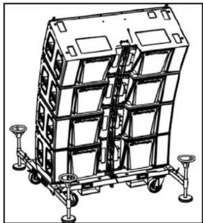
natural_image
Technical line drawing of a multi-tiered industrial container or storage unit with wheels and structural panels (no text or symbols)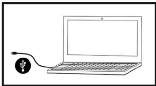
natural_image
Simple line drawing of a laptop connected to a USB cable (no text or symbols)PRODUCT OVERVIEW....31
MECHANICAL AND ACOUSTICAL FEATURES....32
ACOUSTICAL FEATURES....32
MECHANICS AND MAIN EQUIPMENT.... 33
2. LOCAL CONTROLS AND CONNECTIONS....36
3. ACOUSTIC PREDICTION AND MECHANICAL TESTING: DBTECHNOLOGIES COMPOSER40
4. AURORA NET 42
5. DSP PRESET PARAMETERS ....43
6. ACCESSORIES, INSTALLATION, CONFIGURATION ....44
FLY-BAR DRK-212 44
MOUNT SOCKETS FOR DIFFERENT MODELS 44
DOLLIES....44
ACOUSTIC PREDICTION / MECHANICAL TESTING....45
PREPARATION OF THE FLY-BAR AND MODULES....45
LINE-ARRAY ASSEMBLY AND WIRING 46
EXAMPLES OF MIXED CONFIGURATIONS....49
EXAMPLES OF STACKED CONFIGURATIONS ....50
7. TROUBLESHOOTING....51
8. FIRMWARE UPDATES....52
9. SPECIFICATIONS....53
GENERAL 53
ACOUSTICAL SPECIFICATIONS....53
AMPLIFIER 53
PROCESSOR....54
USER INTERFACE 54
INPUTS AND OUTPUTS....54
SOFTWARE COMPATIBILITY 54
POWER SUPPLY SPECIFICATIONS (ABSORPTION) 55
MECHANICAL SPECIFICATIONS 55
VIO-L212
Code 420120270 REV. 1.1
1. GENERAL INFORMATION
WELCOME!
Thanks for purchasing a product designed and developed in Italy by dBTechnologies! This powerful active line-array, suitable for the most demanding live performances, is the result of years of experience in the field of sound reinforcement. It makes use of innovative optimized sound, electronic and material research solutions.
PRODUCT OVERVIEW
The VIO-L212 3-way active line-array module marks a new era in the research and optimization field for large-sized indoor and outdoor professional live applications. The key features are:
- optimization between full-range acoustic performance and sizes
- a 3-point integrated rigging system for an efficient assembly/disassembly
• professional accessory line specific for handling and assembly - amplification section comprising 2 DIGIPRO G4 1600 W RMS each, controlled by DSP at 32 bits (special FIR filtering)
- ADC Floating technology, developed for a perfect isolation from interference, noise or hums, of the audio input
- DSP control and real-time filtering with FIR filters
• power, audio and mains daisy chains for optimized wiring - on-board RDNet control, pre-set for AoIP Audinate DanteTM protocol
- predictive and remote management software (DBTECHNOLOGIES COMPOSER, EASE, EASE FOCUS 3, AURORA NET)
MECHANICAL AND ACOUSTICAL FEATURES
ACOUSTICAL FEATURES
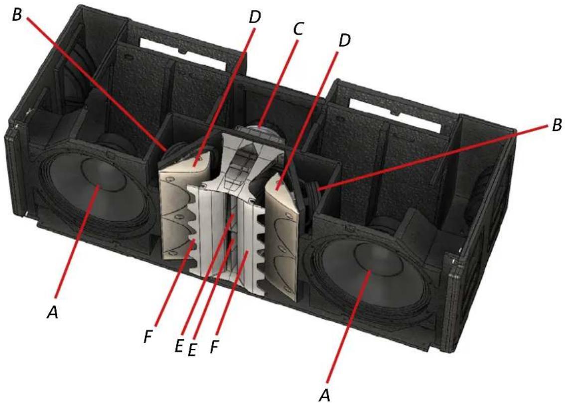
A - [LF] 2 Neodymium Woofer with a 12" diameter, 3" voice coil (reflex configuration).
B - [MF] 4 Neodymium Mid-Range with a 6.5" diameter, 2" voice coil.
C - [HF] 2 Neodymium Compression Driver, 1.4" exit throat, 3" titanium diaphragm (horn driver).
D - Phase plug with optimized chamber
E - Waveguides
F - Profiles with horn's logarithmic trend
VIO-L212's acoustic optimization harmonizes performance (SPL, phase and frequency response, sound focus) with design sizes and mechanical constraints.
Especially:
• the phase plugs [D] with optimized chamber increase the mid-frequency consistency
- the positioning and the distance of Mid-Range transducers contribute to clearly defined sound focus and off-axis listening position
- the logarithmic trend profiles [F] of the horn, avoid among others, the creation of constant reflections (modes) and increase the consistency of the mid-high section
• the waveguides [F] control the vertical directivity of high frequencies
VIO-L212
Code 420120270 REV. 1.1
MECHANICS AND MAIN EQUIPMENT
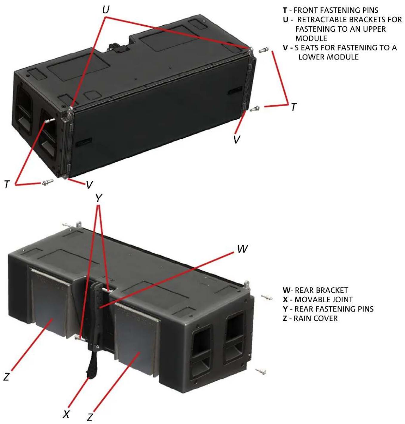
T - FRONT FASTENING PINS
U - RETRACTABLE BRACKETS FOR FASTENING TO AN UPPER MODULE
V - S EATS FOR FASTENING TO A LOWER MODULE
W- REAR BRACKET
X - MOVABLE JOINT
Y - REAR FASTENING PINS
Z - RAIN COVER
The 3-point fastening system uses, by means of pins:
• the upper brackets U, on the front side
• the lower seats V, on the front side
- the W bracket, with movable joint X, on the rear side.
For simplicity's sake the next images are no longer shown with the rain covers [Z].
VIO-L212 Code 420120270 REV. 1.1
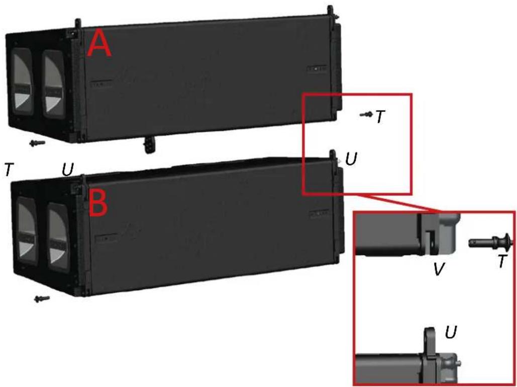
For fastening two modules:
FRONT SIDE
1) On the B module move the U brackets upwards and fasten them with the related pins.
2) Remove the T pins from module A
3) Move the 2 modules close to one another inserting the U brackets in the V seats.
4) Insert the T pins completely. By doing this the A and B modules at the front are blocked.
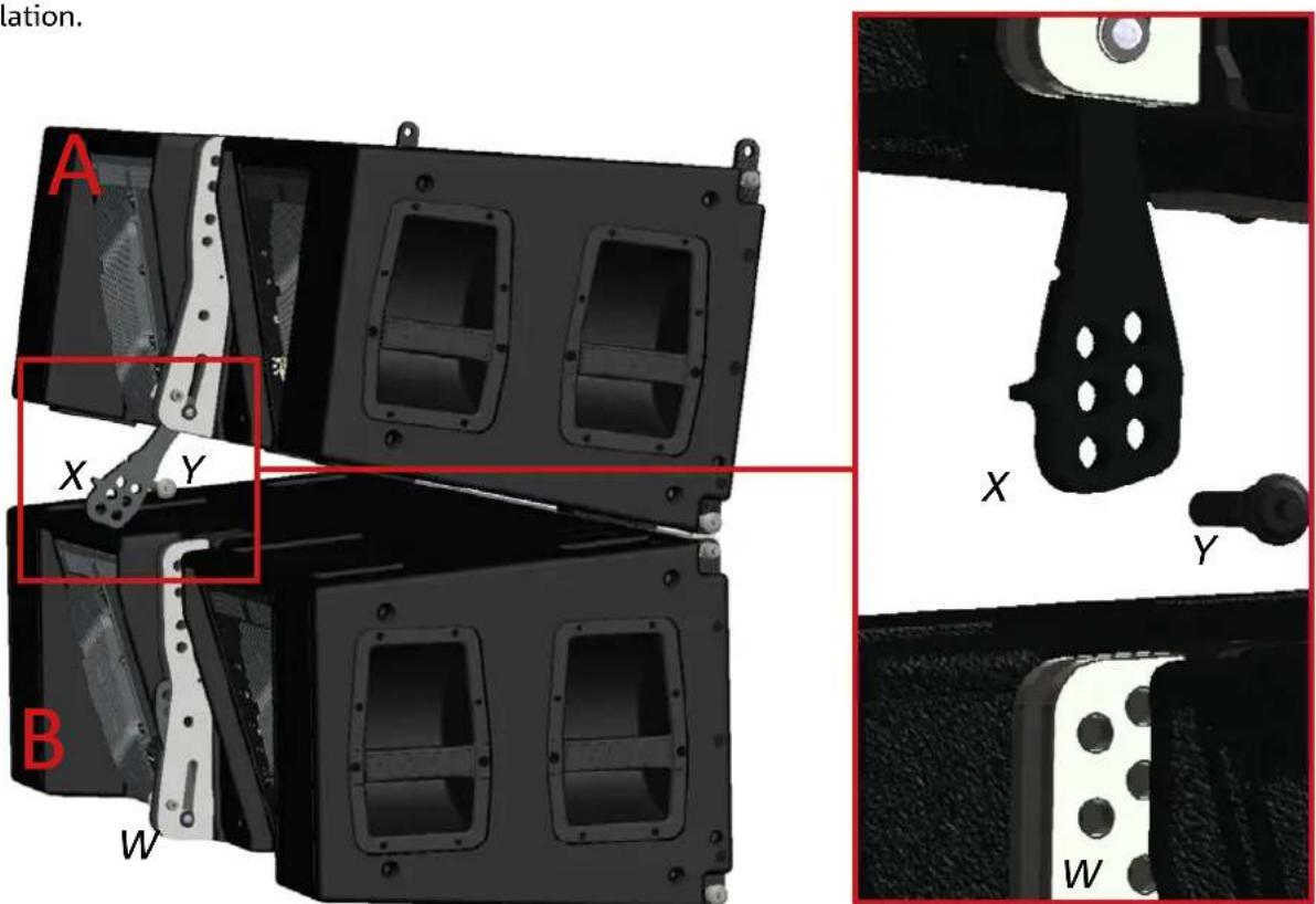
REAR SIDE
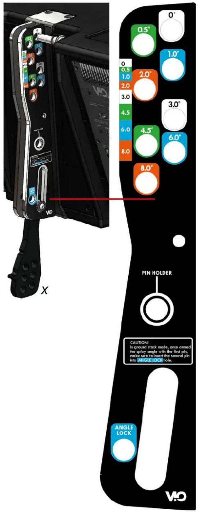
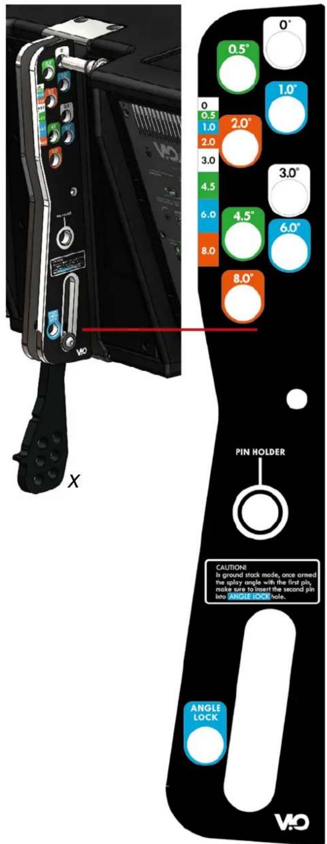
5) On module A release the movable joint X. Then insert the Y pin in the hole that corresponds to the desired tilt.
The details describing this operation are shown in the next page. They are different depending on the FLOWN or STACK installation.
VIO-L212
Code 420120270 REV. 1.1
W
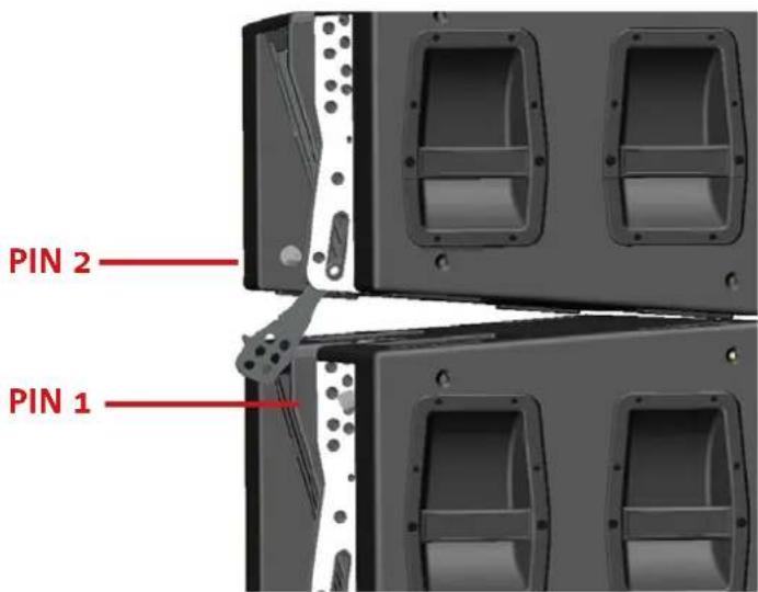
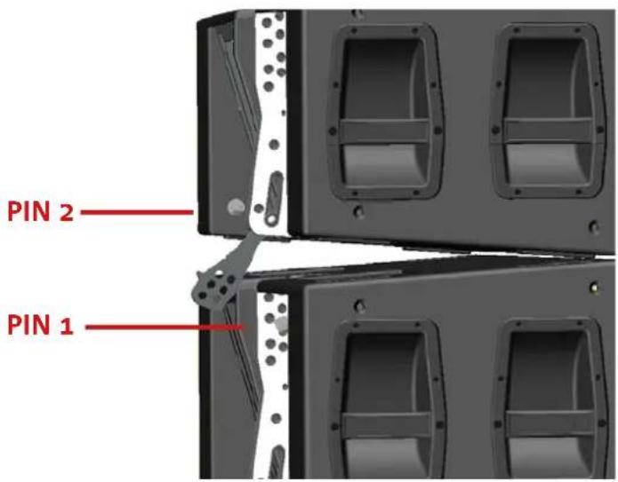
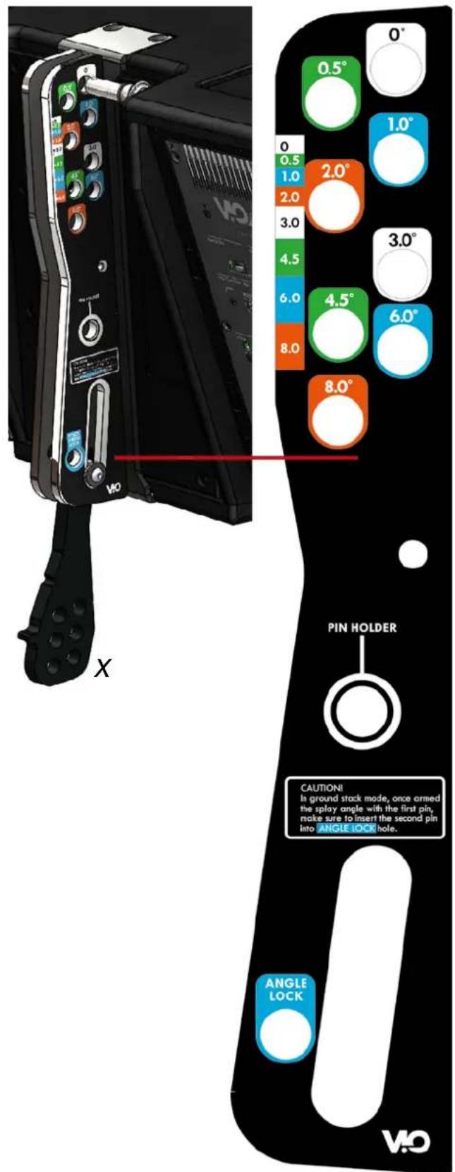
FLOWN INSTALLATION
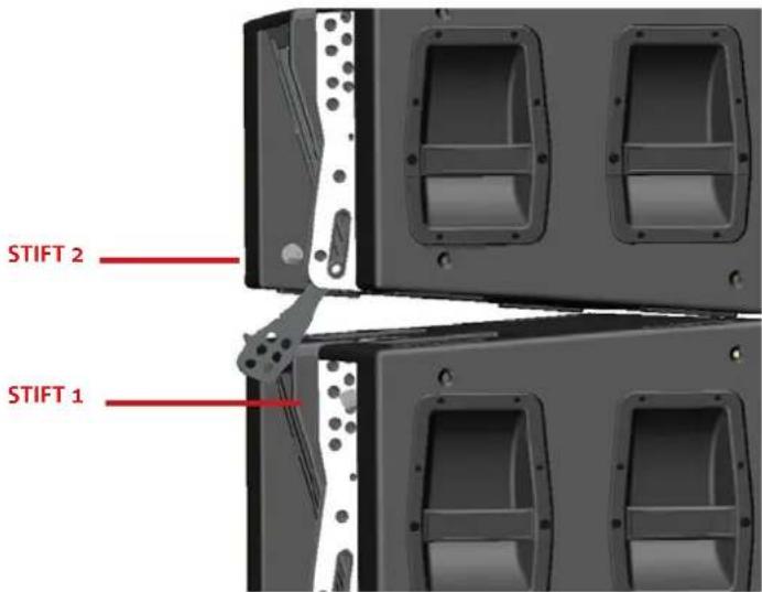
Only one pin (PIN 1) is required to fasten the angle at the back. The differently coloured inserting holes of the W bracket, allow the following tilting: [0irc, 0.5irc, 1irc, 2irc, 3irc, 4.5irc, 6irc, 8irc] . The bracket slot allows inserting the pin without lifting the rear of VIO-L212.
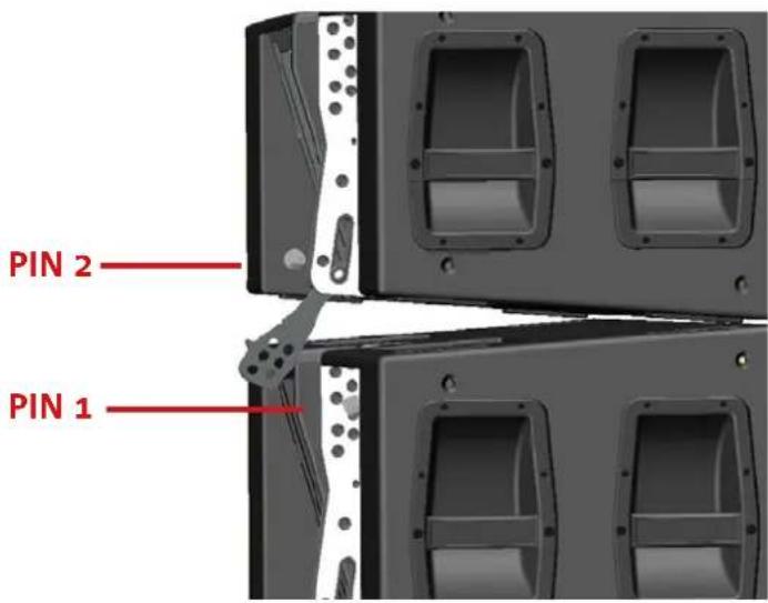
STACKED INSTALLATION
Two pins (PIN1, PIN2) are necessary to fasten the angle at the back. Once PIN1 has been introduced, according to the FLOWN procedure, the rear of VIO-L212 lifts as much as the slot allows it and the position is secured with PIN2.
VIO-L212 Code 420120270 REV. 1.1
2. LOCAL CONTROLS AND CONNECTIONS
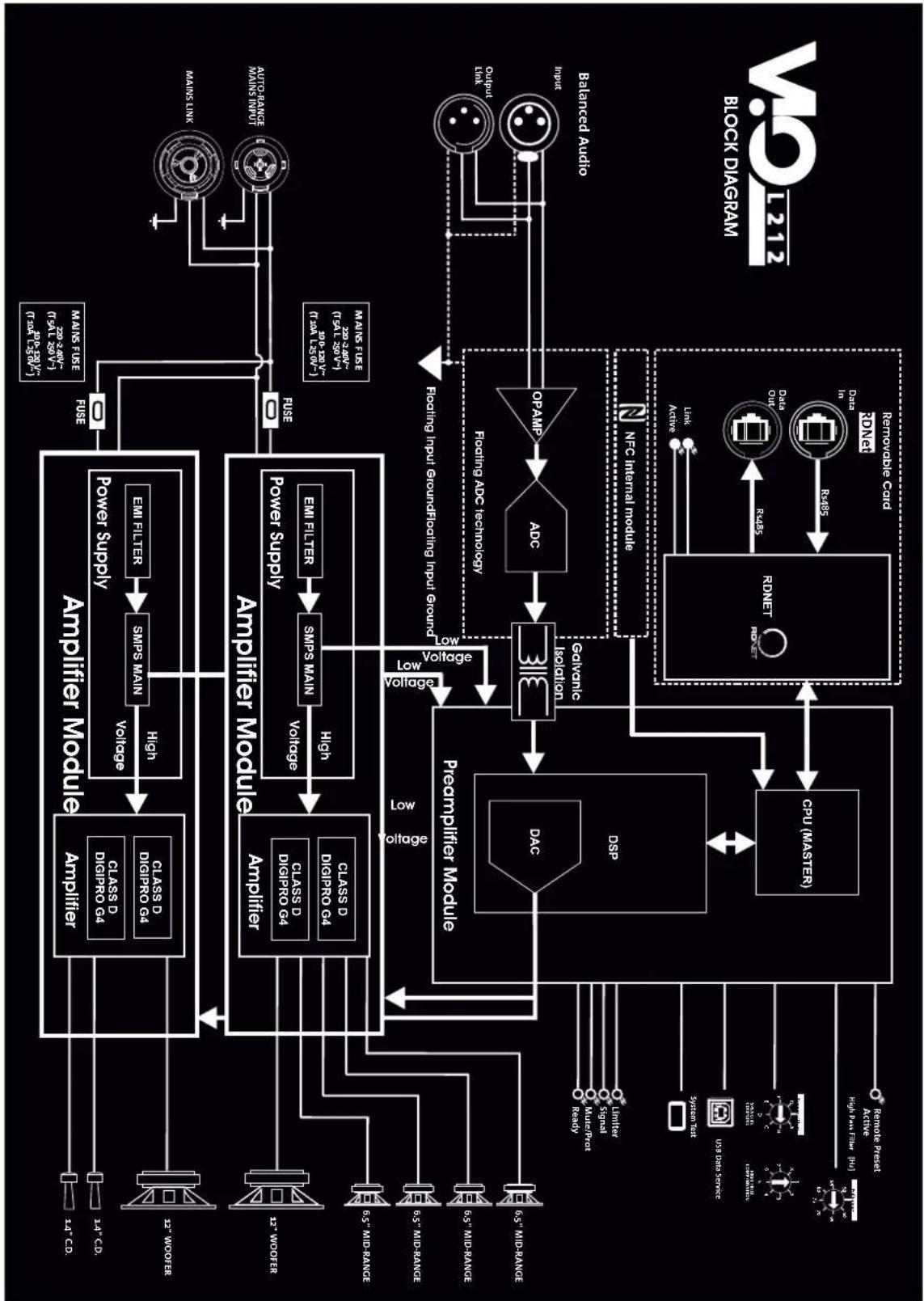
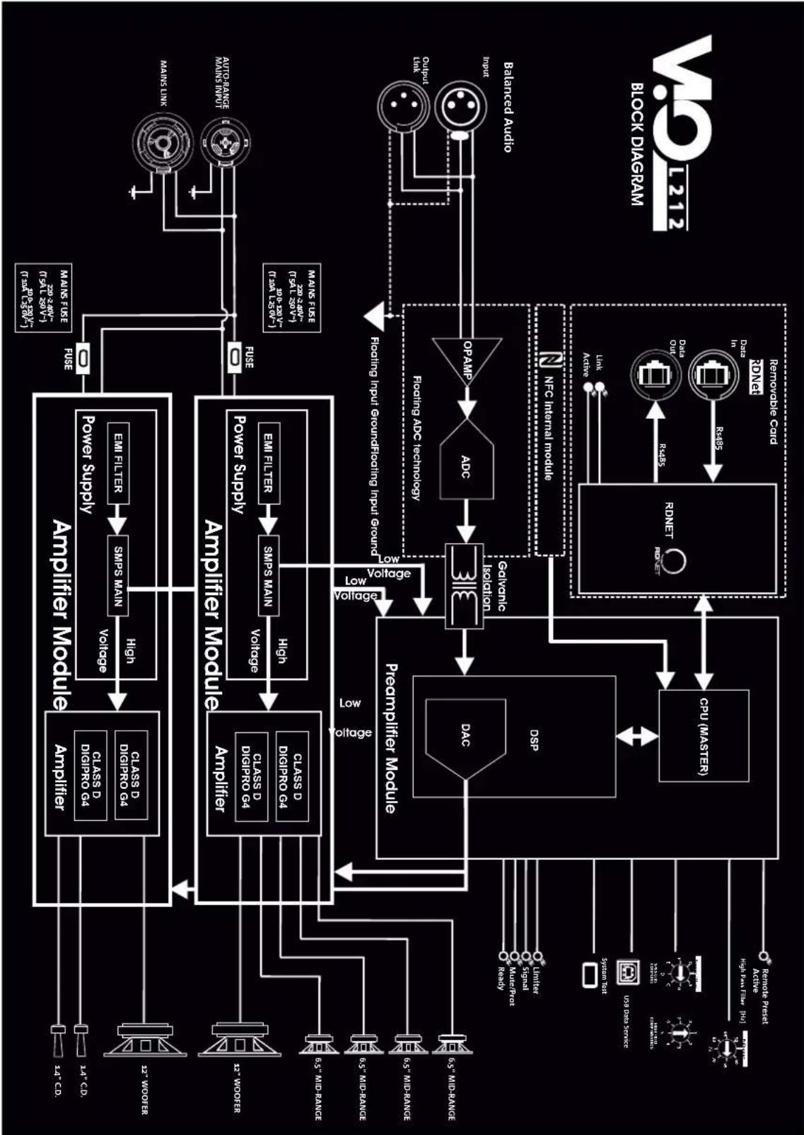
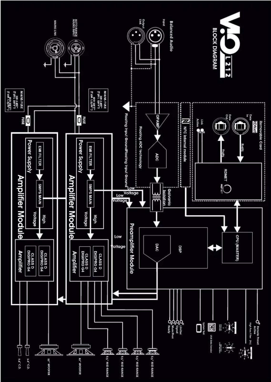
The 2 DIGIPRO G4 amplifiers can supply up to 3200 W RMS. The block diagram of electronics of VIO-L212 is illustrated in the next page.
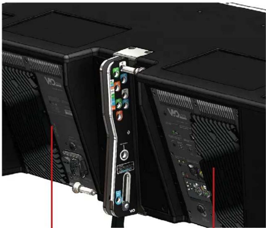
The two main sections, present at the rear of the module, and protected by the specific rain covers (not shown here) are:
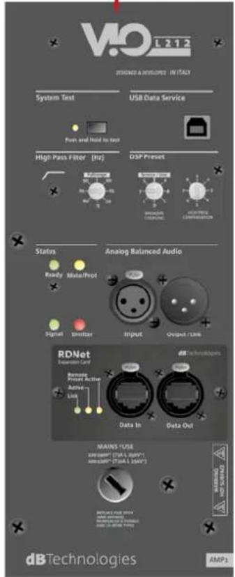
• CONNECTIONS AND CONTROL
- POWER SUPPLY
The CONNECTIONS AND CONTROL section uses a DSP that controls, among others, the output signal FIR filtering.
The POWER SUPPLY section uses a PFC which improves its efficiency and protects the amplification section from undesired oscillations of the input power supply.
FIR FILTERING
Sound equalization is controlled by a 32-bit DSP. The implemented FIR filters minimize the phase distortion of the equalized signal. For more equalization information, please refer to paragraph: "DSP PRESET PARAMETERS".
PFC
The power factor correction (PFC) reduces the out of phase condition between current and voltage supplied to the amplifier. Within a certain range the input power supply is ideal, regardless of small variations in the power supply before the system. For more information concerning power supply suggestions, please refer to section: "LINE-ARRAY ASSEMBLY AND CONNECTIONS".
natural_image
Close-up of black hardware units with visible ports and connectors, no readable text or symbols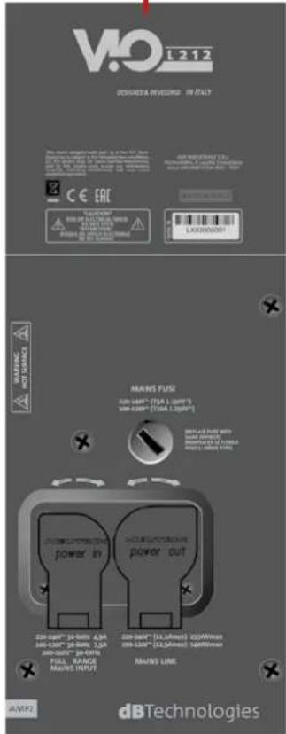
AMP2-POWER SUPPLY
AMP1-CONNECTIONS AND CONTROL
VIO-L212
Code 420120270 REV. 1.1
flowchart
graph TD
    A["Power Supply"] --> B["Amplifier Module"]
    B --> C["Prepumpifier Module"]
    C --> D["NFC Internal Module"]
    D --> E["Removable Card"]
    E --> F["Output Audio"]
    F --> G["Max Line"]
    G --> H["Auto-Range Max Input"]
    H --> I["Max Line"]
    I --> J["Power Supply"]
    J --> K["Amplifier Module"]
    K --> L["Prepumpifier Module"]
    L --> M["Removable Card"]
    M --> N["Output Audio"]
    N --> O["Max Line"]
    O --> P["Power Supply"]
    P --> Q["Amplifier Module"]
    Q --> R["Prepumpifier Module"]
    R --> S["NFC Internal Module"]
    S --> T["Output Audio"]
    T --> U["Max Line"]
    U --> V["Power Supply"]
    V --> W["Amplifier Module"]
    W --> X["Prepumpifier Module"]
    X --> Y["NFC Internal Module"]
    Y --> Z["Output Audio"]
    Z --> AA["Max Line"]
    AA --> AB["Power Supply"]
    AB --> AC["Amplifier Module"]
    AC --> AD["Prepumpifier Module"]
    AD --> AE["NFC Internal Module"]
    AE --> AF["Output Audio"]
    AF --> AG["Max Line"]
    AG --> AH["Power Supply"]
    AH --> AI["Amplifier Module"]
    AI --> AJ["Prepumpifier Module"]
    AJ --> AK["NFC Internal Module"]
    AK --> AL["Output Audio"]
    AL --> AM["Max Line"]
    AM --> AN["Power Supply"]
    AN --> AO["NFC Internal Module"]
    AO --> AP["Output Audio"]
    AP --> AQ["Max Line"]
    AQ --> AR["Power Supply"]
    AR --> AS["NFC Internal Module"]
    AS --> AT["Output Audio"]
    AT --> AU["Max Line"]
    AU --> AV["Power Supply"]
VIO-L212 Code 420120270 REV. 1.1
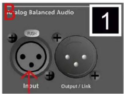
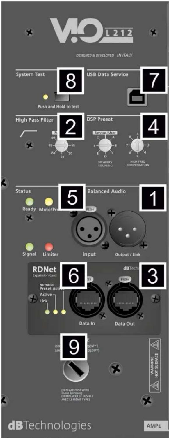
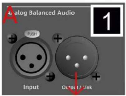
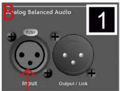
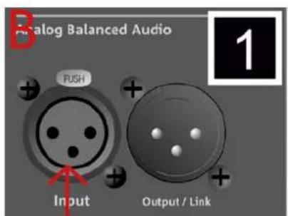
- INPUT AND OUTPUT LINK ("Balanced audio")
Input and output compatible with balanced XLR cables.
In particular, "Input" is used to connect with the audio signal coming from the mixer or from another loudspeaker, "Output Link" is used to link the signal to the other modules of the line-array, in daisy-chain configuration.
- HIGH PASS FILTER
It enables to apply directly a high-pass filter (not applied, the stand-by position is Fullrange). Specifically the cut-off frequencies may be chosen between: (60,65,70,75,80,85,90 Hz)
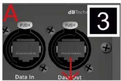
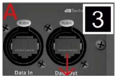
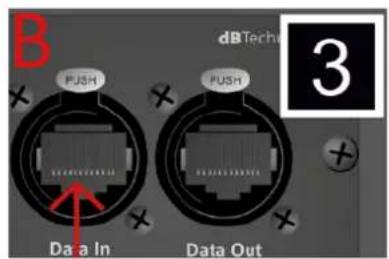
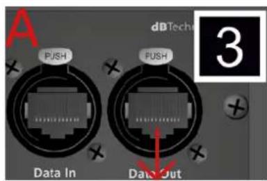
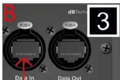
- INPUT AND NETWORK CONNECTION LINK RDNet
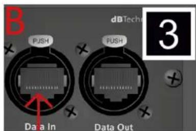
Section compatible with network cables with etherCON/RJ45 connectors.
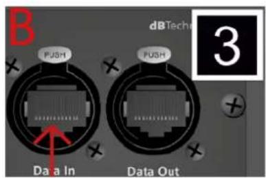
In particular, "Data in" must be connected to devices such as RDNet Control 2 or Control 8; "Data Out" is used to link the network to additional modules of the line array in daisy-chain configuration.
- DSP PRESET
Rotary for the acoustic setup of the line array.
It is advisable to use these controls (or the same parameters remotely via RDNet connection) to optimize the acoustic behaviour as a function of the number of modules and their aiming. An in-depth analysis on the use of “SPEAKER COUPLING” and “HIGH FREQUENCY COMPENSATION” can be found in the “DSP PRESET PARAMETERS AND REMOTE CONTROL” section.
- STATUS LEDs
LEDs relating to module operation. A table in next page summarizes the meaning of the different LEDs.
- CONTROL LEDs
LEDs relating to module network operation (RDNet).
In particular, if "Link" is on the RDNet network is active and has acknowledged the device, if "Active" is flashing there is data traffic, if "Remote Preset Active" is on all local control on the amplifier panel are by-passed by the RDNet remote control.
- SERVICE DATA USB PORT
It is a mini-USB B port to be used only for product firmware update. For further information refer to "FIRMWARE UPDATE".
- SYSTEM TEST
It carries out a test with sweep signal to check
woofer integrity. This test must not be considered as thorough, but just a first check in the analysis of any issues
- NETWORK FUSE
Housing for the network fuse of AMP1 section.
VIO-L212
Code 420120270 REV. 1.1
| LED TYPE | STARTING PHASE OF THE SPEAKER | IN NORMAL OPERATION | GENERIC WARNING | BLOCK FOR SPEAKER FAULT |
| LIMITER OFF | OFF, IT | STARTS ONLY IN CASE OF TRIGGERING | TEMPORARY FLASHING | CONTINUOUS CYCLIC FLASHING |
| SIGNAL | OFF FLASHING | IN THE PRESENCE OF A SIGNAL | INPUT AUDIO NORMAL WARNING | OFF |
| MUTE/ PROT | ON FOR A FEW SECONDS | OFF TEMPORARY | FLASHING | STEADY ON |
| READY OFF | STEADY ON STEADY ON OFF |
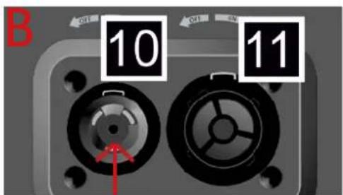
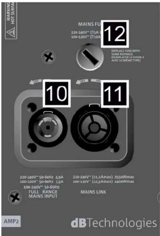
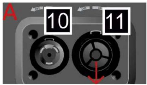
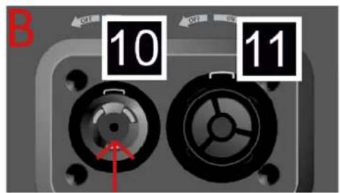
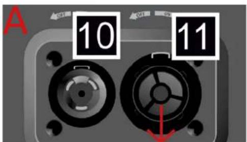
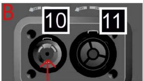
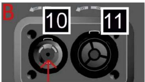
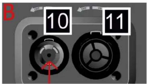
10. "MAINS INPUT" POWER CONNECTOR
Compatible with powerCON TRUE1® connector, the power supply features an auto-range function. Once the appropriate range has been defined and the fuse has been changed, if necessary, the system automatically recognizes the voltage within the range [100-120V\~] or [220-240V\~].
11. "MAINS LINK" POWER DAISY CHAIN
Compatible with powerCON TRUE1 ® connector for power daisy chain to other modules.
To find the maximum number of modules that can be connected in a re-linked system, see the TECHNICAL
SPECIFICATIONS section.
12. NETWORK FUSE
Housing for the network fuse of AMP2 section.
VIO-L212 Code 420120270 REV. 1.1
3. ACOUSTIC PREDICTION AND MECHANICAL TESTING: DBTECHNOLOGIES COMPOSER
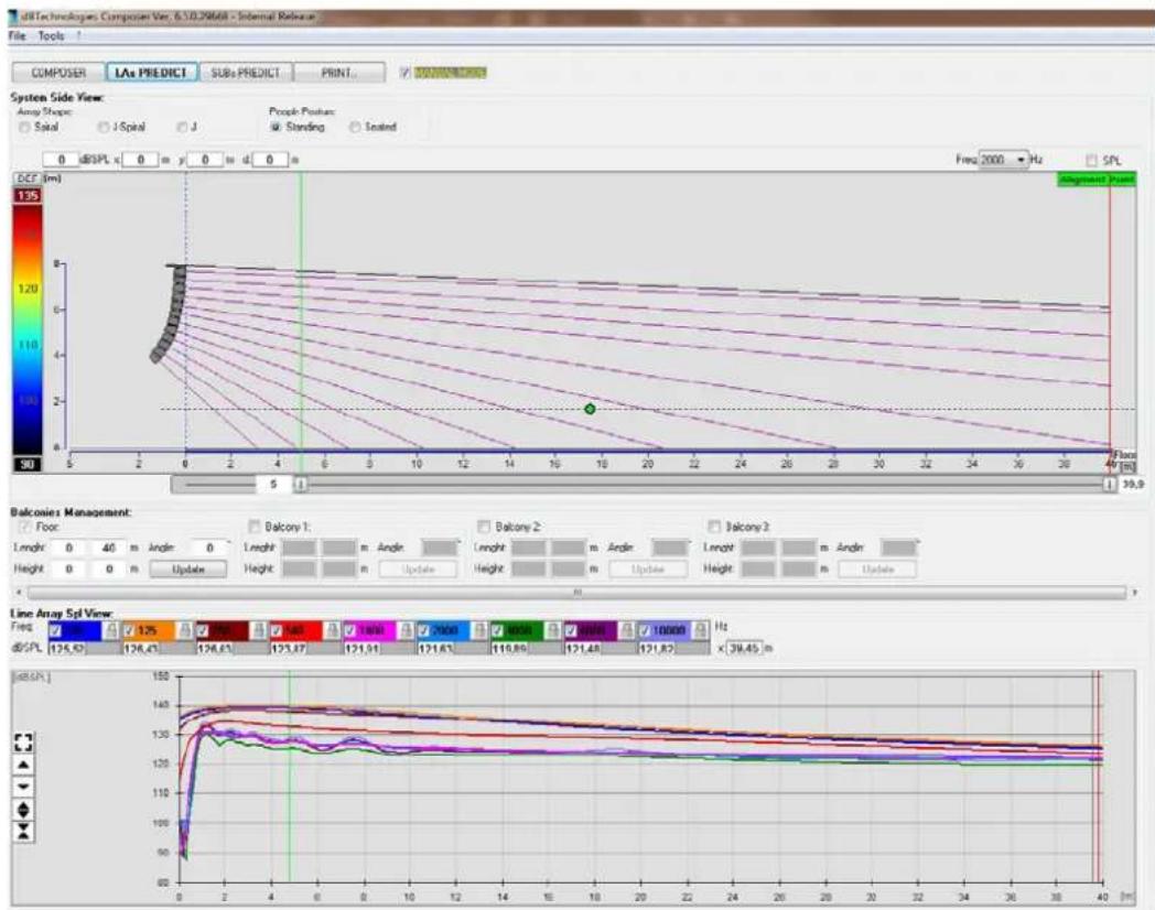
dBTechologies Composer software, available for free download from www.dbtechnologies.com, is a tool for the proper designing of the audio systems, recommended for the entire VIO series.
It offers a solution for the spaces to sonorize, indicating the angle of the line-array modules in order to achieve the desired coverage and the preset to use.
Besides being a predictive instrument, it also allows several manual adjustments to further improve the configuration based on possible audio measurements made on the field or on special needs.
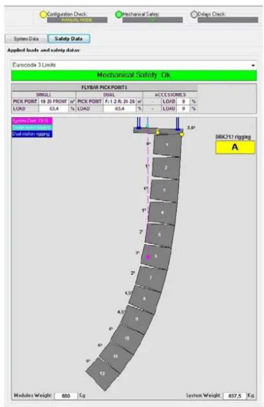
It is also the effective tool to assess installation safety level. In fact, thanks to the simulation of the fly-bar's static behaviour and an indication of the mechanical forces at play, it allows verifying how many modules should be installed before reaching an overload condition.
The main sections of dBTechnologies Composer are:
• COMPOSER - overview allowing to enter design start data
- LAs PREDICT - with the simulation, configuration and safety check of the line-arrays
- SUBs PREDICT - with the simulation, configuration and safety check of the subwoofers
This chapter describes some of the software's details relating to installation and safety, in particular for the FLOWN configuration of VIOL212 line arrays.
VIO-L212
Code 420120270 REV. 1.1
The LAs PREDICT section contains all the information necessary for the proper configuration, flown or stack, of a VIO system. To access it, you need to first enter the project's data, included in the Composer section.
The System Data sub-page provides the following suggestions: the angulation of the various modules, various parameters relating to the “DSP preset” section and the angulation of the DRK-212 fly-bar. This last angulation can be detected on the field with the use of a laser inclinometer, not included, the assembly of which is illustrated in the DRK-212 manual.
![Configuration Check MANUAL NAME Mechanical Safety Delay Check: System Data Safety Data Line Array Eats N° Model Angle (°) SPEAKERS COMPLYING HIGH TREQ COMP. Delay [ms] Shape Weight [kg] Flybar 1 VIOL212 -7,5 — — — — — 37,5 Box# 1 VIOL212 6 D 7 6 — 88 Box# 2 VIOL212 1 D 7 6 — 88 Box# 3 VIOL212 1 D 7 6 — 88 Box# 4 VIOL212 1 D 7 6 — 88 Box# 5 VIOL212 3 D 3 6 — 55 Box# 6 VIOL212 3 D 3 6 — 55 Box# 7 VIOL212 3 D 2 6 — 55 Box# 8 VIOL212 4,5 D 2 6 — 55 Box# 9 VIOL212 4,5 D 2 6 — 55 Box# 10 VIOL212 6 D 2 6 — 55 Box# 11 VIOL212 6 D 2 6 — 55 Box# 12 VIOL212 6 D2 6 — 55](/content/2026/04/727944/images/8f3ccf8fcb24463b85f4b63ea46395174c9a446a9774b35d3e0cd0cfc2beac2b.jpg)
VIO-L212 Code 420120270 REV. 1.1
4. AURORA NET
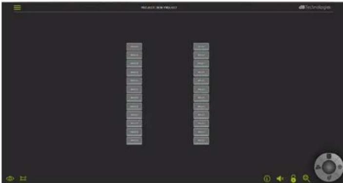
AURORA NET, is a remote control software with the following features:
• multi-platform (Windows /MAC OS X)
- it allows a more accurate control of the parameters and their history during an event
- it allows a flexible management even in the case of large fixed/live installations (with advanced group control)
- it allows recalling various presets
- is optimized for usability and speed of data displaying.
For further information, refer to the software complete manual.
![MONITORING PRESET GROUP LOAD/SAVE LOG INCLINOMETER IN ATT 0.0.0 VIO L212 [1] +20 0 -10 0 -30 -20 -50 -40 -70 -60 -∞ ACOUSTIC INFO ATTENUATION: 0.0 dB HPF: FULL R. Hz COUPLING: A HF COMP: 1 TILT: 0 ° AMPLIFIERS INFO AMP1 AMP2 TEMP: 0 0 °C PSU TEMP: 0 0 °C PSU FREQ: 0 0 Hz MUTE SOLO TEST IDENTIFY LF MF HF OUT 0 0 0 0 -20 -30 -20 -20 0 0 0 0 -20 -20 -20 -20 -40 -40 -40 -∞ -∞ -∞ M M M S S S -∞](/content/2026/04/727944/images/6d11b8de8d589f7cf4553b7055ccb7ca733fb4990f3120a7161fe4951fc89e31.jpg)
VIO-L212
Code 420120270 REV. 1.1
5. DSP PRESET PARAMETERS
The use of a line array has a number of advantages in different contexts, in particular:
- Homogeneous SPL along the front line of the speakers, an effect that is particularly noticeable over medium to long distances
- directional acoustic behaviour, which allows the sound to be accurately focused on the audience, avoiding unnecessary dispersion in areas where sound coverage is not required.
The achievable optimization of the line array takes into account the behaviour of the system with respect to frequency:
- increasing the distance to the line array increases air attenuation. This has an effect especially on the high frequencies.
• as the angle between the line array elements increases, the mid-frequency phase coupling decreases. - As the number of line array modules increases, the low frequencies will add up in an acoustically consistent manner.
The line array acoustic configuration of the VIO L212 modules can be optimized, thanks to the control functions managed by the DSP. The local user interface is simple and immediate: it uses two rotary of the "DSP Preset" section:
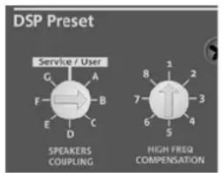
- Parameter calculation is carried out with dBTechnologies Composer. It is possible to select locally said parameters on the VIO-L212 panel and use the remote control through AURORA NET.
- Position the rotary "SPEAKER COUPLING" according to the number of modules used in the line array. This rotary acts on the low frequencies and must be set in the position:
- All these parameters can be adjusted with the remote control, once the RDNet connections have been properly made, using the free AURORA NET software. When using the remote control, the local controls on the panels of the VIO-L212 modules are by-passed.
For further information, refer to the software complete manual.
VIO-L212 Code 420120270 REV. 1.1
6. ACCESSORIES, INSTALLATION, CONFIGURATION
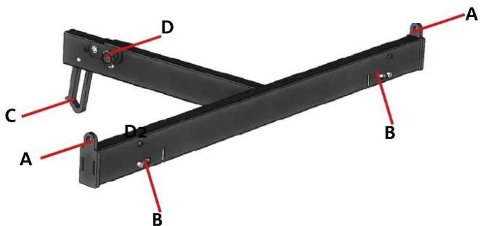
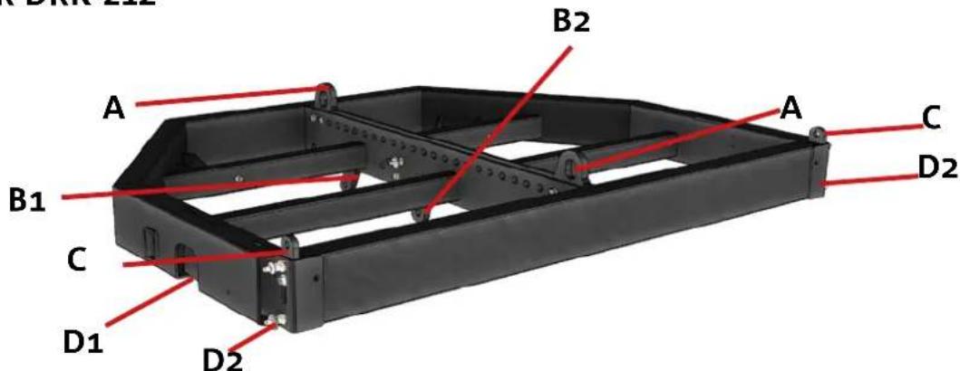
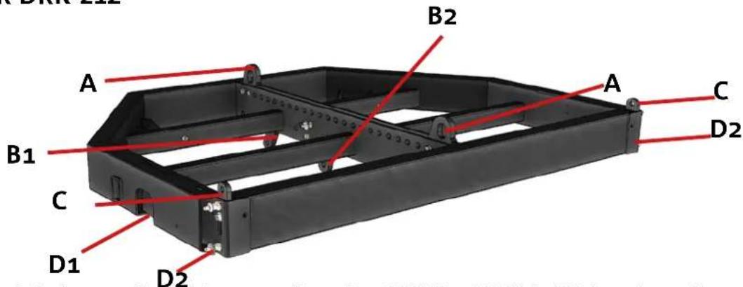
FLY-BAR DRK-212
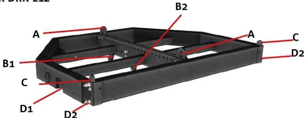
DRK-212 is the fly-bar for FLOWN and STACK use of VIO-L212. In FLOWN it may be used both with line-array angled downwards and upwards. For installation information, please refer to the specific instructions of the accessory.
• A - Motor lifting hooks
• B - FLOWN rear joint (depending on the configuration)
• C - Front retractable brackets for STACK use
• D - FLOWN front fastenings (depending on the configuration)
MOUNT SOCKETS FOR DIFFERENT MODELS
| NAME ADAPTED MODEL | |
| TF-VIO2 | VIOL210 |
DOLLIES
NAME USE TOP
| DT-VIOL212 | 1-4 VIOL212 | √ |
| DO-VIOL212 | 1 VIOL212 | ✕ |
| DT-DRK212 2 DRK212 (+ 2 TF-VIO2) | ✕ | |
VIO-L212
Code 420120270 REV. 1.1
ACOUSTIC PREDICTION / MECHANICAL TESTING
- Use DBTECHNOLOGIES COMPOSER to set project parameters.
- Make sure that the MECHANICAL SAFETY testing of the software confirms the safety of the selected configuration
- Make sure that the local parameters of the different modules are correctly set on the single amplifier panels. In particular, verify according to the project the Speaker Coupling and High Frequency Compensation settings. As an alternative, all parameters can be remotely edited in real time if the line-array connection is carried out through the RDNet network (DBTECHNOLOGIES NETWORK). Nevertheless, in this case, project initial settings should be physically repeated on the VIO-L210 modules before installation. For further information see the DSP PRESET PARAMETERS AND REMOTE CONTROL section.
PREPARATION OF THE FLY-BAR AND MODULES
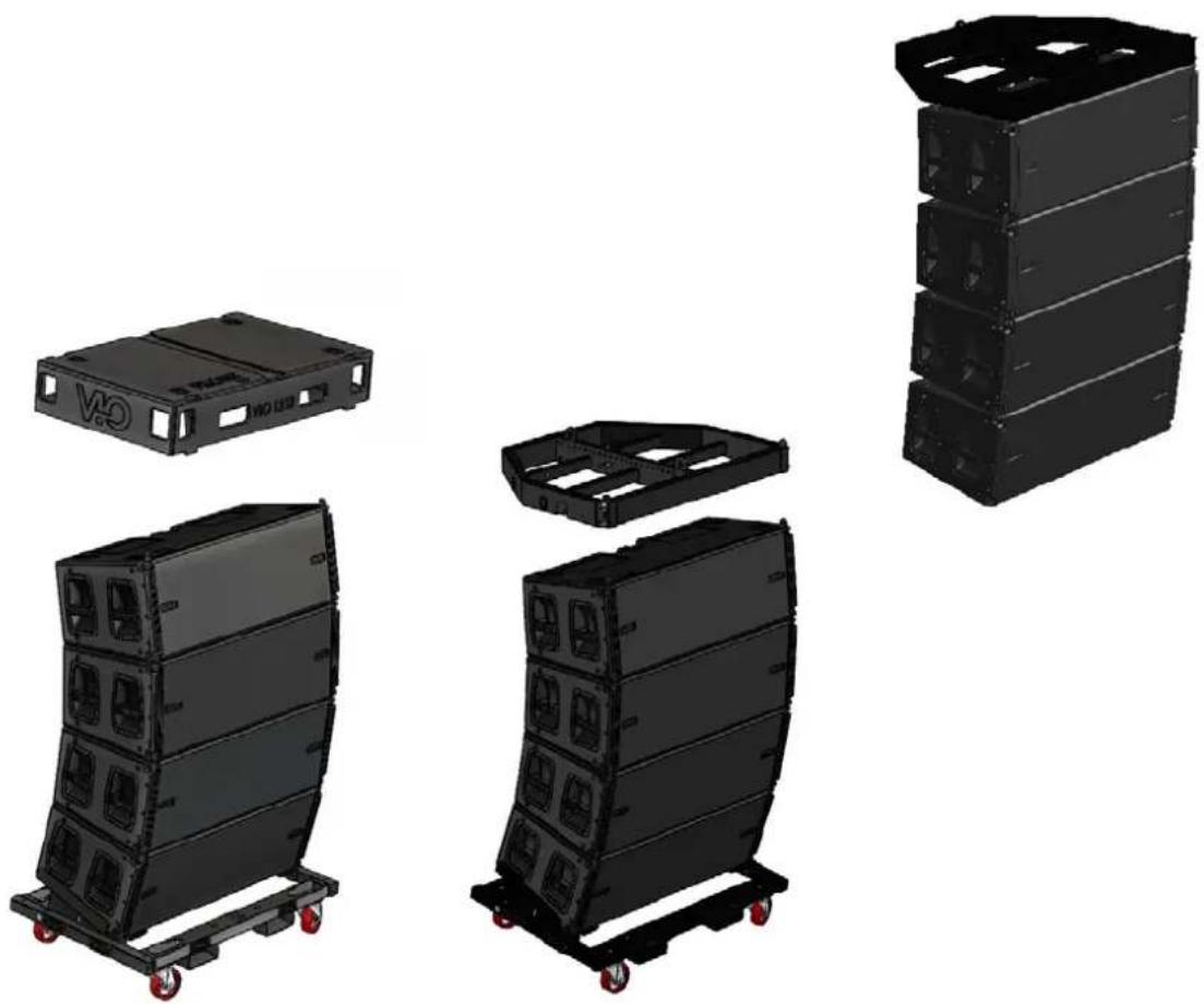
- Prepare the DRK212 fly-bars and the line-array VIO-L212 modules. This example shows dollies DT-DRK212 and DT-VIOL212 with DTT-VIOL212 tops. The configuration in the example, for illustrative purposes only, is an 8-module line-array.
natural_image
Three black industrial equipment chassis with red wheels, shown from different angles (no text or symbols visible)VIO-L212 Code 420120270 REV. 1.1
LINE-ARRAY ASSEMBLY AND WIRING
- Remove the safety strap and the top. At the rear of the modules insert the pins for the fastening of the angles calculated by the software.
- By means of motors, lift 1 fly-bar from the DT-DRK212 dolly and secure it in flown configuration to the upper VIO-L212 top.
- For the following connection make sure to route the necessary main wirings on the fly-bar.
- Connect the first individual modules, especially the re-linkable ones.
- Lift the upper part of the line-array
natural_image
Three black industrial storage units with red wheels, shown from different angles (top, front, and side) against a plain background.VIO-L212
Code 420120270 REV. 1.1
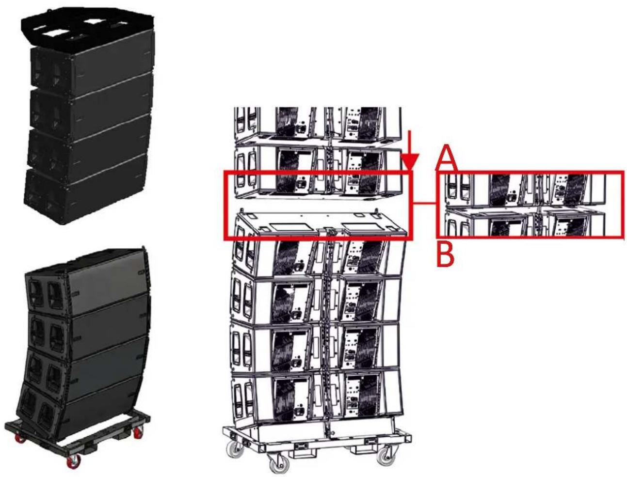
- Move the dolly with the rest of the 4 modules below the ones already lifted. Remove the belt and the top from the second dolly.
- Rig one module at a time and slightly lift/lower the ropes with the motors, initially with front installation and then with rear one, as shown in the MECHANICS AND MAIN EQUIPMENT section.
- Connect the modules with each other as the installation proceeds.
• End the composition and the line-array connections.

WARNING!
The product and accessories must be handled by experienced personnel only! Make sure that the installation is positioned in a stable and safe manner in order to avoid hazardous conditions for people, animals and/or objects. The user is required to follow regulations and mandatory laws on safety of the country in which the product is used. For safe use, regularly check the operation of all parts and integrity before use.
Design, calculations, installation, testing and maintenance of suspended systems or professional audio stacks must be performed by authorized personnel only. AEB Industriale is not responsible for improper installations, non-compliant with safety requirements.
VIO-L212 Code 420120270 REV. 1.1
INDICATIONS ON POWER SUPPLY AND BEHAVIOUR OF THE LINE-ARRAY SYSTEM
Please bear in mind that the system's power supply, with a correct source and wiring sizing, affects the correct operation of the modules and the system.
- The current supplied to the line-array module behaves dynamically (i.e. first start-up, idlecondition, fullrangeoperation).
- There are voltage drops due to cable length and cross-section. Generally these drops are directly proportional to the length and inversely proportional to the cable cross-section.
VIO-L212
Code 420120270 REV. 1.1
EXAMPLES OF MIXED CONFIGURATIONS
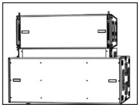
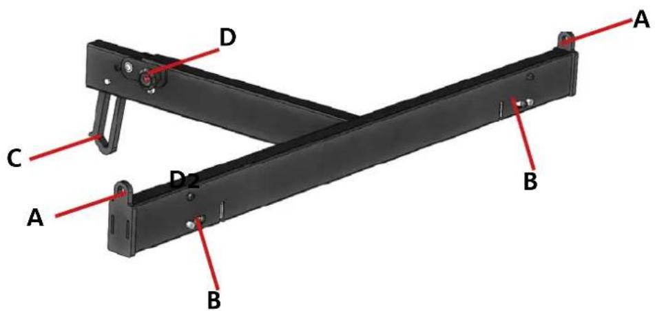
- Through the TF-VIO2 mount socket, it is possible to use a VIO-L210 line-array in down-fill function under one consisting of VIO-L212. The suggested proportion between the 2 models is 3:1 as shown here below, for illustrative purposes only.
• A - Front brackets for VIO-L212
• B - Front fastening systems for VIO-L210
• C - Rear joint for VIO-L210
• D - Rear coupling bracket for VIO-L212
natural_image
Architectural elevation drawing of a multi-level building facade with circular cutouts and structural elements (no text or symbols)
natural_image
Pure architectural or mechanical diagram with circular and rectangular elements, no text or symbols presentVIO-L212 Code 420120270 REV. 1.1
EXAMPLES OF STACKED CONFIGURATIONS
The main stack configurations are:
• on subwoofer (through DRK-212)
- directly on DT-VIOL212 dolly by using the compulsory EFK-1 accessory.
natural_image
Technical line drawing of two stacked rectangular electronic components with mounting brackets (no text or symbols)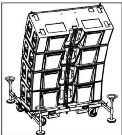
natural_image
Technical line drawing of a multi-tiered industrial storage unit with wheels and mounting feet (no text or symbols)For installation information and the configurations allowed, please refer to the manuals of individual accessories.
VIO-L212
Code 420120270 REV. 1.1
7. TROUBLESHOOTING
The module does not turn on:
- Check that power supply is present upstream of the installation.
- Check that the power supply or the re-link connection of the power supply is properly inserted.
- Make sure that wiring length and cross-section allow, including voltage drops, operating within the allowed range.
- Check any warning displayed by AURORA NET (in RDNet connection)
The module turns on but produces no sound:
- Check that the audio signal input connections or the audio signal re-links are properly carried out.
- Check that the audio source (mixer) is properly connected and active.
- Check via remote control through AURORA NET (in RDNet connection) that MUTE is not active. Check also any displayed warning.
Module sound is not fully satisfactory.
- Re-check the project, the installation and configuration specifications using DBTECHNOLOGIES COMPOSER.
- Verify that the DSP PRESET parameters are actually replicated on the control panel of the module (especially if the remote control of the modules is not used).
- Check that, in case of RDNet network connection and control with AURORA NET, all the parameters, especially the equalization ones, are properly set.
8. FIRMWARE UPDATES
IT IS very important to keep product firmware updated to the latest version to ensure full performance. Please check site http://www.dbtechnologies.com for updates under section "DOWNLOADS" periodically.
natural_image
Simple line drawing of a laptop connected to a USB cable (no text or symbols)- Download and install on your PC the USB BURNER MANAGER under the "SOFTWARE & CONTROLLER" section.
- Download the .zip file of the latest firmware in the "DOWNLOADS" section of your product.
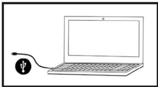
- Connect the product to the PC using a USB cable (not provided) with a suitable connector type (see this detail in the FEATURES OF THE AMPLIFICATION AND CONTROL SECTION chapter).
- In the top right corner of the USB BURNER MANAGER screen, select "File Opening".
- Select the file containing the previously downloaded firmware.
- Follow the operations shown on the screen.
- Click "UPDATE".
VIO-L212
Code 420120270 REV. 1.1
9. SPECIFICATIONS
GENERAL
| Type: Active 3-way line-array module | |
| ACOUSTICAL SPECIFICATIONS | |
| Frequency response [- 10 dB]: 49.8 - 20000 Hz | |
| Frequency response [- 6 dB]: 55 - 18600 Hz | |
| Max SPL: 142 dB (frequency/preset dependent) | |
| HF: 2 x 1.4” (Coil: 3”) | |
| Type of HF transducer: Titanium | |
| MF: 4 x 6.5” (Coil: 2”) | |
| Type of MF transducer: Neodymium | |
| LF: 2 x 12” (Voice Coil: 3”) | |
| Type of LF transducer: Neodymium | |
| Waveguide for high frequencies: Yes | |
| Horizontal directivity: | 90° |
| Vertical directivity: | variable, depending on the configuration and the number of modules |
AMPLIFIER
| Type: | (2x) Digipro® G4 |
| Amplification class: | Class D |
| Amplification power (Peak) | 2x 1600 W (3200 W) |
| Amplification power (RMS): | 2x 3200 W (6400 W) |
| Power supply: | Fullrange with PFC, range 100-240V~ (50-60Hz) |
| Cooling technique: | Convection + fans with lower ventilation grilles |
| Operating temperature range (ambient): | from -15° to + 55° [°C] |
VIO-L212 Code 420120270 REV. 1.1
PROCESSOR
| Internal controller: 32-bit DSP | |
| AD/DA conversion: 24 bit / 96 kHz | |
| DSP advanced functions: Linear-phase FIR filters | |
| Position recognition: inclinometer, NFC technology module | |
| First test internal function: impedance test with sweep |
USER INTERFACE
| Controls: HPF rotary, DSP Preset | |
| Status LEDs Ready, Mute/Prot, Signal, Limiter | |
| RDNet interface LED Link, Active, Remote Preset Active | |
INPUTS AND OUTPUTS
| Power supply inputs and re-links: PowerCON® True In/Link | |
| Audio inputs: 1x XLR IN balanced (insulation: Floating ADC) | |
| Audio outputs: | 1x XLR link OUT balanced |
| RDNet inputs/outputs: | Data In / Data Out (etherCON® connectors) |
| USB (firmware update): | 1x USB MINI type B |
SOFTWARE COMPATIBILITY
| Predictive/testing software | dBTechnologies COMPOSER |
| Remote control software: | AURORA NET |
| Other software: | Ease, Ease Focus 3 |
VIO-L212
Code 420120270 REV. 1.1
POWER SUPPLY SPECIFICATIONS (ABSORPTION)
| Absorption at 1/8th of power in average use conditions (*): | 2 A (230V~) - 3.1 A (115V~) |
| Absorption at 1/3rd of power in maximum use conditions (**): | 4.9 A (230V~) - 7.5 A (115V~) |
| Absorption with speaker on in no-signal condition (idle): | 53 W |
| Inrush current: | 3.2 A |
| Max number of modules per power supply line (**)[mains input + mains link]: | 1 + 2 (220-240V~) / 1 + 1 (100-120V~) |
* NOTE FOR INSTALLER: Values refer to 1/8th of power, under average operating conditions (music programme with occasional or no clipping). For any type of configuration we recommend to consider them as minimum sizing values.
** NOTE FOR INSTALLER: Values refer to 1/3rd of power, under heavy operating conditions (music programme with frequent clipping and limiter activation). In case of professional installations and tours we recommend sizing according to these values.
MECHANICAL SPECIFICATIONS
| Material: wooden cabinet - black polyurea finish | |
| Grille: full metal - CNC machining | |
| Handles integrated (2x side) | |
| Front mounting pre-sets: | Retractable brackets, built-in cabinet points with quick-release pins |
| Rear mounting pre-sets: | Graduated bracket and movable joint with quick-release pins |
| Flown and stacked assembly: With DRK-212 fly-bar accessory | |
| Width: 1100 mm (43.31 inches) | |
| Height: 380 mm (14.96 inches) | |
| Depth: 450 mm (17.72 inches) | |
| Weight: 54.4 kg (119.9 lbs) |
Product features, specifications and appearance are subject to changes without prior notice. dBTechnologies reserve theright to make changes or improvements in design or manufacture without any obligation to incorporate such changes or improvements in previously manufactured products.
A.E.B. Industriale Srl Via Brodolini, 8 Località Crespellano 40053 VALSAMOGGIA BOLOGNA (ITALY)
Tel +39 051 969870
Fax +39 051 969725
www.dbtechnologies.com info@dbtechnologies-aeb.com
INHALTSVERZEICHNIS
1. ALLGEMEINE INFORMATIONEN....57
WILLKOMMEN! 57
6. ZUBEHÖR, INSTALLATION, KONFIGURATION ....70
FLY-BAR DRK-212 70
MODELLADAPTER 70
WAGEN....70
AKUSTISCHE VORHERSAGE / MECHANISCHE VALIDIERUNG....71
natural_image
Technical diagram of a mechanical assembly with labeled components A, B, and W, showing internal cavities and mounting holes (no text or symbols beyond labels)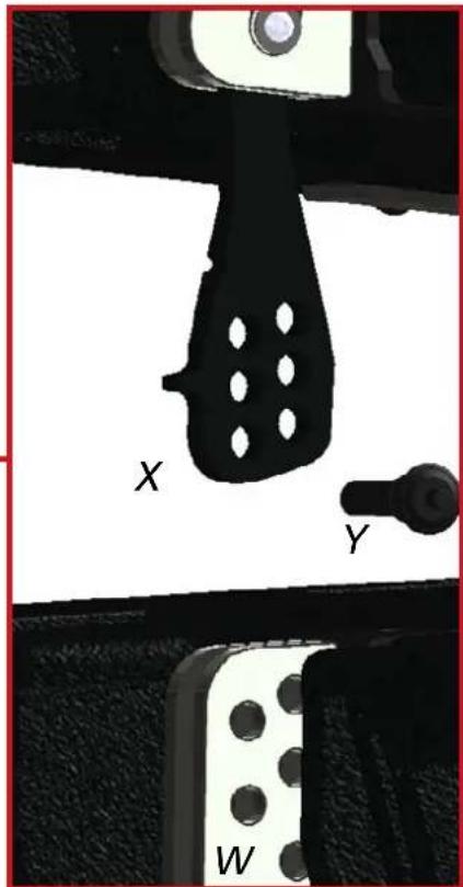
W
FLOWN-INSTALLATION
natural_image
Close-up of black hardware units with attached black cables and control panels, no visible text or symbols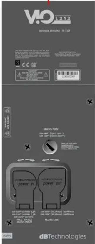
VIO-L212
VIO-L212
![MONITORING PRESET GROUP LOAD/SAVE LOG INCLINOMETER IN ATT 0.0.0 VIO L212 [1] ACOUSTIC INFO ATTENUATION: 0.0 dB HPF: FULL R, Hz COUPLING: A HF COMP: 1 TILT: 0 ° AMPLIFIERS INFO AMP1 AMP2 TEMP: 0 0 °C PSU TEMP: 0 0 °C PSU FREQ: 0 0 Hz MUTE SOLO TEST IDENTIFY LF MF HF OUT -20 -20 -20 -20 -20 -20 -20 -20 -20 -20 -20 -20 -40 -40 -40 -40 -∞ -∞ -∞ -∞ M M M S S S -∞](/content/2026/04/727944/images/133ce2cbf6acc5ab15697433eb8a5b2d6e4a4d3b642da75b0366ab4452de18f6.jpg)
VIO-L212
6. ZUBEHÖR, INSTALLATION, KONFIGURATION
FLY-BAR DRK-212
natural_image
Three black industrial equipment chassis units on wheeled carts, shown from different angles (no visible text or symbols)natural_image
Three black industrial storage units with red wheels, shown from different angles (top, front, and side) against a white background, no visible text or symbols.VIO-L212
VIO-L212
natural_image
Architectural elevation drawing of a multi-level building facade with circular cutouts and structural elements (no text or symbols)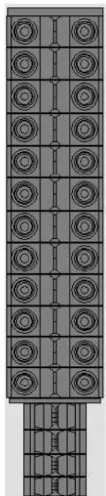
natural_image
Architectural elevation drawing of a multi-level building facade with circular and rectangular panels (no text or symbols)natural_image
Technical line drawing of two stacked rectangular electronic components with mounting brackets (no text or symbols)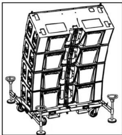
natural_image
Technical line drawing of a multi-tiered industrial storage unit with wheels and mounting feet (no text or symbols)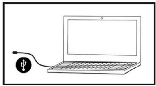
natural_image
Simple line drawing of a laptop connected to a USB cable (no text or symbols)6. ACCESSOIRES, INSTALLATION, CONFIGURATION 96
ADAPTATEURS ENTRE MODÈLES....96
CHARIOTS....96
PRÉDICTION ACOUSTIQUE / VALIDATION MÉCANIQUE ....97
PRÉPARATION DU FLY-BAR ET DES MODULES....97
MONTAGE DU LINE-ARRAY ET CÂBLAGE 98
EXEMPLES DE CONFIGURATIONS MIXTES ....101
EXEMPLES DE CONFIGURATIONS STACKED....102
7. DÉPANNAGE ....103
8. MISE À JOUR DU MICROLOGICIEL....104
9. SPÉCIFICATIONS TECHNIQUES ......105
GÉNÉRAL 105
DONNÉES ACOUSTIQUES....105
AMPLIFICATEUR....105
PROCESSEUR....106
INTERFACE UTILISATEUR 106
ENTRÉES ET SORTIES.... 106
COMPATIBILITÉ LOGICIEL 106
SPÉCIFICATIONS D'ALIMENTATION (ABSORPTION).... 107
SPÉCIFICATIONS MÉCANIQUES....107
VIO-L212
Code 420120270 RÉV. 1.1
1. GÉNÉRALITÉS
BIENVENUE!

INSTALLATION FLOWN
natural_image
Close-up of black hardware units with visible ports and connectors, no readable text or symbols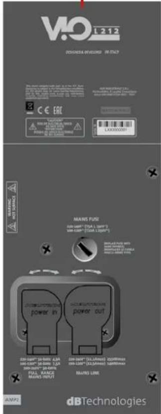
AMP2-ALIMENTATION
AMP1-CONNEXIONS ET CONTRÔLE
![ViD E212 DESIGNED & DEVELOPED IN ITALY System Test USB Data Service Port and Head to test High Pass Filter (Hz) DSP Preset Status Analog Balanced Audio Ready Mate/Prot Signal Unmitator Input Output / Unit RDNet Extension Card Reverse Press Active Active- Link Data In Data Out MAINS 'USE' ENGLISH' [SIA & ISO*] ISO-UNICIP [DATA 1.64W*] dBTechologies AMP1](/content/2026/04/727944/images/f2b3e2326809d73447eaf03d12b2af3225cb219d76ace10eb622175e892f1237.jpg)
VIO-L212
Code 420120270 RÉV. 1.1

flowchart
graph TD
    A["Power Supply"] --> B["Amplifier Module"]
    B --> C["Prepumpifier Module"]
    C --> D["NFC Internal Module"]
    D --> E["Removable Card"]
    E --> F["Output Audio"]
    F --> G["Max Line"]
    G --> H["Auto-Range Max Input"]
    H --> I["Max Line"]
    I --> J["Power Supply"]
    J --> K["Amplifier Module"]
    K --> L["Prepumpifier Module"]
    L --> M["Removable Card"]
    M --> N["Output Audio"]
    N --> O["Max Line"]
    O --> P["Power Supply"]
    P --> Q["Amplifier Module"]
    Q --> R["Prepumpifier Module"]
    R --> S["NFC Internal Module"]
    S --> T["Output Audio"]
    T --> U["Max Line"]
    U --> V["Power Supply"]
    V --> W["Amplifier Module"]
    W --> X["Prepumpifier Module"]
    X --> Y["NFC Internal Module"]
    Y --> Z["Output Audio"]
    Z --> AA["Max Line"]
    AA --> AB["Power Supply"]
    AB --> AC["Amplifier Module"]
    AC --> AD["Prepumpifier Module"]
    AD --> AE["NFC Internal Module"]
    AE --> AF["Output Audio"]
    AF --> AG["Max Line"]
    AG --> AH["Power Supply"]
    AH --> AI["Amplifier Module"]
    AI --> AJ["Prepumpifier Module"]
    AJ --> AK["NFC Internal Module"]
    AK --> AL["Output Audio"]
    AL --> AM["Max Line"]
    AM --> AN["Power Supply"]
    AN --> AO["NFC Internal Module"]
    AO --> AP["Output Audio"]
    AP --> AQ["Max Line"]
    AQ --> AR["Power Supply"]
    AR --> AS["NFC Internal Module"]
    AS --> AT["Output Audio"]
    AT --> AU["Max Line"]
    AU --> AV["Power Supply"]
VIO-L212 Code 420120270 RÉV. 1.1
- ENTRÉE ET RELANCE AUDIO (« Balanced audio »)
VIO-L212
Code 420120270 RÉV. 1.1
| TYPE LED | PHASE D’ALLUMAGE DE L’ENCEINTE | EN FONCTION NORMALE | WARNING GÉNÉRIQUE | BLOCAGE POUR ANOMALIE DE L’ENCEINTE |
| LIMITER ÉTEINT | ÉTEINT, IL S’ALLUME | SEULEMENT EN CAS D’INTERVENTION | CLIGNOTEMENT MOMENTANÉ | CLIGNOTEMENT CYCLIQUE CONTINU |
| SIGNAL | ÉTEINT CLIGNOTEMENT | EN PRÉSENCE DE SIGNAL | SIGNALISATION NORMALE D’AUDIO EN ENTRÉE | ÉTEINT |
| SOURDINE/PROT | ALLUMÉ PENDANT QUELQUES SECONDES | ÉTEINT CLIGNOTEMENT | MOMENTANÉ | ALLUMÉ FIXE |
| PRÊT ÉTEINT | ALLUMÉ FIXE ALLUMÉ FIXE | ÉTEINT |
![MONITORING PRESET GROUP LOAD/SAVE LOG INCLINOMETER IN ATT 0.0.0 VIO L212 [1] +20 0 -10 0 -30 -20 -50 -40 -70 -60 -∞ ACOUSTIC INFO ATTENUATION: 0.0 dB HPF: FULL R. Hz CDUPLING: A HF COMP: 1 TILT: 0 ° AMPLIFIERS INFO AMP1 AMP2 TEMP: 0 0 °C PSU TEMP: 0 0 °C PSU FREQ: 0 0 Hz MUTE SOLO TEST IDENTIFY LF MF HF OUT 0 0 0 0 -20 -20 -20 -20 0 0 0 0 -20 -20 -20 -40 -40 -40 -∞ -∞ -∞ M M M S S S -∞](/content/2026/04/727944/images/e10a05356c23ee771dfd848030bf314502ad353a2fe8db4e52941fb5ce49dc38.jpg)
VIO-L212
Code 420120270 RÉV. 1.1
5. PARAMÈTRES DSP PRESET
6. ACCESSOIRES, INSTALLATION, CONFIGURATION
FLY-BAR DRK-212
natural_image
Three black industrial containerized storage units on wheeled carts, shown from different angles (no text or symbols visible)VIO-L212 Code 420120270 RÉV. 1.1
MONTAGE DU LINE-ARRAY ET CÂBLAGE
VIO-L212
Code 420120270 RÉV. 1.1
EXEMPLES DE CONFIGURATIONS MIXTES
natural_image
Architectural elevation drawing of a multi-level building facade with circular cutouts and structural elements (no text or symbols)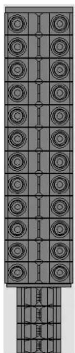
natural_image
Pure architectural or mechanical diagram with circular and rectangular elements, no text or symbols presentVIO-L212 Code 420120270 RÉV. 1.1
EXEMPLES DE CONFIGURATIONS STACKED
natural_image
Technical line drawing of two stacked rectangular electronic components with mounting brackets (no text or symbols)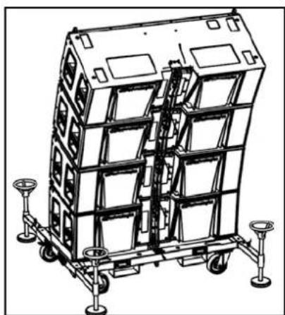
natural_image
Technical line drawing of a multi-tiered industrial container or storage unit with wheels and structural supports (no text or symbols)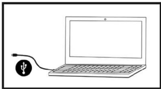
natural_image
Simple line drawing of a laptop connected to a USB cable (no text or symbols)SPÉCIFICATIONS D'ALIMENTATION (ABSORPTION)
natural_image
Technical illustration of a mechanical component with labeled parts X, Y, and W (no text or symbols beyond labels)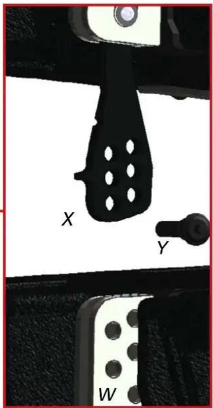
VIO-L212
Cód. 420120270 REV. 1.1
W
INSTALACIÓN FLOWN
natural_image
Close-up of black hardware units with attached black cables and control panels, no visible text or symbols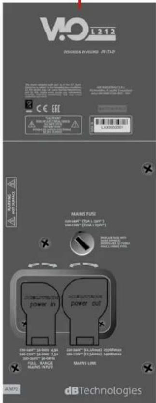
AMP2-ALIMENTAZIONE
AMP1-CONEXIONES Y CONTROL
![VIO E212 DESIGNED & DEVELOPED IN ITALY System Test USB Data Service Port and Head to test High Pass Filter (Hz) DSP Preset Status Ready Mate/Prot Analog Balanced Audio Signal Unimeter Input Output /Line RDNet Extension Card Reverse Press Active Active- List Data in Data Out MAINS 'USE Description' [TBA & LWP] ISO-NAME "DATA & LWP" dBTechnologies AMP1](/content/2026/04/727944/images/23bc3d7649eda1d6cbf9f3d1376bc336863d258f23aa76779ad44521718343ba.jpg)
VIO-L212
Cód. 420120270 REV. 1.1
flowchart
graph TD
    A["Power Supply"] --> B["Amplifier Module"]
    B --> C["Prepumpifier Module"]
    C --> D["NFC Internal Module"]
    D --> E["Removable Card"]
    E --> F["Output Audio"]
    F --> G["Max Line"]
    G --> H["Auto-Range Max Input"]
    H --> I["Max Line"]
    I --> J["Power Supply"]
    J --> K["Amplifier Module"]
    K --> L["Prepumpifier Module"]
    L --> M["Removable Card"]
    M --> N["Output Audio"]
    N --> O["Max Line"]
    O --> P["Power Supply"]
    P --> Q["Amplifier Module"]
    Q --> R["Prepumpifier Module"]
    R --> S["NFC Internal Module"]
    S --> T["Output Audio"]
    T --> U["Max Line"]
    U --> V["Power Supply"]
    V --> W["Amplifier Module"]
    W --> X["Prepumpifier Module"]
    X --> Y["NFC Internal Module"]
    Y --> Z["Output Audio"]
    Z --> AA["Max Line"]
    AA --> AB["Power Supply"]
    AB --> AC["Amplifier Module"]
    AC --> AD["Prepumpifier Module"]
    AD --> AE["NFC Internal Module"]
    AE --> AF["Output Audio"]
    AF --> AG["Max Line"]
    AG --> AH["Power Supply"]
    AH --> AI["Amplifier Module"]
    AI --> AJ["Prepumpifier Module"]
    AJ --> AK["NFC Internal Module"]
    AK --> AL["Output Audio"]
    AL --> AM["Max Line"]
    AM --> AN["Power Supply"]
    AN --> AO["NFC Internal Module"]
    AO --> AP["Output Audio"]
    AP --> AQ["Max Line"]
    AQ --> AR["Power Supply"]
    AR --> AS["NFC Internal Module"]
    AS --> AT["Output Audio"]
    AT --> AU["Max Line"]
    AU --> AV["Power Supply"]
VIO-L212 Cód. 420120270 REV. 1.1
- ENTRADA Y PUENTE AUDIO ("Balanced audio")
natural_image
Three black industrial storage units with red wheels, shown from different angles (top, front, and side) against a plain background.VIO-L212 Cód. 420120270 REV. 1.1
VIO-L212
Cód. 420120270 REV. 1.1

natural_image
Architectural elevation drawing of a multi-level building facade with circular cutouts and structural details (no text or symbols)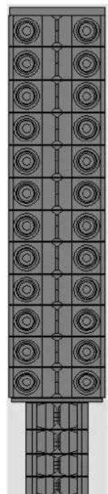
natural_image
Architectural elevation drawing of a multi-level building facade with circular windows and structural beams (no text or symbols)VIO-L212
Cód. 420120270 REV. 1.1
EJEMPLOS DE CONFIGURACIONES STACKED
natural_image
Technical line drawing of two stacked rectangular electronic or mechanical components with mounting brackets (no text or symbols)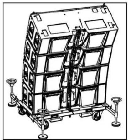
natural_image
Technical line drawing of a multi-tiered industrial container or storage unit with wheels and structural supports (no text or symbols)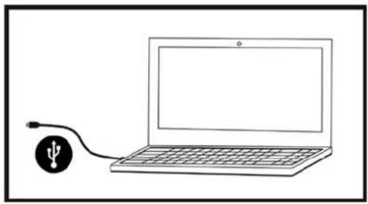
natural_image
Simple line drawing of a laptop connected to a USB cable (no text or symbols)
- FCC APPROVALS (NORTH AMERICA MARKET)
- WARNING
- INDICE
- PARAMETRI DSP PRESET
- MONTAGGIO DEL LINE-ARRAY E CABLAGGIO
- LOCAL CONTROLS AND CONNECTIONS....36
- ACOUSTIC PREDICTION AND MECHANICAL TESTING: DBTECHNOLOGIES COMPOSER40
- AURORA NET 42
- DSP PRESET PARAMETERS ....43
- ACCESSORIES, INSTALLATION, CONFIGURATION ....44
- TROUBLESHOOTING....51
- FIRMWARE UPDATES....52
- SPECIFICATIONS....53
- GENERAL INFORMATION
- WELCOME!
- PRODUCT OVERVIEW
- MECHANICAL AND ACOUSTICAL FEATURES
- FRONT SIDE
- REAR SIDE
- STACKED INSTALLATION
- LOCAL CONTROLS AND CONNECTIONS
- FIR FILTERING
- PFC
- "MAINS INPUT" POWER CONNECTOR
- "MAINS LINK" POWER DAISY CHAIN
- NETWORK FUSE
- ACOUSTIC PREDICTION AND MECHANICAL TESTING: DBTECHNOLOGIES COMPOSER
- AURORA NET
- DSP PRESET PARAMETERS
- ACCESSORIES, INSTALLATION, CONFIGURATION
- MOUNT SOCKETS FOR DIFFERENT MODELS
- DOLLIES
- ACOUSTIC PREDICTION / MECHANICAL TESTING
- PREPARATION OF THE FLY-BAR AND MODULES
- LINE-ARRAY ASSEMBLY AND WIRING
- WARNING!
- INDICATIONS ON POWER SUPPLY AND BEHAVIOUR OF THE LINE-ARRAY SYSTEM
- EXAMPLES OF MIXED CONFIGURATIONS
- EXAMPLES OF STACKED CONFIGURATIONS
- TROUBLESHOOTING
- The module does not turn on:
- The module turns on but produces no sound:
- Module sound is not fully satisfactory.
- FIRMWARE UPDATES
- SPECIFICATIONS
- INHALTSVERZEICHNIS
- ALLGEMEINE INFORMATIONEN....57
- ZUBEHÖR, INSTALLATION, KONFIGURATION ....70
- ZUBEHÖR, INSTALLATION, KONFIGURATION
- ACCESSOIRES, INSTALLATION, CONFIGURATION 96
- DÉPANNAGE ....103
- MISE À JOUR DU MICROLOGICIEL....104
- SPÉCIFICATIONS TECHNIQUES ......105
- GÉNÉRALITÉS
- BIENVENUE!
- INSTALLATION FLOWN
- PARAMÈTRES DSP PRESET
- ACCESSOIRES, INSTALLATION, CONFIGURATION
- MONTAGE DU LINE-ARRAY ET CÂBLAGE
- EXEMPLES DE CONFIGURATIONS MIXTES
- EXEMPLES DE CONFIGURATIONS STACKED
- EJEMPLOS DE CONFIGURACIONES STACKED
Brand : DB Technologies
Model : VIO L212
Category : Loudspeaker