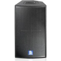
Flexsys F12 - Loudspeaker DB Technologies - Free user manual and instructions
Find the device manual for free Flexsys F12 DB Technologies in PDF.


| Product Type | Active bi-amplified speaker (Full range) |
| Brand | DB Technologies |
| Model | Flexsys F12 |
| Amplifier | Class D, DIGIPRO® |
| RMS Power (low + high) | 300 W + 100 W |
| Frequency Response | 75 Hz – 19 kHz (±3 dB), 65 Hz – 20 kHz (-10 dB) |
| Max Sound Pressure (SPL) | 127 dB |
| Components | 1×12" woofer (2" coil) + 1×1" compression driver (1.5" coil) |
| Dispersion | 90° × 40° (rotatable horn) |
| Crossover Frequency | 1800 Hz, 24 dB/oct |
| Audio Input | Balanced XLR (MIC/LINE, switchable) |
| Input Sensitivity | -3 dBu max |
| Input Impedance | 2.2 kΩ (MIC) / 20 kΩ (LINE) |
| Power Supply | 110-120 V~ / 220-240 V~, 50-60 Hz |
| Cabinet Material | 15 mm Birch Plywood |
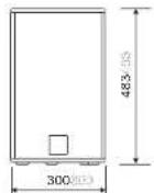
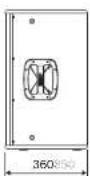
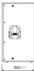
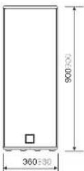
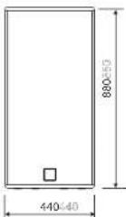
| Dimensions (W × H × D) | 360 × 610 × 360 mm |
| Weight | 16.5 kg |
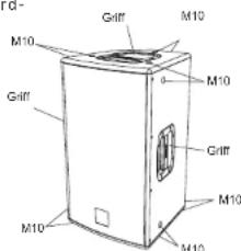
| Fixation Points | 12 × M10 (sides and rear) |
| Pole Mount | 36 mm diameter |
| Handles | 3 (plastic): 2 on sides, 1 on top |
| Color | Black |
| Equalization | Selector "Flat" (linear) / "Processed" (bass boost) |
| Protections | Limiter, thermal control with volume reduction, short circuit |
| Cooling | Passive (no fan) |
| Horn Orientation | Removable and rotatable (90° horizontal or vertical) |
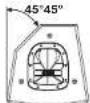
| Monitor Use | 45° floor angle (horn rotation possible) |
Frequently Asked Questions - Flexsys F12 DB Technologies
User questions about Flexsys F12 DB Technologies
0 question about this device. Answer the ones you know or ask your own.
Ask a new question about this device
Download the instructions for your Loudspeaker in PDF format for free! Find your manual Flexsys F12 - DB Technologies and take your electronic device back in hand. On this page are published all the documents necessary for the use of your device. Flexsys F12 by DB Technologies.
USER MANUAL Flexsys F12 DB Technologies
natural_image
Line drawing of a mechanical device with internal components and mounting holes (no text or symbols)F212
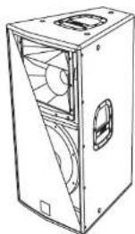
F315
F8
F10
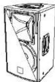
12
MANUALE D'USO
USER MANUAL
BEDIENUNGSANLEITUNG
CARACTERISTIQUES TECHNIQUES



A.E.B. INDUSTRIALE s.r.l.
Via Brodolini, 8 - 40056 Crespellano (Bo) - ITALIA
Tel. + 39 051 969870 - Fax. + 39 051 969725
Internet: www.dblechnologies.com
E-mail: info@dbtechnologies-aeb.com

Made in Italy
COD. 420120139 Rev.2
FLEXSYS F8 - F10 - F12 - F15 FLEXSYS F8 - F10 - F12 - F15
DESCRIZIONE
natural_image
Technical line drawing of a mechanical device with internal components and mounting holes (no text or symbols)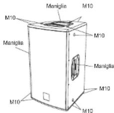
F12-F15
FLEXSYS F8 - F10 - F12 - F15
COMANDI E FUNZIONI
FLEXSYS F212 - F315FLEXSYS F212 - F315
DESCRIZIONE
FLEXSYS F212 (2 vie)
natural_image
Line drawing of a cabinet or enclosure with internal compartments and ventilation slots (no text or symbols)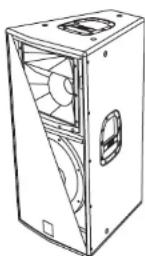
FLEXSYS F212 - F315 FLEXSYS F212 - F315
COMANDI E FUNZIONI
1) CONNETTORE DI INGRESSO "BALANCED INPUT"
4) INDICATORE LUMINOSO "SIGNAL"
FLEXSYS F212 - F315-FLEXSYS F212 - F315
CARATTERISTICHE
Griglie frontali
FLEXSYS F8 FLEXSYS F10 FLEXSYS F12
Componenti 1x6" woofer - 1.5" voice coil 1x10" woofer - 2
TxT compression driver - T voice cal Neodimio TxT compressio Neodimio
Dispersione 90°/40°x60° Asimmetrica 90°/40°x60° Asi
Dimensioni (WxHxD) 260x420x260mm 300x480x300mm
Peso 9,5Kg 12Kg
Maniglie 4. ordinance score 4 in place score
Componenti 1x15" woofer - 2" voice coil 2x12" woofer - 2,5" voice coil 1x15" woofer
1x1 compression driver - 1.5 voice coil 1x1 compression driver - 1.75 voice coil 1x6.5 midrane 1x1"compress
Dispersione 90°x40° 60°x40° 90°x40°
Supporto plantana D36mm D36mm D36mm
The speakers F8, F10, F12 and F15 of FLEXSYS series use cutting edge digital amplifiers of the DIGIPRO ® series, providing with powers 200W and 400W to meet the requirements of any kind of application.
These highly efficient amplifiers provide high power with limited weight and dimension. Thanks to the low power dissipated, the cooling of the amplifier module does not require a fan.
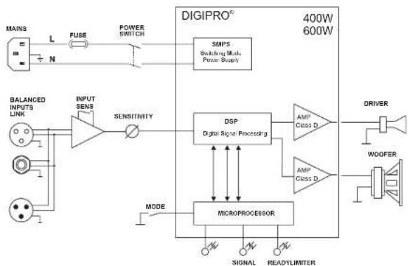
The digital preamplifier with DSP (Digital Signal Processing) controls the audio crossover between the acoustic components, the frequency response, the limiter, and the acoustic alignment. A selector enables to select one of two different equalizations - "FLAT" or "PROCESSED" - to provide high versatility for the different applications.
The amplifiers DIGIPRO 4 400W use power supplies featuring SMPS (Switched-Mode Power Supplies) technology.
This technology increases power supply efficiency and minimizes its weight.
FLEXSYS F8
The F8 bi-amped active speaker is equipped with a DIGIPRO 2 amplifier delivering 150W RMS for the bass section and 50W RMS for the high frequency section.
F8 active two-way speaker features woofer 8" (voice coil 1,5") and a neodymium compression driver 1" (voice coil 1") on a 90°/40°x60° asymmetrical horn.
The speaker is made of 12mm ply wood, the one top handle. How to be threads located on the sides and the back of the speaker are enabling easy transport and installation.
The speaker has been designed to be used also as stage monitor (40° angle), by rotating the horn you can maintain the same audio coverage angle of high frequencies also when the speaker is used as monitor. In the bottom of the box there is a standard pole mount cup (D36mm).
FLEXSYS F10
F10 bi-amped active speaker is equipped with a DIGIPRO 3 amplifier delivering 150W RMS for the bass section and 50W RMS for the high frequency section. F10 active two-way speaker features a woofer 10" (voice coil 2") and a neodymium compression driver 1" (voice coil 1") on a 90°/40°x 60° asymmetrical horn.
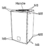
The speaker is made of 12mm plywood, the one top plastic handle and the 12 M8 threads located on the sides and the back of the speaker are enabling easy transport and installation.
The speaker has been designed to be used also as stage monitor (40° angle), by rotating the hom you can maintain the same audio coverage angle of high frequencies also when the speaker is used as monitor. In the bottom of the box there is a standard pole mount cup (D36mm).
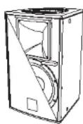
FLEXSYS F8 - F10 - F12 - F15 FLEXSYS F8 - F13
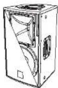
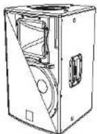
FLEXSYS F12
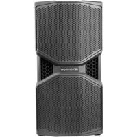
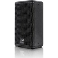
The F12 bi-amped active speaker is equipped with a DIGIPRO® amplifier delivering 300W RMS for the bass section and 100W RMS for the high frequency section.
F12 active two-way speaker features woofer 12" (voice coil 1") and compression driver 1" (voice coil 1.5") on a 90°x40° CD-hom.
The speakers' horizontal directivity is 90° by default factory setting.
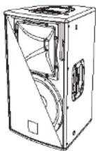
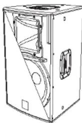
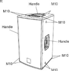
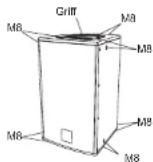
The speaker is made of 15mm birch plywood, the three plastic handles and 12 M10 threads located on the sides and the back of the speaker are enabling easy transport and installation.
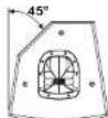
The speaker has been designed to be used also as stage monitor (45° angle), by rotating the horn you can maintain the same audio coverage angle of high frequencies also when the speaker is used as monitor.
In the bottom of the box there is a standard pole mount cup (D36mm).
FLEXSYS F15
F15 bi-amped active speaker is equipped with a DIGIPRO® amplifier delivering 300W RMS for the bass section and 100W RMS for the high frequency section.
F15 active two-way speaker features a woofer 15" (voice coil 2") and a neodymium compression driver 1" (voice coil 1,5") on a 90°x40° CD-hom.
The speakers' horizontal directivity is 90° by default factory setting.
The speaker is made of 15mm birch plywood, the three plastic handles and the 12 M10 threads located on the sides and the back of the speaker are enabling easy transport and installation.
The speaker has been designed to be used also as stage monitor (45° angle), by rotating the horn you can maintain the same audio coverage angle of high frequencies also when the speaker is used as monitor. In the bottom of the box there is a standard pole mount cup (D36mm).
natural_image
Technical line drawing of a mechanical device with internal components and mounting holes (no text or symbols)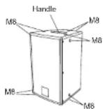
F8
F10
F12-F15
FLEXSYS F8 - F10 - F12 - F15
COMMANDS AND FUNCTIONS
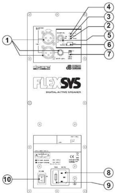
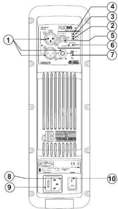
AMPLIFIER PANEL
1) "Balanced Input" - "Link" - "Input Link" CONNECTORS
These balanced inputs can be used to connect balanced or unbalanced microphones or audio sources at line level (0dB) (eg. preamplifier, mixer, recorder, CD player, musical instrument, ...).
The balanced connector is connected in parallel and can be used to send the audio signal to other amplified speakers, recorders or supplementary amplifiers.
2) "Ready" INDICATOR LIGHT
This indicator shows green to indicate that the main power voltage is correct. The LED shows green normal operating conditions.
3) "Signal" INDICATOR LIGHT
This indicator shows green to indicate the presence of the audio signal (at a level of -20dB).
4) "Limiter" INDICATOR LIGHT
This indicator shows red to indicate that the internal limiter circuit has tripped. This prevents amplifier distortion and protects the speakers against overloads.
5) "Sensitivity" INPUT SENSITIVITY CONTROL
This control adjusts the sensitivity of the signal amplifier input. This control does not affect the "Link" - "Input - Link" output level
6) MODE SWITCH
This two-way switch allows to choose between two different system presets. The "Flat" position allows linear response of the speaker, which is mainly suitable for the "live" application. The "Processed" position emphasizes the low frequency and regulates the mid frequency. It is suitable for music play back
7) "Input Sens" SWITCH
Position the switch in LINE to use a line level source (0 dB) or MIC to use a microphone.
8) POWER CABLE SOCKET "MAINS"
Used for connecting the power cable supplied.
9) FUSE CARRIER "FUSE"
Mains fuse housing.
10) POWER SWITCH "POWER"
This switch can be used to switch the diffuser on and off.
REFERENCE DRAWINGS AT PAGES 49 and 50
FLEXSYS F8 - F10 - F12 - F15
CHARACTERISTICS AND PROTECTION
Front Grille
The speakers's components in the box are protected by 1.2mm metal steel grille covered by foam on backside.
Cooling
Thermal control is provided by the internal microprocessor which, by means of two sensors, controls the temperature of the amplifier and of the power supply, avoiding overheating by limiting the overall volume.
In case of overheating (> 80 degrees) the volume decreases proportionally to the temperature increase, making the change unnoticeable.
The correct volume and all the functions are automatically restored when standard operating temperatures are reached.
Switch on
The amplifiers are equipped with a microprocessor to control the DSP and the amplifier.
The correct switch on of the amplifier is ensured by an initialization procedure; during this test stage, the blue front LED flashes twice and the LEDs ("Limiter", "Signal and Ready"), "located on the amplifier module, remain off for approx. 2 sec.
At the end of the switch on procedure, the front LED lights up (if enabled) and on the amplifier module the 'Ready' green LED only remains steadily on.
In case of severe failure of the speaker, the LED on the front panel flashes several times and on the amplifier module, the "Limiter" red LED flashes and the speaker switches to "mute".
Failure indications and safeties
The microprocessor is able to signal three different kinds of failure by flashing the "Limter" red LED on the amplifier panel before the lighting up of the "Ready" green LED. The three types of failure are:
1) WARNING: a non-severe error or auto-ripristinate malfunction is detected and the performance of the speaker is not limited
2) LIMITATION: an error is detected and the performance of the speaker is limited (the sound level is reduced by 3dB). This does not affect the operation of the speaker since it continues to operate. However, it is necessary to call the service centre to solve the issue.
3) FAILURE: a severe malfunction is detected. The speaker switches to "mute".
| Flashing | Indication |
| 1 or 2 | Warning |
| 3 or 4 | Limitation |
| from 5 to 8 | Failure |
In case of failure, the "Ready" green LED remains off.
Perform the checks listed below:
- Check if the speaker is properly connected to the power supply.
- Make sure that the power supply is of correct voltage.
- Check that the amplifier is not overheated.
- Disconnect the speaker from the mains power supply, wait for a few minutes and connect it again.
If after these tests the red "LIMITER" LED is still on, please contact an authorised service centre.
FLEXSYS F212 - F315-FLEXSYS F212 - F315
DESCRIPTION
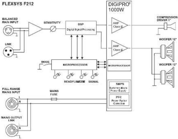
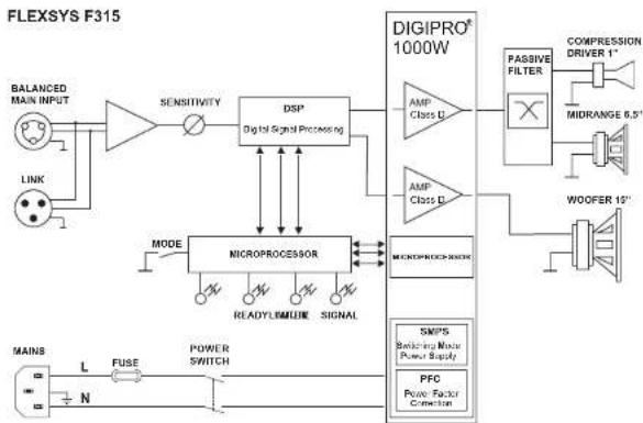
The FLEXSYS series bi-amped speakers are equipped with DIGIPRO ® series class D amplifier. This high-efficiency amplifier delivers high output power in a compact size at low weight. Thanks to its high efficiency the cooling of the amplifier module is obtained statically, thus avoiding the use of a fan.
The power supply circuits of the DIGIPRO 5 amplifier has been conceived to work in full-range mode; thanks to the SMPS (Switched-Mode Power Supply) technology with PFC (Power Factor Correction) the operation with supply voltages between 100 Vac and 240Vac is guaranteed by ensuring the same sound performances even with floating and non-stabilized power supply systems.
FLEXSYS F212 (2 ways)
The F212 bi-amped active speaker is equipped with a DIGIPRO ® amplifier which delivers 500W RMS for the bass section and 250W RMS for the high frequency section.
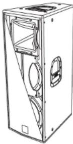
The F212 active two-way speaker features two 12" (voice coil 2.5") woofers and a neodymium 1" (voice coil 1.75") compression driver. The phase plug attached to the front of the upper 12" woofer avoids the vertical phase modulation which usually take place in this type of configuration and ensures a precise horizontal coverage of the medium frequencies.
The speaker is made of 15mm birch ply wood, the 4 handles, the 12 M10 threads located on the sides and the back of the speaker are enabling easy transport and installation.
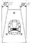
The trapezoidal-shaped housing (20° angle) allows the side-by-side setup of several speakers in cluster configuration. For side-by-side installation, the horn must be turned (40° x 60°)! The bottom features a adjustable foot (in height) to inclinate the tilt angle up to a max. of 5°. This allows to direct the sound radiation without using additional supports.
In the bottom of the box there is a standard pole mount cup (D36mm) made of aluminium
FLEXSYS F315 (3 ways)
The F315 active speaker is equipped with a DIGIPRO® amplifier delivering 500W RMS for the bass section featuring a 15" woofer (voice coil 3") and 500W RMS for the mid-high section featuring a passive filter driving a 6" midrange (voice coil 2") and a 1" compression driver (voice coil 1.5").
The speaker is made of 15mm birch ply wood, the 4 handles, the 12 M10 threads located on the sides and the back of the speaker are enabling easy transport and installation
The 15" woofer and the midh-high section with horizontal 90° coverage is the ideal solution for all demanding full-range applications.
In the bottom of the box there is a standard pole mount cup (D36mm) made of aluminium
natural_image
Line drawing of a rectangular electronic device with internal components and mounting holes (no text or symbols)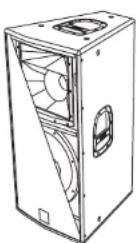
FLEXSYS F212 - F315 FLEXSYS F212 - F315
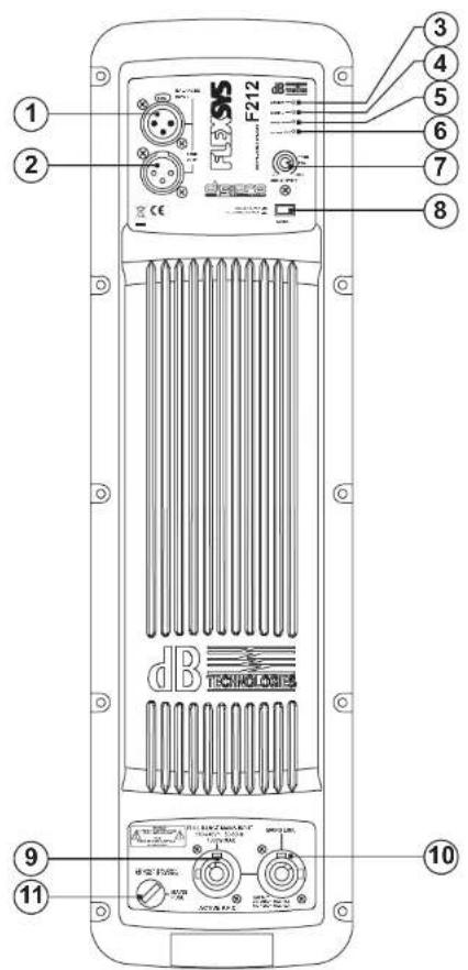
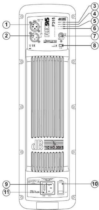
CONTROLS AND FUNCTIONS
1) "BALANCED INPUT" INPUT CONNECTOR
Balanced input at line level. Accepts "XLR" sockets.
2) "BALANCED LINK/OUT" OUTPUT CONNECTOR
The "XLR" connector connected in parallel with input (1) can be used to send the input audio signal to another active speaker.
3) "LIMITER" INDICATOR LIGHT
This indicator shows red to indicate that the internal limiter circuit has tripped. This prevents amplifier distortion and protects the speakers against overloads.
4) "SIGNAL" INDICATOR LIGHT
This indicator showscomes on green to indicate the presence of the audio signal (at a level of -20dB).
5) "MUTE" INDICATOR LIGHT
This yellow indicator indicates amplifier status. The LED is off in normal operating conditions.
6) "READY" INDICATOR LIGHT
This indicator shows green to indicate that the main power voltage is correct. The LED shows green in normal operating conditions
7) "INPUT SENS" INPUT SENSITIVITY CONTROL
This control adjusts the sensitivity of the signal amplifier input. This control does not affect the 'BALANCED LINK/OUT' output level FLEXSYS F212
8) "MODE" SWITCH
This two-way switch allow to choose between two different system presets. The "SINGLE SPEAKER" position allows linear response when one single speaker is used. The "CLUSTERED SPEAKER" position reduces the medium-bass frequencies which are coupling by the side-by-side attachment of several speakers.
9) "MAINS INPUT" POWER SOCKET
For connecting the power cable provided. The connector used for mains connection is a POWER CON® (blue) socket
10) "MAINS OUTPUT LINK" POWER SOCKET
For linking the mains power. The output is connected in parallel with input (9) and can be used to power another active speaker. The connector is a POWER CON® (grey) socket
11) "MAINS FUSE" FUSE CARRIER
Mains fuse housing.
FLEXSYS F315
8) "MODE" SWITCH
This two-way switch allows to choose between two different system presets. The "FLAT" position allows linear response of the speaker, which is mainly suitable for the "live" application in closed rooms. The "PROCESSED" position increases the low frequencies and it is suitable for music play back or for the use in open air applications.
9) POWER CABLE SOCKET "MAINS INPUT"
Used for connecting the power cable supplied.
10) FUSE CARRIER "MAINS FUSE"
Mains fuse housing.
11) POWER SWITCH "POWER"
Switches the active speaker on and off.
REFERENCE DRAWINGS AT PAGES 51 and 52
FLEXSYS F212 - F315FLEXSYS F212 - F315
CHARACTERISTICS
Front Grille
The speakers's components in the buffle are protected by 1.5mm metal steel grille covered by foam on backside.
Cooling
The amplifier is cooled by means of the aluminium panel placed on the back of the speaker.
The thermal protection is ensured by an internal circuit which controls the temperature of the amplifier and protects this against any risk of overheating thus limiting the general volume (temperature >80°C).
If the temperature reaches the maximum operating temperature ( >80ircC ), the audio signal is set to the 'MUTE' position and it will be indicated by the switching on of the yellow "MUTE" LED.
The required volume and all functions will be restored automatically when the normal operating temperatures are reached.
Protection
When the yellow "MUTE" LED turns on, it means that a malfunction has been detected on the speaker, thus setting this to the mute position.
Perform the checks listed below:
- Check if the speaker is properly connected to the power supply.
- Make sure that the power supply is of correct voltage.
- Check that the amplifier is not overheated.
- Disconnect the speaker from the mains power supply, wait for a few minutes and connect it again.
If after these tests the yellow "MUTE" LED is still on, please contact an authorised service centre.
CONNECTIONS (Only for FLEXSYS F212)
Connecting to the mains supply
Each active speaker features its own power cable. Connection is done by a Neutrik POWER CON® (blue) model which permits easy and fast connection to the speaker as well as being an excellent locking system.
The same connector serves as a switch to turn ON and OFF the active loudspeaker by turning the connector to the left (OFF) or right (ON).
The active speaker must be connected to a power supply able to deliver the maximum required power.
Main power supply linking
On the rear of the speaker, a Neutrik POWER CON® connector (grey) offers linking the mains power supply.
This socket links the power supply to another speaker, thereby reducing the direct connections to the mains. Maximum amplifier input power is shown on the amplifier panel.
The maximum number of speakers connected together varies of max input power and of the maximum allowed current of the first power socket.
EMI CLASSIFICATION
According to the standards EN 55103 this equipment is designed and suitable to operate in E3 (or lower E2, E1) Electromagnetic environments.
FLEXSYS F8 - F10 - F12 - F15 - F212 - F315
F1
2-F15
ROTATING HORN (Except FLEXSYS F315)
Loudspeaker allows to maintain the same coverage angle by featuring a rotating horn.
The speakers are always supplied by the manufacturer with the horn positioned horizontal by default at 90° for Flexsys F8, F10, F12 and F15 and 60° by default for F212.
Only Flexsys F212 can be used placing more speakers side by side (cluster), in this case is necessary rotate the horn.
If you wish to change the coverage angle (Fig. 5):
- unscrew the fixing screws of the grille
- remove the front protective grille by slightly pressing on one side and taking the grille off the recessed slots
- unscrew the fixing screws of the horn
- rotate the horn in the desired position (the horn should never be removed from the driver!)
- tighten the fixing screws of the horn
- put the grille back in the recessed slots and tighten the screws of the grille.
LOUDSPEAKER INSTALLATION

WARNING
Make sure that the loudspeaker is securely installed in a stable position to avoid any injuries or damages to persons or property.
For safety reasons do not place one loudspeaker on top of another without proper fastening systems. Before hanging the loudspeaker check all the components for damages, deformations, missing or damaged parts that may compromise safety during installation. If you use the loudspeakers outdoors avoid places that are exposed to bad weather.
The loudspeaker has the following mounting options:
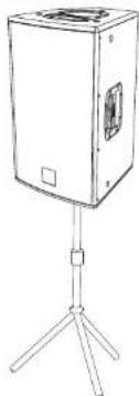
- bookshelf (Fig. 1)
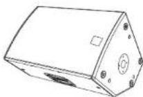
- floor (monitor) (Fig.2)
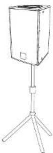
-on speaker stands (Fig.3)
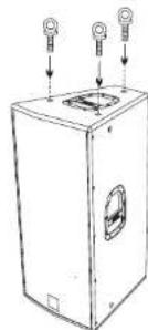
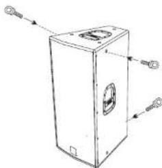
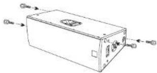
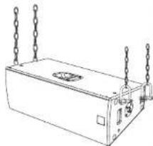
- suspended with support rails or brackets supplied by the manufacturer (Fig.4)

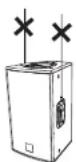
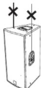
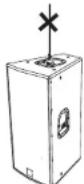
WARNING
Never use the handles to hang the speaker!

WARNING
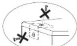
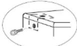
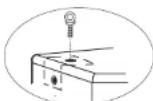
To hang the loudspeaker use only one eyebolt for each hanging point
The hanging points are of M8 threads for Flexsys F8,F10 and M10 threads for Flexsys F12, F15, F212 and F315.
Do not unscrew both bolts recessed in the housing!
WRONG! EXACT!
EXACT!
TECHNICAL SPECIFICATIONS
| FLEXSYS F8 | FLEXSYS F10 | FLEXSYS F12 | |
| System Active Bi-Amp Active Bi-Amp | |||
| Type of amplifier Class D Class D Class D | |||
| RMS power | 150W + 50W | 150W + 50W | 300W + 100W |
| Frequency response | 90-19000Hz (+/-3dB)75-20000Hz (-10dB) 70-20000Hz (-10dB) 65-20000Hz (-10dB) | 80-19000Hz (+/-3dB) | 75-19000Hz (+/-3dB) |
| Crossover | 2050Hz, 24dB/oct 2050Hz, 24dB/oct 1800Hz, 24dB/oct | ||
| Sound pressure (max SPL) | 121dB | 125dB | 127dB |
| Components | 1x8" woofer - 1.5" voice coil1x1" compression driver - 1" voice coilNeodimium | 1x10" woofer - 2" voice coil1x1" compression driver - 1" voice coilNeodimium | 1x12" woofer - 2" voice coil1x1" compression driver - 1.5" voice coil |
| Dispersion | 90"/40"x60" Asymmetrical | 90"/40"x60" Asymmetrical | 90"x40" |
| Input sensitivity | -3dBu Max -3dBu Max -3dBu Max | ||
| Input impedance | 2K2ohm/20Kohm (MIC/LINE) 2K2ohm/20Kohm (MIC/LINE) 2K2ohm/20Kohm(MIC/LINE) | ||
| Power supply | 11C-120Vac 50-60Hz220-240Vac 50-60Hz | 110-120Vac 50-60Hz220-240Vac 50-60Hz | 110-120Vac 50-60Hz220-240Vac 50-60Hz |
| Housing shape | Trapezloidal | Trapezloidal | Trapezloidal |
| Colour | Black | Black | Black |
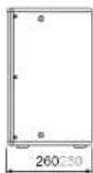
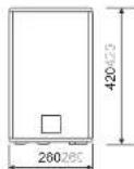
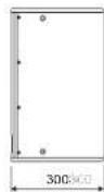
| Dimensions (WxHxD) | 260x420x260mm | 300x480x300mm | 360x610x360mm |
| Weight | 9.5Kg | 12Kg | 16.5Kg |
| Flying support | 10 xM8 | 12 x M8 | 12 x M10 |
| Pole mount cup | D36mm | D36mm | D36mm |
| Handle | --- | --- | 2 (one per side) |
| 1 top side.niche | 1 top side | 1 top side | |
| --- | --- | --- | |
| Rotating horn | Yes | Yes | Yes |
| Integrated tilt unit | No | No | No |
TECHNICAL SPECIFICATIONS
| FLEXSYS F15 | FLEXSYS F212 | FLEXSYS F315 | |
| System | Active Bi-Amp Active Bi-Amp Active Bi-Amp | ||
| Type of amplifier Class D Class | D Class D | ||
| RMS power | 300W + 100W 500W + 2.50W | 500W + 500W | |
| Frequency response | 60-19000Hz (+/-3dB)55-20000Hz (-10dB) 50-20000Hz (-10dB) | 65-19000Hz (+/-3dB) | 60-19000Hz (-3dB)47-20000Hz (-10dB) |
| Crossover | 1800Hz, 24dB/oct | 1800Hz - 24dB/oct | 750Hz - 24dB/oct2000Hz - 18dB/oct passive |
| Sound pressure (max SPL) | 128dB | 132dB | 131dB |
| Components | 1x15" woofer - 2" voice coil1x1" compression driver - 1.5" voice coil | 2x12" woofer - 2,5" voice coil1x1" compression driver - 1,75" voice coil | 1x15" woofer - 3" voice coil1x6,5" midrange - 2" voice coil1x1" compression driver - 1,5" voice coil |
| Dispersion | 90"x40° | 60"x40° | 90"x40° |
| Input sensitivity | -3dBu Max | -3dBu Max -3dBu Max | |
| Input impedance | 2K2ohm/20Kohm (MIC/LINE) | Balanced 20KohmUnbalanced 10Kohm | Balanced 20KohmUnbalanced 10Kohm |
| Power supply | 110-120Vac 50-60Hz220-240Vac 50-60Hz | Full-range with PFC100-240Vac 50-60Hz | Full-range with PFC100-240Vac 50-60Hz |
| Housing shape | Trapezioidal | Trapezioidal | Trapezioidal |
| Colour | Black | Black | Black |
| Dimensions (WxHxD) | 430x680x430mm | 300x480x300mm | 440x880x500mm |
| Weight | 20Kg | 31.5Kg | 31 Kg |
| Flying support | 12 x M10 | 12 x M10 | 12 x M10 |
| Pole mount cup | D36mm | D36mm | D36mm |
| Handle | 2 (one per side)1 top side---- | 2 (one per side)1 top side1 back side,niche | 2 (one per side)1 top side1 back side,niche |
| Rotating horn | Yes | Yes | No |
| Integrated tilt unit | No | Yes | No |
FLEXSYS F8 - F10 - F12 - F15 FLEXSYS F8 - F10 - F12 - F15
BESCHREIBUNG
natural_image
Technical line drawing of a mechanical device with internal components and mounting holes (no text or symbols)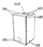
F8
F10
F12-F15
FLEXSYS F8 - F10 - F12 - F15 FLEXSYS F8 - F10 - F12 - F15
BEDIENELEMENTE UND FUNKTIONEN
BEDIENELEMENTE DES VERSTÄRKERS
1) EINGANGSBUCHSEN "BALANCED INPUT" - "LINK" - "INPUT LINK"
FLEXSYS F212 (2 Wege)
natural_image
Line drawing of a cabinet or enclosure with internal compartments and ventilation grilles (no text or symbols)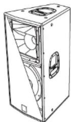
FLEXSYS F212 - F315
BEDIENELEMENTE UND FUNKTIONEN
1) EINGANGSBUCHSE "BALANCED INPUT"
2) AUSGANGSBUCHSE "BALANCED LINK/OUT"
FLEXSYS F212 - F315FLEXSYS F212 - F315
MERKMALE
Frontverkleidung
FLEXSYS F212 (2 voies)
natural_image
Line drawing of a cabinet or enclosure with internal compartments and ventilation grilles (no text or symbols)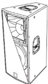
natural_image
Line drawing of a mechanical device with internal fan and mounting holes (no text or symbols)FLEXSYS F212 - F315
COMMANDES ET FONCTIONS
1) CONNECTEUR D'ENTRÉE "BALANCED INPUT"
FLEXSYS F212 - F315 FLEXSYS F212 - F315
CARACTERISTIQUES
Grilles frontales
Contact dB Technologies for accessories to be used with speakers.
Will not accept any responsibility when inappropriate accessories or not suitable additional devices are used.
FLEXSYS F8
FLEXSYS F10
FLEXSYS F12
FLEXSYS F15
FLEXSYS F212 FLEXSYS F212
FLEXSYS F315 FLEXSYS F315
UTILIZZO IN APPOGGIO
SUPPORTED USE
ANWENDUNG
UTILISATION EN APPUI
Fig. 1
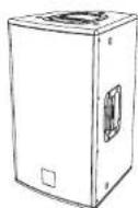
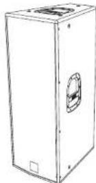
Fig. 2
UTILIZZO A PAVIMENTO (MONITOR)
FLOOR USE (MONITOR)
UTILISATION AU SOL (ECRAN)
SOLO FLEXSYS F8, F10, F12, F15
ONLY FLEXSYS F8, F10, F12, F15
NUR FLEXSYS F8, F10, F12, F15
SEULEMENT FLEXSYS F8, F10, F12, F15
Fig. 3
SUPPORTO PIANTANA STANDARD (D36mm)
STANDARD STAND (D36mm)
STANDARD-HOCHSTANDER (D36mm)
SUPPORT STANDARD (D36mm)
natural_image
Line drawing of a rectangular device mounted on a tripod stand (no text or symbols)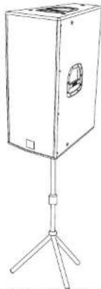
natural_image
Line drawing of a rectangular electronic device mounted on a tripod stand (no text or symbols)APPENDIBILITA' TRAMITE GOLFARI
SUSPENDABLE WITH EYEBOLTS
MAN KANN DEN LAUTSPRECHER MIT RINGSCHRAUBEN HANGEN
POSSIBILITÉ DE SUSPENSION AVEC ANNEAUX
natural_image
Line drawing of a rectangular industrial machine with two circular components and three hanging bulbs (no text or symbols)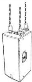
natural_image
Line drawing of a rectangular device with internal components and directional arrows indicating assembly or connection (no text or symbols)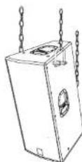
natural_image
Line drawing of a rectangular electronic device with hanging chains and a central vent (no text or symbols)Opzione codice/Optional code/Optionales Zubehör:
TE M8 per/for/für FLEXSYS F8, F10
TE M10 per/for/für FLEXSYS F12, F15, F212, F315
natural_image
Diagram showing a remote control panel with a close-up view of the cable clamping mechanism (no text or symbols present)Adjustable foot (max 5° inclination)
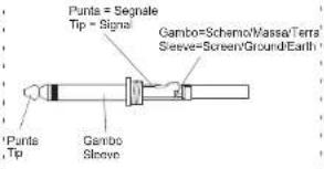
, Unbalanced use of stereo 1/4" jack plug
connettore XLR Unbalanced use with XLR connectors
Pin 6 = Passive/Goldy/Free
Pin 2 = Positive/Hot/+VE Phase


XLR - meschio
Input
YUJ-moi
Pin 1 =Schermo-TerraMassa
Pin 1 = Screen/Ground/Earth
Pin 3 = Connesso al
Pin 3 = Link to Pin 1
Balanced use of stereo 1/4" jack plug
Tip = Positive/Hold+VE Phase
Ring-Negative/Oval-VEHuate
Gambu-Schemio/Massar-Terra Sleeve=Screen/Ground/Earth
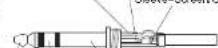
Bunta - Apollo
The Ring
Garrup
Sleeve
Balanced use with XLR connectors
Pin 2 = Positivo/Caldo/Fase + VE
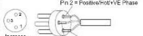
XLR - maschio
Input
XLR - male
Pin 1 = Schemo/Terra/Massa
Fift - Screening Others
Pin 3 = Negative/Fredder/Fase - VE Pin 3 = Negative/Cold VF Phase
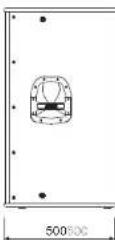
DIMENSIONI
DIMENSIONS
ABMESSUNGEN
DIMENSIONS
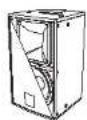
FLEXSYS F10FLEXSYS F8




DIMENSIONI
DIMENSIONS
ABMESSUNGEN
DIMENSIONS
FLEXSYS F15FLEXSYS F12

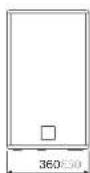

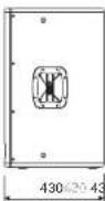
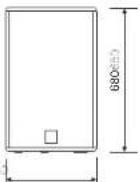
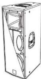
DIMENSIONI
DIMENSIONS
ABMESSUNGEN
DIMENSIONS
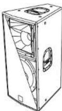
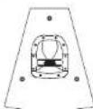
FLEXSYS F315FLEXSYS F2
SCHEMA A BLOCCHI
BLOCK DIAGRAM
BLOCKSCHALTBILD
SCHEMAS FONCTIONNELS
FLEXSYS F8
FLEXSYS F10
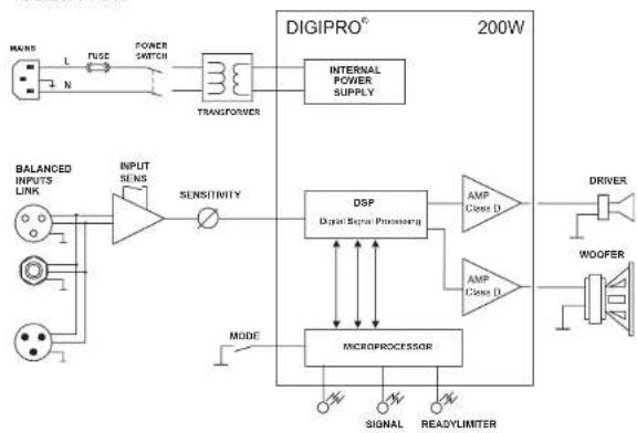
flowchart
graph TD
    A["MAIN"] -->|L N| B["FUSE"]
    B --> C["POWER SWITCH"]
    C --> D["TRANSFORMER"]
    D --> E["INTERNAL POWER SUPPLY"]
    F["BALANCED INPUTS LINK"] --> G["INPUT SENS"]
    G --> H["SENSITIVITY"]
    H --> I["DSP"]
    I --> J["AMP Class D"]
    I --> K["AMP Class D"]
    L["DRIVER"] --> M["WOOFER"]
    M --> N["MICROPROCESSOR"]
    O["MODE"] --> P["SIGNAL"]
    P --> Q["READYLIMITER"]
    R["SIGNAL"] --> S["MODE"]
    T["MODE"] --> U["MODE"]
    V["MODE"] --> W["MODE"]
    X["MODE"] --> Y["MODE"]
    Z["MODE"] --> AA["MODE"]
    AB["200W"] --> AC["DIGIPRO®"]
FLEXSYS F12
FLEXSYS F15
flowchart
graph TD
    A["MAIN"] -->|L| B["FUSE"]
    B --> C["POWER SWITCH"]
    C --> D["SMPS Switching Mode Power Supply"]
    E["BALANCED INPUTS LINK"] --> F["INPUT SENS"]
    F --> G["SENSITIVITY"]
    G --> H["DSP Digital Signal Processing"]
    H --> I["AMP Class D"]
    I --> J["DRIVER"]
    K["MICROPROCESSOR"] --> L["MODE"]
    L --> M["SIGNAL"]
    L --> N["READYLIMITER"]
    O["WOOFER"] --> P["Speaker"]
    Q["400W 600W"] --> R["400W 600W"]
SCHEMA A BLOCCHI
BLOCK DIAGRAM
BLOCKSCHALTBILD
SCHEMAS FONCTIONNELS
flowchart
graph TD
    A["BALANCED MAIN INPUT"] --> B["LINK"]
    B --> C["SENSITIVITY"]
    C --> D["DSP Digital Signal Processing"]
    D --> E["MOOD MICROPROCESSOR"]
    E --> F["READY/LIMONE SIGNAL"]
    F --> G["MAIN SUSE"]
    G --> H["FULL RANGE MAINS INPUT"]
    H --> I["MAINS OUTPUT LINK"]
    I --> J["MAIN SUSE"]
    J --> K["SMPS Switching Mode Power Supply"]
    K --> L["PFC Power Factor Correction"]
    M["COMPRESSION DRIVER 1°"] --> N["AMP Class D"]
    N --> O["AMP Class D"]
    O --> P["MICROPROCESSOR"]
    P --> Q["DIGIPRO® 1000W"]
    Q --> R["AMP Class D"]
    R --> S["AMP Class D"]
    S --> T["WOOFER 12°"]
    T --> U["WOOFER 12°"]
flowchart
graph TD
    A["BALANCED MAIN INPUT"] --> B["Switch"]
    C["LINK"] --> B
    B --> D["Sensitivity"]
    D --> E["DSP® Digital Signal Processing"]
    E --> F["NICROPROCESSOR"]
    F --> G["MODE"]
    G --> H["READY/LIMURE SIGNAL"]
    H --> I["POWER SWITCH"]
    I --> J["FUSE"]
    J --> K["MAIN"]
    L["MAINS"] --> M["L"]
    M --> N["N"]
    N --> O["Output"]
    P["DIGIPRO® 1000W"] --> Q["AMP Class L"]
    P --> R["AMP Class L"]
    P --> S["MICROPROCESSOR"]
    T["PASSIVE FILTER"] --> U["COMPRESSION DRIVER 1*"]
    U --> V["MIDRANGE 6.5°"]
    W["WOOFER 12°"] --> X["Speaker"]
    X --> Y["SMPS Switching Motor Power Supply"]
    Y --> Z["PFC Power Factor Connection"]
- DESCRIZIONE
- FLEXSYS F8 - F10 - F12 - F15
- COMANDI E FUNZIONI
- FLEXSYS F212 - F315FLEXSYS F212 - F315
- FLEXSYS F212 (2 vie)
- FLEXSYS F212 - F315 FLEXSYS F212 - F315
- FLEXSYS F212 - F315-FLEXSYS F212 - F315
- CARATTERISTICHE
- Griglie frontali
- FLEXSYS F8
- FLEXSYS F10
- FLEXSYS F12
- FLEXSYS F15
- COMMANDS AND FUNCTIONS
- AMPLIFIER PANEL
- REFERENCE DRAWINGS AT PAGES 49 and 50
- CHARACTERISTICS AND PROTECTION
- DESCRIPTION
- FLEXSYS F212 (2 ways)
- FLEXSYS F315 (3 ways)
- CONTROLS AND FUNCTIONS
- CHARACTERISTICS
- Front Grille
- Cooling
- CONNECTIONS (Only for FLEXSYS F212)
- Connecting to the mains supply
- Main power supply linking
- EMI CLASSIFICATION
- ROTATING HORN (Except FLEXSYS F315)
- LOUDSPEAKER INSTALLATION
- WARNING
- BESCHREIBUNG
- BEDIENELEMENTE UND FUNKTIONEN
- BEDIENELEMENTE DES VERSTÄRKERS
- FLEXSYS F212 (2 Wege)
- FLEXSYS F212 - F315
- MERKMALE
- Frontverkleidung
- FLEXSYS F212 (2 voies)
- COMMANDES ET FONCTIONS
- CARACTERISTIQUES
Brand : DB Technologies
Model : Flexsys F12
Category : Loudspeaker