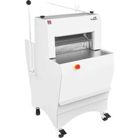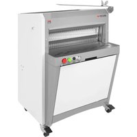
Eco+ 600P - Slicer JAC - Free user manual and instructions
Find the device manual for free Eco+ 600P JAC in PDF.


User questions about Eco+ 600P JAC
0 question about this device. Answer the ones you know or ask your own.
Ask a new question about this device
Download the instructions for your Slicer in PDF format for free! Find your manual Eco+ 600P - JAC and take your electronic device back in hand. On this page are published all the documents necessary for the use of your device. Eco+ 600P by JAC.
USER MANUAL Eco+ 600P JAC
natural_image
Line drawing of a white industrial machine with wheels and ventilation slots (no text or symbols)EN- Translation of original user instructions
Automatic frame slicer Eco+ Face+ 5
1 BEFORE COMMISSIONING 6
2 WARRANTY 6
3 WARNINGS 7
4 TECHNICAL SPECIFICATIONS 8
4.1 Technical specifications ....8
4.2 Details of materials in direct contact with the bread....9
5 INSTALLATION AND COMMISSIONING 9
5.1 Unpacking the machine: 9
5.2 Positioning: 9
5.3 Electrical connection: 10
5.4 Commissioning: 10
5.5 Danger: 10
6 CONTROLS AND SAFETY FEATURES....11
6.1 Controls: 11
6.2 Work areas: 44
6.2 Work area: 11
6.3 Safety features: 11
7 OPERATION....11
8 MAINTENANCE....12
8.1 Daily, by a trained operator....12
8.2 Every 25,000 loaves and/or at least once a year, by an approved agent. 12
8.3 Blade replacement....13
9 CONSUMABLES 14
9.1 List of CONSUMABLES....14
10 MALFUNCTIONS....15
11 ERROR CODES....16
12 LIST OF COMPONENTS IN ILLUSTRATIONS....17

English
1 BEFORE COMMISSIONING
Thank you for choosing a JAC system. It is essential that you read these instructions before installing and commissioning this machine. This will protect you and avoid damaging your machine.
These instructions refer to various illustrations in order to make them easier to understand. These illustrations are at the end of the instructions. Please refer to them whenever you see the following symbols: (fig.X,n°Y).
To ensure that your machine gives you full satisfaction over the coming years, we invite you to familiarise yourself with the following advice:
- Enlist the help of your approved agent for installation, commissioning and service support.
- In order to be covered by the 5-year warranty (see terms and conditions set out below), please have your dealer fill in the service booklet when your machine is being installed. The service booklet is at the back of your machine.
2 WARRANTY

All JAC products are covered by a 5-year warranty.
This warranty is valid for all parts on your machine, including electronic components but excluding consumables. The warranty takes effect on the date the equipment is installed.
Subject to the following restrictive conditions:
- Equipment acquired from an approved dealer;
- Installation carried out by an approved agent;
- Equipment used in accordance with the instructions for use and for the intended purpose for which it was manufactured;
- Equipment serviced on a daily basis in compliance with the instructions for use;
- Regular servicing by the approved agent in compliance with service specifications, with at least one service a year (servicing chargeable to the user).
- Exclusive use of genuine JAC parts.

If there is no record of servicing by an approved agent and/or if the service booklet has not been filled in correctly, warranty cover will be limited to one year.
This warranty does not cover:
- Replacement of consumables (§9);
- Parts not accepted as defective by our company;
- Problems due to improper use of the equipment;
- Problems due to installation not carried out by an approved agent;
- Parts or problems due to transit damage or improper handling.
Repairing and/or replacing defective parts during the warranty period does not bring about an extension of said warranty.

English
3 WARNINGS
It is most important that these user instructions be kept with the machine for any future reference. Should this machine be sold or transferred to another user, please ensure that the user instructions are handed over so that the new user can be familiarised with its operation and the warnings associated with it.

These warnings are given for your safety and that of others. We would therefore ask you to read them carefully before installing and using the machine.
This machine has been designed for use by authorised adults. Please therefore ensure that children do not touch it or use it as a toy.
This machine is intended exclusively for professional use.
It is dangerous to modify or attempt to modify the specifications of this machine.
After having installed this machine, please ensure that it is not standing on the power cable.
Follow the instructions given for its use.
This machine must be stored and used in an indoor room, protected from moisture and heat.
This machine must be adequately illuminated to operate it.
The noise level of this machine does not exceed 75 dB(A) in accordance with EN ISO 3744.
This machine must be used by one person at a time (unless otherwise specified).
This machine is intended for slicing baked bread which has cooled down.

This machine is not intended for the following breads and the following materials:
- Warm bread, stale bread.
- Frozen or partially thawed bread.
- Wholemeal breads with a hard crust and other types of bread with a hard crust.
- Rye breads.
- Non-edible products such as wood, plastic and similar materials.
- Any food that is not included in the bread and loaf cake category.
The machine may be damaged when cutting bread or materials for which the machine is not intended.

Always disconnect the mains supply before cleaning the machine inside/outside and when carrying out maintenance.
This machine is heavy. Take all necessary safety precautions when handling it.

English
4 TECHNICAL SPECIFICATIONS
4.1 Technical specifications
| ECO+ 450 | ECO+ 450 M | ECO+ 600 | ECO+ 450 blower | ECO+ 450 M blower | ECO+ 600 blower | |
| Height (mm) | 1337 | 1337 | 1337 | 1337 | ||
| Width (mm) | 604 | 784 | 1051 | 1231 | ||
| Depth (mm) | 745 | 745 | 829 | 829 | ||
| Entry channel length (mm) | 310 | 300 | 310 | 310 | 300 | 310 |
| Entry channel width (mm) | 440 | 600 | 440 | 600 | ||
| Entry channel height (mm) | 160 | 160 | 160 | 160 | ||
| Packaging (mm) | 800 x 860 x 1600 | |||||
| Net weight (kg) | 165 | 180 | 175 | 190 | ||
| Net weight + packing (kg) | 185 | 200 | 185 | 210 | ||
| Motor power rating (kW) | 0.49 | 1.1 | 1.1 | 0.49 | 1.1 | 1.1 |
| Motor type | Single-phase or three-phase | Three-phase | Single-phase or three-phase | Single-phase or three-phase | Three-phase | Single-phase or three-phase |
| 220 V - 50 Hz (A) | 5 | - | 5 | 5 | - | 5 |
| 380 V - 50 Hz (A) | 3.2 | 3.2 | 3.2 | 3.2 | 3.2 | 3.2 |
| Capacity (loaves/hour) | 200<500 | |||||
| Noiso level (dB) | <75 | |||||
| FACE+ | FACE+ M | |
| Height (mm) | 1418 | 1418 |
| Width (mm) | 604 | 604 |
| Depth (mm) | 654 | 654 |
| Entry channel length (mm) | 310 | 310 |
| Entry channel width (mm) | 440 | 440 |
| Entry channel height (mm) | 160 | 160 |
| Packaging (mm) | 800 × 860 × 1600 | 800 × 860 × 1600 |
| Net weight (kg) | 165 | 165 |
| Net weight + packing (kg) | 185 | 185 |
| Motor power rating (kW) | 0.49 | 0.49 |
| Motor type | Single-phase or three-phase | Three-phase |
| 220 V - 50 Hz (A) | 5 | - |
| 380 V - 50 Hz (A) | 3.2 | 3.2 |
| Capacity (loaves/hour) | 200<500 | 200<500 |
| Noise level (dB) | <75 | <75 |

English
| Heavy duty motor | optional |
| Blower-bagger (ECO+450 - ECO+600) | optional |
| Safety light curtain | optional |
| 4 cm added height | optional |
| Pressure selector | optional |
| Double slice thickness (ECO+600) | optional |
| Daily Incremental counter | optional |
| Special colour | optional |
| Special blades | optional |
4.2 Details of materials in direct contact with the bread.
Infeed table: STAINLESS STEEL 430
Loaf pusher: STAINLESS STEEL 430
Loaf holder: STAINLESS STEEL 430
Blades: Steel
Outfeed table: STAINLESS STEEL 430
Bagger: STAINLESS STEEL 430
5 INSTALLATION AND COMMISSIONING
5.1 Unpacking the machine:
Machines are delivered from our works on pallets, strapped and protected with cardboard. First of all, the packaging must be examined and any damage caused in transit must be declared directly to the carrier.
A. Remove the cardboard and the packaging bag from the machine.
B. Remove straps, taking particular care when they are released by cutting.
C. Detach the machine from its pallet by removing the wooden battens wedging the castors.
D. Take the machine off the pallet. Make sure you do this with at least two people in order to lower it as gently as possible onto the floor.
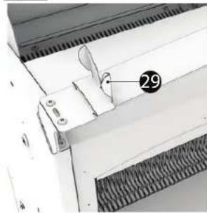
E. Please fit the adjustable bagger stop to the bagger (fig.15, n°29).
After unpacking your machine, check that it has not been damaged in transit. Notify us of any defects.
5.2 Positioning:
In order to achieve excellent performance and long-term reliability, choose a location that is:
Well ventilated, shielded from direct sunlight and away from sources of heat, with a sturdy surface free from vibration.

English
5.3 Electrical connection:
IMPORTANT: This machine must be earthed.
It is recommended that the system be protected with a fuse and an RCD.
Your mains electricity supply to the machine must be protected as indicated below:
- North America: 15 A protection;
- Rest of the world: 16 A protection.
For machines equipped with a variable speed drive, it is imperative that they be connected to a junction box on a circuit fitted with a 300 mA RCD.
Note: Any problem resulting from any other type of connection will not be covered under warranty.
Before connecting your machine to the mains supply and in order to prevent the motor from burning out when it is switched on, it is important to check that the mains supply matches the machine specification (see machine nameplate).
This machine complies with Machinery Directives 2006/42, 2006/95, 2004/108 and is CE marked as proof of this.
Please familiarise yourself with the safety pictograms displayed on the machine:

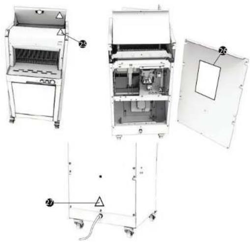
This pictogram indicates a cut hazard. You will find it at the front of the machine around the loaf positioning area (fig.13, n°25).
You will find the circuit diagram for the machine on the back of the electrical enclosure door (fig.13, n°26).

This pictogram indicates an electrocution hazard. Please isolate the machine before carrying out any work on it. You will find it at the back of the machine close to the power cable and inside the machine on the electrical enclosure (fig.13, n°27).
5.4 Commissioning:
Before commissioning, ensure that there are no extraneous objects interfering with the machine's moving parts.
For machine operation, please refer to the "Operation" chapter.
5.5 Danger:
If the user or the machine is in danger, you must use the main isolator switch to cut the power supply to the machine.
Remove the plug from the power socket before any maintenance and/or servicing work. Do not touch the blade, even if it is stationary.
To replace the blade, have the work done by your approved dealer.
Always wear cut-resistant gloves when replacing blades or when working in the vicinity of the blade.

English
Any maintenance work or replacement of parts must be carried out by a qualified individual.
6 CONTROLS AND SAFETY FEATURES
6.1 Controls:
Your slicer is fitted with two buttons as standard:
A start button and an emergency stop button.
It may be fitted with the following additional buttons as an option:
- Pressure selector
- Auto mode.
- Blower start (on machines equipped with a blower).
6.2 Work area:
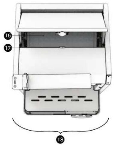
The work area is at the front of the machine (fig.3, n°18).
6.3 Safety features:
This machine is equipped with:
A mechanical safety switch (fig. 10, n°23) (EPK - EPF - EPKS - EPFS - EGK - EGF)
Located at the back of the top cover
Which stops the machine when the top cover is opened (fig.1, n°2).
A mechanical safety switch (fig. 11, n°24)
Located at the bottom of the machine, under the crumb tray
Which prevents the machine form starting when the front door is opened (fig.1, n°8).
Photoelectric cells that prevent the machine from operating when the beam is broken (optional)
(EPL - EPM - EPLS - EPMS - EGL - EGM) (fig.8, n°21).
A safety bar that stops the machine from operating when pressed
(optional) (EPB - EPBS - EPN - EPNS).
7 OPERATION
Braked castors must be locked while the machine is in operation (fig.1, n°13).
Switch on the power to the machine at the start of the day using the emergency stop (fig.1, n°10).
Operating procedure
OPTIONAL: Select type of control using the selector button (fig.4):
1: low speed
2: high speed
ISC: automatic management
OPTIONAL: Press the AUTO (fig.4) button for continuous operation.
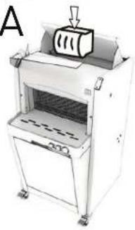
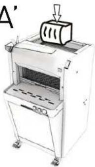
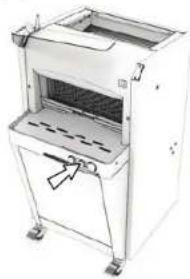
A, A'. Place the loaf on the rear table (fig.3, n°16), between the blades and the moving section (fig.5, fig.6).
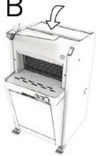
B. Close the lid (fig.1, n°2) (fig.5).
B'. Press the green button (fig.1, n°11) (safety light curtain or safety bar option) (fig.6).
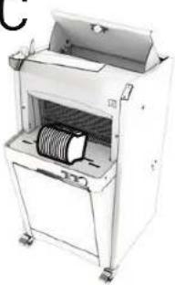
C, C'. Retrieve the loaf from the front table (fig.5) (fig.6).
OPTIONAL: To operate your blower (fig.7, n°19), press the white button located on the right-hand side (fig.7, n°20).
At the end of the day, press the red emergency stop button (fig.1, n°10) to switch the power off to the machine.
Tip: Have a qualified individual check blade tension after the first few days of operation.
Capacity: Number of loaves sliced per day: 6,000 (depending on the type of bread).
Loaf size:
450: (L x W x H) (cm): min.: 12 x 6 x 6 - max.: 44 x 31 x 16
600: (L x W x H) (cm): min.: 12 x 6 x 6 - max.: 58 x 31 x 16
Safety:
Opening the safety cover (fig.1, n°2) prevents the machine from operating.
Passing in front of the photoelectric cells (fig.8, n°21) prevents the machine from operating (machines fitted with this option).
The activation of a safety cut-out is indicated by the green button/indicator light flashing. The number of flashes equates to an error code ( §11 ).
Pressing the safety bar (fig.9, n°22) prevents the machine from operating (EPB – EPBS – EPN – EPNS).
8 MAINTENANCE
8.1 Daily, by a trained operator.
A. Check whether you need to empty the crumb tray.
B. Clean the tables (fig.1, n°5) (fig.3, n°16) using a brush.
C. Use a dry cloth to clean the inside.
D. Use a damp cloth to clean the outside.
8.2 Every 25,000 loaves and/or at least once a year, by an approved agent.
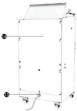
A. Remove the plug from the socket (fig.2, n°15).
B. Check the condition of the cutting blades (fig.1, n°4).
C. If you notice a deterioration in cutting quality, the cutting blades must be replaced (JAC part number; 610001, 610011, 610019 in the JAC Spare Parts catalogue).
D. If the blades need to be replaced, do so in accordance with the blade replacement procedure (fig.12).
E. NB: Do not overtighten the blades, as this risks distorting the frames.
F. Sweep and vacuum the inside of the machine.
G. Check bearing condition, then lubricate them.
H. Lubricate the actuator joints.
Check that your approved agent has recorded his work in your service booklet in order to maintain your 5-year warranty cover.
Additional maintenance for models with lubrication
The oil to be used is: 7940019 (as quoted in the JAC "spare parts" catalogue). Or a food-grade liquid vegetable oil with a natural antioxidant.
Every 1,000 loaves or every 15 days, by a trained operator:
Add the dose of food-grade oil (100 to 150 ml) required to impregnate the felt pads on the loaf pusher (operate the carriage advance button to enable access to the oil filler plug).
Every 25,000 loaves and/or at least once a year, by an approved agent: Remove the plug from the socket. Replace the loaf pusher felt pads.
8.3 Blade replacement.
(fig.12) Always wear cut-resistant gloves (EN 388:2003 version B=5) and safety footwear when replacing blades or when working in the vicinity of blades.
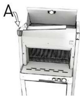
Having ensured that the plug on your machine (fig.2, n°15) has been disconnected from the mains: A. Remove the hanging paddle
A. Remove the bagging paddle. B. Upscrew the front table at the sides of the machine.
B. Onshore the front table C. Remove the front table
C. Remove the front table.
D. Unscrew the cover.
E. Open the cover that protects the blade holder frames. On the upper part of the front frame, remove screws A, which secure the frame to the polypropylene strips (never remove the strips from the frame, as you risk altering factory settings).
F. Lay the frame down forwards. Replace the blades on the rear frame (place something to protect yourself on the front frame blades). Remove the locknuts on screws B (Misch machines). Remove the locknuts on screws B (EPF - EPFS - EPM - EPN). Remove the blade-tightening Allen screws B. Replace the blades, checking that they locate correctly in the swing arm pins. Retighten the blades by tightening screws B, using the blades remaining on the frame as a reference. Then tighten the nuts (machine fitted with lubrication option).
In order not to distort the frame and avoid the risk of dangerous breakages, only replace 1 to 3 blades at a time alternating from left to right.
Resume the procedure from point 6 for the front frame and refit the front frame and the cover sections.
Connect your machine to the mains supply; it is now ready.
Check that your approved agent has recorded his work in your service booklet in order to maintain your 5-year warranty cover.

English
9 CONSUMABLES
When ordering spare parts, check with your approved agent which part is required based on the spare parts catalogue issued by the manufacturer. Always quote the machine serial number shown on the nameplate. Your agent will place the orders with JAC.
9.1 List of CONSUMABLES
| ITEM CODE | DESCRIPTION MODEL | |
| 7240032 | BELT | ALL |
| 5690012 | SLIDE PAD, 140 MM | ALL |
| 5690020 | FRAME STRIP | ALL |
| 5110001 | JAC KNIFE, 13 MM/0.5 MM | ECO+ 450, ECO+ 450 BLOWER, FACE+ 450 |
| 6110011 | JAC KNIFE, 13 MM/0.5 MM + TEFLON | ECO+ 450M, ECO+ 450M BLOWER, FACE+ 450M |
| 5110019 | JAC KNIFE, 13 MM/0.7 MM | ECO+ 600 ECO+ 600M, ECO+ 600 BLOWER |
| 5310026 | LOAF HOLDER SPRING PLASTIC RING | ECO+ 450, ECO+ 450 BLOWER, ECO+ 600, ECO+ 600 BLOWER, FACE+ 450 |
| 5310030 | LOAF HOLDER SPRING STAINLESS STEEL RING | ECO+ 450M, ECO+ 450M BLOWER, ECO+600M, FACE+ 450M |
| 5315013 | GAS SPRING, 40 N | ALL |
| 5690151 | LOAF HOLDER PAD | ALL |
| 5630012 | RUBBER STOP, ∅ 6 MM | ALL |
| 5690102 | JAC FLAP | ALL |
| 5120002 | LOAF PUSHER FELT PAD | ECO+ 450M, ECO+ 450M BLOWER, FACE+ 450M |
| 4-04846 | LOAF PUSHER FELT PAD | ECO+ 600M |

English
10 MALFUNCTIONS
| Problem | Check |
| The machine is not running | Connect the machine using the cable (fig.2, n°15). |
| Unlock the emergency stop (fig 1, n°10). | |
| Close the cover. | |
| Contact your approved agent if the green indicator light is flashing. | |
| Close the front door. | |
| The machine is running, but the loaves are damaged or cut unevenly | Check whether the blades need replacing (fig.12). |
| Leave the bread to cool down for a few hours. | |
| Feed in a loaf of the specified size. | |
| Feed in a loaf that is sufficiently firm. | |
| If the blades are misaligned, adjust the blades and frames. | |
| The bread vibrates between the blades | If the blades are misaligned, adjust the blades and frames. |
| The bread is cut too slowly | Check whether the blades need replacing (fig.12). |
| Choose another pressure setting on your pressure selector (ISC). | |
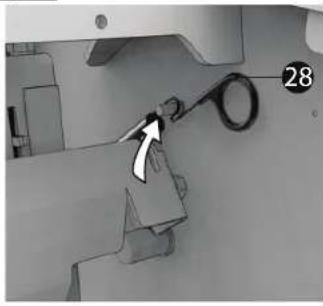
| Check that the loaf holder springs are in place correctly (fig.14, n°28). | |
| The bread tears | If the blades are misaligned, adjust the blades and frames. |
| Check that the loaf holder springs are in place correctly (fig.14, n°28). | |
| Check whether the blades need replacing (fig.12). | |
| Contact your approved agent if the green indicator light is flashing. | |
| The bread emerges very slowly or remains between the blades | Check that the loaf holder springs are in place correctly (fig.14, n°28). |
| The bread is squashed coming out of the blades | Remove a loaf holder spring and repeat your test (fig.14, n°28). |
WARNING: The machine must be isolated from the power supply before attempting any work on it.

Should the problem persist, please contact your technician.

English
11 ERROR CODES
| Flashes or code displayed on screen | Problem description | Action |
| 2 | Cut-out SECU1 tripped during cycle. | Please restart the machine using the emergency stop (fig.1, n°10). Should the problem persist, please contact your technician. |
| 3 | Current to upper actuator (M2) in excess of 6 A for 1 second, during advance/cut. | |
| 4 | Cut motor thermal cut-out (F3) tripped. | |
| 5 | No actuator (M2) movement despite tension set to maximum. | |
| 6 | Loaf pusher not in initial position. Limit switch S1 not tripped. | |
| 7 | Advance/cut cycle time in excess of 60 seconds. | |
| 8 | Return cycle time in excess of 30 seconds. | |
| 9 | Rear (S1) and front (S2) limit switches tripped at the same time. | |
| 10 | Current to upper actuator (M2) in excess of 5 A for 1 second during carriage return. | |
| 11 | Front safety cover (S3) open in the course of a cycle. |

Should the problem persist, please contact your technician.

English
12 LIST OF COMPONENTS IN ILLUSTRATIONS
| Figure | Item | Description |
| 1 | 1 | Top cover magnet |
| 2 | Top cover | |
| 3 | Cover | |
| 4 | Blades | |
| 5 | Front table | |
| 6 | Oil counter reset button | |
| 7 | Crumb tray | |
| 8 | Front door | |
| 9 | Bagger | |
| 10 | Emergency stop button | |
| 11 | Green indicator lamp or illuminated button | |
| 12 | Counter | |
| 13 | Braked castor | |
| 2 | 14 | Rear panel |
| 15 | Power cable | |
| 3 | 16 | Rear table |
| 17 | Magnetic lock | |
| 18 | Work area | |
| 7 | 19 | Bagger-blower |
| 20 | Blower control button | |
| 8 | 21 | Safety cell |
| 9 | 22 | Safety bar |
| 10 | 23 | Mechanical safety switch |
| 11 | 24 | Mechanical safety switch |
| 13 | 25 | “Cut hazard” sign |
| 26 | Circuit diagram | |
| 27 | “Electrocution hazard” sign | |
| 14 | 28 | Detachable loaf holder spring |
| 15 | 29 | Bagger adjustable stop |
text_image
Labeled diagram of a laboratory oven with numbered parts for identificationfig.2
natural_image
Technical line drawing of a rectangular industrial machine with labeled parts (14 and 15), no readable text or symbols beyond labelsfig.3
text_image
Technical diagram of a device with numbered components, likely an electronic or mechanical assembly.fig.5
EPK - EPKS - EPK ETL - EPKS ETL - EPF - EPFS - EGK - EGK ETL - EGF
A
natural_image
Illustration of a laboratory machine with a paper feeding into a chamber (no text or symbols visible)B
natural_image
Illustration of a laboratory machine with a handle and control panel (no text or symbols visible)C
natural_image
Exterior view of a laboratory instrument with a coiled spring inside a chamber (no visible text or symbols)fig.4

text_image
2 1 STOP AUTO STOPfig.6
EPL - EPL ETL - EPM - EPMS - EPLS - EPL ETL - EPB - EPN - EPNS - EGL - EGL ETL - EGM
A
natural_image
Illustration of a laboratory machine with a mounted device and control panel (no visible text or symbols)B'
natural_image
Exterior view of a white industrial machine with open top and side panels (no visible text or symbols)C'

natural_image
Illustration of a laboratory machine with a coiled spring inside, no visible text or symbols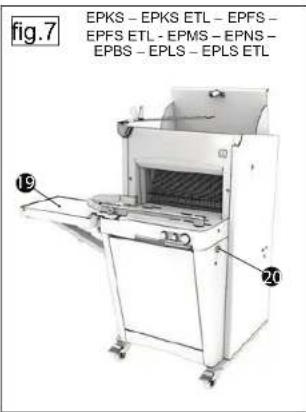
text_image
fig.7 EPKS - EPKS ETL - EPFS - EPFS ETL - EPMS - EPNS - EPBS - EPLS - EPLS ETL 19 20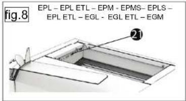
text_image
fig.8 EPL - EPL ETL - EPM - EPMS- EPLS - EPL ETL - EGL - EGL ETL - EGM 21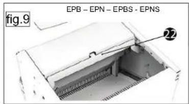
text_image
fig.9 EPB - EPN - EPBS - EPNS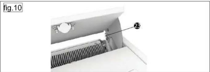
natural_image
Interior view of a mechanical device with a labeled component (no text or symbols visible)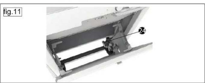
natural_image
Mechanical assembly diagram showing a component with labeled part 24 (no text or symbols beyond label)fig.12
natural_image
Diagram of a laboratory apparatus with labeled component A, showing internal structure without any text or symbols.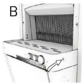
natural_image
Diagram of a device with internal components and an arrow indicating direction (no text or symbols)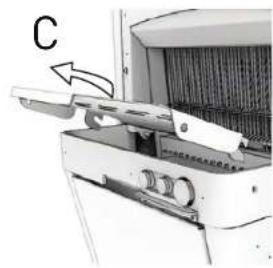
natural_image
Close-up of a mechanical device with a labeled component 'C' and an arrow pointing to a lever mechanism (no readable text or symbols)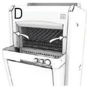
natural_image
Diagram of a portable oven with ventilation grilles and control panel (no text or symbols)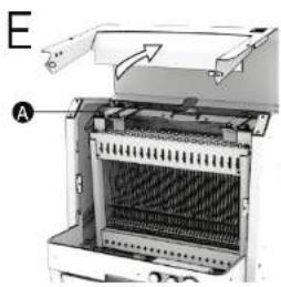
text_image
E A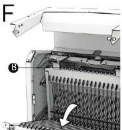
natural_image
Mechanical device with labeled components and directional arrow (no readable text or symbols)fig.13
natural_image
Exploded view diagram of a laboratory apparatus with labeled components (no text or symbols beyond numbers)fig.14
natural_image
Mechanical component diagram showing a lever mechanism with an arrow indicating motion (no text or symbols)fig.15
natural_image
Close-up of a mechanical component with a numbered annotation (29) pointing to a specific part, no readable text or symbols present.
Traditionally Innovative
CONFORMITY DECLARATION TO THE EUROPEAN DIRECTIVES.
DECLARATION DE CONFORMITE AUX DIRECTIVES EUROPEENNES.
The undersigned declares that the machine complies with the European Directives 2006/42/CE, 2014/35/UE, 2014/30/UE.
FR
Technical files compiled by:
Complies with the following (parts of)
European Harmonised Standards:
EN 1672-2
1935/2004
IEC 60204-1
EN ISO 12100-1 EN ISO 17180 355-56
EN 13054 is applicable
EN 61000-3-2, 3-2, 6-1, 6-3
Adrien Craeninckx
Chief Executive Officer
JAC 9.8